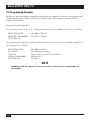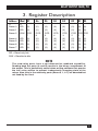
1
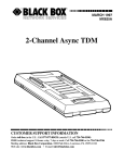
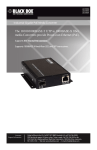
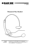
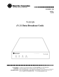
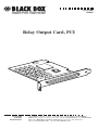
JULY 2000
IC905C
Relay Output Card, PCI
CUSTOMER
SUPPORT
INFORMATION
Order toll-free in the U.S. 24 hours, 7 A.M. Monday to midnight Friday: 877-877-BBOX
FREE technical support, 24 hours a day, 7 days a week: Call 724-746-5500 or fax 724-746-0746
Mail order: Black Box Corporation, 1000 Park Drive, Lawrence, PA 15055-1018
Web site: www.blackbox.com • E-mail: [email protected]
RELAY OUTPUT CARD, PCI
FEDERAL COMMUNICATIONS COMMISSION
AND
INDUSTRY CANADA
RADIO FREQUENCY INTERFERENCE STATEMENTS
This equipment generates, uses, and can radiate radio frequency energy and if not
installed and used properly, that is, in strict accordance with the manufacturer’s
instructions, may cause interference to radio communication. It has been tested
and found to comply with the limits for a Class A computing device in accordance
with the specifications in Subpart J of Part 15 of FCC rules, which are designed to
provide reasonable protection against such interference when the equipment is
operated in a commercial environment. Operation of this equipment in a
residential area is likely to cause interference, in which case the user at his own
expense will be required to take whatever measures may be necessary to correct the
interference.
Changes or modifications not expressly approved by the party responsible for
compliance could void the user’s authority to operate the equipment.
This digital apparatus does not exceed the Class A limits for radio noise emission from digital
apparatus set out in the Radio Interference Regulation of Industry Canada.
Le présent appareil numérique n’émet pas de bruits radioélectriques dépassant les limites
applicables aux appareils numériques de la classe A prescrites dans le Règlement sur le
brouillage radioélectrique publié par Industrie Canada.
1
RELAY OUTPUT CARD, PCI
EMC DIRECTIVE STATEMENT
Products bearing the CE label fulfill the requirements of the EMC Directive
(89/336/EEC) and of the low-voltage directive (73/23/EEC) issued by the
European Commission.
To obey these directives, the following European standards must be met:
• EN55022 Class A—“Limits and methods of measurement of radio interference
characteristics of information technology equipment.
• EN50082-1—“Electromagnetic Compatibility—Generic Immunity Standard”
Part 1: Residential, commercial, and light industry.
• EN60950 (IEC950)—“Safety of information technology equipment, including
electrical business equipment.
2
RELAY OUTPUT CARD, PCI
NORMAS OFICIALES MEXICANAS (NOM)
ELECTRICAL SAFETY STATEMENT
INSTRUCCIONES DE SEGURIDAD
1. Todas las instrucciones de seguridad y operación deberán ser leídas antes de
que el aparato eléctrico sea operado.
2. Las instrucciones de seguridad y operación deberán ser guardadas para
referencia futura.
3. Todas las advertencias en el aparato eléctrico y en sus instrucciones de
operación deben ser respetadas.
4. Todas las instrucciones de operación y uso deben ser seguidas.
5. El aparato eléctrico no deberá ser usado cerca del agua—por ejemplo, cerca
de la tina de baño, lavabo, sótano mojado o cerca de una alberca, etc..
6. El aparato eléctrico debe ser usado únicamente con carritos o pedestales que
sean recomendados por el fabricante.
7. El aparato eléctrico debe ser montado a la pared o al techo sólo como sea
recomendado por el fabricante.
8. Servicio—El usuario no debe intentar dar servicio al equipo eléctrico más allá
a lo descrito en las instrucciones de operación. Todo otro servicio deberá ser
referido a personal de servicio calificado.
9. El aparato eléctrico debe ser situado de tal manera que su posición no
interfiera su uso. La colocación del aparato eléctrico sobre una cama, sofá,
alfombra o superficie similar puede bloquea la ventilación, no se debe colocar
en libreros o gabinetes que impidan el flujo de aire por los orificios de
ventilación.
10. El equipo eléctrico deber ser situado fuera del alcance de fuentes de calor
como radiadores, registros de calor, estufas u otros aparatos (incluyendo
amplificadores) que producen calor.
11. El aparato eléctrico deberá ser connectado a una fuente de poder sólo del
tipo descrito en el instructivo de operación, o como se indique en el aparato.
3
RELAY OUTPUT CARD, PCI
12. Precaución debe ser tomada de tal manera que la tierra fisica y la polarización
del equipo no sea eliminada.
13. Los cables de la fuente de poder deben ser guiados de tal manera que no
sean pisados ni pellizcados por objetos colocados sobre o contra ellos,
poniendo particular atención a los contactos y receptáculos donde salen del
aparato.
14. El equipo eléctrico debe ser limpiado únicamente de acuerdo a las
recomendaciones del fabricante.
15. En caso de existir, una antena externa deberá ser localizada lejos de las lineas
de energia.
16. El cable de corriente deberá ser desconectado del cuando el equipo no sea
usado por un largo periodo de tiempo.
17. Cuidado debe ser tomado de tal manera que objectos liquidos no sean
derramados sobre la cubierta u orificios de ventilación.
18. Servicio por personal calificado deberá ser provisto cuando:
A: El cable de poder o el contacto ha sido dañado; u
B: Objectos han caído o líquido ha sido derramado dentro del aparato; o
C: El aparato ha sido expuesto a la lluvia; o
D: El aparato parece no operar normalmente o muestra un cambio en su
desempeño; o
E: El aparato ha sido tirado o su cubierta ha sido dañada.
4
RELAY OUTPUT CARD, PCI
TRADEMARKS USED IN THIS MANUAL
Windows® and Windows NT® are registered trademarks of Microsoft Corporation.
Linux® is a registered trademark of Linus Torvalds.
Any other trademarks mentioned in this manual are acknowledged to be the
property of the trademark owners.
5
RELAY OUTPUT CARD, PCI
Contents
1. Specifications. . . . . . . . . . . . . . . . . . . . . . . . . . . . . . . . . . . . . . . . . . . . . . 7
2. Introduction . . . . . . . . . . . . . . . . . . . . . . . . . . . . . . . . . . . . . . . . . . . . . . 8
2.1 Overview . . . . . . . . . . . . . . . . . . . . . . . . . . . . . . . . . . . . . . . . . . . . . . 8
2.2 What the Package Includes . . . . . . . . . . . . . . . . . . . . . . . . . . . . . . . 8
2.3 Features . . . . . . . . . . . . . . . . . . . . . . . . . . . . . . . . . . . . . . . . . . . . . . . 8
2.4 Reed Relays . . . . . . . . . . . . . . . . . . . . . . . . . . . . . . . . . . . . . . . . . . . . 9
2.5 Software . . . . . . . . . . . . . . . . . . . . . . . . . . . . . . . . . . . . . . . . . . . . . . . 9
2.6 Programming Examples . . . . . . . . . . . . . . . . . . . . . . . . . . . . . . . . . . 10
3. Register Description . . . . . . . . . . . . . . . . . . . . . . . . . . . . . . . . . . . . . . . . 11
4. Installation . . . . . . . . . . . . . . . . . . . . . . . . . . . . . . . . . . . . . . . . . . . . . . . 12
4.1 Software Installation . . . . . . . . . . . . . . . . . . . . . . . . . . . . . . . . . . . . . 12
4.2 Hardware Installation . . . . . . . . . . . . . . . . . . . . . . . . . . . . . . . . . . . . 12
Appendix A. Board Layout . . . . . . . . . . . . . . . . . . . . . . . . . . . . . . . . . . . . 13
Appendix B. Troubleshooting. . . . . . . . . . . . . . . . . . . . . . . . . . . . . . . . . . 14
6
RELAY OUTPUT CARD, PCI
1. Specifications
Compliance—CE approval; FCC Part 15, Class A
Channels—16 relays
Relay Contact Power Ratings—10 watts maximum
Relay Contact Voltage Maximum—100 volts DC or AC maximum
Relay Contact Current Maximum—0.5 amps DC or AC RMS
Relay Contact Resistance, Initial—0.15 ohms
Relay Rated Life—Low Load: 200 million closures; Maximum Load: 100 million
closures
Relay Contact Speed—Operate: 0.5 ms; Release: 0.5 ms; Bounce: 0.5 ms
Maximum Operating Speed—600 Hz
Connectors—(1) DB37 male
MTBF—Greater than 150,000 hours, excluding relays. Relay life expectancy
depends on actual application usage.
Temperature—Operating: 32 to 122°F (0 to 50°C); Storage: -4 to +158°F (-20 to
+70°C)
Humidity—10 to 90%, noncondensing
Power—From the PCI bus
Size—Including goldfingers: 3.9"H x 5"L (9.9 x 12.7 cm);
Excluding goldfingers: 3.6"H x 5"L (9.1 x 12.7 cm)
Weight—3.2 oz. (90.7 g)
7
RELAY OUTPUT CARD, PCI
2. Introduction
2.1 Overview
The Relay Output Card, PCI provides 16 reed relays that can latch power, data, or
other electronic signals for control applications. The Card is PCI 2.1 bus
compliant.
2.2 What the Package Includes
Your package should contain the following items:
• (1) Relay Output Card, PCI
• (3) Systems software diskettes: (1) disk with drivers for DOS and Windows® 95,
(2) disks with drivers for Windows 98, 2000, or Windows NT®
• This users’ manual
If anything is missing or damaged, please call Black Box at 724-746-5500.
2.3 Features
• 16 SPST relays.
• DB37 male connector.
• Highly reliable 10-VA DIP reed relays.
• Multiple adapters can reside in the same computer.
• PCI 2.1 bus compliant.
8
RELAY OUTPUT CARD, PCI
2.4 Reed Relays
Reed relays provide very-high-quality, long-life, low-power, dry-contact switch
closures. Reed relays are not suited for high-current applications, and can be
destroyed by inductive load switching, where a spark occurs across the contacts
internally. The relays are normally open, and close when energized.
Port Bit
Relay-K#
DB37 Male Connector and Pin No.
Port C Bit
0
1
2
3
4
5
6
7
K1
K2
K3
K4
K5
K6
K7
K8
2, 20
3, 21
4, 22
5, 23
6, 24
7, 25
8, 26
9, 27
Port D Bit
0
1
2
3
4
5
6
7
K9
K10
K11
K12
K13
K14
K15
K16
10, 28
11, 29
12, 30
13, 31
14, 32
15, 33
16, 34
17, 35
Ground
+5 volts
+12 volts
18, 36, 37
19
1
2.5 Software
The Relay Output Card, PCI ships with an I/O suite of software drivers. Popular
development environments, including Visual C++, Visual Basic, and Delphi, are
supported for application development. The Card includes a utility for configuring
the driver parameters under Windows, further simplifying installation.
For DOS, QNX, Linux®, and other operating systems, please refer to the
software included with your card.
9
RELAY OUTPUT CARD, PCI
2.6 Programming Examples
Below are several simple examples using 80 x 86 assembly code for energizing and
checking the state of the reed relays on the Card. All examples assume a base
address of 300 hex.
Programming Example #1:
To set relay #3 on, write a “1” in bit-position D2, to port address base+3 or 303 hex.
MOV DX,303H
MOV AL,00001000B
OUT DX, AL
;Set DX to Port D
;Set DX to Port D
Programming Example #2, another method that takes into account the readback capability of
the output ports C and D:
MOV DX,303H
IN AL,DX
NOT AL
OR AL,00001000B
OUT DX,AL
;Set DX to Port D
;Get old port setting
;Invert bits—see the Note below
;OR in bit 3
;Set bit 3
NOTE
Reading back the ports (C and D) results in the binary complement of
the output.
10
RELAY OUTPUT CARD, PCI
3. Register Description
Address
Mod D7
S
Base+0
Base+1
Base+2
E
RD
RD
R/W
Base+4
Base+5
Base+6
Base+7
RD
RD
RD
RD
{0}
{0}
PCD
7
{0}
{0}
{0}
{0}
D6
D5
D4
D3
D2
D1 D0
{0}
{0}
PCD
6
{0}
{0}
{0}
{0}
{0}
{0}
PCD
5
{0}
{0}
{0}
{0}
{0}
{0}
PCD
4
{0}
{0}
{0}
{0}
{0}
{0}
PCD
3
{0}
{0}
{0}
{0}
{0}
{0}
PCD
2
{0}
{0}
{0}
{0}
{0}
{0}
PCD
1
{0}
{0}
{0}
{0}
{0}
{0}
PCD
0
{0}
{0}
{0}
{0}
RD = Read-only bits
R/W = Read/write bits
NOTE
The reed-relay ports have a non-destructive readback capability.
Reading back the ports (A and B) results in the binary complement of
the output. This is particularly useful when writing software that queries
the last value written to prevent inadvertently changing state of the
relays. Also, bits in the read-only ports (Base+0, 1, 4-7) are decoded but
not used by the Card.
11
RELAY OUTPUT CARD, PCI
4. Installation
NOTE
You must install the software before you setup the hardware.
4.1 Software Installation
The Relay Output Card, PCI is a fully compliant PCI plug-and-play adapter. The
I/O address is automatically assigned by either your system or your plug-and-play
operating system.
For Windows users:
Choose “Install Software” at the beginning of the CD and select the digital I/O
software drivers.
4.2 Hardware Installation
1. Turn off the PC’s power. Disconnect the power cord.
2. Remove the PC case cover.
3. Locate an available PCI slot and remove screw and the blank metal slot cover.
4. Gently insert the Card into the slot. Make sure that the Card is seated
properly.
5. Replace the screw.
6. Replace the cover.
7. Connect the power cord.
Installation is complete.
12
RELAY OUTPUT CARD, PCI
Appendix A. Board Layout
13
RELAY OUTPUT CARD, PCI
Appendix B. Troubleshooting
B.1 Calling Black Box
If you determine that your Relay Output Card, PCI is malfunctioning, do not
attempt to alter or repair the unit. It contains no user-serviceable parts. Contact
Black Box at 724-746-5500.
Before you do, make a record of the history of the problem. We will be able to
provide more efficient and accurate assistance if you have a complete description,
including:
• the nature and duration of the problem.
• when the problem occurs.
• the components involved in the problem.
• any particular application that, when used, appears to create the problem or
make it worse.
B.2 Shipping and Packaging
If you need to transport or ship your Relay Output Card, PCI:
• Package it carefully. We recommend that you use the original container.
• If you are shipping the Relay Output Card, PCI for repair, make sure you
include everything that came in the original package. Before you ship, contact
Black Box to get a Return Materials Authorization (RMA) number.
14
© Copyright 2000. Black Box Corporation. All rights reserved.
1000 Park Drive
•
Lawrence, PA 15055-1018
•
724-746-5500
•
Fax 724-746-0746