1
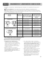
RELEASING THIS DRAWING
WITHOUT PERMISSION LG
Electronics SHOULD BE
ACCUSED ACCORDING TO THE
LAWS AND COMPANY RULES.
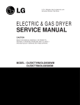
3828EL3003M
이 도면은 LG전자의 자산으로 불법
유출시 관계법과 회사규정에 의해 처벌됨.
WORK
SEC.
가
BRAND
나
MODEL
LG
DLE9577WM / DLG9588WM
DLE9577SM / DLG9588SM
M
다
P/NO.
3828EL3003M
PRINTING DEGREE
MATERIAL AND PRINTING DESCRIPTION
EXTERIER INTERIER
1
1
LG MODEL 명
SNOW WHITE 100g OFFSET 인쇄
LANGUAGE
ENGILSH
SPANISH
-
PAGE
REMARK
68
LGEUS
<< 주기 >>
<BACK>
<FRONT>
P/NO. 다
가
280
나
1.
2.
3.
4.
5.
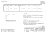
재질, 인쇄방법, 인쇄도수, 외곽치수등은 작업표에 준한다.
인쇄내용, 문자크기 및 형상, 선의 굵기 등은 설계에서 제시된 FILM에 준함.
외곽치수는 절단후 치수임.
양산전에 설계 한도를 득할 것.
본 부품에 금지물질이 포함되지 않도록 하고,
상세 내용은 LG(63)-A-5501-34를 만족할 것.
나
가
<< NOTES >>
215
215
1.
2.
3.
4.
5.
Material, printing and exterier size are refer to work tables.
Printing, text size and line are based on LG design film.
Exterier size on the drawing is cutting line.
Before product controlled by criteria sample.
The part should not contain prohibited substances(Pb,Cd,Hg,Cr+6,PBB,PBDE)
and details should comply with LG standard of LG(63)-A-5501-34.
PDF
ILLUSTRATOR
TRIG.
1
서비스센타 Call No 추가.
AWCL604388
06.07.12
김진영
윤주한
2
3
4
REV. NO.
기호
REVISION DESCRIPTION
변경 사항
REF. NO.
시방 번호
DATE
년/월/일
PREPARED APPROVED
시방자
승인자
mm
SCALE
1
MODELING DESIGNED REVIEWED CHECKED APPROVED
김진영
06.07.05
LG 전자
5
UNIT
1
(주)
LG Electronics Inc.
허선일
06.07.06
윤주한
06.07.06
RELATED DWG.
T
I
T
L
E
DWG.
No.
DR COMPLETED
도면 DR 완료
완료일 :
MANUAL,OWNER’S
GIANT(D)-PJT
1/1
3828EL3003M
☎ 1-800-243-0000
para el Servicio LG (Atención al Cliente) 24 horas al día, 7 días a la semana
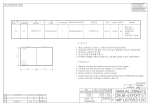
DLE9577WM / DLG9588WM
DLE9577SM / DLG9588SM
Gracias por comprar una Secadora LG. Por favor lea su
manual correctamente, ya que
contiene informaciòn importante de una instalaciòn segura,
Uso y mantenimiento. Guarde el modelo y nùmero de serie y
conserve su manual para futuras referencias.
Para más información, visite nuestro sitio web http//us.lge.com
☎ 1-800-243-0000
24 HOURS A DAY, 7 DAYS A WEEK FOR LG CUSTOMER SERVICE
DLE9577WM / DLG9588WM
DLE9577SM / DLG9588SM
Thank you for buying an LG Dryer.
Please read your manual carefully, as it provides instructions
on safe Installation, use and maintenance.
Record the model and serial numbers,
and retain the manual for future reference.
For more information, visit our website at http://us.lge.com
P/No.: 3828EL3003M
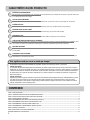
PRODUCT FEATURES
1
2
3
4
5
6
7
8
OUTSTANDING PERFORMANCE
Besides the large capacity, you can benefit from faster drying time, quiet operation, and energy efficiency.
STAINLESS STEEL DRUM
Stainless steel drum doesn’t rust.
ARTISTIC DESIGN
Modern front panel look and big crystal-clear glass door make your dryer stylish.
DIGITAL FABRIC CARE
Multi-Level temperature control takes better care of your clothes.
EASE OF USE
An entire selection of user-friendly functions make operating the dryer easy.
USING THE RLM (REMOTE LAUNDRY MONITOR)
The RLM monitors status of your dryer. You can plug the display unit into any power outlet in your home.
The RLM Display Unit can be purchased separately for this dryer.
ADAPTABLE CONTROL
The control panel can be in the top or bottom position to allow easy access whether side-by-side or stacked
on a washer.
ONE TOUCH SELECTIONS
To choose an option, press its button once. No need to press buttons multiple times to scroll through a list of
options.
What are Sensor Dry and Time Dry?
Your dryer provides sensor drying and time drying programs.
Sensor Dry
The dryer senses the dampness of the laundry and automatically determines the heat level and operation time. You might
see a sudden increase or decrease in operation time if the sensor determines more or less drying is required. This is not a
malfunction.
Time Dry
Use TIME DRY to select heat level and drying time manually. This can be used if clothes are not as dry as you like them
at the end of the cycle. Use TIME DRY for heavy and bulky items and thick work.
TABLE OF CONTENTS
PART 1. SPECIFICATIONS .................................................................................................................................................................................................................3
PART 2. IMPORTANT WARRANTY AND SAFETY INSTRUCTIONS ................................................................................................................................................4
PART 3. INITIAL STEPS FOR INSTALLING YOUR DRYER ..............................................................................................................................................................7
PART 4. ACCESSORIES INSTALLATION ........................................................................................................................................................................................15
PART 5. ELECTRICAL REQUIREMENTS FOR ELECTRIC DRYER.................................................................................................................................................17
PART 6. ELECTRICAL REQUIREMENTS FOR GAS DRYERS.........................................................................................................................................................21
PART 7. GAS REQUIREMENTS AND INSTRUCTIONS ....................................................................................................................................................................22
PART 8. EXHAUST REQUIREMENTS AND MAINTENANCE ...........................................................................................................................................................23
PART 9. OPERATING YOUR DRYER ................................................................................................................................................................................................25
PART 10. TROUBLESHOOTING GUIDE............................................................................................................................................................................................31
LG DRYER LIMITED WARRANTY......................................................................................................................................................................................................34
2
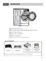
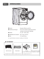
Part 1
SPECIFICATIONS
■ Type : Electric and Gas Dryer
■ Rating : Please refer to the rating label regarding detailed information.
■ Size : 27 x 30.1 x 38.7 inches
■ Capacity : IEC 7.3 cu.ft. (22.5 lb)
■ Weight : 131 Ibs (59.4 kg)
❋ Specifications are subject to change by manufacturer.
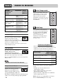
■ ACCESSORIES
❊ Design of pedestals is subject to
change without manafaturers notice.
Dryer Rack
Stacking Kit
See page 27 for instructions. See page 15 for instructions.
Remote Laundry
Monitor
Pedestal
Purchased Separately Purchased Separately
See page 16 for instructions.
3
Part 2
IMPORTANT WARRANTY AND SAFETY INSTRUCTIONS
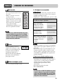
SEEKING WARRANTY SERVICE
The warranty for your dryer is located at the end of this manual. Warranty Service is
available by contacting your nearest LG Service Center. If this product is installed and
operated according to the instructions in this manual, LG will repair or replace any parts
defective in material or workmanship throughout the warranty period, beginning with the
date of purchase.
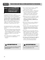
!
WARNING!
For your safety, the recommendations in this manual must be followed. To reduce the risk
of fire or explosion, electric shock or to prevent property damage, personal injury, or death
when using your appliance follow basic precautions.
Warranty Restriction: If the dryer is subjected to other than single family use, all warranty
coverage is effective for only 90 days.
You will need the complete model and serial number when requesting warranty service. proof of
purchase date is required.
Use the space below to record the model number and serial number of your new LG dryer.
Model Number.
Serial Number.
Date of Purchase
❈ Staple your receipt here for convenience when contacting service.
4
Part 2
IMPORTANT WARRANTY AND SAFETY INSTRUCTIONS
IMPORTANT SAFETY INSTRUCTIONS
! WARNING!
To help reduce any risk of electric shock, fire, or other personal injury or property damage when
using your dryer, please exercise care and follow basic safety precautions, including the following:
1) Read all instructions before using the appliance.
2) Do not dry articles that have come into contact with
gasoline, dry-cleaning solvents, or other flammable or
explosive substances, as they give off vapors that could
ignite or explode.
3) Do not allow children to play on or in the appliance.
Close supervision of children is necessary when using
the appliance.
4) Before the appliance is removed from service or
discarded, remove the door to the drying compartment.
5) Do not reach into the appliance if the drum is moving.
6) Do not install or store this appliance where it will be
exposed to the weather.
7) Do not tamper with controls.
8) Do not repair or replace any part of the appliance or
attempt any servicing unless specifically recommended
in the user-maintenance instructions.
9) Do not use heat to dry articles containing foam rubber
or similarly textured rubber-like materials.
10) Clean lint screen before or after each load.
11) Keep area around the exhaust opening and adjacent
surrounding areas free from the accumulation of lint,
dust, and dirt.
12) The interior of the appliance and exhaust duct should
be cleaned periodically by qualified service personnel.
13) Do not place items exposed to cooking oils in your
dryer. Items contaminated with cooking oils may
contribute to a chemical reaction that could cause a
load to catch fire.
14) Do not use fabric softners or products to eliminate
static unless recommended by the manufacturer of the
fabric softner or product.
15) This dryer is designed only for residential use.
SAVE THESE INSTRUCTIONS
USING INSTRUCTIONS
1) Do not put overload into the drum to avoid the poor
drying and wrinkling.
2) Do not over dry fabrics such as knitted fabrics and
flannel.
3) Do not dry items such as elastic bands, plastics,
rubberized items, or sneakers that might melt or ignite
in the dryer.
4) Check the lint filter is in place.
5) Make sure the laundry is not caught when the door is
closed to prevent fabric damage.
6) Check the filter every cycle because a clogged filter is a
fire hazard and affects the efficiency of the dryer.
7) When cleaning the surface of the drum, you should use
a non-abrasive stainless steel cleaner.
8) To prevent a short circuit or penetrating moisture, make
sure the lamp cover is firmly closed.
GROUNDING INSTRUCTIONS
This appliance must be grounded. In the event of
malfunction or breakdown, grounding will reduce the risk
of electric shock by providing a path of least resistance for
electric current. This appliance must be equipped with a
cord having an equipment-grounding conductor and a
grounding plug. The plug must be plugged into an
appropriate outlet that is properly installed and grounded
in accordance with all local codes and ordinances.
Do not modify the plug provided with the appliance.
If it will not fit the outlet, have a proper outlet installed by
a qualified electrician.
This appliance must be connected to a grounded metal,
permanent wiring system or an equipment-grounding
conductor must be run with the circuit conductors and
connected to the equipment-grounding terminal or lead on
the appliance.
WARNING - Improper connection of the equipmentgrounding conductor can result in a risk of electric shock.
Check with a qualified electrician or service person if you
are in doubt as to whether the appliance is properly
grounded.
5
Part 2
!
IMPORTANT WARRANTY AND SAFETY INSTRUCTIONS
WHAT TO DO
IF YOU SMELL GAS:
• Do not try to light a match or cigarette, or turn
on any gas or electrical appliance.
! WARNING!
• Do not touch any electrical switches. Do not
use any phone in your building.
• Keep flammable materials and vapors, such
as gasoline, away from dryer.
• Clear the room, building or area of all
occupants.
• Place dryer at least 18 inches above the floor
for a garage installation.
• Immediately call your gas supplier from a
neighbor’s phone. Follow the gas supplier’s
instructions carefully.
• Failure to do so can result in death,
explosion or fire.
• If you cannot reach your gas supplier, call the
fire department.
!
WARNING
To reduce the risk of fire or explosion, electric
shock, property damage, personal injury or death
when using this appliance, please follow all
instructions and information, including those in
this manual and instructions provided by your
gas supplier.
• Do not store or use any gasoline, dry-cleaning
solvents other flammable vapors or
liquids in the area surrounding this appliance.
• Do not dry anything that has ever had anything
flammable on it, even after washing.
• No washer can completely remove oil. Do not
dry any articles that have ever had any kind of
oil on them, including cooking oil.
• Articles containing foam, rubber, rubber-like
materials, plastic or similar materials should be
air dried.
• Failure to follow these instructions can result in
fire, death or serious injury.
• A qualified service person or company must
perform installation and service of this
appliance.
6
California Safe Drinking Water
and Toxic Enforcement Act
This act requires the governor of California to
publish a list of substances known to the state to
cause cancer, birth defects or other reproductive
harm and requires businesses to warn customers
of potential exposure to such substances.
Gas appliances can cause minor exposure to four
of these substances, namely benzene, carbon
monoxide, formaldehyde and soot, caused
primarily by the incomplete combustion of
natural gas or LP fuels.
Properly adjusted dryers will minimize
combustion. Exposure to these substances can be
minimized further by properly venting the dryer
to the outdoors.
Part 3
INITIAL STEPS FOR INSTALLING YOUR DRYER
The following instructions will help guide you through the initial steps of setting up your dryer for use.
Please note that every section of this manual provides important information regarding the preparation and
use of your dryer, and it is important that you review this entire manual before proceeding with any
installation or use. More detailed instructions concerning electrical connections, gas connections, and
exhaust requirements are provided in other parts of this manual.
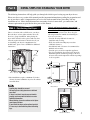
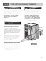
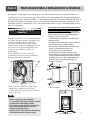
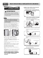
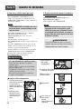
STEP 1 Positioning the Dryer.
Choose a location with a solid floor for your dryer.
Place the dryer at least eighteen inches above the
floor for a garage installation. After placing the
dryer in the desired location, please make sure that
it has the required clearances shown below. If you
are installing your dryer in a manufactured or
mobile home, please refer to STEP 9 for additional
instructions.
49.8”
(126.4 cm)
38.7”
(98.3 cm)
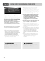
Certain minimum clearances are required
above, behind, and to the sides of the unit, as
shown below. Those required minimum clearances
are set forth in the picture below. Please keep the
following instructions in mind when installing in a
closet or recessed area:
• Consider allowing additional clearance for
installation and servicing.
• Wall, door and floor molding may necessitate
additional clearances.
• An additional inch of clearance is recommended to
minimize noise transfer.
• Consider space needed for companion appliances.
• For closet installations, the picture below shows the
minimum required ventilation openings for the door.
A louvered door with comparable ventilation openings
is also acceptable.
ventilation
hole
27”
(68.6 cm)
30.1”
(76.5 cm)
* Most installations require a minimum 51/2 inches.
(14 cm) clearance behind the dryer for the exhaust
vent with elbow.
Note
ventilation
hole
30.1
76.5
Closet Door
Closet-side View
Leveling legs should be secured.
All four legs are stably placed on a solid and
even floor.
If dryer is not level, laundry may not tumble
properly and sensor will not detect accurate
humidity information.
When leveling, please be cautious not to injure
your fingers and toes.
If you install the dryer on the optional pedstal,
it is nessary to level with the pedestal leveling
legs.
Closet-front View
7
Part 3
INITIAL STEPS FOR INSTALLING YOUR DRYER
Once in position, adjust the leveling legs of the dryer
until it is level from left to right and front to back.
The leveling legs must remain firmly on the floor
and the dryer should not rock. The maximum slope
of the dryer from left to right or front to back should
not exceed 2.5 cm (1 inch). If the dryer is not level,
and if the slope exceeds 2.5 cm (1 inch), a load may
not tumble properly and internal sensors may
malfunction. Note: Other sections of this manual
also provide important information concerning the
placement of and clearances for your dryer. Please
review this entire manual before proceeding with any
installation.
1
STEP
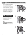
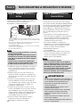
STEP 22: Procedure for
Reversing the Door
The door on your dryer can be installed to open
either to the left or the right. Follow these
instructions to reverse the direction in which your
door opens:
2
Note
Door and latch should be aligned at the center
when closed.
3
8
Part 3
INITIAL STEPS FOR INSTALLING YOUR DRYER
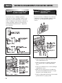
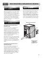
STEP 3 Procedure of Control Panel Change
! WARNING!
• Disconnect power before servicing.
• Replace all parts and panels before operating.
• Be careful of the sharp edge on frame which makes you hurt.
• Failure to follow these instructions can result in death or electrical shock.
Disassemble
1
⚦ Push the cap on the right side of control
panel.
⚧ Remove the screw.
⚨ Slide the control panel to the right about
an inch.
⚨
⚦
Cap
Cap
Control Panel
⚨
4
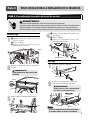
⚦ Push the cap on the right side of lower
cover.
⚧ Remove the screw.
⚨ Slide the lower cover to the right about an
inch.
⚦
Lower, Cover
⚧
⚧
Assemble
2
Push the housing hook and disassemble the
panel.
1
Remove the safety cover.
! WARNING!
Be careful of dropping the control panel.
Safety Cover
Housing
Frame
Hook
2
Attach the housing of control panel until it
clicks into place.
! WARNING!
Make sure that the housing is attached correctly.
If not, the dryer may not operate.
3
Remove the plate by lifting it up slightly.
Frame
Plate
Note
Housing
LG is not responsible for any damages to your
dryer incurred while a customer is changing.
9
Part 3
INITIAL STEPS FOR INSTALLING YOUR DRYER
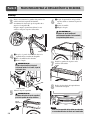
Assemble
Put the hooks of the panel into the left side holes of
frame correctly.
Next the surface of the A is located in the higher
place than the surface of the B.
Then, Push the panel until it is aligned three holes
on the top of the frame.
3
6
⚦ Attach the lower cover in the upper
position where the control panel was
removed.
⚧ Tighten the screw.
⚨ Push the cap.
! WARNING!
Be sure the screw is properly tightened.
If it isn’t the lower cover could come off.
A
B
⚨
⚦
Frame
4
⚧
⚦ Attach the panel by sliding to the left in
clicks into place.
⚧ Turn the screw to the right.
⚨ Close the cap.
! WARNING!
Be sure the screw is properly tightened.
If it isn’t, the control panel could come off.
7
Install the hooks of the plate in the holes
of the frame.
8
Slide the plate to the left until it clicks into
place.
⚦
⚨
Cap
⚧
Control Panel
5
Attach the safety cover.
! WARNING!
Be sure to install the safety cover to
avoid electric shock.
Safety Cover
Note
LG is not responsible for any damages to your
dryer incurred while a customer is changing.
10
Cap
Part 3
INITIAL STEPS FOR INSTALLING YOUR DRYER
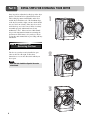
STEP 3 Connecting the Exhaust
and Venting System.
■ ALTERNATE EXHAUST DIRECTIONS
1. Remove screw and exhaust duct.
(Use exhaust kit part #3911EZ9131X.)
! WARNING!
• Use a heavy metal vent.
• Do not use plastic or thin foil duct.
• Failure to follow these instructions can
result in death or fire.
• Clean old ducts before installing this dryer.
Note
The exhaust must be vented to the outside.
Improper taping and incorrect installation will
cause dryer malfunction.
In addition to the following warnings, please refer
to manual section on Exhaust Requirements and
Maintenance. IMPORTANT: To reduce the risk of
fire, combustion, and gas accumulation, the dryer
must be vented to the outdoors. Please follow the
instructions (and all others in this manual) very
carefully.
2-1. Detach and remove the knockout that
matches the desired venting direction
(Right side not available on Gas Dryers)
2-2. Connect a short piece of duct to the
blower housing and attach the duct to
the base.
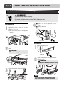
3-1. Insert the male end of a 4" elbow into the
female end of a short duct. Tape the joint.
• Do not use plastic or thin foil duct.
• Use 4" (10.2 cm) diameter rigid or semi-rigid
metal duct (NOTE! Venting materials are not
supplied with the dryer, and you should obtain the
venting materials necessary for proper installation)
• Position the dryer such that the exhaust duct run is
as short as possible.
• Clean old ducts before installing this dryer
• The male end of each section of exhaust duct must
point away from the dryer.
• Use as few elbow joints as possible.
• Use duct tape on all duct joints.
• Insulate ductwork that runs through unheated
areas in order to reduce condensation and lint
build-up on pipe walls.
• PLEASE BE AWARE THAT FAILURE TO
EXHAUST THE DRYER CORRECTLY WILL
VOID THE DRYER’S WARRANTY.
3-2. Insert this assembly elbow first through the
hole in the dryer and push the female end
of the elbow onto the male end of the
blower output shaft. Tape the joint.
11
Part 3
INITIAL STEPS FOR INSTALLING YOUR DRYER
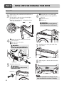
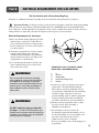
STEP 4 Connection of Gas Supply
STEP 5 Electrical Plug Connections
(Gas dryer only). In addition to the following,
please refer to manual section on Gas Requirements
and Instructions.
Following are several warnings and instructions
concerning making the electrical connection for electric
dryers. More detailed information concerning the
electrical connection is provided in the manual section
entitled Electrical Requirements for Electric Dryer.
It is important that you thoroughly review that section
and the remainder of this manual, before taking any
steps to install or use this dryer.
1
2
5
3
4
1. New stainless steel flexible connector. Use this type of
connector only if allowed by local codes. Use Design AGA
Certified Connector.
2. 1/8" NPT Pipe Plug (for checking inlet gas pressure)
3. Equipment Shut-Off Valve
Installed within 6’ (1.8 m) of dryer.
4. Iron Pipe. Shorter than 20’ (6.1 m)
Use 3/8" pipe.
Longer than 20’ (6.1 m) - Use 1/2" pipe.
5. 3/8" N.P.T. Gas Connection.
Note
Make sure the burner orifice is proper for the type of
gas you have.
For instance, using LPG with LNG orifice will result
in death, fire or explosion. Or using LNG with LPG
nozzle will not allow the burner to ignite.
If needed, orifice conversion should be done by a
qualified service technician and mark or put the
label of the current type of orifice on the dryer.
If changing the orifice, also adjust the gas valve.
1. Confirm that the type of gas available in your laundry
room is appropriate for the dryer. The dryer is prepared
for Natural Gas with a 3/8" NPT gas connection.
2. Remove the shipping cap from the gas connection at the
back of the dryer. Make sure that you don’t damage the
threads of the gas connection pipe when you remove the
shipping cap.
3. Connect the dryer to your laundry room’s gas supply
using a new flexible stainless steel connector (as noted
below, use a new stainless steel flexible connector if
allowed by your local codes).
4. Securely tighten all connections between the dryer and
your laundry room’s gas supply. Turn on your laundry
room’s gas supply and check all pipe connections (both
internal and external) for gas leaks with a non-corrosive
leak detection fluid. Refer to Part 7 (page 20)
5. For LP (Liquefied Petroleum) gas connection, refer to
this manual’s section entitled Gas Requirements and
Instructions.
12
1. Use only a new UL listed No. 10 (copper wire only)
three conductor power supply cord kit rated 240
Volts (minimum) 30 Amperes and labeled as suitable
for use in a clothes dryer.
2. A four-wire cord is required for manufactured
(mobile) home installations and where local codes do
not allow grounding of this appliance through
neutral.
3. Electrical Plug Connections.
4. For additional instruction on connecting the dryer to
an electrical power source, please refer to this
manual’s section on Electrical Requirements and
Electric Dryer.
Note
Burner input requirements
If your house is located at the elevations up to
10,000 feet.
Adjusting burner input setting is not needed at this
elevation because AGA certifies this dryer will not have
any problem with the BTU rating at this altitude.
If your house is above 10,000 feet, you are required to
adjust a four percent (4%) reduction of the burner BTU
rating indicated on the model/serial rating plate.
! WARNING!
• Use a new UL listed 30 amp power supply cord.
• Use a UL approved strain relief.
• Disconnect power before making electrical
connections.
• Connect neutral wire (white or center wire) to
center terminal.
• Ground wire (green or bare wire) must be
connected to green ground connector.
• Securely tighten all electrical connections
• See installation instructions for complete
instructions.
• Failure to do so can result in fire or electrical
shock.
Part 3
INITIAL STEPS FOR INSTALLING YOUR DRYER
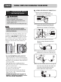
STEP 6 Preparation of the Dryer.
Prior to the first use of this appliance, use allpurpose cleaning products or a solution of detergent
and water, with damp cloth to remove from the
inside of the dryer drum/drying compartment any
dust or dirt that may have accumulated inside the
dryer. Plug-in your dryer after reviewing the
following parts on your dryer’s Electrical
Requirements.
STEP 8 Dryer Airflow.
Effective dryer operation requires appropriate dryer
airflow. The adequacy of the airflow can be
measured by evaluating the static pressure.
Static pressure in the exhaust duct can be measured
with a manometer, placed on the exhaust duct
approximately 2 ft. (60.9 cm) from the dryer.
Static pressure in the exhaust duct should not
exceed 5/8 inches (1.5 cm). The dryer should be
checked while the dryer is running with no load.
Measuring Static pressure
STEP 7 Confirming Heat Source
Operation.
Confirming Heat Source in Gas Dryers
1Manometer
Close the door to the dryer drum/drying
compartment and, after completing all steps in this
manual for proper installation of this dryer, start the
dryer on a heat setting. After the dryer starts, the
igniter will glow red and the main burner will
ignite.
Warning: If all air is not purged from the gas line,
the gas igniter may go off before the gas and the
main burner have ignited. If this happens, the
igniter will re-attempt gas ignition after
approximately two minutes.
Exhaust
Duct
2
Confirming Heat Source in Electric Dryers
Close the door to the dryer drum/drying
compartment and, after completing all steps in this
manual for proper installation of this dryer, start the
dryer on a heat setting. The exhaust air or the
exhaust pipe should be warm after the dryer has
been operating for three minutes.
MAXIMUM STATIC
PRESSURE IN
WATER COLUMN
5/8 inches (1.5 cm)
13
Part 3
INITIAL STEPS FOR INSTALLING YOUR DRYER
STEP 9 Additional Instructions
for Installation of Your
Dryer in a Manufactured
or Mobile Home.
The following instructions are applicable to
installations of the dryer in a manufactured or
mobile home. Any installation in a manufactured or
mobile home must comply with the Manufactured
Home Construction and Safety Standards Title 24
CFR, Part 32-80 or Standard CAN/CSA0Z240 MH
and local codes and ordinances. If you are
uncertain whether your proposed installation will
comply with these standards, please contact a
service and installation professional for assistance.
The following instructions apply to any installation
of the dryer in a manufactured or mobile home:
1) The electrical connection for an electric dryer
must be a 4-wire connection. More detailed
information concerning the electrical connection
is provided at the manual section entitled
Electrical Requirements for Electric Dryer
2) To reduce the risk of combustion and fire, the
dryer must be vented to the outside.
! WARNING!
DO NOT connect exhaust ducts with
metal screws or fasteners that extend
into the duct.
14
3) Electric dryers may be vented to the outside
using the back, left, right, or bottom panel.
4) Gas dryers may be vented to the outside using the
back, left, or bottom panel. Gas dryers may not
be vented to the outside using the right side panel
because of the burner housing.
5) The dryer exhaust duct must be affixed securely
to the manufactured or mobile home structure,
the exhaust duct must be made of a material that
will resist fire and combustion, and it is
recommended that you use a rigid or flexible
metal pipe.
6) DO NOT connect the exhaust duct with any other
duct, vent, chimney, or other exhaust duct.
7) Make sure the dryer has adequate access to
outside fresh air to ensure proper operation. The
opening for outside fresh air must be at least 25
in2 (163 cm2).
8) It is important that the clearance of the duct from
any combustible construction be at least 2 inches
(5 cm), and, when venting the dryer to the
outdoors, the dryer can be installed with a
clearance of 1 inch at the sides and back of the
dryer.
9) Please be aware that venting materials are not
supplied with the dryer. You should obtain the
venting materials necessary for proper
installation.
! WARNING!
DO NOT vent the exhaust duct under the
manufactured or mobile home.
Part 4
ACCESSORIES INSTALLATION
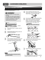
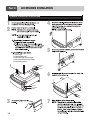
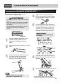
Stacking Kit Installation Instructions
To ensure safe and secure installation, please
observe the instructions below.
! WARNING!
Incorrect Installation can cause serious
accidents.
The weight of the dryer and the height of
installation makes the stacking procedure
too risky for one person. This procedure
should be performed by 2 or more
experienced service personnel.
4
Secure stacking kit side bracket to the
washer with a screw on the back of bracket.
Repeat Steps 2, 3, 4 for the other side.
5
Place the dryer on top of the washer by fitting
legs as shown in the picture. Avoid finger
injuries - be careful not to pinch fingers
between the washer and dryer. Slide dryer
slowly backwards to the stopper of kit.
! WARNING!
Do not stack a washer on the top of the dryer.
Stacking kit
1
2
Place washer firmly on a stable, even and
solid floor.
Peel protective paper off the tape from the
stacking kit side bracket.
Dryer
Washer
3
Fit the stacking kit side bracket firmly to the
side of top plate by attaching the doublesided tape to top plate as picture shows.
6
Insert the front rail. Push the front rail back
to the stoppers of side stacking kit.
7
Attach both sides of the front kit with screws.
Note
Clean the surface before attaching the brackets
and double-sided tape.
• Do not use stacking kit with a gas dryer in potentially
unstable conditions like a mobile home.
15
Part 4
ACCESSORIES INSTALLATION
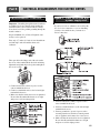
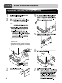
Pedestal Installation Instructions
1
2
4
5
1) Shut off gas.
2) Unplug power cord.
3) Disconnect gas line from dryer.
4) Pull away and loosen vent clamp.
5) Disconnect venting.
for washer/
combo
for dryer
6
for dryer
for washer/
combo
3
16
7
Part 5
ELECTRICAL REQUIREMENTS FOR ELECTRIC DRYERS
The following are additional instructions regarding electrical connections and requirements for electric dryers.
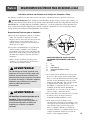
! Important Warning: To help prevent fire, electric shock, serious injury or death, the wiring and grounding
must conform to the latest edition of the National Electrical Code, ANSI/NFPA 70 and all applicable local
regulations. Please contact a qualified electrician to check your home’s wiring and fuses to ensure that your home
has adequate electrical power to operate the dryer.
120V/ 240V, 60 Hertz, 3-Wire Installation
Instructions for Grounding of your Electric
Dryer:
a) This dryer must be connected to a grounded
metal, permanent wiring system or an
equipment-grounding conductor must be run
with the circuit conductors and connected to the
equipment-grounding terminal or lead on the
dryer.
b) The dryer has its own terminal block that must
be connected to a separate 60 Hertz single
phase AC circuit, fused at 30 Amperes (the
circuit must be fused on both sides of the line).
ELECTRICAL SERVICE FOR THE DRYER
SHOULD BE OF MAXIMUM RATE
VOLTAGE LISTED ON THE NAMEPLATE.
DO NOT CONNECT DRYER TO 110, 115,
OR 120 VOLT CIRCUIT. Heating elements are
available for field installation in dryers which
are to be connected to electrical service of
different voltage than that listed on nameplate.
d) The power cord (pigtail) connection between
wall receptacle and dryer terminal block IS NOT
supplied with dryer. Type of pigtail and gauge of
wire must conform to local codes and with
instructions mentioned on the following pages.
e) The method of wiring the dryer is optional and
subject to local code requirements. Refer to
examples on next page.
f) You must select the method by which to wire
your dryer according to local code and ordinance
requirements. Sample methods are included in
the following pages.
c) If branch circuit to dryer is fifteen feet (4.50 m)
or less in length, use U.L. (Underwriters
Laboratories) listed No. 10 A.W.G. wire (copper
wire only), or as required by local codes. If over
fifteen feet (4.50 m), use U.L. (Underwriters
Laboratories) listed No. 8 A.W.G. wire (copper
wire only), or as required by local codes. Allow
sufficient slack in wiring so dryer can be moved
from its normal location when necessary.
17
Part 5
ELECTRICAL REQUIREMENTS FOR ELECTRIC DRYERS
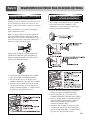
Review the following options to determine the appropriate electrical connection
for your home:
4-wire receptacle
(NEMA type14-30R)
Use the instructions in this section if your home has
a 4-wire receptacle (NEMA type 14-30R) and you
will be using a UL listed, 120/240 volt minimum,
30 amp, dryer power supply cord.
3-wire receptacle
(NEMA type10-30R)
Use the instructions in this section if your home has
a 3-wire receptacle (NEMA type 10-30R) and you
will be using a UL listed, 120/240 volt minimum,
30 amp, dryer power supply cord.
4-wire direct
If this type is available at your home. you will be
connecting to a fused disconnect or circuit breaker
box.
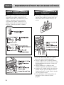
4-wire connection : Direct wire
Important : Grounding through the neutral conductor
is prohibited for (1) new branch-circuit installations,
(2) mobile homes, (3) recreational vehicles, and (4)
areas where local codes prohibit grounding through the
neutral conductor.
Prepare minimum 5 ft (1.52 m) of length in order for
dryer to be replaced.
First, peel 5 inches (12.7 cm) of covering material from
end. Strip 5 inches of ground wire insulation. After
cutting 11/2 inch (3.8 cm) from 3 other wires peel
insulation back 1 inch (2.5 cm). Make ends of 3 wires a
hook shape.
Then, put the hooked shape end of the wire under the
screw of the terminal block (hooked end facing to the
right) and pinch the hook together and screw tightly.
3-wire direct
If this type is available at your home. you will be
connecting to a fused disconnect or circuit breaker
box.
Note
• Connect the power supply wire to the terminal
block. Colored wire should be connected to
same color screw. Wire color indicated on
manual is connected to the same color screw in
block. Otherwise,a short or excessive current
flow may result.
18
1. Connect neutral wire (white) of power cord to center
terminal block screw.
2. Connect red and black wires to the left and right
terminal block screws.
3. Connect ground wire (green) of power cord to external
ground screw and move neutral ground wire of
appliance and connect it to center screw.
4. Make sure that the strain relief screw is tightened.
Be sure that all terminal block nuts are on tight and
power cord is in right position.
Part 5
ELECTRICAL REQUIREMENTS FOR ELECTRIC DRYERS
3-wire connection : Direct wire
Important : Grounding through the neutral conductor
is prohibited for (1) new branch-circuit installations,
(2) mobile homes, (3) recreational vehicles, and (4)
areas where local codes prohibit grounding through the
neutral conductor.
Option 1: 4-wire connection with
a power supply cord.
• lf your local codes or ordinances do not allow the
use of a 3-wire connection, or you are installing
your dryer in a mobile home, you must use a
4-wire connection.
Prepare minimum 5 ft (1.52 m) of length in order
for dryer to be replaced.
First, strip 3 1/2 inches (8.9 cm) of outer sheath from
end and strip 1 inch of insulation from each
conductor.
Then, put the hooked shape end of the wire under
the screw of the terminal block (hooked end facing
rightward) and pinch the hook together and tighten
the screw securely.
1. Connect neutral wire (white) of power cord to
center terminal block screw.
2. Connect red and black wires to the left and right
terminal block screws.
3. Make sure that the strain relief screw is tightened.
Be sure that all terminal block nuts are on tight
and power cord is in right position.
1. Connect neutral wire (white) of power cord to
center terminal block screw.
2. Connect red and black wires to the left and right
terminal block screws.
3. Connect ground wire (green) of power cord to
external ground screw and move neutral ground
wire of appliance and connect it to center screw.
4. Make sure that the strain relief screw is tightened.
Be sure that all terminal block nuts are on tight
and power cord is in right position.
19
Part 5
ELECTRICAL REQUIREMENTS FOR ELECTRIC DRYERS
Option 2: 3-Wire connection with
a power supply cord.
lf your local codes or ordinances permit the
connection of a frame-grounding conductor to the
neutral wire, use these instructions. If your local
codes or ordinances do not allow the connection of
a frame-grounding conductor to the neutral wire,
use the instructions under Section 1: Optional 3wire connection.
Option 3: Optional 3-wire
connection.
• If your local codes or ordinances do not allow the
connection of a frame-grounding conductor to the
neutral wire, use the instructions under this
section.
Section 1
1. Connect neutral wire (white) of power cord to
center terminal block screw.
2. Connect ground wire of appliance and neutral
wire of power cord to center terminal block
screw.
3. Connect red and black wires to the left and right
terminal block screws.
4. Make sure the strain relief screw is tightened.
Be sure that all terminal block nuts are on tight
and power cord is in right position.
5. Connect a independent ground wire from external
ground connector to proper ground.
20
Part 6
ELECTRICAL REQUIREMENTS FOR GAS DRYERS
120 Volt, 60 Hertz, with 3-Prong Grounding Plug
Following are additional instructions regarding electrical connections and requirements for gas dryers.
!
Important Warning: To help prevent fire, electric shock, serious injury or death, the wiring and grounding
must conform to the latest edition of the National Electrical Code, ANSI/NFPA 70, or the Canadian Electrical
Code, CSA C22.1, and all applicable local regulations. Please contact a qualified electrician to check your home’s
wiring and fuses to ensure that your home has adequate electrical power to operate the dryer.
Electrical Requirements for Your Dryer:
a) Please note that the wiring diagram is provided
inside the dryer control hood. Label all wires
prior to disconnection when servicing the dryer,
because wiring errors can cause serious injury to
you and your dryer.
b) Your dryer is designed to be used on a separate
branch, polarized, three-wire, effectively
grounded, 120 Volt, 60 Hertz, AC (alternating
current) circuit protected by a 15 Ampere fuse,
equivalent fuse or circuit breaker.
c) Use separately fused circuits for washers and
dryers, and DO NOT operate a washer and a
dryer on the same circuit.
! WARNING!
Do not overload the circuit by operating
other appliances on the same circuit when
this appliance is operating, by using an
extension cord to connect the dryer to the
power source, or by using any adapter to
allow additional cords to connect to the
same outlet.
! WARNING!
DO NOT modify the plug provided with
the dryer. If it does not fit the outlet in your
laundry room, a proper outlet will need to be
installed in your laundry room by a qualified
service person or company.
STANDARD 120 VOLT, 60 HERTZ, 3-WIRE
EFFECTIVELY GROUNDED CIRCUIT
1
2
3
4
5
L1
Ground
Neutral Side
Round Grounding Prong
Neutral
a) The dryer has a three-prong plug to help guard
against shock. The plug should be plugged
directed into a properly grounded three-prong
receptacle that is rated 120 Volts AC (alternating
current) 15 Amps. This plug, in order to be
properly and fully effective, must be plugged into
a properly installed outlet that is grounded in
accordance with all local codes and ordinances.
b) The dryer must be grounded in order to reduce
the risk of electric shock, including a
malfunction or breakdown.
c) If your laundry room does not meet the
specifications required by this manual, or if you
are uncertain whether or not your laundry room
meets these specifications, please have a
qualified service person or company.
Review your laundry room’s electrical supply for
any problems.
21
Part 7
GAS REQUIREMENTS AND INSTRUCTIONS
Following are important instructions and information concerning the requirements for the gas supply and service for
gas dryers.
! Important Warning: The gas supply and service for a gas dryer must comply with all local codes
and ordinances. In the absence of any local codes or ordinances in your area, the gas supply and service for your gas
dryer must comply with the latest edition of the National Fuel Gas Code, ANSI Z223.1/NFPA 54.
1. Gas supply requirements: Liquefied Petroleum
(L.P.) Gas (2,500 Btu/ft3 (93.1 MJ/m3)) service
must be provided at 10 + 1.5 in. water column
pressure.
2. Do not attempt to connect the dryer to Liquified
Petroleum (LP Gas) Gas service without a
qualified professional.
3. Isolate the dryer from the gas supply piping
system by closing its individual manual shut-off
valve during any pressure testing of the gas
supply system at test pressure equal to or less
than 2/1 psi (3.45 kPa).
4. Supply Line Requirements. Your laundry room
must have a rigid gas supply line to your dryer.
In the United States, an individual manual shutoff
valve MUST be installed within at least 6 feet
(1.8 m) of the dryer, in accordance with the
National Fuel Gas Code ANSI Z223.1. A 1/8 in.
N.P.T. pipe plug must be installed as shown.
5. If using a rigid pipe, the rigid pipe should be 1/2
inch IPS. If acceptable under local codes and
ordinances and when acceptable to your gas
supplier, 3/8 inch approved tubing may be used
where lengths are less than 20 feet (6.1 m).
Larger tubing should be used for lengths in
excess of 20 feet (6.1 m). It is also important that
you use pipe joint compound that is insoluble in
LP gas.
6. To reduce the danger of gas leaks, explosion, and
fire, please follow and observe the following
instructions and WARNINGS.
• Connect the dryer to the type of gas shown on the
nameplate.
• Use new flexible stainless steel connectors.
• Use Teflon tape and pipe joint compound
insoluble in LP gas on all pipe threads.
• Purge gas supply of air and sediment before
connecting the gas supply to the dryer in order to
prevent gas valve contamination. Before
tightening connection between gas supply and
dryer, purge remaining air until odor of gas is
identified.
• DO NOT use an open flame to inspect for gas
leaks; instead use a non-corrosive leak detection
fluid.
! WARNING!
DO NOT attempt any disassembly of the
dryer. Any disassembly requires the
attention and tools of an authorized and
qualified service person or company.
22
! WARNING!
• Use a new AGA or CSA approved gas
supply line.
• Install a shut-off valve.
• Securely tighten all gas connections.
• If connected to LP, have a qualified person
make sure gas pressure does not exceed
13 in. water column.
• Examples of a qualified person include
licensed heating personnel, authorized gas
company personnel, and authorized service
personnel.
• Failure to do so can result in death,
explosion, or fire.
Part 8
EXHAUST REQUIREMENTS AND MAINTENANCE
Following are important instructions and information concerning the exhaust requirements for your dryer.
! Important Warning: To reduce the risk of fire, combustion, or accumulation of combustible gases, DO NOT
exhaust dryer air into an enclosed and unventilated area, such as an attic, wall, ceiling, crawl space, chimney, gas
vent, or concealed space of a building. To reduce the risk of fire, DO NOT exhaust the dryer with plastic or thin foil
ducting.
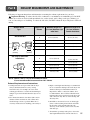
Weather Hood
Type
Number of 90°
Elbows
Recommended
4”
4”
(10.2 cm)
(10.2 cm)
Use Only for Short Run
Installations
Maximum length of 4”
(10.2 cm) diameter rigid
metal duct
Maximum length of 4”
(10.2 cm) diameter
flexible metal duct
0
65 feet (19.8 m)
45 feet (13.7 m)
1
55 feet (16.8 m)
35 feet (10.7 m)
2
47 feet (14.3 m)
30 feet (9.1 m)
3
36 feet (11.0 m)
25 feet (7.6 m)
4
28 feet (8.5 m)
20 feet (6.1 m)
0
55 feet (16.8 m)
35 feet (10.7 m)
1
47 feet (14.3 m)
27 feet (8.2 m)
2
41 feet (12.5 m)
21 feet (6.4 m)
3
30 feet (9.1 m)
17 feet (5.2 m)
4
22 feet (6.7 m)
15 feet (4.5m)
2-1/2”
(6.35 cm)
NOTE : Deduct 6 feet (1.8 m) for each additional elbow.
It is not recommended to use more than 4 90° elbows.
Exhaust Requirements and Instructions:
1. Venting materials are not provided with the dryer
and you should obtain the necessary venting
materials locally. For example, the outer end of
exhaust pipe must have a weather hood with hinged
dampers to prevent back-draft when the dryer is not
in use.
2. The exhaust duct must be four inches (10.2 cm) in
diameter with no obstructions. The exhaust duct
should be kept as short as possible. Make sure to
clean any old ducts before installing your new dryer.
3. Rigid or semi-rigid metal ducting is recommended
for use as transition ducting between the dryer and
and the wall. In special installations when it is
impossible to make a connection with the above
recommendations, then a UL-listed flexible metal
transition duct may be used between the dryer and
wall connection only. The use of this ducting will
affect dry time.
4. DO NOT use sheet metal screws on exhaust pipe
joints or other fastening means which extend into
the duct that could catch lint and reduce the
efficiency of the exhaust system. Secure all joints
with duct tape.
5. To maximize operating results, please observe the
duct length limitations noted in the chart above. 2 3
Part 8
EXHAUST REQUIREMENTS AND MAINTENANCE
Exhaust and Dryer Maintenance
! WARNING!
Disconnect the dryer’s electric power
prior to any cleaning or maintenance.
1. After one year of use, the interior and complete
exhaust system of the dryer should be examined
and cleaned if necessary.
2. Before one year of use, when drying performance
has become unsatisfactory, please examine and
clean the exhaust duct for better drying
performance.
3. Check the weather hoods frequently to ensure
the dampers are moving freely, that the dampers
are not pushed in and that nothing has been set
against the dampers.
4. A qualified service person or company should be
used to perform this maintenance.
5. A Flexible Metal Vent Kit, available at extra cost,
can be used to exhaust the dryer when it is placed
in hard to reach places. This Kit comes in two
pieces, one of which is attached to the dryer and
the other is attached to the wall exhaust outlet.
Following attachment of the two separate pieces
to the dryer and the wall, the dryer may be
returned to its final position, after which the two
pieces themselves can be connected.
7. Ordinarily, the dryer drum will need no care.
Wipe the exterior of the dryer as required, and
always wipe the exterior of the dryer in the event
any detergent, bleach, or other washing products
is spilled on the dryer.
8. Clean the control panel with a damp cloth as
necessary. Warning: spray pre-wash products
may damage the finish of the control panel.
9. Please clean the lint filter either before drying
each load or after drying each load.
10. Always make sure the lint filter is clean before
starting a new load, because a clogged lint filter
may increase drying times.
11. Annually remove the lint filter and attach it to
the vacuum duct. See item #2 above.
12. Please note that the wiring diagram is provided
inside the dryer control hood. Label all wires
prior to disconnection when servicing the dryer,
because wiring errors can cause serious injury
to you and your dryer.
24
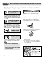
Cleaning the Lint Screen
1. Clean the lint filter either before drying each load
or after drying each load. Always make sure the
lint filter is clean before starting a new load,
because a clogged lint filter may increase drying
times.
2. To clean, pull the lint screen straight up and roll
any lint off the screen with your fingers.
Do not rinse or wash screen to remove lint. Push
the lint screen firmly back into place.
3. Always ensure the lint screen is firmly secured
before running the dryer. Running the dryer with
a loose lint screen may cause overheating and
damage to the dryer and articles being dried.
4. Some articles of clothing may shed more lint than
others (towels for example), causing the lint
screen to fill rapidly. Remove lint from the lint
screen before and after drying these articles, such
as new towels.
5. In the event lint falls off of the lint screen and
into the dryer during removal, inspect the exhaust
hood and remove any lint.
6. Laundry detergent and fabric softener residue can
build up on the lint screen, causing longer drying
times. The screen is likely blocked if lint falls off
the screen. In order to prevent this type of build
up, and help ensure proper operation of your
dryer, clean the lint screen with a nylon brush
every six months or, if necessary, more
frequently. The lint filter can also be washed as
follows:
a) After rolling the lint off of the screen with your
fingers, wet both sides of the screen with hot or
warm water.
b) Wet a nylon brush with hot water and liquid
detergent and scrub the lint screen with the brush
to remove the buildup of detergent and fabric
softener.
c) After the residue has been removed, rinse screen
with hot water.
d) After drying the lint screen with a clean towel,
firmly replace the lint screen in your dryer.
Part 9
OPERATING YOUR DRYER
Following are instructions for starting and using your new dryer. Please refer to specific sections of this manual for
more detailed information. Important Warning: To reduce the risk of fire, electric shock, or injury to person, read
this entire manual, including the Important Safety Instructions, before operating this dryer.
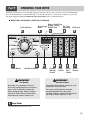
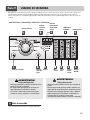
■ DLE9577WM / DLG9588WM / DLE9577SM / DLG9588SM
Cycle Selection
Power Button
Status, Check Filter,
Est. Time
Time Change Drying, Cooling,
Wrinkle Care
Remaning
Button
Start/Pause Button
! WARNING!
Fire Hazard
No washer can completely remove oil.
Do not dry anything that has ever had any
type of oil on it (including cooking oils).
Items containing foam, rubber, or plastic
must be air dried. Failure to follow these
instructions can result in death or fire.
Beeper
Dryness
Intensity
Control
Temp.
Control
Child Lock
Drying Option
Time
Buttons
Control
! WARNING!
Explosion Hazard
Keep flammable materials and vapors, such
as gasoline, away from dryer.
Do not dry anything that has ever had
anything flammable on it (even after
washing). Failure to follow these instructions
can result in death, explosion, or fire.
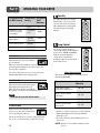
1 Power Button
• Use this button for power on or off.
25
Part 9
OPERATING YOUR DRYER
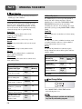
2 Cycle Selection
• Turn the knob to select the desired cycle based on
laundry types and conditions.
1. Sensor Dry Cycles
Sensor Dry Cycles allow you to match the cycle to
the load you are drying. Each cycle dries certain
fabrics at the recommended temperature. A sensor
detects the moisture in the load and automatically
adjusts the drying time for optimal drying
Heavy Duty
Use for drying heavy fabrics such as jeans,
corduroys or work clothes.
Cotton/Towels
Use for drying denims, towels, heavy cottons.
Normal
Use for drying sturdy fabrics such as work casual
clothes.
Perm. Press
Use for permanent press and synthetic items.
Delicates
Use for drying synthetic fabrics, washable knit
fabrics and no-iron finishes.
Ultra Delicate
Use for drying gentle items such as workout wear,
shear and lace items.
Sensor Dry Preset Cycle Settings
Time*
(Minutes)
Sensor Dry
Cycles Load Type
Temp.
HEAVY DUTY
Jeans, heavy weight
High
COTTON/TOWELS
Towel, denim pants
Medium
High
55
NORMAL
Work clothes, corduroys
Medium
41
PERM. PRESS
Synthetics , permanent
press
Low
36
DELICATES
Lingerie, sheets, blouses
Low
32
ULTRA DELICATE
Shear, workout wear
and lace items
Ultra
Low
34
26
2. Manual Dry Cycles
Use Manual Cycles to select a specific amount of
drying time and a drying temperature. When a
Manual Cycle is selected, the ESTIMATED TIME
REMAINING display shows the actual time
remaining in your cycle. You can change the actual
time in the cycle by pressing MORE TIME or LESS
TIME.
Speed Dry
Use for small loads or loads that need a short drying
time.
Freshen Up
Use this cycle to remove wrinkles from items, such
as clothes packed in a suitcase or items wrinkled
from being left in the dryer too long.
Air Dry
Use the Air Dry Modifier for items that require
drying without heat such as rubber, plastic and heatsensitive fabrics.
Manual Preset Cycle Settings
Manual Dry
Cycles Load Type
Temp.
Default Time*
(Minutes)
SPEED DRY
SMALL LOADS
High
25
FRESHEN UP
Remove Wrinkles
Medium
High
20
AIR DRY
Air Dry
30
54
3 Time Change Button
• Press MORE TIME or LESS TIME until the
desired drying time is set.
Note
Time change button is available only with Manual
Dry, Time Dry and Rack Dry programs.
Part 9
OPERATING YOUR DRYER
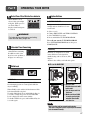
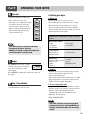
4 Status/Clean Filter/Wrinkle Care Indicator
• When Wrinkle Care is
selected, this option light
will glow. When power is
on, Check Filter is
displayed until start/pause
is selected.
!
WARNING!
For better drying performance and safety,
clean lint filter every single use.
7 Option Buttons
1. CUSTOM PROGRAM.
Set up your favorite combination of
settings and save them here for onetouch recall.
1. Select a cycle.
2. Change DRY LEVEL and TEMP. CONTROL.
3. Select OPTIONS you want.
4. Press and hold the CUSTOM PROGRAM.
To recall your stored CUSTOM PROGRAM
Press CUSTOM PROGRAM button, then press
START/PAUSE.
5 Estimated Time Remaining
• The display shows the
estimated time remaining.
In addition to this, if the
dryer has some problem, it
displays error messages.
6 Child Lock
2. Rack Dry
Rack Dry is designed for use with
items which are not designed for
tumble drying such as sweaters, silk or
lingerie.
Sneakers also will dry well with this option.
■ To use the RACK DRY
1
2
1. Child Lock
Child Lock can be used to prevent your children
from changing options on control panel while the
dryer is running.
3
When Child Lock is enabled, all the buttons will be
locked and Child Lock glows.
To enable Child Lock, Press and hold Rack Dry for
3 seconds, A single beep tone is heard and Child
Lock is displayed on the status window.
To disable Child Lock, press and hold Rack Dry for
3 seconds again.
1.Open the door.
Hold the dryer rack with
both hands.
2. Put the dryer rack into
the drum.
3. Make sure Dryer RACK
is evenly spaced right
onto the drum inside
and door rim.
Note
Don’t use the rack for normal tumble drying.
The rack is shipped in place in your dryer so remove
rack for normal laundry.
27
Part 9
OPERATING YOUR DRYER
Suggested Items Temperature Suggested
for Rack Drying Setting
Time*
(Minutes)
Washable wool items
Low
20
Stuffed toys with
cotton or polyester
fiber filling
Low/Ultra
Low
20/30
Stuffed toys, foam
rubber filled.
Air Dry/
Ultra Low
50/30
Foam rubber pillows
Air Dry
50
Athletic shoes
Air Dry
20
* Reset time as needed to complete drying.
3. Wrinkle Care
This option helps to prevent wrinkles
in your laundry.
8 Time Dry
Use Time Dry Option to change
Drying Time on your own. You
can select the desired operation
time manually by pressing Time
Dry button between 20 to 60
minutes.
9 Temp. Control
Use Temp. Control Option to
select temperatures for the Manual
Cycles. Press TEMP. CONTROL
until the desired temperature
setting glows. Temperature
modifiers cannot be used with the
Sensor Dry Cycles.
When you select the wrinkle free option, the dryer
will periodically tumble for up to three hours after
the cycle has completed.
You can use this option in case you can not remove
laundry immediately after drying is done.
4. Anti Bacterial
This option reduces bacteria by using
high temperature during the cycle.
This option can only be used with the
Heavy Duty, Cotton/Towels and Normal cycles.
Note
When Using Air Dry
This chart shows examples of items that can be
dried using AIR DRY.
Type of Load
Default Time*
(Minutes)
Foam rubber-pillows,
padded bras, stuffed toys
20 - 30
Plastic shower curtains,
tablecloths
20 - 30
Rubber-backed rugs
40 - 50
Olefin, polypropylene,
shear nylon
10 - 20
Do not use this cycle with delicate fabrics.
5. Damp Dry Beep
When you select the damp dry beep
option, a beep will alert you when your
load is approximately 80% dry.
This notice will allow you to remove lightweight items
that are dry or other items that you may wish to iron.
28
Reset cycle to complete drying, if needed.
• Check to see that coverings are securely stitched.
• Shake and fluff pillows by hand periodically
during the cycle.
• Dry item completely. Foam rubber pillows are
slow to dry.
NOTE: Air Dry is not available with Sensor Dry
Cycles.
Part 9
OPERATING YOUR DRYER
10 Dry Level
❁ Starting your dryer
• Use these buttons to set dry level
• First, select sensor dry cycle.
• Select dry level to adjust how much
you want to dry the load. As the
cycle runs, the control senses the
dryness of the load and adjusts the
time automatically based on the
selected dryness level.
1. Before use
• Clean lint screen before or after each cycle.
• Place laundry into dryer and shut door. See Loading.
• Turn the knob to select the drying cycle you want.
The preset setting for Sensor Dry Cycles or Manual
Cycles will glow. The estimated or actual cycle time (in
minutes) will show in the display.
Following are sample loads for Super Capacity
Dryers:
Note
DRY LEVEL selections can only be made while
using Sensor Dry Cycles. Selecting
MORE Dry or LESS Dry automatically adjusts the
needed time which is already sensed.
11 Beeper
The BEEPER controls the volume
of the beep that is made when you
press any of the buttons on the
control panel.
Press BEEPER to adjust the sound level or turn off
the signal.
12 Start / Pause Button
• Use this button for start or pause.
Heavy Work Clothes
4 jeans
4 workpants
4 work shirts
2 sweatpants
2 sweatshirts
Cotton/Towels
10 bath towels
10 hand towels
14 wash cloths
Mixed Load
3 sheets (1 king, 2 twin) 9 T-shirts
9 shorts
4 pillowcases
10 handkerchiefs
3 shirts
3 blouses
2. Loading
• Determine load size by the amount of space the load
requires rather than the weight of the load.
• Avoid overloading the dryer.
Following these instructions can help reduce your utility
bill, prolong the life of your clothes, and decrease the
likelihood of uneven drying and wrinkle.
3. To use a sensor dry cycle
• Select DRY LEVEL to adjust how dry you want
the load. As the cycle runs, the control senses the
dryness of the load and adjusts the time
automatically for the selected dryness level.
• Select the desired options.
• Press START/PAUSE
Note
DRY LEVEL selections can only be made while
using Sensor Dry Cycles. Selecting MORE Dry or
LESS Dry automatically adjusts the sensed time
needed.
29
Part 9
OPERATING YOUR DRYER
4. To use a manual dry cycle
• Select a Manual Dry Cycle.
• Press MORE TIME or LESS TIME until the
desired drying time is displayed. Tap MORE TIME
or LESS TIME and the time will change by 1
minute interval.
5. Pausing or restarting
• To pause the dryer at any time:
Open the door or press START/PAUSE.
• To restart the dryer
Close the door. Press START/PAUSE.
Note
Note
The MORE TIME or LESS TIME feature can be used
with Manual Dry, Time Dry and Rack Dry Cycles.
Drying will continue from where the cycle
was interrupted if you close the door and press
START within 10 minutes. If the cycle is
interrupted for more than 10 minutes, the dryer
will shut off. Select new cycle settings before
restarting the dryer.
• Press TEMP. CONTROL until the desired
temperature indicator glows.
• (OPTIONAL STEP) If desired, select OPTIONS.
For more details, see Options.
• Press START/PAUSE. Be sure the door is closed.
• If you do not press START/PAUSE within 10
minutes of selecting the cycle, the dryer
automatically shuts off.
• If you wish to end your drying cycle after pressing
START/PAUSE, press START/PAUSE again.
To stop your dryer at any time
Press START/PAUSE or open the door.
Maintenance
Clean lint filter
Clean the lint filter after each use and check it
before use. Not cleaning or emptying the filter
will increase drying time and energy
consumption, therefore dryer life expectancy
could be shortened after all.
■ Clean the door and its opening
1. Wipe out the door
opening. Otherwise,
build-ups of dirty and
foreign objects will
damage sealing of
door.
2. Clean the transparent
glass door to keep
inside view clear
through the glass.
30
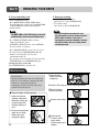
1.Open the door
and pull the filter
straight up.
2.Clean the filter using one of the following methods.
Run the fingers
across the filter.
Vacuum the lint filter.
Wash the lint
screen in warm,
soapy water.
Dry thoroughly and
replace.
Part 10
TROUBLESHOOTING GUIDE
Troubleshooting Tips
Save time and money! Review the charts on the following
pages first and you may not need to call for service.
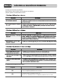
1. Problem: My Dryer Won’t Start
Question
What to Do
• Is the dryer plugged in?
Confirm that the dryer’s plug is securely and completely pushed into the laundry
room’s power outlet.
• Is the fuse blown, or is the circuit
breaker tripped?
Check your home’s or laundry room’s fuse box/circuit breaker box and replace the
fuse or reset the circuit breaker. (IMPORTANT: electric dryers generally use two
fuses or breakers.)
2. Problem: My Dryer Doesn’t Heat
Question
What to Do
• Is the fuse blown, or is the circuit
breaker tripped?
If the fuse is blown or the circuit breaker tripped, the dryer might tumble but not
heat. Check your home’s or laundry room’s fuse box/circuit breaker box and replace
the fuse or reset the circuit breaker. (IMPORTANT: electric dryers generally use
two fuses or breakers.)
• Is the gas supply or service
blocked or off?
Confirm that the house gas shutoff and the dryer gas shutoff are both fully open.
3. Problem: There Are Greasy Spots On My Clothes.
Question
What to Do
• Did you follow the instructions on
your fabric softener product?
Confirm and follow the instructions provided with your fabric softener product.
• Are you drying clean and dirty
clothes together?
Make sure to use your dryer to dry only clean items, because dirty items can soil
clean clothes placed in the same load or later placed in the dryer drum.
• Were your clothes entirely clean?
Stains on dried clothes are actually stains that weren’t cleansed during the washing
process. Please review and confirm that you are following your washing
instructions and that the clothes are being completely cleaned.
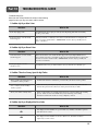
4. Problem: My Dryer Displayed An Error Code.
Question
What to Do
tE1
It is displayed when thermistor is open. In this case, thermistor should be replaced
and call a service center.
tE2
It is displayed when thermistor is shorted. In this case, thermistor should be
replaced by a service center.
31
Part 10
TROUBLESHOOTING GUIDE
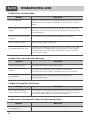
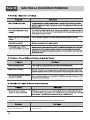
5. Problem: There Is Lint On My Clothes
Question
What to Do
• Is your lint filter full?
Please refer to the manual section on cleaning the lint filter, and please confirm that the
lint filter is clean. It is important that the lint filter is clean before each new load of
laundry.
• Did you properly sort your load of
laundry?
In order to reduce the amount of lint in a load of laundry, sort lint producers (like a
fuzzy white cotton towel) separately from clothes that might catch lint (such as a pair
of black linen pants).
• Do your clothes have excess static
electricity?
See comments below under. There Is Static In My Clothes After Drying.
• Did you overload your dryer?
Divide your larger load into smaller loads.
• Did you place any paper, tissue, or
other similar material in the load?
Sometimes a person might forget to take a piece of paper or a tissue out of a pocket,
and this paper, tissue, or similar material can cause excess lint in a load of laundry.
Confirm that the pockets of pants, shirts, and other articles of clothing are empty
before washing and drying.
6. Problem: There Is Static In My Clothes After Drying
Question
What to Do
• Did you use fabric softener?
Try using a fabric softener to reduce static electricity.
• Did you over dry the load of
laundry?
Over-drying a load of laundry can cause a build up of static electricity.
Try using a fabric softener or adjust your settings and use a shorter drying time.
• Are you drying synthetic, permanent
press and blends?
These materials can cause static to build up in a load of dried clothes.
Try using a fabric softener.
7. Problem: The Drying Time Is Not Consistent
Question
• Are you using consistent heat
settings and consistent load sizes?
What to Do
The drying time for a load will vary depending on the heat setting, the type of heat
used (electric, natural or LP gas), the size of the load, the type of fabrics, the wetness
of the clothes and the condition of the exhaust ducts and lint filer.
8. Problem: Water Is Found Around The Cabinet Cover When Opening The Door.
Question
• Is water found around cabinet cover
when opening the door?
32
What to Do
It is not out of order because this is condensed moisture by drying.
Part 10
TROUBLESHOOTING GUIDE
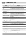
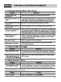
9. Problem: It Takes Too Long For My Clothes To Dry
Question
What to Do
• Did you properly sort your loads of
laundry?
Separate heavy weight items from light weight items when creating loads.
• Are you drying large loads of heavy
fabrics?
Heavy fabrics take longer to dry because they tend to retain more moisture. To help
reduce and maintain more consistent drying times for large and heavy fabrics,
separate these items into smaller loads of a consistent size.
• Are the dryer controls properly set?
Use the appropriate control settings for the type of load you are drying.
• Is the lint filter clean before each
new load of laundry?
Please confirm that the lint filter is clean prior to each new load of laundry.
• Are the exhaust ducts clear and
properly configured?
Confirm through review of the appropriate sections of this manual that the exhaust
venting ductwork is properly configured. Confirm that the venting is free of
obstructions. Confirm that the outside wall dampers are moving freely, that the
dampers are not pushed in, and that nothing has been set against the dampers.
• Is the fuse blown, or is the circuit
breaker tripped?
Check your home’s or laundry room’s fuse box/circuit breaker box and replace the
fuse or reset the circuit breaker. (IMPORTANT: electric dryers generally use two
fuses or breakers.)
• Did you overload your dryer?
Divide your larger load into a number of smaller loads.
• Did you under load your dryer?
If you are only drying a handful of items, add a few extra pieces to help ensure
proper tumbling action.
10. Problem: My Clothes Are Wrinkled
Question
What to Do
• Are you over drying your laundry?
Over drying a load of laundry can lead to wrinkled clothes. Try a shorter drying
time, and remove items while they still retain a slight amount of moisture.
• Are you removing your laundry
from the dryer soon after the
drying cycle is complete?
Remove your laundry from the dryer after the drying cycle ends and either hang or
fold the items.
11. Problem: My clothes are shrinking
Question
• Are you following the care
instructions for your garment?
What to Do
To avoid shrinkage, please carefully follow the care and use instructions for your
garment, because some fabrics will naturally shrink when washed. Other fabrics
can be washed but will shrink when dried in a dryer.
12. Problem: RLM (Remote Laundry Monitor)
Question
• RLM problem
What to Do
See the Owner’s Manual of RLM & PLC modem.
33
LG DRYER LIMITED WARRANTY – USA
34
CARACTERÍSTICAS DEL PRODUCTO
1
DESEMPEÑO EXTRAORDINARIO
Sin mencionar su incomparable gran capacidad, puede beneficiarse por su Eficiencia en tiempo, operaciòn silenciosa
y su sistema de ahorro de energìa.
2
TINA DE ACERO INOXIDABLE
Las tinas de acero inoxidable no se oxidan por naturaleza asì que el òxido nunca se presentarà en sus prenda.
3
DISEÑO ARTÍSTICO
Atractivo y moderno panel frontal y gran puerta de cristal limpio para ue su secadora tenga el mejor aspecto.
4
CUIDADO DIGITAL DE LOS TEJIDOS
Calentador con control de la temperatura multinivel para cuidar mejor sus prendas más queridas.
5
FACILIDAD DE USO
Una amplia selección de funciones sencillas de usar para facilitar la operación de la secadora.
6
USO DEL RLM (MONITOR REMOTO DE LA SECADORA)
El RLM controla el estado de su lavadora y/o secadora. Puede conectar la unidad de visualización en cualquier toma
de su casa. La Unidad de Visualización RLM puede comprarse separadamente para esta secadora.
7
CONTROL ADAPTABLE
El panel de control puede estar en posición superior o inferior para permitir el fácil acceso bien en paralelo o sobre
una lavadora.
8
SELECCIONES CON UN BOTÓN
Para seleccionar una opción, presione una vez el botón. No es necesario presionar los botones varias veces para
desplazarse por una lista de opciones.
Qué significa secado por sensor o secado por tiempo?
Su secadora le proporciona la posibilidad de programar acciones de secado por sensor o por tiempo.
Secado por sensor
La secadora detectará automáticamente la humedad de la colada y determinará el tiempo de funcionamiento necesario
basándose en el nivel de sequedad de la carga y el programa seleccionado. En ocasiones, podrá observar un incremento
o disminución repentinos del tiempo de operación. Si esto ocurriera, será debido a que el sensor detecta la humedad de
la colada dentro de un período de tiempo determinado. Un cambio repentino en el tiempo de operación no significa un
mal funcionamiento.
Secado por tiempo
Significa que puede programar el tiempo de operación manualmente para completar el secado. Alternativamente, puede
usar esta función para secar la ropa si las prendas aún están húmedas pese a haber terminado un ciclo de secado.
El secado por tiempo es más efectivo cuando tenga prendas pesadas u objetos voluminosos como sábanas de camas
tamaño superdoble o ropa de trabajo gruesa.
CONTENIDO
PARTE 1. ESPECIFICACIONES. ............................................................................................................................................................................................................3
PARTE 2. GARANTÍA E INSTRUCCIONES DE SEGURIDAD IMPORTANTES....................................................................................................................................4
PARTE 3. PASOS INICIALES PARA LA INSTALACIÓN DE SU SECADORA.. ...................................................................................................................................7
PARTE 4. INSTALACIÓN DE ACCESORIOS.......................................................................................................................................................................................15
PARTE 5. REQUERIMIENTOS ELÉCTRICOS PARA SECADORA ELÉCTRICA............... ................................................................................................................17
PARTE 6. REQUERIMIENTOS ELÉCTRICOS PARA SECADORAS A GAS....................... ...............................................................................................................21
PARTE 7. REQUERIMIENTOS E INSTRUCCIONES SOBRE EL GAS ...............................................................................................................................................22
PARTE 8. REQUERIMIENTOS Y MANTENIMIENTO SOBRE EL ESCAPE........................................................................................................................................23
PARTE 9. USANDO SU SECADORA ...................................................................................................................................................................................................25
PARTE 10. GUÍA PARA LA SOLUCIÓN DE PROBLEMAS.............................................. ..................................................................................................................31
GARANTÍA LIMITADA DE LA SECADORA LG ...................................................................................................................................................................................34
2
Parte 1
ESPECIFICACIONES
■ Nombre
: Secadora Eléctrica y de Gas
■ Suministro de Energìa
: Favor de consultar la etiqueta de medición
referente a la información detallada.
■ Tamaño
: 27 x 30.1 x 38.7 inches
■ Capacidad de la Secadora : IEC 7.3cu.ft. (22.5 lb)
■ Peso
: 131 Ibs (59.4 kg)
Las especificaciones son sujetas a cambio por el fabricante.
■ ACCESORIOS
Parrilla de secado
Vea la página 27 para su uso
Kit para Apilar
Vea la página 15 para su uso
Pedestal
Monitor remoto de la colada
comprado separadamente Se adquiere por separado
Vea la página 16 para su uso
3
Parte 2
GARANTÍA E INSTRUCCIONES DE SEGURIDAD IMPORTANTES
BÚSQUEDA DE ASISTENCIA SOBRE LA GARANTÍA
Encontrará la garantía de su secadora en la parte final de este manual. El servicio de
garantía está disponible contactando con su Centro de Servicio LG más próximo. Si este
producto se instala y se opera siguiendo las instrucciones de este manual, LG reparará o
recambiará cualquier pieza defectuosa en material o mano de obra a lo largo del período
cubierto por la garantía, comenzando desde el día de compra.
!
ADVERTENCIA!
Para su seguridad, debe seguir las recomendaciones de
este manual. Para reducir el riesgo de incendio o explosión, o choque eléctrico, o para
prevenir daños a la propiedad, lesiones personales, o muerte cuando use su artefacto, siga
las precauciones básicas, incluyendo las siguientes.
Restricción de la Garantía : Si la secadora es utilizada para otro propósito que no sea el uso
familiar privado, toda cobertura de la garantía es efectiva por sólo 90 días.
Necesitará el número de modeloo y de serie completo al solicitar la garantía de servicio. Es necesaria
la prueba de la compra (ticket o recibo).
Utilice el siguiente espacio para anotar el número de modelo y de serie de su nueva secadora LG.
Modelo Número
Número de Serie
Fecha de Adquisición
❈ Tenga a mano su ticket de compra por comodidad al contactar con el servicio de atención al
cliente.
4
Parte 2
GARANTÍA E INSTRUCCIONES DE SEGURIDAD IMPORTANTES
INSTRUCCIONES DE SEGURIDAD IMPORTANTES
!
ADVERTENCIA!
Para ayudar a reducir el riesgo de choque eléctrico, incendio, o lesión personal o
daño a la propiedad cuando use su secadora, por favor sea precavido y siga las
precauciones de seguridad básicas, incluyendo las siguientes:
1) Lea todas las instrucciones antes de usar el artefacto.
2) No seque artículos que hayan estado en contacto con
gasolina, solventes para lavado en seco, o cualquier otra
sustancia inflamable o explosiva, ya que despiden vapores
que pueden incendiarse o explotar.
3) No permita que los niños jueguen sobre o dentro del
artefacto Es necesario que supervise de cerca a los niños
cuando utiliza el artefacto.
4) Antes de que el artefacto sea removido del servicio o
desechado, quite la puerta del compartimiento de secado.
5) No meta la mano en el aparato si el tambor está en
movimiento.
6) No instale o almacene este artefacto donde esté expuesto a
la intemperie.
7) No fuerce los controles.
8) No repare o reemplace ninguna pieza del artefacto ni
intente darle servicio a menos que esté específicamente
recomendado en las instrucciones de mantenimiento para
el usuario.
9) No use calor para secar artículos que contengan hule
espuma o materiales de textura similares al hule.
10) Limpie la malla para pelusas antes o después de cada
carga.
11) Mantenga el área alrededor de la abertura de escape y las
áreas adyacentes libres de acumulación de pelusa, polvo y
sucio.
12) El interior del artefacto y el ducto de escape deben ser
limpiados periódicamente por personal de servicio
calificado.
13) No coloque artículos que hayan sido expuestos a aceite de
cocina dentro de la secadora. Artículos contaminados con
aceite de cocina pueden contribuir a una reacción química
causante de incendiar una carga.
14) No use suavizantes de telas o productos para eliminar la
estática a menos que sea recomendado por el fabricante
de estos productos.
15) Esta secadora ha sido diseñada únicamente para uso
doméstico.
GUARDE ESTAS INSTRUCCIONES
UTILIZANDO LA INSTRUCCIÓNES
1) No sobrecargue el tambor, a fin de evitar un mal secado o
arrugado excesivo.
2) No seque durante demasiado tiempo telas tejidas y franela.
3) No introduzca en la secadora elementos de plástico, bandas
elásticas, caucho o zapatillas, que podrían derretirse o
prender fuego.
4) Compruebe que el filtro de pelusa e hilo está en posición.
5) Asegúrese de que la ropa no quede pillada por la puerta al
cerrar la máquina, a fin de evitar daños en la tela.
6) Compruebe el filtro después de cada ciclo, ya que un filtro
obstruido constituye un peligro de incendio y afecta
gravemente la eficacia de la secadora.
7) Al limpiar la superficie del tambor, utilice un limpiador no
abrasivo especial para acero inoxidable.
8) Para evitar posibles cortocircuitos o la entrada de
humedad, asegúrese de que la tapa está firmemente
cerrada.
INSTRUCCIONES DE CONEXIÓN A TIERRA
Este artefacto debe estar conectado a tierra. En caso de mal
funcionamiento o avería, la conexión a tierra reduce el riesgo
de choque eléctrico al proveer una ruta de menor resistencia a
la corriente eléctrica. Este artefacto está equipado con un
cordón que contiene un conductor equipo-tierra y un enchufe
con conexión a tierra. El enchufe debe ser conectado a un
tomacorriente adecuado, debidamente instalado y conectado a
tierra de acuerdo con todos los códigos locales y ordenanzas.
Verifique con un electricista calificado o un técnico de
servicio si tiene alguna duda si el artefacto está debidamente
conectado a tierra.
No modifique el enchufe suministrado con el artefacto; si éste
no encajase en el tomacorriente, haga que le instalen un
tomacorriente adecuado por un electricista calificado.
ADVERTENCIA- Una incorrecta conexión del conductor
equipo-tierra puede resultar en un riesgo de choque eléctrico.
5
Parte 2
!
GARANTÍA E INSTRUCCIONES DE SEGURIDAD IMPORTANTES
QUE HACER EN CASO DE OLER
GAS:
• No intente encender un fósforo, o cigarrillo, o
encender ningún artefacto de gas o eléctrico.
• No toque ningún interruptor eléctrico. No use
ningún teléfono en su casa o edificio.
• Evacúe la habitación, edificio o el área de
todos los ocupantes.
• Llame inmediatamente a su proveedor de gas
desde el teléfono de un vecino. Siga
cuidadosamente las instrucciones de su
proveedor de gas.
! ADVERTENCIA!
• Mantenga los materiales y vapores
inflamables, como la gasolina, lejos de la
secadora.
• Coloque la secadora al menos 18 pulgadas
sobre el piso para instalación en el garaje.
• Si no cumple con estas instrucciones puede
resultar en muerte, explosión o incendio.
• Si no puede contactar a su proveedor de gas,
llame al departamento de bomberos.
!
ADVERTENCIA
Para reducir el riesgo de incendio o explosión,
choque eléctrico, daño a la propiedad, lesiones
personales, o muerte cuando use este artefacto, por
favor siga todas las instrucciones e información,
incluyendo las de este manual y las instrucciones e
información suministradas por su proveedor de
gas, incluyendo las siguientes:
• No almacene o use gasolina, solventes para
lavado en seco, o cualquier otro vapor o líquido
inflamable en el área adyacente a este artefacto.
• No seque nada que alguna vez haya tenido
contacto con algo inflamable, aún después de
lavarlo.
• Ninguna lavadora puede remover completamente
el aceite. No seque ningún artículo que haya
tenido contacto con cualquier clase de aceite,
incluyendo aceite de cocinar.
• Artículos que contienen espuma, hule, materiales
similares al hule, plástico, o materiales similares
deben secarse en el tendedero o utilizando el
ciclo de aire.
• La falta de cumplimiento de estas instrucciones
puede resultar en incendio, muerte o lesiones
serias.
• Un técnico o una compañía calificada debe
efectuar la instalación y proveer el servicio a este
artefacto.
6
Agua libre para Beber de California
y Acto de Aplicaciòn Tòxica
Este decreto exige al gobernador de California
publicar una lista de substancias conocidas por
el estado por causar cáncer, defectos congénitos
o cualquier otro daño reproductivo y exige a los
negocios a advertir a sus consumidores sobre la
posible exposición a dichas substancias.
Aparatos a gas pueden causar una exposición
menor a cuatro de estas substancias, a saber
benceno, monóxido de carbono, formaldehído y
hollín, causadas principalmente por la
combustión incompleta de gas natural o
combustibles de petróleo licuado.
Secadoras debidamente ajustadas minimizarán la
combustión. La exposición a estas substancias
puede ser minimizada más allá, ventilando
adecuadamente la secadora a la intemperie.
Parte 3
PASOS INICIALES PARA LA INSTALACIÓN DE SU SECADORA
Las siguientes instrucciones le servirán de guía a través de los pasos iniciales para la preparación de su
secadora para el uso. Por favor note que cada sección de este manual proporciona información importante
sobre la preparación y uso de su secadora, y es muy importante que lea este manual completamente antes de
proceder con cualquiera instalación o con su uso. Instrucciones detalladas adicionales concernientes a las
conexiones eléctricas, conexiones del gas, y los requerimientos sobre el escape son suministrados en otras
partes de este manual.
PASO 1 Colocación de la
Secadora
Elija un lugar de suelo sólido en el que poder ubicar
su secadora. Colóquela al menos 18 pulgadas sobre
el suelo si la instala en un garaje. Una vez la
secadora ha sido instalada en el lugar deseado,
asegúrese de que cuenta con las holguras necesarias
que puede ver en la siguiente ilustración y en las
secciones de los requisitos de salida y de
mantenimiento.
Si está instalando su secadora en una casa
prefabricada o móvil, favor refiérase al PASO 9
abajo para instrucciones adicionales.
Son necesarias ciertas holguras mínimas de separación
arriba, por debajo y a los lados de la unidad, como puede
apreciar en las ilustraciones siguientes. Las holguras
mínimas necesarias son las que marcan las ilustraciones de
abajo. Recuerde siempre las instrucciones siguientes al
instalar en un recinto cerrado o hueco.
• Considere dejar más holgura para la instalación y las
tareas de servicio.
• La existencia de protuberancias en la pared, puerta o el
suelo puede necesitar de holguras mayores.
• Se recomienda un pulgada adicional de holgura para
reducir al mínimo la transferencia de ruido.
• Considere el espacio necesario para los
electrodomésticos que puedan acompañar a éste.
• En las instalaciones en recintos cerrados, la ilustración
de abajo muestra las aberturas de ventilación mínimas
necesarias para la puerta. Es aceptable también una
puerta con rendijas con aberturas para lograr una
ventilación comparable.
49.8”
(126.4 cm)
Agujero de
Ventilación
38.7”
(98.3 cm)
27”
(68.6 cm)
Agujero de
Ventilación
30.1”
(76.5 cm)
* La mayoría de las instalaciones requieren un
mínimo de 51/2 pulgadas de espacio libre
(14 cm) detrás de la secadora para el conducto de
escape con el codo.
30.1
76.5
Puerta del Clóset
Vista lateral del Clóset
Nota
Debería asegurar las patas niveladoras.
Las cuatro patas deben quedar sentadas con total
seguridad en un suelo sólido y nivelado.
Si la secadora no está nivelada, la colada podría
no dar vueltas debidamente y el sensor no
detectará la humedad correcta.
Al ajustar el nivel, tenga cuidado de no lesionarse
seriamente los dedos de la mano ni del pie.
Vista Frontal del Clóset
7
Parte 3
PASOS INICIALES PARA LA INSTALACIÓN DE SU SECADORA
Una vez en posición ajuste las patas niveladoras de la
secadora hasta que esté nivelada de izquierda a
derecha y del frente hacia atrás. Las patas
niveladoras deben permanecer firmes en el piso y la
secadora no debe mecerse. La máxima inclinación de
la secadora de izquierda a derecha o del frente hacia
atrás no debe ser mayor de 2.5 cm (1 pulgada). Si la
secadora no está nivelada, y si la inclinación excede
los 2.5 cm (1 pulgada), la carga puede que no gire
adecuadamente y los sensores internos pueden no
funcionar correctamente. Nota: Otras secciones de
este manual también proveen información importante
sobre la ubicación y los espacios libres para su
secadora.Por favor lea este manual completamente
antes de proceder con cualquier instalación.
PASO 2 Procedimiento para
Invertir la Puerta
1
2
La puerta de su secadora puede ser instalada de
manera que abra hacia la izquierda o hacia la
derecha. Siga estos procedimientos para invertir la
dirección en que su puerta abre:
Nota
La puerta y la bisagra deberían alienarse en el
centro al cerrarse. De lo contrario la puerta se
cerrará y abrirá mal.
3
8
Parte 3
PASOS INICIALES PARA LA INSTALACIÓN DE SU SECADORA
PASO 3 Procedimiento de cambio del panel de control
! ADVERTENCIA!
• Desconecte la alimentación antes de iniciar tareas de reparación.
• Vuelva a instalar todas las piezas y paneles antes de volver a iniciar el funcionamiento.
• Tenga cuidado con las aristas cortantes del bastidor, podrían ser causa de lesiones.
• No acatar estas instrucciones puede resultar en causas de muerte o descarga eléctrica.
Desmontaje
Empuje el tapón hacia el lado derecho del
panel de control.
Retire el tornillo.
Deslice el panel de control aprox. una
pulgada hacia la derecha.
1
4
Empuje el tapón del lado derecho de la
tapa inferior.
Retire el tornillo.
Deslice la tapa inferior aprox. una
pulgada hacia la derecha.
Tapón
Tapón
Panel de control
Cubierta inferior
Montaje
2
Empuje el gancho de la carcasa y desmonte
el panel.
1
Desmonte la tapa de seguridad.
! ADVERTENCIA!
Tenga cuidado de no dejar caer el panel
de control.
Tapa de seguridad
Carcasa
Bastidor
Gancho
2
Acople la carcasa del panel de control en
posición hasta escuchar un chasquido.
! ADVERTENCIA!
Asegúrese de que la carcasa esté correctamente instalada.
De lo contrario, la secadora podría no funcionar.
3
Retire la placa levantándola ligeramente.
Bastidor
Placa
Nota
Carcasa
LG no será responsable de los daños ocasionados a
su secadora mientras el cliente está cambiando.
9
Parte 3
PASOS INICIALES PARA LA INSTALACIÓN DE SU SECADORA
Montaje
3
Inserte correctamente los ganchos del panel en los
orificios del lado izquierdo del bastidor.
A continuación, observará que la superficie A es
superior a la superficie B.
Después empuje el panel hasta alinear los tres
orificios en la parte superior del bastidor.
6
Acople la tapa inferior en la posición
superior donde se desmontó el panel de
control.
Apriete el tornillo.
Empuje el tapón.
! ADVERTENCIA!
Asegúrese de que el tornillo esté
correctamente apretado. De lo contrario,
la tapa inferior podría caerse.
A
B
Tapón
Bastidor
4
Acople el panel deslizándolo hacia la
izquierda hasta escuchar un chasquido.
Gire el tornillo hacia la derecha.
Cierre el tapón.
! ADVERTENCIA!
Asegúrese de que el tornillo bajo el tapón esté
correctamente apretado. De lo contrario, el panel de
control podría caerse.
7
Instale los ganchos de la placa en los
orificios del bastidor.
8
Deslice la placa hacia la izquierda hasta
escuchar un chasquido.
Tapón
Panel de control
5
Monte la tapa de seguridad.
! ADVERTENCIA!
Asegúrese de instalar la tapa de seguridad
para evitar posibles descargas eléctricas.
Tapa de
seguridad.
Nota
LG no será responsable de los daños ocasionados
a su secadora mientras el cliente está cambiando.
10
Parte 3
PASOS INICIALES PARA LA INSTALACIÓN DE SU SECADORA
PASO 3 Conexión del Sistema
de Escape y Ventilación
■ DIRECCIONES ALTERNAS PARA EL ESCAPE
1. Quite el tornillo y el ducto de escape.
(Utilice el kit de salida, n° de pieza 3911EZ9131X).
!
ADVERTENCIA!
• Utilice material para ventilación de metal pesado.
• No utilice conductos de plástico o aluminio delgado.
• Si no cumple con estas instrucciones puede resultar
en muerte o incendio.
2-1.
Nota
El extremo de la ventilación mirará hacia el lado
externo y el mal roscado o una instalación.
inestable de la ventilación provocarán niveles de
secado no deseados.
Además de las siguientes advertencias, por favor
refiérase a la sección del manual sobre Requerimientos y
Mantenimientodel Escape. IMPORTANTE: Para
reducir el riesgo de incendio, combustión y acumulación
de gas, la secadora debe estar ventilada hacia la
intemperie. Por favor siga las siguientes instrucciones
(y todas las otras en este manual) muy cuidadosamente.
Separe y extraiga la seguridad de la parte inferior,
izquierda o derecha según desee. (La ventilación
del lado derecho no está disponible en la
secadora a gas). ①, ②, ③ es el orden del trabajo.
Parte A
Golpe de gracia
2-2. Reconecte el otro conducto (11 pulgadas o 28 cm)
al alojamiento del soplador y acople el conducto a
la base.
Cinta cobertora del ducto
3-1. Arme previamente un codo de 4 con un ducto de 4".
• No utilice conductos de plástico o aluminio.
• Utilice ducto rígido o semi-rigidos de metal de 4"
(10.2 cm) de diámetro (nota: Los materiales para
ventilación no son suministrados con la secadora, y usted
debe obtenerlos por separado para una adecuada
instalación)
• Coloque la secadora en tal posiciòn que el ducto corra de
la menor forma posible.
• Limpie los ductos viejos antes de instalar esta secadora.
• El extremo macho de cada sección del ducto de escape
debe apuntar contrario a la secadora.
• Use las menores conyucturas posibles.
• Utilice cinta selladora de ductos en todas las uniones de
ductos.
• Aísle la instalación de escape que pase a través de áreas sin
calentamiento con el fin de reducir la condensación y la
acumulación de pelusas en las paredes de la tubería; y
• POR FAVOR TENGA CUIDADO YA QUE DE NO
INSTALAR CORRECTAMENTE EL SISTEMA DE
ESCAPE ANULARÁ LA GARANTÍA DE LA
SECADORA
Envuelva la cinta selladora para ducto alrededor de la
unión.
Cinta cobertora del ducto
3-2. Inserte el montaje del ducto, el codo primero a
través de la abertura lateral y conecte el codo al
ducto interno de la secadora.
Cinta cobertora del ducto
11
Parte 3
PASOS INICIALES PARA LA INSTALACIÓN DE SU SECADORA
PASO 4 Conexión del Suministro
de Gas
(Secadora a Gas solamente). Además de lo siguiente, por
favor refiérase a la sección del manual sobre
Requerimientos e Instrucciones del Gas.
1
2
5
3
4
1. Conector flexible nuevo de acero inoxidable. Utilice este tipo de conector
sólo si es permitido por los códigos locales. Use un conector de diseño AGA
Certificado.
2. Conector de tubo NPT de 1/8" (para verificar la presión de entrada de gas)
3. Válvula de Cierre de Equipo instalada a una distancia de
6’ (1.8 m) de la secadora.
4. Tubería de hierro. Más corta de 20’ (6.1 m) Use tubería de 3/8" . Más larga
de 20’ (6.1 m) - Use tubería de 1/2".
5. Conexión de Gas N.P.T de 3/8" .
Nota
Asegúrese de que la boquilla del zumbador es la adecuada
para el tipo de gas que utiliza.
Por ejemplo, usar LPG con una boquilla LNG ocasionaría la
muerte del usuario, el incendio o una explosión. Del mismo
modo, LNG con una boquilla LPG no provocarán la ignición
del quemador.
Si fuese necesario, la conversión de la boquilla debería
realizarla un técnico de servicio cualificado y marcar o poner
la etiqueta del tipo actual de boquilla en la secadora.
1. Confirme que el tipo de gas disponible en su cuarto de
lavado sea el adecuado para su secadora. La secadora
está preparada para Gas Natural con una conexión de
gas NPT de 3/8".
2. Remueva la tapa protectora de la conexión de gas
detrás de la secadora. Asegúrese de no dañar la rosca
de la tubería de la conexión de gas cuando remueva la
tapa protectora.
3. Conecte la secadora al suministro de gas en su cuarto
de lavado utilizando un conector nuevo flexible de
acero inoxidable (como se mencionó antes, sólo use un
conector nuevo flexible de acero inoxidable si es
permitido por códigos locales)
4. Asegúrese de apretar todas las conexiones entre la
secadora y el suministro de gas en su cuarto de lavado.
Abra el suministro de gas en su cuarto de lavado y
verifique todas las conexiones de la tubería (internas y
externas) para detectar fugas de gas utilizando un
detector líquido de fugas no corrosivo.
5. Para una conexión a gas LP (Petróleo Licuado),
refiérase a la sección de este manual sobre
Requerimientos e Instrucciones del Gas.
12
PASO 5 Electrical Plug Connections
Conecciòn Elèctrica
A continuación encontrará advertencias e instrucciones
concernientes a la confección de la conexión eléctrica
para secadoras eléctricas. Información detallada adicional
concerniente a la conexión eléctrica es suministrada en la
sección del manual Requerimientos Eléctricos para la
Secadora Eléctrica y es importante que usted lea esta
sección completamente, así como el resto del manual,
antes de tomar algún paso para instalar o usar esta
secadora.
1. Use solamente un cordón de alimentación nuevo
listado No. 10 por U.L.(alambre de cobre únicamente)
de tres conductores clasificado para 240 Voltios
(mínimo) 30 Amperios y que está indicado de uso
aceptable para una secadora de ropa.
2. Un cordón de 4 alambres es requerido para
instalaciones y uso en casas prefabricadas (móvil) y
donde los códigos locales no permitan conexión a
tierra de este aparato a través del neutral.
3. Electrical Plug Connections
Conecciòn Elèctrica.
4. Para instrucciones adicionales de como conectar la
secadora a una fuente eléctrica, favor refiérase a la
sección de este manual sobre Requerimientos
Eléctricos para Secadora Eléctrica.
Nota
Requisitos de admisión al quemador
Si su casa está situada en alturas hasta los 10.000 pies.
Ajustar la admisión al quemador no es necesario en estas
elevaciones porque A.G.A. certifica que esta secadora no
tiene problemas con los rangos BTU a estas alturas.
Si su casa está situada a alturas superiores a los 10.000
pies, necesitará ajustar un cuatro por cien (4%) de
reducción en el quemador, que es el rango indicado por el
BTU en la placa de modelo/rango de serie.
! ADVERTENCIA!
• Use un cordón de alimentación nuevo aprobado por
U.L. de 30 amp.o alambre de cobre sólido calibre 10.
• Use un liberador de tensión aprobado por UL .
• Desconecte la corriente antes de hacer las
conexiones eléctricas.
• Conecte el alambre neutral (alambre blanco o
central) al terminal central.
• El alambre a tierra alambre verde o descubierto)
debe conectarse al conector a tierra verde.
• Asegúrese de apretar todas las conexiones
eléctricas.
• Vea las instrucciones de instalación para unas
instrucciones completas.
• De no seguir estas advertencias puede resultar en
incendio o choque eléctrico.
Parte 3
PASOS INICIALES PARA LA INSTALACIÓN DE SU SECADORA
PASO 6 Preparación de la
Secadora
Antes de usar por primera ves esta secadora, utilice
un producto limpiador para todo propósito, o una
solución de detergente y agua, con un paño húmedo
para remover de la parte interior del tambor de la
secadora /compartimiento de secado cualquier polvo
o sucio que se haya podido acumular dentro de la
secadora. Enchufe su secadora después de haber
revisado las siguientes partes en los Requerimientos
Eléctricos de su secadora.
PASO 7 Confirmación de la Operación
de la Fuente de Calor.
PASO 8 Flujo de Aire
La efectiva operación de la secadora requiere de un
flujo de aire adecuado. El flujo de aire adecuado
puede ser medido evaluando la presión estática. La
presión estática en el ducto de escape puede ser
medida con un manómetro, colocado en el ducto de
escape aproximadamente a a 2 pies (60.9 cm) de la
secadora. La presión estática en el ducto de escape
no debe exceder 5/8 pulgadas (1.5 cm). La secadora
debe ser verificada cuando está operando sin carga.
Medición de la Presión Estática.
Confirmación de la Fuente de Calor en
Secadoras a Gas
1Man ó ro
Cierre la puerta al tambor / compartimiento de
secado de la secadora y después de haber
completado todos los pasos de este manual para la
instalación correcta de esta secadora, encienda la
secadora en temperatura caliente, como mejor se
describe en las instrucciones de operación provistas
con la secadora. Después que la secadora se
enciende, el encendedor resplandecerá en rojo y el
quemador principal encenderá.
Advertencia: Si no todo el aire es purgado fuera de
la línea de gas, el encendedor podría apagarse antes
de que el gas y el quemador principal se hayan
encendido. Si esto sucede, el encendedor intentará
encender el gas después de aproximadamente dos
minutos.
Confirmación de la Fuente de Calor en
Secadoras Eléctricas
Ducto
2 de Escape
PRESIÓN ESTÁTICA
MÁXIMA EN
COLUMNA DE AGUA
5/8 pulgadas (1.5 cm)
Cierre la puerta al tambor / Compartimiento de
secado de la secadora y después de haber
completado todos los pasos en este manual para una
instalación correcta de esta secadora, encienda la
secadora en temperatura caliente, como mejor se
describe en las instrucciones de operación provistas
con la secadora. El aire de escape o el tubo de
escape deben calentarse después que la secadora
haya operado por tres minutos.
13
Parte 3
PASOS INICIALES PARA LA INSTALACIÓN DE SU SECADORA
PASO 9 Instrucciones Adicionales
para la Instalación de su
Secadora en una Casa
Prefabricada o Móvil.
Las siguientes instrucciones se aplican a
instalaciones de la secadora en casas prefabricadas o
móvil. La instalación en una casa prefabricada o
móvil debe cumplir con los estándares de Seguridad
y Construcción de Casas Prefabricadas, Título 24
CFR, Parte 32-80 o el Estándar CAN/CSA0Z240
MH y los códigos y ordenanzas locales. Si no está
seguro de que la instalación cumplirá con estos
estándares, por favor contacte a un profesional de
mantenimiento e instalación para que le ayude.
Las siguientes instrucciones se aplican a cualquier
instalación de la secadora en una casa prefabricada
o móvil:
1) La conexión eléctrica para una secadora eléctrica
debe ser de conexión de 4 alambres. Información
adicional detallada concerniente a la conexión
eléctrica es suministrada en la sección del manual
Requerimientos Eléctricos para la Secadora
Eléctrica.
2) Para reducir el riesgo de combustión e incendio,
la secadora debe estar ventilada hacia la
intemperie.
! ADVERTENCIA!
NO conecte los ductos de escape con tornillos
de metal o sujetadores que se extiendan
dentro del ducto.
14
3) Las secadoras eléctricas pueden ser ventiladas
hacia el exterior usando el panel trasero,
izquierdo, derecho o inferior.
4) Las secadoras a gas pueden ser ventiladas hacia
el exterior usando el panel trasero, izquierdo o
inferior. Las secadoras a gas no pueden ser
ventiladas al exterior usando el panel del lado
derecho debido a la cubierta del quemador.
5) El ducto de escape de la secadora debe estar fijo
a la estructura de la casa prefabricada o móvil, y
el ducto de escape debe estar hecho de un
material que resista fuego y combustión, y es
recomendable que utilice una tubería de metal
flexible o rígido.
6) NO conecte el ducto de escape con ningún otro
ducto, ducto de ventilación, chimenea u otro
ducto de escape.
7) Asegúrese que la secadora tenga un buen acceso
al aire fresco del exterior para una operación
adecuada. La abertura para el aire fresco del
exterior debe ser de por lo menos 25 pulgadas
(163 cm).
8) Es importante que el espacio libre del ducto de
cualquier construcción combustible sea de por lo
menos 2 pulgadas (5 cm), y cuando ventila la
secadora hacia la intemperie, la secadora puede
ser instalada con un espacio libre de 1 pulgada a
los lados y en la parte posterior de la secadora.
9) Favor notar que los materiales para la ventilación
no son provistos con la secadora. Usted debe
obtener los materiales para la ventilación
necesarios para una adecuada instalación.
! ADVERTENCIA!
NO ventile el ducto de escape hacia abajo
de la casa prefabricada o móvil.
Parte 4
INSTALACIÒN DE ACCESORIOS
Instrucciones de Instalaciòn para montar el Kit
Para asegurar una instalaciòn segura, por favor
observe las instrucciones siguientes.
! ADVERTENCIA!
Una intalaciòn incorrecta puede causar accidentes
serios.
El peso de la secadora y la altura de la instalaciòn
hacen que montar el kit sea peligroso para una
sola persona.
Este procedimiento debe realizarse por 2 o màs
personas con experiencia en este tipo de
servicios.
4
Asegure el kit en el soporte lateral a la
lavadora con un tornillo en la parte trasera
del soporte. Repita los pasos 2,3,4 para el
otro lado.
5
Coloque la secadora en la parte superior de la
lavadora asegurando las patas como se muestra
en el dibujo. Evite daños en los dedos- tenga
cuidado en que no se queden atrapados sus
dedos entre la lavadora y la secadora. Deslice
lentamente la secadora hasta el final del kit.
! ADVERTENCIA!
No coloque la lavadora en la parte superior
de la secodora.
Kit para Apilar
1
Coloque la lavadora firmemente en una
superficie estable y sòlida como las
instrucciones del Manual de Usuario
indican.
2
Quite el papel protector del kit en el soporte
lateral.
Secadora
Lavadora
3
Encaje el soporte lateral del kit en el lado
de la parte superior de la plataforma
anexàndole la cinta doble cara en la
plataforma como muestra El dibujo.
6
Inserte la parte frontal del kit. Empuje la
parte frontal hasta el final de los soportes
laterales.
7
Atornille los lados de la parte frontal del kit.
Nota
Limpie la superficie antes de acoplar las
abrazaderas y la cinta de doble cara.
• No use el kit si existe secado de gas en
condiciones Inestables como una casa mòvil.
15
Parte 4
INSTALACIÒN DE ACCESORIOS
Instalacion de la secadora (Cinta de tipo doble-cara)
1
2
4
5
B. Desinstalación de una secadora a gas:
1) Cierre el gas.
2) Desenchufe el cable de alimentación.
3) Desconecte la línea de gas de la secadora.
4) Deje a un lado y afloje la brida de ventilación.
5) Desconecte la ventilación.
lavadora/combo
lavadora/combo
3
16
6
7
Parte 5
REQUERIMIENTOS ELÉCTRICOS PARA SECADORAS ELÉCTRICAS
Las siguientes son instrucciones adicionales sobre las conexiones y requerimientos eléctricos para las secadoras
eléctricas.
! Advertencia Importante: Para ayudar a prevenir incendios, choque eléctrico, lesiones serias o muerte,
el cableado y la conexión a tierra deben estar de acuerdo con la edición más reciente del código Eléctrico
Nacional, ANSI/NFPA 70 y todas las regulaciones locales aplicables. Por favor contacte a un electricista calificado
para verificar el cableado y fusibles de su casa y para asegurar que tiene la energía eléctrica adecuada para el
funcionamiento de la secadora.
120V/ 240V, 60 Hertz, Instalación de 3-Alambres
Instrucciones para la Conexión a Tierra de
su Secadora Eléctrica:
a) Por favor note que el diagrama de cableado está
localizado dentro de la cubierta del control de la
secadora.
b) Esta secadora debe ser conectada a un metal
con conexión a tierra, sistema de cableado
permanente, o un conductor equipo-tierra debe
correr con los conductores de circuito y estar
conectado al terminal equipo-tierra o línea
principal de la secadora.
c) La secadora tiene su propia caja terminal la cual
debe estar conectada a una línea separada,
60 Hertz, circuito de fase sencilla, circuito AC
(corriente alterna), con fusible de 30 Amperios
(el circuito debe tener fusibles en ambos lados
de la línea). EL SERVICIO ELÉCTRICO
PARA LA SECADORA DEBE SER DEL
MÁXIMO RANGO DE VOLTAJE DESCRITO
EN LA PLACA. NO CONECTE LA
SECADORA A UN CIRCUITO DE 110, 115,
Ó 120 VOLTIOS. Hay elementos calefactores
disponibles para secadoras que se conectarán a
servicios eléctricos de diferente voltaje que los
que se listan en la placa, tal como de 208
voltios.
e) La conexión del cordón de alimentación (cable
flexible) entre el tomacorriente y la caja terminal
de la secadora NO ES suministrada con la
secadora. El tipo del cable flexible y el calibre del
alambre deben estar conforme con los códigos
locales y con las instrucciones de las páginas
siguientes.
f) El método de cableado de la secadora es opcional
y sujeto a los requerimientos del código local.
Refiérase a los ejemplos en la próxima página.
g) Usted debe seleccionar el método para cablear su
secadora de acuerdo a los requerimientos de los
códigos locales y ordenanzas. Métodos de
ejemplo están incluidos en las siguientes páginas.
! ADVERTENCIA!
Etiquete todos los cables antes de
desconectarlos para darle mantenimiento a la
secadora, ya que errores en el cableado
pueden causar lesiones serias a usted y dañar
su secadora.
d) Si la distancia entre la caja de circuito y la
secadora es de 15 pies (4.50 m) o menos, use un
cable No. 10 A.W.G. (de cobre únicamente)
listado por U.L. (Underwriters Laboratories), o
como lo requieran los códigos locales. Si es de
más de 15 pies (4.50 m), use un cable No. 8
A.W.G. (de cobre únicamente) listado por U.L
(Underwriters Laboratories) o como lo
requieran los códigos locales. Deje suficiente
holgura en el cableado de manera que la
secadora pueda ser movida de su posición
cuando sea necesario.
17
Parte 5
REQUERIMIENTOS ELÉCTRICOS PARA SECADORAS ELÉCTRICAS
Revise las siguientes opciones para determinar la conexión eléctrica adecuada
para su casa:
Tomacorriente de 4-alambres
(Tipo NEMA 14-30R).
Utilice las instrucciones en esta sección si su casa
tiene un tomacorriente de 4-alambres (Tipo NEMA
14-30R) y si usará un cordón de alimentación para
secadora listado por UL, de 120/240 voltios mínimo
y de 30 amp.
Tomacorriente de 3-alambres
(Tipo NEMA 10-30R)
Conexiòn de 4-cables: Cableado directo
Importante : Contacto por conductor neutro esta prohibido
por(1) nuevas instalciones de branch- circuito (2) las casas de
mobiles (3) vehiculo recreacional y (4) areas donde los codigos
locales prohibe contactar por el conductor neutro.
Prepare un mínimo de 5 ps (1.52 m) de longitud para poder
reemplazar la secadora.
Primero, despegue 5 pulg (12.7 cm) de la cubierta del cable
desde el final. Descubra 5 pulgadas del cable de tierra. Después
de cortar 11/2 pul (3.8cm) de los otros 3 cables, aisle lo
despegado. atràs 1pul (2.5cm). haga los finales de los cables en
forma de gancho.
Utilice las instrucciones en esta sección si su casa
tiene un tomacorriente de 3-alambres (Tipo NEMA
10-30R) y si usará un cordón de alimentación para
secadora listado por UL, de 120/240 voltios mínimo
y de 30 amp.
4-cables directos
Luego, ponga el final de esas puntas debajo del tornillo de la
terminal (la parte de la punta con forma de gancho mostrandose
derecho) y una el cable con el tornillo fuertemente.
Si este tipo està disponible en su casa, lo conectarà a
una caja de corto circuito o una pipa desconectada.
3-cables directos
Si este tipo està disponible en su casa, lo conectarà a
una caja de corto circuito o una pipa desconectada.
Nota
• Atornille el cable de la alimentación al bloque
terminal. El cable de color debería conectarse a los
tornillos del mismo color. El color del cable indicada
en el manual está conectado al tornillo del mismo
color del bloque. De lo contrario, se aplicará una
corriente excesiva que ocasionará daños al producto
y un fallo en la calefacción.
18
1. Conecte un cable neutral (blanco) al cordón de poder para centrar
la terminal del tornillo.
2. Conecte un cable rojo y otro Negro en las terminales izquierdas y
derechas de los tornillos.
3. Conecte el cable de tierra (verde) del cordón de poder al tornillo de
tierra externo y mueva el cable de tierra neutral fuera del aparato y
conéctelo al tornillo central.
4. Asegúrese que el tornillo de alivio de tensión este apretado.
Asegure que todo el bloque de tuercas esten bien apretados, y el
cable eléctrico de poder este en la posición correcta.
Parte 5
REQUERIMIENTOS ELÉCTRICOS PARA SECADORAS ELÉCTRICAS
Conexiòn de 3-cables: Cable Directo
Importante : Contacto por conductor neutro esta
prohibido por(1) nuevas instalciones de branch- circuito (2)
las casas de mobiles (3) vehiculo recreacional y (4) areas
donde los codigos locales prohibe contactar por el conductor
neutro.
Prepare un mínimo de 5 ps (1.52 m) de longitud para
poder reemplazar la secadora.
Opción 1 Conexión de 4-alambres con
un Cordón de Alimentación.
• Si los códigos y ordenanzas locales no permiten el
uso de una conexión de 3 alambres, o está
instalando la secadora en una casa móvil, debe
usar una conexión de 4-alambres.
Primero, despegue 5 pulg (12.7 cm) de la cubierta del
cable desde el final. Descubra 5 pulgadas del cable de
tierra. Después de cortar 11/2 pul (3.8cm) de los otros 3
cables, aisle lo despegado. atràs 1pul (2.5cm). haga los
finales de los cables en forma de gancho.
Luego, ponga el final de esas puntas debajo del
tornillo de la terminal (la parte de la punta con
forma de gancho mostrandose derecho) y una el
cable con el tornillo fuertemente.
1. Conecte un cable neutral (blanco) al cordón de
poder para centrar la terminal del tornillo.
2. Conecte un cable rojo y otro Negro en las
terminales izquierdas y derechas de los tornillos.
3. Asegúrese que el tornillo de alivio de tensión
este apretado. Asegure que todo el bloque de
tuercas esten bien apretados, y el cable eléctrico
de poder este en la posición correcta.
1. Conecte un cable neutral (blanco) al cordón de
poder para centrar la terminal del tornillo.
2. Conecte un cable rojo y otro Negro en las
terminales izquierdas y derechas de los tornillos.
3. Conecte el cable de tierra (verde) del cordón de
poder al tornillo de tierra externo y mueva el
cable de tierra neutral fuera del aparato y
conéctelo al tornillo central.
4. Asegúrese que el tornillo de alivio de tensión
este apretado. Asegure que todo el bloque de
tuercas esten bien apretados, y el cable eléctrico
de poder este en la posición correcta.
19
Parte 5
REQUERIMIENTOS ELÉCTRICOS PARA SECADORAS ELÉCTRICAS
Opción 2 Conexión de 3-alambres con
un Cordón de Alimentación.
Si los códigos y ordenanzas locales permiten la
conexión de un conductor estructura-tierra al
alambre neutral, utilice estas instrucciones. Si los
códigos y ordenanzas locales no permiten la
conexión de un conductor estructura-tierra al
alambre neutral, utilice las instrucciones bajo la
Sección 1: Conexión opcional de 3-alambres.
Opción 3 Conexión Opcional de
3-alambres.
• Si los códigos y ordenanzas locales no permiten la
conexión de un conductor estructura-tierra a un
cable neutral, utilice las instrucciones bajo esta
sección.
Sección 1
1. Conecte un cable neutral (blanco) al cordón de
poder para centrar la terminal del tornillo.
2. Conecte el cable de tierra (verde) del cordón de
poder al tornillo de tierra externo y mueva el cable
de tierra neutral fuera del aparato y conéctelo al
tornillo central.
3. Conecte un cable rojo y otro Negro en las
terminales izquierdas y derechas de los tornillos.
4. Asegúrese que el tornillo de alivio de tensión este
apretado. Asegure que todo el bloque de tuercas
esten bien apretados, y el cable eléctrico de poder
este en la posición correcta.
5. Conecte un alambre de tierra independiente del
conectador de tierra externo con la tierra
apropiada.
20
Parte 6
REQUERIMIENTOS ELÉCTRICOS PARA SECADORAS A GAS
120 Voltios, 60 Hertz, con Enchufe de 3-Clavijas con Conexión a Tierra
Las siguientes son instrucciones adicionales sobre las conexiones y requerimientos eléctricos para las secadoras a gas.
! Advertencia Importante: Para ayudar a prevenir incendios, choque eléctrico, lesiones serias o muerte, el
cableado y la conexión a tierra deben estar de acuerdo con la edición más reciente del código Eléctrico Nacional,
ANSI/NFPA 70, o el Código Eléctrico Canadiense, CSA C22.1, y todas la regulaciones locales aplicables. Por
favor contacte un electricista calificado para verificar el cableado y fusibles de su casa y asegurar que tiene la
energía eléctrica adecuada para el funcionamiento de la secadora.
Requerimientos Eléctricos para su Secadora:!
a) Recuerde que el diagrama de cableado se encuentra
dentro de la caperuza de control de la secadora.
Etiquete todos los cables antes de la desconexión al
realizar tareas de servicio porque errores en el
cableado pueden ser causa de serias lesiones para
usted y para su secadora.
b) Su secadora está diseñada para ser operada en un
circuito separado, polarizado, de tres alambres
efectivamente conectados a tierra, 120 Voltios, 60
Hertz, AC (corriente alterna) circuito protegido por
un fusible de 15 Amperios, fusetron equivalente o
disyuntores.
c) Utilice circuitos de fusibles separados para la
lavadora y la secadora, NO opere una lavadora y
una secadora en el mismo circuito.
! ADVERTENCIA!
No sobrecargue el circuito operando otros
artefactos en el mismo circuito cuando este
artefacto está funcionando, utilizando una
extensión eléctrica para conectar la secadora
a la fuente de energía, o utilizando cualquier
adaptador que permita que se conecten
cordones adicionales al mismo
tomacorriente.
! ADVERTENCIA!
NO modifique el enchufe provisto con la
secadora. Si éste no encaja en el
tomacorriente de su cuarto de lavado, un
tomacorriente adecuado necesitará ser
instalado por un técnico o compañía
calificada.
CIRCUITO ESTÁNDAR DE 120 VOLT,60 HERTZ,
3-ALAMBRES EFECTIVAMENTE CONECTADO A
TIERRA.
1
2
3
4
5
L1
Tierra
Lado Neutral
Clavija Redondeada a Tierra
Neutral
a) La secadora tiene un enchufe de tres clavijas para
protección contra choques eléctricos. El enchufe
debe ser conectado directamente a un tomacorriente
para tres clavijas debidamente conectado a tierra
clasificado para 120 Voltios AC (corriente alterna)
15 Amperios. Este enchufe, para que sea
debidamente y completamente efectivo, debe estar
enchufado en un tomacorriente debidamente
instalado que esté conectado a tierra de acuerdo a
todos los códigos y ordenanzas locales.
b) La secadora debe estar conectada a tierra con el fin
de reducir el riesgo de choques eléctricos,
incluyendo mal funcionamiento o avería.
c) Si su cuarto de lavado no cumple con las
especificaciones requeridas por este manual, o si no
está seguro de que su cuarto de lavado cumple con
estas especificaciones, por favor haga que un
técnico o compañía calificada, por ejemplo un
electricista calificado o su compañía eléctrica local,
verifique el suministro eléctrico de su cuarto de
lavado y corrija cualquier problema.
21
Parte 7
REQUERIMIENTOS E INSTRUCCIONES SOBRE EL GAS
Las siguientes son instrucciones e información importante concernientes a los requerimientos para el suministro y
servicio del gas para las secadoras a gas. ! Advertencia Importante: El suministro y servicio del gas para las
secadoras a gas debe cumplir con los códigos y ordenanzas locales. Si no existen códigos y ordenanzas locales en su
área, el suministro y servicio del gas para su secadora a gas debe cumplir con la más reciente edición del Código
Nacional de Gas Combustible, ANSI Z223.1 / NFPA 54.
1. Requerimientos del suministro de gas: El servicio
de Gas Petróleo Licuado (L.P.) (2,500 Btu/ft3 (93.1
MJ/m3)) debe ser suministrado a una presión de
columna de agua de 10 + 1.5 pulgadas.
2. No intente conectar la Secadora al Servicio de Gas
Petròleo Lìquido (LP Gas) sin personal calificado.
3. Aísle la secadora del sistema de tuberías del
suministro de gas cerrando la válvula individual de
cierre manual, durante las pruebas de presión del
sistema de suministro de gas a la presión de prueba
igual o menor que 2/1 psi (3.45 kPa).
4. Requerimientos de la Línea de Suministro. Su
cuarto de lavado debe tener una línea rígida de
suministro de gas hasta la secadora. En USA, una
válvula individual de cierre manual DEBE ser
instalada a no más de 6 pies (1.8 m) de la secadora
de acuerdo con Código Nacional de Gas
Combustible ANSI Z223.1. Un conector de tubería
N.P.T. de 1/8 pulgada debe ser instalado como se
muestra.
! ADVERTENCIA!
NO intente desmontar la secadora,
esta acción requiere la atención y
herramientas de un técnico o compañía
autorizada y calificada.
22
Instrucciones y ADVERTENCIAS:
• Conecte la secadora al tipo de gas indicado en la
placa de la secadora.
• Utilice conectores nuevos flexibles de acero
inoxidable.
• Utilice cinta de Teflón y sellador de uniones
insoluble en gas LP en todas las roscas de las
tuberías.
• Purgue el suministro de gas de aire y sedimentos
antes de conectarlo a la secadora; con el propósito de
evitar contaminación de la válvula de gas, antes de
apretar la conexión entre el suministro de gas y la
secadora, purgue el aire que queda hasta que el olor a
gas sea detectado.
• NO use una flama para detectar fugas de gas; en su
lugar, utilice un líquido detector de fugas no
corrosivo.
! ADVERTENCIA!
• Utilice una línea nueva de suministro de gas
aprobada por AGA o CSA.
• Instale una válvula de cierre.
• Asegúrese de apretar todas las conexiones de
gas.
• Si está conectado a LP, haga que un técnico
calificado se asegure que la presión de gas no
exceda la columna de agua de 13 pulgadas.
• Ejemplos de los técnicos calificados incluyen
personal con licencia sobre calefacción
personal autorizado de la compañía de gas, y
personal autorizado de servicio.
• De no cumplir lo aquí indicado puede
ocasionar la muerte, explosión o incendio.
Parte 8
REQUERIMIENTOS Y MANTENIMIENTO SOBRE EL ESCAPE
Las siguientes son instrucciones e información importante concernientes a los requerimientos del escape para su
secadora.
! Advertencia Importante: Para reducir el riesgo de incendio, combustión, o acumulación de gases
combustibles, NO dirija el escape de la secadora hacia un área cerrada y no ventilada, como un ático, pared, techo,
sótano, chimenea, salidas de gas, o espacio oculto de un edificio. Para reducir el riesgo de incendio, NO utilice ductos
de plástico o lámina delgada para el escape de la secadora.
Tipos de
Campana
Número de
Codos de 90°
Recomendado
4”
4”
(10.2 cm)
(10.2 cm)
Úsese únicamente para
instalaciones de carrera corta
2-1/2”
(6.35 cm)
Longitud máxima del
ducto de metal rígido de
4" (10.2 cm) de diámetro
Longitud máxima del
ducto de metal flexible
de 4" (10.2 cm) de
diámetro
0
65 pies (19.8 m)
45 pies (13.7 m)
1
55 pies (16.8 m)
35 pies (10.7 m)
2
47 pies (14.3 m)
30 pies (9.1 m)
3
36 pies (11.0 m)
25 pies (7.6 m)
4
28 pies (8.5 m)
20 pies (6.1 m)
0
55 pies (16.8 m)
35 pies (10.7 m)
1
47 pies (14.3 m)
27 pies (8.2 m)
2
41 pies (12.5 m)
21 pies (6.4 m)
3
30 pies (9.1 m)
17 pies (5.2 m)
4
22 pies (6.7 m)
15 pies (4.5m)
NOTA : Deduzca 6 pies (1.8 m) por cada codo adicional.
No se recomienda usar más de 4 codos de 90°.
Requerimientos e Instrucciones del Escape
1. Los materiales para la ventilación no son
suministrados con la secadora y usted deberá
obtener los materiales necesarios localmente. Por
ejemplo, el extremo exterior de la tubería de escape
debe tener una campana con compuertas con
bisagras para evitar corrientes de aires cuando la
secadora no está en uso.
2. El ducto de escape debe ser de 4 pulgadas
(10.2 cm) de diámetro sin obstrucciones. El ducto de
escape debe mantenerse lo más corto posible.
Asegúrese de limpiar cualquier ducto viejo antes de
instalar su nueva secadora.
3. Los conductos metálicos rígidos o semi-rígidos se
recomiendan para usarse como conductos de transición
entre la secadora y la pared. Especialmente en las
instalaciones donde es imposible hacer la conexión con
las recomendaciones anteriores, un conducto metálico
flexible listado UL puede usarse solamente entre la
conexión de la secadora y la pared. El uso de estos
conductos afectará el tiempo de secado.
4. NO use tornillos para láminas de metal en las uniones
de las tuberías de escape u otros sujetadores que
puedan introducirse en el ducto y que puedan atrapar
pelusas y reducir la eficiencia del sistema de escape.
Asegure todas las uniones con cinta para ductos.
5. Para maximizar los resultados de la operación, por
favor observe las limitaciones del largo del ducto
según la tabla de arriba.
23
Parte 8
REQUERIMIENTOS Y MANTENIMIENTO SOBRE EL ESCAPE
Mantenimiento del Escape y la Secadora
!
ADVERTENCIA!
Desconecte la energía eléctrica de la secadora
antes de efectuar limpieza o mantenimiento.
1. Después de un año de uso, el interior y todo el sistema
de escape de la secadora debe ser examinado y
limpiado si es necesario.
2. Antes de que transcurra un año de uso, si el
rendimiento del secado ha bajado repentinamente a
niveles insatisfactorios, examine y limpie el conducto
de salida para conseguir un mejor nivel de secado.
3. Verifique la campana frecuentemente para asegurarse
que las compuertas se están moviendo libremente, que
no hayan sido empujadas hacia adentro, y que nada
haya sido recargado contra las compuertas.
4. Un técnico de servicio o compañía calificada debe ser
utilizada para realizar este mantenimiento.
5. Un equipo de Ventilación Flexible, disponible a costo
extra, puede utilizarse cuando el escape de la secadora
esta situado en lugares difíciles de alcanzar. Este
equipo viene en dos piezas, una se adjunta a la
secadora y la otra a la salida del escape de la pared.
Después de haber fijado las dos piezas por separado a
la secadora y a la pared, la secadora puede retornar a
su posición final, para luego conectar las dos piezas
entre si.
7. Usualmente, el tambor de la secadora no necesita
cuidado. Limpie el exterior de la secadora cuando sea
necesario, y siempre inmediatamente cuando se
derrame en la secadora cualquier detergente,
blanqueador, u otro producto para lavar, debido que
estos productos pueden causar daños permanentes al
acabado exterior de la secadora.
8. Limpie el panel de control con un paño húmedo
cuando sea necesario. Advertencia: los productos de
pre-lavados en spray pueden dañar el acabado del
panel de control.
9. Por favor limpie el filtro de pelusa antes o después de
secar cada carga.
10. Siempre asegúrese que el filtro de pelusa esté limpio
antes de empezar una nueva carga, debido a que un
filtro de pelusa obstruido puede aumentar el tiempo
de secado.
11. Anualmente remueva el filtro de pelusa y colóquelo
bajo el ducto de la aspiradora. Vea el ítem #2 arriba.
12. Por favor note que el diagrama de cableado se
localiza dentro de la cubierta de los controles de la
secadora. Etiquete todos los cables antes de
desconectarlos al darle mantenimiento a la secadora,
debido a que errores en el cableado pueden causar
lesiones serias a usted y daño a su secadora.
24
Limpieza de la Malla de Pelusa
1. Limpie el filtro de pelusa antes o después de haber
secado cada carga. Siempre asegúrese que el filtro
de pelusa esté limpio antes de empezar una nueva
carga, debido a que un filtro de pelusa obstruido
puede aumentar el tiempo de secado.
2. Para limpiarlo, tire de la malla de pelusa hacia
arriba y enrolle la pelusa fuera de la malla con los
dedos. No enjuague o lave la malla para remover la
pelusa, debido a que la pelusa mojada es difícil de
quitar. Empuje la malla de pelusa firmemente de
vuelta a su lugar.
3. Siempre asegúrese que la malla de pelusa esté
firmemente colocada antes de operar la secadora.
Operar la secadora sin la malla de pelusa puede
causar sobrecalentamiento y causar daño a la
secadora como a los artículos que está secando.
4. Algunas prendas pueden vertir màs pelusa que
otras (toallas por ejemplo), ocasionando que el filtro
atrapapelusa se llene muy ràpido.
Remueva la pelusa de la malla de pelusa antes y
después de haber secados estos artículos, tales como
toallas nuevas.
5. En el caso que la pelusa se caiga de la malla dentro
de la secadora durante la remoción, verifique el
conducto de escape y quite cualquier pelusa.
6. El detergente para lavar y los residuos del
suavizante de tela se pueden acumular en la malla
de pelusa, causando tiempos de secado más largos.
La malla probablemente se bloqueará si cae pelusa
sobre ella. Con el fin de prevenir este tipo de
acumulación, y ayudar a asegurar un
funcionamiento adecuado de su secadora, limpie la
malla de pelusa con un cepillo de nailon cada seis
meses, o si es necesario, más frecuentemente. El
filtro de pelusa también puede lavarse de la
siguiente manera:
a) Después de haber enrollado la pelusa fuera de la
malla con los dedos, moje ambos lados de la malla
con agua caliente o tibia.
b) Moje un cepillo de nailon con agua caliente y
detergente líquido y restriegue la malla de pelusa
para remover la acumulación de residuos de
detergente y suavizante de tela.
c) Repita el proceso como sea necesario.
d) Después que los residuos hayan sido removidos,
enjuague la malla con agua caliente.
e) Después de secar la malla de pelusa con una toalla
limpia, Coloqué firmemente la malla de vuelta en la
secadora.
Parte 9
USANDO SU SECADORA
Las siguientes son las instrucciones para encender y utilizar su nueva secadora. Por favor refiérase a las secciones especificas de
este manual para información más detallada. Advertencia Importante: Para reducir el riesgo de incendio, choque eléctrico, o
lesiones personales lea este manual completamente, incluyendo las Instrucciones de Seguridad Importantes, antes de operar esta
secadora.
■ DLE9577WM / DLG9588WM / DLE9577SM / DLG9588SM
Selección del ciclo
Botón de encendido
Botón de
cambio de
tiempo
Botón de Alarma
arranque /
pausa
! ADVERTENCIA!
Peligro de Explosión
Mantenga materiales y vapores inflamables como
gasolina, lejos de la secadora.
No seque nada que haya tenido contacto con
algo inflamable (aún habiéndolo lavado).
El no llevar a cabo estas instrucciones puede
resultar en muerte, explosión, o incendio.MUY
Indicador
estado/limpiar
filtro/cuidado
arrugas
Nivel
secado
TIEMPO REST.
ESTIMADO
Control
temp.
Control paterno
Control
tiempo
secado
Botones
OPCIÓN
! ADVERTENCIA!
Peligro de Incendio
Ninguna lavadora puede remover por completo el
aceite.
Nunca seque nada que haya tenido contacto con
algún tipo de aceite (incluyendo aceite de cocinar).
Artículos que contengan espuma, hule, o plástico
deben secarse en un tendedero o utilizando un
Ciclo de Aire. El no llevar a cabo estas
instrucciones puede resultar en muerte o incendio.!
1 Botón de encendido
• Use este botón para encender o apagar el aparato.
25
Parte 9
USANDO SU SECADORA
2 Selección del ciclo
• Marcando con la perilla, seleccione el ciclo deseado
basándose en los tipos de colada y las condiciones existentes.
1. Ciclo de Sensor Dry[sensor de secado]
Seleccione el ciclo de secado que concuerde con el tipo de carga
que desea secar.
(Vea la tabla de Características Preestablecidas de los Ciclos
Sensor Dry[sensor de secado] y Manual. Los Ciclos de Sensor
Dry[sensor de secado] le permiten ajustar el ciclo con la carga
que está secando. Cada ciclo seca ciertas telas a la temperatura
recomendada. Un sensor detecta la humedad en la carga y ajusta
automáticamente el tiempo de secado para un secado óptimo.
Muy potente
Use para secar algodón, toallas, algodones fuertes.
Algodón/Toallas
Use este ciclo para obtener temperatura medio-high para
secar toallas, mezclilla.
Normal
Use para secar telas firmes como ropa de trabajo casual.
Prensar perm.
Use para planchado permanente y para prendas sintéticas.
Delicado
Use para secar telas sintéticas, tejidos lavables y telas de
no planchar.
Ultra delicado
Use para secar delicadamente prendas de ejercicio, encaje,
etc.
Características Predeterminadas del Ciclo de Sensor
Dry[sensor de secado]
Tipos de Cargas del
Ciclo de Sensor Dry
[sensor de secado]
Temperatura
HEAVY DUTY[MUY POTENTE]
Jeans, carga pesada
High[Alto]
COTTON/TOWELS
Medium High
[ALGODÓN/TOALLAS]
[Mediano Alto]
Toallas, pantalones de
algodón
Tiempo*
(Minutos)
54
2. Ciclos Manuales
Use los Ciclos Manuales para seleccionar una cantidad
especifica de tiempo de secado y una temperatura de
secado. Cuando un Ciclo Manual es seleccionado, la
pantalla del estimated time remaining(Tiempo Restante
Estimado) muestra el tiempo actual restante en su ciclo.
Usted puede cambiar el tiempo actual presionando los
botones more time y less time(Más Tiempo y Menos
Tiempo).
Secado Rápido
Use para cargas pequeñas o cargas que necesiten poco
tiempo de secado.
Refrenscado
Use este ciclo para eliminar arrugas de las prendas, tales
como aquellas guardadas en maletas o prendas arrugadas
por haberse quedado mucho tiempo en la secadora.
Secado con aire
Use el Modificador de Air Seco para prendas que no
necesiten calor para secarse como el hule, plástico y telas
sensibles al calor.
Características Predeterminadas del Ciclo Manual
Seco
Manualmente
Carga de Ciclos
Tipo
TEMP.
TIEMPO
FIJADO EN
FABRICA*
(MINUTOS)
SPEED DRY
[Secado Rápido]
Cargas Pequeñas
High[Alto]
25
FRESHEN UP
[Fresco]
Quita Arrugas
Medium HIgh
[Mediano Alto]
20
AIR DRY[Aire Seco] Aire Seco
30
55
3 Botón de cambio de tiempo
NORMAL
Ropa de Trabajo, pana
Medium[Mediano] 41
PERM. PRESS
[PRENSAR PERM.]
Sintéticos, planchado
permanente
Low[Bajo]
36
DELICATES[DELICADO]
Ropa Interior, playeras, blusas Low[Bajo]
32
Nota
34
El botón de cambio del tiempo está disponible
sólo con secado manual, secado por tiempo y
secado por nivel.
ULTRA DELICATE
[ULTRA DELICADO]
Prendas de ejercicio,
encaje, etc
26
Ultra Low
[Ultra Bajo]
• Pulse MORE TIME o LESS TIME hasta ajustar
el tiempo de secado deseado.
Parte 9
USANDO SU SECADORA
4 Indicador estado/limpiar filtro/cuidado arrugas
• Muestra el estado de la
operación de secado. Cuando se
seleccione el cuidado de arrugas,
esta opción se iluminará.
Cuando el encendido esté
activado, limpiar filtro
parpadeará hasta que se seleccione arrancar/pausa.
!
ADVERTENCIA!
Para lograr un mejor secado y seguridad, limpie
el filtro de pelusillas o hilos con cada uso.
7 Botones OPCIÓN
1. PROGRAMA PERSONALIZADO
Programación personalizada para ajustar su
combinación favorita de distintos ajustes y
guardarlos aquí para rellamarlos con un
simple toque de un botón.
1. Seleccione un ciclo.
2. Cambie DRY LEVEL y TEMP CONTROL.
3. Seleccione OPTIONS, las que desee.
4. Mantenga pulsdao CUSTOM PROGRAM.
Para volver a llamar su CUSTOM PROGRAM (PROGRAMA
PERSONALIZADO) guardado
Pulse CUSTOM PROGRAM y, a continuación,
START/PAUSE.
2. Secado con Parrilla
5 Tiempo rest. estimado
• La pantalla muestra el
tiempo restante estimado.
Además de ello, si la
secadora tiene algún
problema, aparecerán
mensaje de error en pantalla.
El perchero de secado viene incluido en su
secadora. Retire y deseche el material
envolvente antes de usarlo. Use el Rack
Dry[Secado con Parrilla] para artículos que
usted no quiera secar dando vueltas, así como suéteres. Cuando
use el perchero de secado con calor, el aire caliente dentro de la
secadora fluirá en una trayectoria concentrada que permitirá un
secado uniforme y eficiente. Utilice el Tempo de Secado para
determinar el tiempo de secado deseado.
■ PARA USAR LA PARRILLA DE SECADO
6 Control paterno
1
2
1. Control paterno
El control paterno puede usarse para evitar que sus niños
hagan un uso indebido del panel de control mientras la
secadora está funcionando.
Cuando el control paterno está activado, todos los
botones estarán bloqueados y el botón del control paterno
se iluminará.
Para bloquear
Pulse y mantenga pulsado Rack Dry por 3 segundos. Oirá
un tono de zumbador y verá aparecer CL en la ventana de
estado.
Para desbloquear el control paterno, pulse y mantenga
pulsado Rack Dry por 3 segundos de nuevo.
3
1. Abra la puerta
Sostenga la parrilla de
secado con ambas manos.
2. Inserte la parilla de secado
dentro de la tina.
3. Asegùrese que la parilla
estè bien puesta dentro de
la tina.
Nota
No use Rack para un secado normal. El secado con niveles
se envía colocado en su sitio en su secadora, de modo que
debe sacar la estantería para secados normales.
27
Parte 9
Artículos
sugeridos para
secado con
Parrilla
USANDO SU SECADORA
Temperatura Tiempo
Sugerido*
(Minutos)
Prendas de Lana lavables Low
[Bajo]
20
Juguetes rellenos de
algodón o de poliéster
Low/Ultra Low
[Bajo/Ultra Bajo]
20/30
Juguetes rellenos de
hule espuma
Air Dry[Aire Seco]
Ultra Low[Ulta
Bajo]
50/30
Almohadas de hule
espuma
Air Dry
[Aire Seco]
50
Zapatos atléticos
Air Dry
[Aire Seco]
20
* Reinicie el tiempo lo necesario para completar el secado.
3. Cuidado arrugas
Esta opción le ayuda a evitar que queden
arrugas en sus prendas de vestir.
Cuando seleccione la opción libre de
arrugas, la secadora dará vueltas periódicamente hasta 3
horas una vez completado el ciclo.
Puede usar esta opción en casi de que no pueda sacar la
colada terminado el secado.
4. ANTI BACTERIAL
Esta opciòn sòlo puede ser utilizada con
NORMA, HEAVY DUTY,
CONNTON/TOWELS [TRABAJO
HEAVY DUTY, ALGODÓN/TOALLAS], y ciclos
Esta opciòn reduce algunos tipos de bacterias.
El proceso ANTIBACTERIAL produce altas temperaturas
durante el ciclo.
8 Control tiempo secado
Opción seca del tiempo del uso para
cambiar tiempo de secado en sus el
propios usted puede seleccionar el
tiempo deseado de la operación
manualmente presionando el botón seco
del tiempo que se extiende a partir del
20 a 60 minutos.
9 Control temp.
Use la opción de control del tiempo
para seleccionar las temperaturas par
alos ciclos manuales. Pulse TEMP
CONTROL hasta que se ilumine el
ajuste de temperatura. Los
modificadores de la temperatura no
pueden usarse con los ciclos del
secado por sensor.
Cuando Use Air Dry[Aire Seco]
Utilice el Modificador de Air Seco para artículos que
requieran secado sin calor, así como hule, plástico y telas
sensibles al calor. Esta tabla muestra ejemplos de
artículos que pueden ser secados usando el Air Seco.
Tipo de Carga
TIEMPO FIJADO EN
FABRICA (MINUTOS)
Almohadas de hule espuma, sostenes y
juguetes con relleno
20 - 30
Cortinas de Baño (plástico), mantelerìa
20 - 30
Nota
Tapetes de goma
40 - 50
No utilice este ciclo con las telas delicadas.
Olefin, polipropileno, nailon puro
10 - 20
5. Beeper de Secado Húmedo
Cuando selecciona la opción de
Alarma de Secado Húmedo, una
alarma lo alertará cuando su carga
esté aproximadamente al 80% seco.
Esta alarma le permitirá retirar las prendas ligeras que
estén ya secas u otras prendas que quiera planchar.
28
Si es necesario, reinicie el ciclo para completar el
secado.
• Verifique que todas las cubiertas estén
completamente cerradas.
• Agite y mulla las almohadas con las manos
periódicamente durante el ciclo.
• Seque los artículos completamente. Las almohadas
de hule espuma tardan en secar.
NOTA: Aire Seco no està disponible con el Sensor
Ciclos de SENSOR DRY[sensor de secado]
Parte 9
USANDO SU SECADORA
10 Nivel secado
• Use este botón para ajustar el nivel
de secado.
• Primero, seleccione el ciclo de
secado por sensor.
• Seleccione el nivel de secado para
ajustar cuánto desea secar la carga.
Según se ejecuta el ciclo, el control
detecta el nivel de sequedad de la
carga y ajusta el tiempo
automáticamente basándose en el
nivel de sequedad seleccionado.
Nota
Las selecciones de NIVEL DE SECADO sólo pueden
realizarse mientras se usan ciclos de secado por
sensor seleccionando MORE (más) secado o LESS
(menos) secado para ajustar automáticamente el
tiempo necesario ya detectado.
11 Alarma
La beeper[Alarma] controla el
volumen de la señal que se emite
cuando se presiona algún botón en
el panel de control y cuando la
conclusión de algún ciclo es
indicado. Presione beeper[Alarma]
para ajustar el nivel del sonido o
para apagar la señal.
12 Botón de arranque / pausa
• Use este botón para arranque o pausa.
❁ Arranque de seu secadora
1. Antes de usar
• Limpie la pantalla de hilos antes y después de cada ciclo.
• Coloque la colada en la secadora y cierre la puerta.
Consulte el apartado de carga.
• illegible parts - cannot read properly - please re-send
Los siguientes son ejemplos de cargas para
Secadoras de Súper Capacidad:
Heavy Work Clothes
[Ropas de Uso Pesado]
4 pantalones vaqueros
4 pantalones de trabajo
4 camisas de trabajo
2 pantalones de ejercicios
2 sudaderas
Towels[Toallas]
10 toallas de baño
10 toallas de mano
14 paños para limpiar
Mixed Load[Carga Mixta]
3 sabanas (1 grande, 2 medianas)
4 fundas de almohadas
3 camisas
3 blusas
9 camisetas
9 calzoncillos
10 pañuelos
2. Carga
• Determine el tamaño de la carga por la cantidad de
espacio que la carga requiere más bien que el peso
de la carga.
• Evite de sobrecargar el secador. Después de estos
la instrucción puede ayudar a reducir su cuenta
para uso general, a prolongar la vida de sus ropas,
y a disminuir la probabilidad de la sequedad y de
la arruga desiguales.
3. Para usar un ciclo de secado por sensor
• Seleccione DRY LEVEL para ajustar el nivel de
sequedad que desea alcanzar en la carga. Según se
ejecuta el ciclo, el control detecta la sequedad
existente en la carga y ajusta el tiempo
automáticamente para alcanzar el nivel
seleccionado.
• Seleccione las opciones deseadas.
• Pulse START/PAUSE.
Nota
Las selecciones de NIVEL DE SECADO sólo pueden
realizarse mientras se usan ciclos de secado por
sensor seleccionando MORE (más) secado o LESS
(menos) secado para ajustar automáticamente el
tiempo necesario ya detectado.
29
Parte 9
USANDO SU SECADORA
4. Para usar un ciclo de manual por sensor
• Seleccione un ciclo de secado manual.
• Pulse MORE TIME o LESS TIME hasta que el
tiempo de secado aparezca en pantalla. Seleccione
MORE TIME o LESS TIME y el tiempo cambiará en
intervalos de 1 minuto.
5. Pausar o reiniciar. Para pausar la secadora en
cualquier momento
Abra la puerta o pulse START/PAUSE una vez.
Para reiniciar la secadora
Cierre la puerta. Pulse START/PAUSE.
Nota
Nota
La función MORE TIME o LESS TIME puede usarse
con secado manual, secado por tiempo y secado
rack (con niveles).
El secado continuará desde el punto en el que se
interrumpió el ciclo si cierra la puerta y pulsa
START antes de que pasen 10 minutos. Si el ciclo
se interrumpió más de 10 minutos, la secadora se
apagará. Seleccione nuevos ajustes de ciclo antes
de reiniciar la secadora.
• Pulse TEMP. CONTROL hasta que se ilumine el
indicador de temperatura deseado.
• (PASO OPCIONAL) Si lo desea, seleccione
OPTIONS.
Para más detalles, consulte Opciones.
• Pulse START/PAUSE. Asegúrese de que la puerta está
cerrada.
• Si no pulsa START/PAUSE antes de que pasen 10
minutos una vez realizada la selección del ciclo, la
secadora se apagará automáticamente.
• Si desea terminar su ciclo de secado una vez pulsado
START/PAUSE, pulse de nuevo START/PAUSE.
Para detener su secadora en cualquier momento
Pulse START/PAUSE o abra la puerta.
!
ADVERTENCIA!
La conexión indebida del cable o un error de
cableado relacionado puede provocar incendios,
descargas eléctricas o incluso la muerte.
Mantenimiento
No es muy difìcil mantener cuidada su secadora.
Todo lo que tiene que hacer es seguir los
siguientes pasos.
Limpie el filtro y asegúrese de tenerlo limpio
antes de cualquier uso.
No limpiarlo ocasiona que el secado sea màs
tardado y gaste màs energìa
Sin seguir estas instrucciones, la vida de la
secadora se acorta mucho
1. Abra la puerta y
jale el filtro
atrapapelusa
2. Limpiar el filtro usando una de las siguientes
formas en los casos.
Usar los dedos a
traves del filtro
■ Limpiar el filtro atrapapelusa
1.Limpie la apertura de la
puerta De otra manera,
se genera polvo y
residuos que pueden
dañar la cerradura de la
puerta
2.Limpie la puerta
transparente para
mantener una vista
clara a traves del
vidrio.
30
Aspire el filtro
Lave el filtro con
jabòn y agua
caliente.
Seque fuertemente y
reemplace.
Parte 10
GUÍA PARA LA SOLUCIÓN DE PROBLEMAS
Consejos para la solución de problemas
Ahorre tiempo y dinero! Primero revise las tablas en las siguientes
p áginas y quizás no necesite llamar a servicio.
4. Problema: Mi Secadora muestra "Error"
Pregunta
Qué Hacer
tE1
Se muestra cuando el Thermistor no esta conectada. En este caso, el thermistor
debe ser reemplazadoy llamar al centro de servicio.
tE2
Se muestra cuando el thermistor es muy corto.
En este caso, el thermistator debe ser reemplazado y llamar al centro de servicio.
31
Parte 10
GUÍA PARA LA SOLUCIÓN DE PROBLEMAS
7. Problema: 3. Se ha detectado agua alrededor de la tapa de la carcasa al abrir la puerta.
• ¿Existe agua alrededor de la tapa de
la carcasa al abrir la puerta?
32
No está fuera de servicio, ya que se trata de agua provocada por la condensación
durante el secado.
Parte 10
GUÍA PARA LA SOLUCIÓN DE PROBLEMAS
11. Problema: RLM (Monitor remoto de lavado)
33
GARANTIA LIMITADA DE SECADORA LG - USA
LG ELECTRONICS, INC
Garantía Limitada para Secadora LG
Su Secadora LG será reparada o reemplazada, a opción de LG, si demuestra estar defectuosa en material o mano de
obra bajo uso normal, durante el periodo de garantía ("Periodo de garantía) que se menciona a continuación, efectiva
desde la fecha (Fecha de Compra) original de compra del producto. Esta garantía solo es valida para el comprador
original del producto y es efectiva solo en los Estados Unidos, incluyendo Alaska, Hawai y otros territorios de EE.UU..
PERIODO DE GARANTIA
CÓMO SE MANEJA EL SERVICIO
MANO DE OBRA: Un Año desde la fecha de compra
Servicio a Domicilio: Por favor conserve el recibo
Con fecha o boleto de entrega como evidencia de la fecha de
compra como prueba de la garantía, y proporcione una copia
del recibo de compra a la persona de servicio en el momento en
que un servicio sea proporcionado
PARTES: Un Año desde la fecha de compra
Las unidades reemplazadas y las partes reparadas
pueden ser nuevas o remanufacturadas en la fabrica.
Las unidades reemplazadas y las partes reparadas
están garantizadas por la porción restante del periodo
de garantía de la unidad original.
Por favor llame al: 1-800-243-0000 y escoja la opción
adecuada para ubicar el Centro Autorizado de Servicio LG
mas cercano, (los teléfonos son contestados Las 24 horas, los
365 días del año)
O vivite nuestro sitio web en: http//www.lgservice.com
ESTA GARANTIA ESTA EN LUGAR DE CUALQUIER OTRA GAERANTIA, EXPRESA O IMPLICADA,
INCLUYENDO SIN NINGUNA LIMITACION, CUALQUIER GARANTIA DE COMPRA O ADAPTACION PARA UN
PROPOSITO PARTICULAR, HASTA EL PUNTO QUE CUALQUIER GARANTIA ES REQUERIDA POR LEY, ES
LIMITADA EN DURACION AL PERIODO DE GARANTIA, NI EN FABRICANTE (LG) NI SUS DISTRIBUIDORES EN
EE.UU SE HACEN RESPONSABLES POR NINGUN DAÑO INCIDENTAL, CONSECUENTE, INDIRECTO, ESPECIAL O
PUNITIVO DE CUALQUIER NATURALEZA, INCLUYENDO SIN LIMITACION, PERDIDA DE GANANCIAS, O
CUALQUIER OTRO DAÑO YA SEA BASADO EN CONTRATO, AGRAVIO O DE OTRA MANERA.
Algunos estados no permiten la exclusión o limitación de daños incidentales o consecuentes o limitaciones de cuanto dura
una garantía, así que las exclusiones o limitaciones mencionadas anteriormente pueden no aplicar a usted. Esta garantía
le da derechos legales específicos y también puede tener otros derechos que varían de estado a estado.
Esta garantía limitada no aplica a:
Viajes de servicio para entregar, recoger, y/o instalar el producto, instruir, o reemplazar fusibles o corregir cableado, o
corrección de reparaciones no autorizadas.
Daños o problemas de operación que resulten de mal uso, abuso, operación fuera de especificaciones ambiéntales o
contraria a los requerimientos o precauciones en el manual de operación, accidente, bicho, fuego, inundación,
instalación inadecuada, actos de dios, modificaciones o alteraciones no autorizadas, corriente o voltaje incorrectos, o
uso comercial o cualquier otro uso diferente al intencionado.
NUMEROS DEL CENTRO INTERACTIVO DE CLIENTES
Para obtener asistencia a clientes, información del
producto, o distribuidor o la localidad de un centro
autorizado de servicio:
PARA CONTACTAR A LG ELECTRONICS POR CORREO:
Centro Interactivo del Cliente LG
P.O. Box 240007
201 James Record Road
Huntsville, Alabama 35824
ATTN: CIC
34
Lame al 1-800-243-0000 (24 horas al día, 365 dias al
año) y seleccione la opción adecuada del menú.