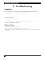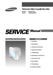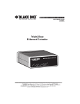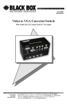
1
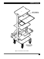
© Copyright 2002. Black Box Corporation. All rights reserved.
1000 Park Drive
•
Lawrence, PA 15055-1018
•
724-746-5500
•
Fax 724-746-0746
JUNE 2002
RM360A-R4
RM361A-R4
RM364A-R4
RM365A-R4
Desktop Serv Rack w/ Sliding Keyboard Shelf & Tray
Tower Serv Rack w/ Sliding Keyboard Shelf & Tray
CUSTOMER
SUPPORT
INFORMATION
Order toll-free in the U.S.: Call 877-877-BBOX (outside U.S. call 724-746-5500)
FREE technical support 24 hours a day, 7 days a week: Call 724-746-5500 or fax 724-746-0746
Mailing address: Black Box Corporation, 1000 Park Drive, Lawrence, PA 15055-1018
Web site: www.blackbox.com • E-mail: [email protected]
FCC/IC RFI STATEMENTS, TRADEMARKS
FEDERAL COMMUNICATIONS COMMISSION AND INDUSTRY CANADA
RADIO-FREQUENCY INTERFERENCE STATEMENTS
This equipment generates, uses, and can radiate radio frequency energy and if not installed and used
properly, that is, in strict accordance with the manufacturer’s instructions, may cause interference to radio
communication. It has been tested and found to comply with the limits for a Class A computing device in
accordance with the specifications in Subpart B of Part 15 of FCC rules, which are designed to provide
reasonable protection against such interference when the equipment is operated in a commercial
environment. Operation of this equipment in a residential area is likely to cause interference, in which
case the user at his own expense will be required to take whatever measures may be necessary to correct
the interference.
Changes or modifications not expressly approved by the party responsible for compliance could void the user’s
authority to operate the equipment.
This digital apparatus does not exceed the Class A limits for radio noise emission from digital apparatus set out in the Radio
Interference Regulation of Industry Canada.
Le présent appareil numérique n’émet pas de bruits radioélectriques dépassant les limites applicables aux appareils numériques
de la classe A prescrites dans le Règlement sur le brouillage radioélectrique publié par Industrie Canada.
TRADEMARKS USED IN THIS MANUAL
UL is a registered trademark of Underwriters Laboratories Incorporated.
Any other trademarks mentioned in this manual are acknowledged to be the property of the trademark owners.
1
DESKTOP AND TOWER SERV RACKS
INSTRUCCIONES DE SEGURIDAD (Normas Oficiales Mexicanas Electrical Safety Statement)
1. Todas las instrucciones de seguridad y operación deberán ser leídas antes de que el aparato eléctrico sea operado.
2. Las instrucciones de seguridad y operación deberán ser guardadas para referencia futura.
3. Todas las advertencias en el aparato eléctrico y en sus instrucciones de operación deben ser respetadas.
4. Todas las instrucciones de operación y uso deben ser seguidas.
5. El aparato eléctrico no deberá ser usado cerca del agua—por ejemplo, cerca de la tina de baño, lavabo, sótano
mojado o cerca de una alberca, etc..
6. El aparato eléctrico debe ser usado únicamente con carritos o pedestales que sean recomendados por el fabricante.
7. El aparato eléctrico debe ser montado a la pared o al techo sólo como sea recomendado por el fabricante.
8. Servicio—El usuario no debe intentar dar servicio al equipo eléctrico más allá a lo descrito en las instrucciones de
operación. Todo otro servicio deberá ser referido a personal de servicio calificado.
9. El aparato eléctrico debe ser situado de tal manera que su posición no interfiera su uso. La colocación del aparato
eléctrico sobre una cama, sofá, alfombra o superficie similar puede bloquea la ventilación, no se debe colocar en
libreros o gabinetes que impidan el flujo de aire por los orificios de ventilación.
10. El equipo eléctrico deber ser situado fuera del alcance de fuentes de calor como radiadores, registros de calor,
estufas u otros aparatos (incluyendo amplificadores) que producen calor.
11. El aparato eléctrico deberá ser connectado a una fuente de poder sólo del tipo descrito en el instructivo de
operación, o como se indique en el aparato.
12. Precaución debe ser tomada de tal manera que la tierra fisica y la polarización del equipo no sea eliminada.
13. Los cables de la fuente de poder deben ser guiados de tal manera que no sean pisados ni pellizcados por objetos
colocados sobre o contra ellos, poniendo particular atención a los contactos y receptáculos donde salen del aparato.
14. El equipo eléctrico debe ser limpiado únicamente de acuerdo a las recomendaciones del fabricante.
15. En caso de existir, una antena externa deberá ser localizada lejos de las lineas de energia.
16. El cable de corriente deberá ser desconectado del cuando el equipo no sea usado por un largo periodo de tiempo.
17. Cuidado debe ser tomado de tal manera que objectos liquidos no sean derramados sobre la cubierta u orificios de
ventilación.
18. Servicio por personal calificado deberá ser provisto cuando:
A: El cable de poder o el contacto ha sido dañado; u
B: Objectos han caído o líquido ha sido derramado dentro del aparato; o
C: El aparato ha sido expuesto a la lluvia; o
D: El aparato parece no operar normalmente o muestra un cambio en su desempeño; o
E: El aparato ha sido tirado o su cubierta ha sido dañada.
2
TABLE OF CONTENTS
Contents
Chapter
Page
1.
Specifications .......................................................................................................................................... 4
1.1 Serv Racks (RM36xA-R4) ............................................................................................................... 4
1.2 Power Strip (Included, North America Only) .............................................................................. 4
2.
Introduction ...........................................................................................................................................
2.1 Available Models .............................................................................................................................
2.2 Description ......................................................................................................................................
2.3 What’s Included ..............................................................................................................................
2.4 Before You Begin Assembling the Serv Rack ................................................................................
3.
Installation .............................................................................................................................................. 8
3.1 Part 1: Attaching the Base Angles to the Vertical Upright Channels .......................................... 8
3.2 Part 2: Attaching the Monitor Shelf .............................................................................................. 9
3.3 Part 3: Doing the Final Tightening ............................................................................................. 10
3.4 Part 4: Securing the Serv Rack ..................................................................................................... 10
3.5 Part 5: Installing the CPU Shelves ............................................................................................... 11
3.6 Part 6: Attaching the Tie-Down Brackets .................................................................................... 12
3.6.1 Desktop Serv Rack (RM360A-R4 and RM361A-R4) .......................................................... 12
3.6.2 Tower Serv Rack (RM364A-R4 and RM365A-R4) ............................................................. 13
3.7 Part 7: Installing the Keyboard Shelf ........................................................................................... 14
3.8 Part 8: Installing the Power Strip (North America Only) .......................................................... 15
4.
Troubleshooting ................................................................................................................................... 16
4.1 Calling Black Box ......................................................................................................................... 16
4.2 Shipping and Packaging ............................................................................................................... 16
5
5
5
6
6
3
DESKTOP AND TOWER SERV RACKS
1. Specifications
1.1 Serv Racks (RM36xA-R4)
Size: 61"H x 23"W x 23"D (155 x 58.4 x 58.4 cm)
Weight: 130 lb. (59.1 kg)
1.2 Power Strip (Included, North America Only)
Compliance: UL®, CSA
Input Rating and Cord: 120 VAC, 60 Hz, 15 amps maximum through a 6-ft. (1.8-m) cord that exits the end of
the enclosure and has a standard NEMA 5-15P plug
Surge Protection:
Circuitry: Single-stage;
Response time: Less than 5 nanoseconds;
UL 1449 clamping voltage and maximum surge resistance: 400 volts (computer grade);
Actual clamping voltage: 350 volts;
Maximum surge current: 13,000 amps;
EMI/RFI noise reduction: 40 dB
Circuit Breaker: 15 amps
User Control: (1) 125-VAC, 15-amp lighted rocker switch
Enclosure: Plastic, mounts with (2) keyhole slots on rear
Output Rating and Connectors: 125 VAC at up to 15 amps on (6) equally spaced NEMA 5-15R outlets
Size: 1.6"H x 2.5"W x 13.25"D (4.1 x 6.4 x 33.7 cm)
Weight: 1.7 lb. (0.8 kg)
4
CHAPTER 2: Introduction
2. Introduction
2.1 Available Models
Currently we offer four Desktop and Tower Serv Rack models:
Product Code
Product Name
RM360A-R4
RM361A-R4
RM364A-R4
RM365A-R4
Beige Desktop Serv Rack with Sliding Keyboard Shelf and Tray
Black Desktop Serv Rack with Sliding Keyboard Shelf and Tray
Beige Tower Serv Rack with Sliding Keyboard Shelf and Tray
Black Tower Serv Rack with Sliding Keyboard Shelf and Tray
We also offer these accessories:
Product Code
Product Name
RM357
RM358
RM359-R2
RM369-R2
Beige CPU Shelf for Desktop and Tower Serv Racks
Black CPU Shelf for Desktop and Tower Serv Racks
Black Sliding Keyboard Shelf with Mouse Tray
Casters
2.2 Description
The Desktop and Tower Serv Racks are designed to organize your computer hardware and eliminate clutter.
One Serv Rack will accommodate up to four desktop or tower CPUs.
These Serv Racks come fully equipped with heavy-duty drilled and tapped steel upright channels, heavy-duty
steel CPU shelves, steel monitor shelf, sliding keyboard shelf, and a 6-outlet surge-protected power strip with a
6-foot (1.8-m) power cord. (The power strip is only included in North America.)
The 23" (58.4-cm) rackmount width allows plenty of room for most standard computers, file servers, towers,
and monitors. The shelves are designed so that the equipment can be operated from a standing position; they
can be positioned at a variety of heights for operator comfort. The extra-deep base assemblies provide superior
stability without having to bolt the unit to the floor. Casters are also available.
The Serv Racks are shipped knocked down and require assembly.
Additional features:
• A switch compartment (2- or 4-port) located under the monitor shelf.
• A drawer-like sliding keyboard shelf with a mouse tray you can position as needed.
• The heavy-duty steel monitor shelf holds up to 75 lb. (34 kg).
• The steel CPU shelves are adjustable and can hold up to 100 lb. (45.4 kg).
5
DESKTOP AND TOWER SERV RACKS
2.3 What’s Included
You should have received the following components with your Serv Rack. Refer to Figure 2-1 on the next page
as you identify where each part goes. (These numbers are also used in the illustrations in Chapter 3.)
Item 1
(2) Vertical upright channels
Item 2
(2) Base angles
Item 3
(1) Monitor shelf with switch compartment
Item 4
(12) 1⁄2" 13 x 1 hex-head bolts
Item 5
(12) 1⁄2" lock washers
Item 6
CPU-shelf packs: (2) for Tower Serv Racks, (4) for Desktop Serv Racks
Item 7
RM360A-R4 and RM361A-R4: (64) 10-32 x 1⁄2" panhead screws;
RM364A-R4 and RM365A-R4: (48) 10-32 x 1⁄2" panhead screws
Item 8
(1) Sliding keyboard shelf with mouse tray
Item 9
(2) Tie-down brackets for tower CPUs, (8) tie-down straps for desktop CPUs
Item 10 North America only: (1) 6-outlet power strip with 6-foot (1.8-m) power cord, mounted
on an adapter bracket
2.4 Before You Begin Assembling the Serv Rack
You will need the following tools in order to assemble the Serv Rack:
• 1⁄2" socket or wrench
• A Phillips screwdriver
• A level or a carpenter’s square
6
CHAPTER 2: Introduction
3
Switch compartment:
4.4"H x 17.75"W x 10"D
(11.2 x 45.1 x 25.4 cm)
8
1
6
9
9
10
1
2
2
Casters are available
separately as product
code RM369-R2
Figure 2-1. Construction of the Serv Rack.
7
DESKTOP AND TOWER SERV RACKS
3. Installation
3.1 Part 1: Attaching the Base Angles to the Vertical Upright Channels
1. Lay the vertical upright channels on their sides. Align the holes in the base with the corresponding holes
in each upright channel (see the illustration below). The long leg of the base should be facing you. Be
sure that the open sides of the upright channels face each other.
2. Install four hex-head bolts and lock washers. Tighten the bolts by hand only at this point.
3. Turn the vertical upright assembly over (rotate 180°) and repeat steps 1 and 2. Tighten by hand only.
1
1
2
2
4
5
Figure 3-1. Attaching the base angles.
8
CHAPTER 3: Installation
3.2 Part 2: Attaching the Monitor Shelf
1. Stand the Serv Rack upright.
2. Align the holes in the monitor shelf with the corresponding holes in the vertical upright channels as
shown in Figure 3-2.
3. If you’re going to install the shelf at the top of the Rack, as shown in Figure 3-2, install four of the included
hex-head bolts and lock washers, then install four of the included panhead screws, tightening everything
by hand only.
4. If you’re going to install the monitor shelf in the Rack but not at the top, use eight panhead screws only.
3
5
4
7
1
1
Figure 3-2. Attaching the monitor shelf at the top of the Serv Rack.
9
DESKTOP AND TOWER SERV RACKS
3.3 Part 3: Doing the Final Tightening
1. Make sure the rack is square by using a level or a carpenter’s square, as shown in Figure 3-3.
2. Tighten all bolts using a socket or wrench.
3
4
7
1
1
4
2
Figure 3-3. Tightening the bolts.
3.4 Part 4: Securing the Serv Rack
1. If your Serv Rack is going to be installed in a permanent location, we recommend bolting it to the floor or
to an equally stabilizing and secure surface using the 4 holes in each of the corners of the base.
2. If the Serv Rack needs to be mobile, order casters (four per set, part number RM369-R2). Mount them
using the holes in each of the corners of the base.
10
CHAPTER 3: Installation
3.5 Part 5: Installing the CPU Shelves
CPU shelves are packed in pairs and are designed to be used with either Desktop or Tower Serv Racks. The
shelves should be mounted back to back. They can also be mounted as single shelves in any EIA spacing.
1. Attach the shelf to the vertical channels by inserting four of the included panhead screws through the
mounting flanges in front of the shelf and tapped holes in the vertical channels, as shown in Figure 3-4.
2. Tighten the screws to secure the shelves.
6
6
7
Figure 3-4. Attaching the Shelves.
11
DESKTOP AND TOWER SERV RACKS
3.6 Part 6: Attaching the Tie-Down Brackets
3.6.1 DESKTOP SERV RACK (RM360A-R4 AND RM361A-R4)
1. Place the CPU in the position you want it on the shelf.
2. Position the tie-down bracket above the CPU with the padded side facing the CPU, as shown in Figure 3-5.
3. Insert four of the included panhead screws through the mounting holes in the rack.
4. Tighten the screws with a Phillips screwdriver.
1
9
6
2
Figure 3-5. Attaching tie-down brackets to a Desktop Serv Rack.
12
CHAPTER 3: Installation
3.6.2 TOWER SERV RACK (RM364A-R4 AND RM365A-R4)
1. Loosen the wing nuts located on both sides of the bracket.
2. Fully extend each bracket’s side member.
3. Loosen the flange nuts located at the rear of the bracket.
4. Fully extend the L-shaped angle brackets to their maximum width.
5. Position the CPU towers where you want them on the shelf.
6. Attach the bracket assembly to the upright channels using eight of the included panhead screws. Repeat
for the other side of the rack.
7. Slide the horizontal member toward the rack until the angle brackets can be positioned at the sides of the
towers.
8. Tighten the wing nuts and repeat for the other side of the rack.
9. Slide the angle brackets against the sides of the towers. Tighten the flange nuts. Repeat for the other side
of the rack.
Angle Bracket
9
Horizontal Header
Side Header
6
1
2
Figure 3-6. Attaching tie-down brackets to a Tower Serv Rack.
13
DESKTOP AND TOWER SERV RACKS
3.7 Part 7: Installing the Keyboard Shelf
1. Select the desired mounting location for the keyboard shelf (either the one included with the Serv Rack or
the RM359-R2 if you’ve ordered it separately). Carefully position the shelf so that the mounting holes in
the shelf’s flanges align with the tapped holes in the vertical channels.
NOTE: Tapped holes are spaced according to EIA-standard universal hole spacing.
2. Attach the keyboard shelf to the vertical channels by inserting four of the included panhead screws
through the mounting flanges in front of the shelf and the tapped holes in the vertical channels.
3. Tighten the screws securely.
4. To use the shelf, simply pull the tray toward you. It will smoothly roll forward on a ball-bearing slide.
5. There are four mounting options for the keyboard shelf’s mouse tray. The tray will be positioned on the
right when you receive the keyboard shelf, as shown in Figure 3-7. If you’d like to move it to one of the
other positions, unscrew the tray. Reposition it and insert the screws you just removed in the pre-drilled
holes. Tighten the screws until the tray is securely in place. The mouse tray slides underneath the the
keyboard shelf when not in use. Make sure to push the tray into this storage position before closing the
shelf.
If you are outside North America, this completes your Serv Rack installation.
Figure 3-7. The keyboard shelf with mouse tray.
14
CHAPTER 3: Installation
3.8 Part 8: Installing the Power Strip (North America Only)
1. If you are in North America, you should have received a power strip with your Serv Rack. This strip has
rackmount brackets attached to it at the factory. Attach the bracketed power strip to the vertical channels
by inserting four of the included panhead screws through the mounting flange in the bracket and the
tapped holes in the vertical channels. We recommend attaching the power strip in the rear of the Serv
Rack, toward the bottom.
2. Tighten the screws.
This completes your Serv Rack installation.
15
DESKTOP AND TOWER SERV RACKS
4. Troubleshooting
4.1 Calling Black Box
If you have any problems with your Serv Rack, contact Black Box Technical Support at 724-746-5500.
Before you do, make a record of the history of the problem. We will be able to provide more efficient and
accurate assistance if you have a complete description, including:
• the nature and duration of the problem;
• when the problem occurs;
• the components involved in the problem;
• any particular application that, when used, appears to create the problem or make it worse; and
• the results of any testing you’ve already done.
4.2 Shipping and Packaging
If you need to transport or ship your Serv Rack:
• Package it carefully. We recommend that you use the original container.
• Before you ship the unit back to Black Box for repair or return, contact us to get a Return Authorization
(RA) number.
16