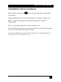
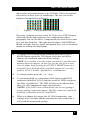
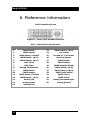
1
March 2005
AC1034A
Video Test Pattern Generator
DVI - VGA - Y Pb Pr
AC1034A
CUSTOMER
SUPPORT
INFORMATION
Order toll-free in the U.S. 24 hours, 7 A.M. Monday to midnight Friday: 877-877-BBOX
FREE technical support, 24 hours a day, 7 days a week: Call 724-746-5500 or fax 724-746-0746
Mail order: Black Box Corporation, 1000 Park Drive, Lawrence, PA 15055-1018
Web site: www.blackbox.com • E-mail: [email protected]
Video Test Pattern Generator
TRADEMARKS USED IN THIS MANUAL
BLACK BOX and its logo
Corporation.
are registered trademarks of Black Box
Apple and Macintosh are registered trademarks of Apple Computer, Inc.
IBM is a registered trademark of International Business Machines
Corporation.
SGI is a registered trademark of Silicon Graphics, Inc.
Sun and Sun Microsystems are registered trademarks of Sun Microsystems,
Inc. in the United States and other countries.
Any other trademarks mentioned in this manual are acknowledged to be
the property of the trademark owners.
1
Model AC1034A
FEDERAL COMMUNICATIONS COMMISSION
AND CANADIAN DEPARTMENT OF COMMUNICATIONS
RADIO FREQUENCY INTERFERENCE STATEMENTS
This equipment generates, uses, and can radiate radio frequency energy
and if not installed and used properly, that is, in strict accordance with
the manufacturer’s instructions, may cause interference to radio
communication. It has been tested and found to comply with the limits
for a Class A computing device in accordance with the specifications in
Subpart B of Part 15 of FCC rules, which are designed to provide
reasonable protection against such interference when the equipment is
operated in a commercial environment. Operation of this equipment in
a residential area is likely to cause interference, in which case the user
at his own expense will be required to take whatever measures may be
necessary to correct the interference.
Changes or modifications not expressly approved by the party
responsible for compliance could void the user’s authority to operate
the equipment.
This digital apparatus does not exceed the Class A limits for radio
noise emission from digital apparatus set out in the Radio Interference
Regulation of the Canadian Department of Communications.
Le présent appareil numérique n’émet pas de bruits radioélectriques
dépassant les limites applicables aux appareils numériques de la classe
A prescrites dans le Règlement sur le brouillage radioélectrique publié
par le ministère des Communications du Canada.
EUROPEAN UNION DECLARATION OF CONFORMITY
This product complies with the requirements of the European EMC
directive 89/336/EEC
2
Video Test Pattern Generator
Normas Oficiales Mexicanas (NOM)
Electrical Safety Statement
INSTRUCCIONES DE SEGURIDAD
1.
2.
3.
4.
5.
6.
7.
8.
9.
10.
11.
12.
13.
14.
15.
16.
17.
18.
A:
B:
C:
D:
Todas las instrucciones de seguridad y operación deberán ser leídas antes de que el
aparato eléctrico sea operado.
Las instrucciones de seguridad y operación deberán ser guardadas para referencia
futura.
Todas las advertencias en el aparato eléctrico y en sus instrucciones de operación
deben ser respetadas.
Todas las instrucciones de operación y uso deben ser seguidas.
El aparato eléctrico no deberá ser usado cerca del agua—por ejemplo, cerca de la
tina de baño, lavabo, sótano mojado o cerca de una alberca, etc.
El aparato eléctrico debe ser usado únicamente con carritos o pedestales que sean
recomendados por el fabricante.
El aparato eléctrico debe ser montado a la pared o al techo sólo como sea
recomendado por el fabricante.
Servicio—El usuario no debe intentar dar servicio al equipo eléctrico más allá a lo
descrito en las instrucciones de operación. Todo otro servicio deberá ser referido a
personal de servicio calificado.
El aparato eléctrico debe ser situado de tal manera que su posición no interfiera su
uso. La colocación del aparato eléctrico sobre una cama, sofá, alfombra o superficie
similar puede bloquea la ventilación, no se debe colocar en libreros o gabinetes que
impidan el flujo de aire por los orificios de ventilación.
El equipo eléctrico deber ser situado fuera del alcance de fuentes de calor como
radiadores, registros de calor, estufas u otros aparatos (incluyendo amplificadores)
que producen calor.
El aparato eléctrico deberá ser connectado a una fuente de poder sólo del tipo
descrito en el instructivo de operación, o como se indique en el aparato.
Precaución debe ser tomada de tal manera que la tierra fisica y la polarización del
equipo no sea eliminada.
Los cables de la fuente de poder deben ser guiados de tal manera que no sean
pisados ni pellizcados por objetos colocados sobre o contra ellos, poniendo
particular atención a los contactos y receptáculos donde salen del aparato.
El equipo eléctrico debe ser limpiado únicamente de acuerdo a las recomendaciones
del fabricante.
En caso de existir, una antena externa deberá ser localizada lejos de las lineas de
energia.
El cable de corriente deberá ser desconectado del cuando el equipo no sea usado por
un largo periodo de tiempo.
Cuidado debe ser tomado de tal manera que objectos liquidos no sean derramados
sobre la cubierta u orificios de ventilación.
Servicio por personal calificado deberá ser provisto cuando:
El cable de poder o el contacto ha sido dañado; u
Objectos han caído o líquido ha sido derramado dentro del aparato; o
El aparato ha sido expuesto a la lluvia; o
El aparato parece no operar normalmente o muestra un cambio en su desempeño; o
E: El aparato ha sido tirado o su cubierta ha sido dañada.
3
Model AC1034A
Contents
1. Introduction ..............................................................................page 5
1.1 General ................................................................................page 5
1.2 Features ...............................................................................page 5
2. Installation .................................................................................page 6
3. Operation ...................................................................................page 7
4. Troubleshooting.......................................................................page 10
4.1 FAQ....................................................................................page 10
4.2 Calling Black Box ..............................................................page 10
4.3 Shipping & Packaging........................................................page 10
5. Specifications...........................................................................page 11
6. Reference Information .............................................................page 12
4
Video Test Pattern Generator
1. Introduction
1.1 General
The Black Box Model AC1034A is a video test pattern generator for
high-resolution display devices.
The unit provides DVI, PC (VGA through SXGA), and HDTV
Component Video (Y,Pb,Pr) outputs. The AC1034A features 28 static
and dynamic video test patterns specially designed for testing,
calibrating, and troubleshooting high end video gear & installations.
In addition to all of standard PC resolutions and refresh rates (up to
SXGA at 85 Hz), it is capable of providing HDTV outputs from 480p
to 1080i both in DVI digital and in YPbPr formats. The OSD indicates
output resolution and refresh rate settings. Among the available 28 test
patterns are: color bar, multi-bust, circle, and crosshatch.
The AC1034A comes in a sturdy metal case and it includes DVI, VGA,
and VGA-to-Component cables to handle most high-end testing and
installation requirements. The AC1034A is ideal to use with LCD,
plasma, CRT monitors, and projectors that are equipped with PC,
Component, or DVI inputs.
1.2 Features
•
3 devices in one. VGA, Component, and DVI video test
pattern Generator
•
Programmable PC output resolutions from 640x480 to
1280x1024 (VGA/SVGA/XGA/SXGA)
•
Programmable HDTV output resolutions from 480p to 1080i
(480i 576i 480p 567p 720p 1080i)
•
28 typical and custom video test patterns (both static and
dynamic)
•
Easy-to-use push-button OSD menu control
•
Includes all cables required
•
Packaged in highly portable EMI shielded enclosure
5
Model AC1034A
2. Installation
1.
Plug the supplied AC adapter to the Power input connector located
on the rear of the unit. Use the supplied adapter or a 100%
equivalent only. There’s a small green LED that turns on when the
unit is powered up.
NOTE
The Video Pattern Generator requires 5 volts regulated DC
Center positive input power, using any other voltage or reverse
polarity will damage the unit and void the warranty.
Figure 1 – Rear Panel & Power Connection
2.
Included in the package are all the cables that you may need: a DVI
cable, a VGA cable, and a HD15 to component Cable (shown
below)
Figure 2 – HD15 to Component Cable
Choose and use the cable required for your application .
6
Video Test Pattern Generator
3. Operation
Ø
The front panel of the unit is pictured below:
Figure 3 - Front panel
Ø
There are two output connectors on the box that are both active
simultaneously. One VGA (HD15) and one DVI.
Ø
The VGA output is dual purpose. It can output standard RGBHV
VESA signals similar to those that are output by most PC’s, as well
as YPbPr component video output. The output mode of the HD15
connector is determined by a small slide switch.
Ø
There’s an indicator LED next to the slide switch that comes on
when the output resolution is one of the standard HDTV
resolutions AND the slide switch is in YPbPr mode.
Ø
To operate the unit you use 3 push-button switches. One button is
used to walk through all the resolutions and refresh rates that are
available (it is labeled OUTPUT MODE). The other 2 buttons are
used to change the video pattern being generated - there are 28
patterns (these buttons are labeled + and - ).
Ø
For quick jump to a known resolution (instead of walking through
them one by one using the MODE switch), pressing two buttons
simultaneously jumps to a given resolution/refresh rate. Pressing
the left two buttons gets you to XGA at 60 Hz (and subsequent
pressing of the MODE button will take you up from there).
Pressing the right two buttons gets you to 480p (a standard HDTV
mode). Please note that in these HDTV modes, the DVI is
outputting the proper signal and if the slide switch is in VGA you
are getting RGBHV output and if in YPbPr you get component
video (with sync on Y) and the LED will light to indicate that the
unit is outputting a proper YPbPr output.
7
Model AC1034A
Ø
Here is a list of output resolutions that the Mode button will walk
you through (there’s an on screen display OSD which indicates the
mode setting):
PC Resolutions
VGA
SVGA
XGA
WXGA
SXGA
640 X 480 @ 50/60/72/75/85 Hz
800 X 600 @ 50/56/60/72/75/85 Hz
1024 X 768 @ 50/60/70/75/85 Hz ---- (Quick Select)
1280 X 768 @ 50/60 Hz
1280 X 1024 @ 50/60 Hz
480P
576P
720P
1080i
720 X 480 @ 50/60 Hz
720 X 576 @ 50/60 Hz
1280 X 720 @ 50/60 Hz
1920 X 1080 @ 50/60 Hz
HDTV Resolutions
---- (Quick Select)
Ø
As mentioned earlier the + and – buttons change the video
output screen among the different patterns that are provided. Most
standard patterns are included such as: Color bars, Color bar and Multiburst on same screen, Grey-scale, Checkerboard, Circle, Crosshatch,
etc. However several unique and interesting pattern are also available.
There are 2 dynamic patterns one which changes the screen smoothly
from black to full white, and another which is a checkerboard that
switches white and black squares about once per second (this pattern
may be useful for viewing compression artifacts in a situation where
video is going to be compressed for lower bandwidth transmission or
processed in some way).
Ø
8
Figure 4 – Some of the test patterns
There are 2 patterns with Red Green and Blue horizontal bars over
white and black background that are great for video distribution
testing especially when long cables (both milti-coaxial, or
Category5/6) are used. The high frequency loss in the long cable
runs will cause the color of the horizontal bars to smear to the right.
Black Box sells high quality video amplifiers and extenders have
provisions for compensating for these losses (usually be means of
Video Test Pattern Generator
dip switches or potentiometers as in AC090A). These two patterns
are perfect for these types of installations. The user can set the
amount of compensation perfectly!
Figure 5 – Video transmission test patterns
The same 2 patterns are also useful for Video-over-UTP Category
cable both for the high-frequency loss compensation (above
paragraph), but also for Skew Compensation for those devices that
give you this flexibility. The right and left edges of the RGB bars
should vertically line-up. Again, this pattern gives you a convenient
means for making this adjustment.
q
Operation Summary
To change the resolution being produced press the OUTPUT
MODE button repeatedly. The output screen has an OSD to
indicate the resolution and refresh rate settings
NOTE: It is possible to set the output resolution to one that your
monitor does not support. In this case you my not get a screen.
You can either keep pressing the OUTPUT MODE button as it
eventually goes through all the available outputs in a circular
fashion, or use 2-button “QuickSelect” combinations.
q
To change pattern press the + or – keys.
q
To get analog high res. component video output at the HD15
connector (instead of VGA), slide the switch to YPbPr and press
the 480p “QuickSelect”. The LED will turn on to indicate that
there is a valid component output signal present.
NOTES: If the LED is not on that means you are not getting a
proper analog component output! The DVI connector outputs all
available resolutions (both PC and HDTV)
q
When you change the output, the AC1034A memorizes your
settings after 8 seconds and the next time the unit is tuned on it
will recall the memorized settings.
9
Model AC1034A
4. Troubleshooting
4.1 FAQ
If your monitor goes blank or says “mode not supported”…
It is possible to set the output resolution to one that your monitor does
not support. In this case you my not get a screen. You can either keep
pressing the OUTPUT MODE button as it eventually goes through all
the available outputs in a circular fashion, or use 2-button
“QuickSelect” combination to jump to a specific output immediately
4.2 Calling Black Box
If you determine that your unit is malfunctioning, do not attempt to
repair the unit. Contact Black Box Tech. Support at 724-746-5500.
Before you do, make a record of the history of the problem. We will be
able to provide more efficient and accurate assistance if you have a
complete description, including:
• The nature and duration of the problem;
• The components involved in the problem—that is, what type of
cable, makes and models of computers and monitors, etc.
• The results of any testing you’ve already done.
4.3 Shipping and Packaging
If you need to transport or ship your Splitter:
• Package it carefully. We recommend that you use the original
container.
• Before you ship the unit back to Black Box for repair or return,
contact us to get a Return Authorization (RA) number.
10
Video Test Pattern Generator
5. Specifications
Compliance
CE; FCC Part 15 Subpart B Class A, IC Class
Standards
PC (RGBHV): VGA, SVGA, XGA, SXGA video.
HDTV (YPbPr): 480P, 576P, 720P, 1080i
DVI: All of the above
Interfaces
Supported
Analog Video: VGA, and YPbPr
Digital Video: DVI –I Single link
Video Level
0.7 volts peak-to-peak, on RGB, 3 v on H & V
1vp-p on Y signal, 0.7 vp-p on Pb&Pr in YPbPr mode
Connectors
HD15 for VGA and YPbPr
29 pin female DVI connector
Temperature
Tolerance
Operating: 32 to 122°F (0 to 50°C);
Storage: –40 to +185°F (–40 to +85°C)
Enclosure
Steel
MTBF
90,000 hours (calculated estimate)
Power
From utility-power (mains) outlet, through included
external power supply. Output Voltage: 5v DC CenterPositive 1.5A, maximum
Size
7" W x 7" D x 1.2" H
Weight
1.3. lb box only; 3 lb shipping
11
Model AC1034A
6. Reference Information
DVI Connector pin-out
Figure 6 – Face of DVI Female connector
N/U = Not Used on this product
Pin
Signal name
Pin
Signal name
1
TMDS Data2–
13
TMDS Data3+ (N/U)
2
TMDS Data2+
14
+5V Power
3
TMDS Data2/4 Shield
15
Ground for +5V Power
4
TMDS Data4– (N/U)
16
Hot Plug Detect
5
TMDS Data4+ (N/U)
17
TMDS Data0–
6
DDC Clock
18
TMDS Data0+
7
DDC Data
19
TMDS Data0/5 Shield
8
Analog vertical sync
20
TMDS Data5– (N/U)
9
TMDS Data1–
21
TMDS Data5+ (N/U)
10
TMDS Data1+
22
TMDS Clock Shield
11
TMDS Data1/3 Shield
23
TMDS Clock+
12
TMDS Data3– (N/U)
24
TMDS Clock–
C1
Analog red
C4
Analog horizontal sync
C2
Analog green
C5
Analog ground
C3
Analog blue
12
© Copyright 2005. Black Box Corporation. All rights reserved.
1000 Park Drive
Lawrence, PA 15055-1018
724-746-5500
Fax 724-746-0746