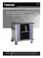
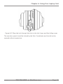
1
Black Box Tech Support: FREE! Live. 24/7. Tech support the way it should be. Great tech support is just 30 seconds away at 724-746-5500 or blackbox.com. About Black Box Black Box Network Services is your source for an extensive range of networking and infrastructure products. You’ll find everything from cabinets and racks and power and surge protection products to media converters and Ethernet switches all supported by free, live 24/7 Tech support available in 30 seconds or less. © Copyright 2012. Black Box Corporation. All rights reserved. LTC20-R2, rev. 1 724-746-5500 | blackbox.com LTC20-R2 LTC26-R2 LTC32-R2 Laptop Carts Mobile, secure, and powered storage for up to 32 laptop computers. BLACK BOX ® The perfect storage solution for institutional laptop computers. Customer Support Information Order toll-free in the U.S.: Call 877-877-BBOX (outside U.S. call 724-746-5500) FREE technical support 24 hours a day, 7 days a week: Call 724-746-5500 or fax 724-746-0746 • Mailing address: Black Box Corporation, 1000 Park Drive, Lawrence, PA 15055-1018 • Web site: www.blackbox.com • E-mail: [email protected] FCC Statement FEDERAL COMMUNICATIONS COMMISSION AND INDUSTRY CANADA RADIO FREQUENCY INTERFERENCE STATEMENTS This equipment generates, uses, and can radiate radio-frequency energy, and if not installed and used properly, that is, in strict accordance with the manufacturer’s instructions, may cause interference to radio communication. It has been tested and found to comply with the limits for a Class A computing device in accordance with the specifications in Subpart B of Part 15 of FCC rules, which are designed to provide reasonable protection against such interference when the equipment is operated in a commercial environment. Operation of this equipment in a residential area is likely to cause interference, in which case the user at his own expense will be required to take whatever measures may be necessary to correct the interference. Changes or modifications not expressly approved by the party responsible for compliance could void the user’s authority to operate the equipment. This digital apparatus does not exceed the Class A limits for radio noise emission from digital apparatus set out in the Radio Interference Regulation of Industry Canada. Le présent appareil numérique n’émet pas de bruits radioélectriques dépassant les limites applicables aux appareils numériques de la classe A prescrites dans le Règlement sur le brouillage radioélectrique publié par Industrie Canada. Normas Oficiales Mexicanas (NOM) Electrical Safety Statement INSTRUCCIONES DE SEGURIDAD 1.Todas las instrucciones de seguridad y operación deberán ser leídas antes de que el aparato eléctrico sea operado. 2.Las instrucciones de seguridad y operación deberán ser guardadas para referencia futura. 3.Todas las advertencias en el aparato eléctrico y en sus instrucciones de operación deben ser respetadas. Page 2 724-746-5500 | blackbox.com LTC20-R2 NOM Statement 4. Todas las instrucciones de operación y uso deben ser seguidas. 5. El aparato eléctrico no deberá ser usado cerca del agua—por ejemplo, cerca de la tina de baño, lavabo, sótano mojado o cerca de una alberca, etc. 6. El aparato eléctrico debe ser usado únicamente con carritos o pedestales que sean recomendados por el fabricante. 7. El aparato eléctrico debe ser montado a la pared o al techo sólo como sea recomendado por el fabricante. 8. Servicio—El usuario no debe intentar dar servicio al equipo eléctrico más allá lo descrito en las instrucciones de operación. Todo otro servicio deberá ser referido a personal de servicio calificado. 9. El aparato eléctrico debe ser situado de tal manera que su posición no interfiera su uso. La colocación del aparato eléctrico sobre una cama, sofá, alfombra o superficie similar puede bloquea la ventilación, no se debe colocar en libreros o gabinetes que impidan el flujo de aire por los orificios de ventilación. 10. El equipo eléctrico deber ser situado fuera del alcance de fuentes de calor como radiadores, registros de calor, estufas u otros aparatos (incluyendo amplificadores) que producen calor. 11. El aparato eléctrico deberá ser connectado a una fuente de poder sólo del tipo descrito en el instructivo de operación, o como se indique en el aparato. 12. Precaución debe ser tomada de tal manera que la tierra fisica y la polarización del equipo no sea eliminada. 13. Los cables de la fuente de poder deben ser guiados de tal manera que no sean pisados ni pellizcados por objetos colocados sobre o contra ellos, poniendo particular atención a los contactos y receptáculos donde salen del aparato. 14. El equipo eléctrico debe ser limpiado únicamente de acuerdo a las recomendaciones del fabricante. 15. En caso de existir, una antena externa deberá ser localizada lejos de las lineas de energia. LTC20-R2 724-746-5500 | blackbox.com Page 3 NOM Statement 16. El cable de corriente deberá ser desconectado del cuando el equipo no sea usado por un largo periodo de tiempo. 17. Cuidado debe ser tomado de tal manera que objectos liquidos no sean derramados sobre la cubierta u orificios de ventilación. 18. Servicio por personal calificado deberá ser provisto cuando: A: El cable de poder o el contacto ha sido dañado; u B: Objectos han caído o líquido ha sido derramado dentro del aparato; o C: El aparato ha sido expuesto a la lluvia; o D: El aparato parece no operar normalmente o muestra un cambio en su desempeño; o E: El aparato ha sido tirado o su cubierta ha sido dañada. Page 4 724-746-5500 | blackbox.com LTC20-R2 Trademarks Used In This Manual Trademarks Used In This Manual Black Box and the Double Diamond logo are registered trademarks of BB Technologies, Inc. The Laptop Cart design is patent pending. Any other trademarks mentioned in this manual are acknowledged to be the property of the trademark owners. LTC20-R2 724-746-5500 | blackbox.com Page 5 Table of Contents Table of Contents 1.0 Specifications .................................................................................................... 7 1.1 Overview ............................................................................................. 7 2.0 What‘s Included ................................................................................................ 8 3.0 Electrical Precautions........................................................................................ 10 3.1 Other Precautions .............................................................................. 10 4.0 Configuration and Setup ................................................................................. 11 4.1 Installing the Handle .......................................................................... 11 4.2 Fastening Power Bricks to the Dividers ............................................... 13 4.3 Inserting Dividers Into the Cart .......................................................... 17 4.4 Routing the Power Cords at the Back of the Laptop Cart ................... 18 5.0 Using the Laptop Cart Timer . .......................................................................... 19 5.1 Before Using the Timer ...................................................................... 19 5.2 Using the Laptop Cart Timer............................................................... 20 6.0 Using Your Laptop Cart.................................................................................... 21 6.1 Charging your Laptop Computers ..................................................... 21 6.2 Moving your Laptop Cart . ................................................................. 21 6.3 Locking your Laptop Cart .................................................................. 22 Page 6 724-746-5500 | blackbox.com LTC20-R2 Chapter 1: Specifications 1.0 Specifications Capacity — Holds up to 20, 26, or 32 laptops Power Strip — All: (1) 2-outlet timer, 120 VAC, 50–60 Hz, 15 amp circuit breaker; LTC20-R2: (2) 10-outlet power strips, 0.75 amps per outlet max.; LTC26-R2: (1) 10-outlet power strip and (1) 16-outlet power strip, 0.75 amps per outlet max.; LTC32-R2: (2) 16-outlet power strips, 0.75 amps per outlet max. Size — Carts: All: 37.8"H x 26.25"D (96 x 66.7 cm); LTC20-R2: 30.25"W (76.8 cm); LTC26-R2: 35.8"W (90.9 cm); LTC32-R2: 41.8"W (106.2 cm); Laptop Compartment: All: 12.75"H x 1.87"W x 17"D (32.4 x 4.7 x 43.2 cm) Weight — LTC20-R2: 154 lb. (70 kg); LTC26-R2: 176 lb. (80 kg); LTC32-R2: 208 lb. (94.5 kg) 1.1 Overview The Laptop Cart (LTC) is designed to store, transport, and charge laptop computers, tablet PCs, ultra mobile PCs, and other similar devices. Units are available with capacities for 20, 26, and 32 separate storage bays. Each unit plugs into a typical 120-volt 15-amp outlet. Please read these operating instructions carefully. They contain important advice concerning the use and safety of your LTC. This Laptop Cart must only be used for its intended purpose in accordance with these operating instructions. LTC20-R2 724-746-5500 | blackbox.com Page 7 Chapter 2: What‘s Included 2.0 What‘s Included • Laptop Cart with 20-, 26-, or 32-laptop capacity; some assembly required • (4) casters, including: (2) locking swivel casters and (2) non-locking fixed casters • (1) 2-outlet timer • Power strips: LTC20-R2: (2) 10-outlet; LTC26-R2: (1) 10-outlet and (1) 16-outlet; LTC32-R2: (2) 16-outlet • Power management dividers: LTC20-R2: (22); LTC26-R2: (28); LTC32-R2: (34) • Handle and power cord wrap • (6) Allen-head bolts and 5/32" wrench (for mounting handle) • (1) This user‘s manual • (2) Keys • Power switch Page 8 724-746-5500 | blackbox.com LTC20-R2 Chapter 2: What‘s Included Pop-up Power Center (optional) Laminate Top Handle and Power Cord Wrap Reinforced Metal Locking Hasp Grommet Power Switch Power Management Divider Ventilation Non-locking Casters Locking Casters Tambour Door Figure 2-1. Front of unit. LTC20-R2 724-746-5500 | blackbox.com Page 9 Chapter 3: Precautions 3.0 Electrical Precautions • The power switch must be in the “OFF” position before plugging the LTC into a wall receptacle. • The LTC must ONLY be connected to a 120-volt AC 15- or 20-amp power supply. • The LTC must only be used by adults or with adult supervision. • Always store the power cord around the cord wraps when transporting the LTC. • Never pull the LTC by the power cord. • Do not plug the LTC in if the switch, receptacle(s), or power cord have been damaged. All electrical components on this product must be repaired by a qualified electrician. • Do not use an extension cord in conjunction with the LTC. • Do not use liquids in or around the LTC environment. • Inadequate repair can create significant hazards to users and is not covered by warranty. • For your safety, it is recommended that a qualified electrician test the circuit you will be plugging the LTC into. The circuit should be checked for ground integrity and appropriate branch circuit protection. • The LTC ground prong must be present for safe operation. If the plug is damaged or if the ground prong has been removed, it should be replaced by a qualified electrician. • The use of the LTC including plugging or unplugging laptops, plugging or unplugging the LTC, operating the control switch, and engaging or releasing the directional and locked casters must be done with adult supervision. 3.1 Other Precautions • The LTC can be very heavy when fully loaded with laptops and should be moved about by persons physically able to do so. • The LTC should only be used for the storage, transport, and charging of laptops, tablet PCs, ultra mobile PCs, and other similar devices while they are not in use. • Plugging other electrical devices into the power strips may overload the system. • Misuse, incorrect operation, or inadequate repair of the LTC will void the warranty. Page 10 724-746-5500 | blackbox.com LTC20-R2 Chapter 4: Configuration and Setup 4.0 Configuration and Setup Retain all packaging materials until it is confirmed that the cart is in full working order. Once the cart is unpacked, lock the lockable casters. Open and inspect the LTC to verify all doors, locks, and casters are working properly. Do not plug the LTC into a wall outlet until all configurations and setup are complete. 4.1 Installing the Handle It is possible to install the handle/cord wrap on either side of the LTC. Black Box recommends that you mount the handle on the side of the cart with the locking swivel casters. NOTE: The casters swivel on one side of the LTC and are fixed on the other. Consider maneuverability options before installing the handle. Step 1: Locate the side of the cart with the locking swivel casters. Handle See "Detail A", next page Swivel Casters Figure 4-1. Handle installation. LTC20-R2 724-746-5500 | blackbox.com Page 11 Chapter 4: Configuration and Setup Step 2. Place the handle so that the holes in the brackets are aligned with the threaded holes in the side panels. 1/4-20 x 5/8" Allen cap screw Figure 4-2. Detail A: handle assembly. Step 3. Using the included Allen wrench, tighten four of the Allen-head screws into the threaded holes. Page 12 724-746-5500 | blackbox.com LTC20-R2 Chapter 4: Configuration and Setup 4.2 Fastening Power Bricks to the Dividers Attach power bricks to the dividers to create separate slots for the laptop computers. Remove a divider to install a laptop power brick to the divider. Step 1. Lay the divider flat on the work surface. Lay a laptop and a power brick on top of the divider, with the computer end of the power wire toward the top of the divider. Plug the power brick into the laptop. Lay the wire across the two holes at the top of the divider. Make sure that there is some slack between the front hole and the plug. Make sure there is slack at these two points Laptop Cord slack Note this point Power Brick Align the back of the laptop with the back of the divider Figure 4-3. How to thread the electrical cable through the dividers. Step 2: Note the point where the power wire meets the rear hole in the divider. Measure back 6" toward the power brick and fold the wire in half to create a loop in the center of the wire. This loop will be used in Step 3, page 14. Unplug the power wire from the laptop and remove the laptop from the divider. Figure 4-4. Loop the electrical cord and push it through the circular hole at the top rear of the divider. LTC20-R2 724-746-5500 | blackbox.com Page 13 Chapter 4: Configuration and Setup Step 3: Insert the loop created in Step 2 through the small rear hole at the top of the divider (Figure 4-4). Then, place the plug end of the wire through the loop (Figure 4-5). Make sure that the loop is on the side of the divider (not on top of it—see Figure 4-6). This will ensure that the divider will slide back into the cart. Then, tighten the loop down to the divider, tightening the knot. Figure 4-5. Insert the plug end of the wire through the loop. Figure 4-6. Make sure the loop is on the side of the divider, not on top of it. Step 4. Run the wire along the top of the divider and repeat the process of creating a loop in the power cord. Place this loop through the small hole at the front of the divider (Figure 4-7). Now place the plug end of the wire through the loop (Figure 4-8). Pull the end of the cable, tightening the loop (Figure 4-9). Figure 4-7. Create a loop from the power cable and feed it through the hole at the top front of the divider. Figure 4-8. Insert the plug end of the wire through the loop. Page 14 724-746-5500 | blackbox.com LTC20-R2 Chapter 4: Configuration and Setup Figure 4-9. Pull the cable taught to secure the loop. Step 5: Wrap the remaining length of power cord around the power brick (see Figure 4-10). Step 6: Wrap the plug wire around the brick. Leave at least 7" of extra cable if the divider will be inserted into the bottom shelf, or at least 21" of extra cable if the divider will be inserted into the top shelf. Figure 4-10. Wrap the remaining electrical cable around the power brick. Leave 7" of extra cable if the divider will be inserted into the bottom shelf, or at least 21" of extra cable if the divider will be inserted into the top shelf. Step 7: Hold the brick and cords in place by strapping them down using a zip tie or a hook-and-loop tie (see Figure 4-11, page 16). LTC20-R2 724-746-5500 | blackbox.com Page 15 Chapter 4: Configuration and Setup Figure 4-11. Strap the brick and cord in place using a zip tie or hook-and-loop tie (not included). Step 8: Install the assembled divider into the cart using the following steps. Figure 4-12. A divider with a power brick properly attached. NOTE: For proper installation, make certain that all power bricks are installed on the same side of every divider. Page 16 724-746-5500 | blackbox.com LTC20-R2 Chapter 4: Configuration and Setup 4.3 Inserting Dividers Into the Cart Step 1: Beginning with the top row, insert a divider into the cart. Figure 4-13. Begin to insert dividers into the top row of the cart. Step 2: Then, from the back of the cart, insert the power brick plugs hanging from the dividers on the left side of the cart into the power receptacles located on the bottom left of the cart. Repeat with the power brick plugs on the right side of the cart into the power receptacles located on the bottom right of the cart. Figure 4-14. Laptop Cart dividers with attached power bricks. Step 3: Plug the power cord from the bottom left receptacles into one of the timer’s receptacles and the power cord from the bottom right receptacles into the timer’s other receptacle. LTC20-R2 724-746-5500 | blackbox.com Page 17 Chapter 4: Configuration and Setup Figure Figure 4-15. Electrical schematic for the back of the Laptop Cart. Note the location of the timer. In the back of the LTC, insert the power cord from the 10- or 16-electrical outlet unit into the LEFT outlet on the timer and plug the other electrical outlet unit into the RIGHT outlet on the timer. Push the timer tabs (located at the edges of the timer dial) inward towards the center of the dial. This will turn one side of the outlets on while turning the other off. 4.4 Routing the Power Cords at the Back of the Laptop Cart Step 1: Plug the laptop outlet strips into the timer unit. Step 2: Feed the cord from the timer through the grommet hole on the side nearest the handle and wrap the cord around the handle itself or around the cord wrap below the handle. Step 3. Plug the timer into a wall outlet. NOTE: The outlet strips are only to be used for charging laptop computers while the devices are not in use (full off). Page 18 724-746-5500 | blackbox.com LTC20-R2 Chapter 5: Using the Laptop Cart Timer 5.0 Using the Laptop Cart Timer 5.1 Before Using the Timer For your safety, it is recommended that a qualified electrician test the circuit into which you will plug the Laptop Cart. The circuit should be checked for ground integrity and appropriate branch circuit protection. Figure 5-1. The Laptop Cart timer. The LTC ground prong must be present for safe operation. If the plug is damaged or if the ground prong has been removed it should be replaced by a qualified electrician. NOTE: The use of the LTC, including plugging in or unplugging the LTC, plugging in or unplugging laptops or other electrical equipment, adjusting the timer settings, or operating the control switch must be done with adult supervision. LTC20-R2 724-746-5500 | blackbox.com Page 19 Chapter 5: Using the Laptop Cart Timer 5.2 Using the Laptop Cart Timer • The timer comes preset from the factory to alternate power between the power strips at 15 minute intervals. To change time settings, first unplug the timer from the wall. Using a flat blade screwdriver, turn the settings dial to a new number: 0 = 15 mins 4 = 75 mins 1 = 30 mins 5 = 90 mins 2 = 45 mins 6 = 105 mins 3 = 60 mins 7 = 1200 mins • Both power strips cannot charge simultaneously. • Plug the cart power cord into an approved outlet and flip the red switch located on the left side panel of the cart to begin charging. • To turn off the power, turn off the red switch and unplug the cart from the wall outlet. Page 20 724-746-5500 | blackbox.com LTC20-R2 Chapter 6: Using Your Laptop Cart 6.0 Using your Laptop Cart 6.1 Charging your Laptop Computers • After the laptop computers have been loaded into the LTC as described previously, plug the power cord of the LTC into a suitable receptacle. • Locate the external power switch on the side panel of the LTC and push the switch to the ON position. • The charging indicator lights on the laptops may be visible through the locked tambour doors to verify charging. 6.2 Moving your Laptop Cart • Turn the external power switch to the off position. • Remove the LTC plug from the wall receptacle and wrap the cord around the cord wrap or handle. • Close and secure tambour doors. • Your LTC comes equipped with two fixed casters and two locking swivel casters. Unlock the casters prior to moving the LTC to a new location. • When you reach your desired destination, lock the casters to prevent the cart from moving and plug the LTC into a wall receptacle. LTC20-R2 724-746-5500 | blackbox.com Page 21 Chapter 6: Using Your Laptop Cart 6.3 Locking your Laptop Cart Close the tambour doors. Make sure the sliding lock cover is below the lock hasps, and then slide the doors together. Figure 6-1. Close the tambour doors and align the lock hasps. With the doors together, slide the lock cover up over the hasps. Place the lock through the slots in the lock hasps and the sliding cover. Figure 6-2. Slide the lock cover up over the hasps. Page 22 724-746-5500 | blackbox.com LTC20-R2 Chapter 6: Using Your Laptop Cart Figure 6-3. Place the lock through the slots in the lock hasps and the sliding cover. The rear door panel should be locked by the Tech Coordinator and should not be opened without supervision. LTC20-R2 724-746-5500 | blackbox.com Page 23