1
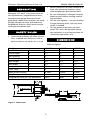
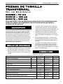
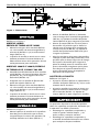
operating manual & parts list
30303B, 30601B & 30801B
E
N
G
L
I
S
H
3″, 6″ & 8″
CROSS VISE
E
S
P
A
Ñ
O
L
Read carefully and follow all safety rules and operating instructions
before first use of this product.
28865.00 - 0711
Palmgren Operating Manual & Parts List
30303B, 30601B & 30801B
• Bolt or clamp vise to work surface in at
least two mounting locations using
mounting flanges provided on base.
• Be sure workpiece is clamped securely
between jaws before starting machining operation.
• Do not over tighten—vise can develop
a large clamping force. Use only force
which is needed.
• Do not pound or hammer on workpiece. This vise is designed to clamp
the workpiece in a desired position for
machining operations only.
DESCRIPTION
Palmgren 3”, 6” and 8” Cross Vises travel on
two separate axes, longitudinal and cross ,
to permit accurate positioning of workpiece. Body, saddle, base and jaws are made
of high strength cast iron. Vise leadscrew,
longitudinal and cross feed screws are precision ground carbon steel.
SAFETY RULES
• Understand and obey all safety instructions supplied with drill press, mill, or
other machines on which vise is used.
DIMENSIONS
Refer to Figure 1.
Stock No.
Jaw Width
A
Throat Depth
B
Jaw Opening
C
Overall Height
H
Base Length
L
Base Width
W
Longitudinal Travel
Cross Travel
Value of One Division
Cross Travel per One Revolution
Longitudinal Travel per One Revolution
30303B
3“
11/8“
3“
55/8“
81/4“
41/2“
5”
5”
0.1mm
3mm
3mm
30601B
6“
2“
6“
71/4“
121/4“
71/2“
8”
8”
0.1mm
4mm
4mm
30801B
8”
2“
8“
71/4“
121/4“
71/2“
8”
8”
0.1mm
4mm
4mm
W
L
A
C
B
H
Figure 1 - Dimensions
2
Palmgren Operating Manual & Parts List
30303B, 30601B & 30801B
• Move vise body (Ref. No. 16) to desired
position by rotating crossfeed crank
handle (Ref. No. 12). Tighten center set
screw (Ref. No. 6) to secure position.
• Open jaws of vise. Place workpiece
between jaws in desired position.
Rotate vise handle to secure workpiece
between vise jaws. Be sure workpiece is
secure in vise before starting machining operation.
ASSEMBLY
Refer to Figure 2.
MODEL 30303B, 3″ VISE
• Mount crank handles (Ref. No. 12) to
longitudinal and cross feed screws (Ref.
Nos. 8 and 9) using acorn nuts (Ref. No.
13).
• This vise is shipped with a protective
coating. This coating should be
removed before operation. Remove
protective coating with penetrating oil.
GIB ADJUSTMENT
• Adjust gibs (Ref. No. 4) by tightening
the set screws (Ref. Nos. 6 and 23) at
each end of the gibs.
• Adjust the screws until a slight drag is
felt when rotating the crank handles
(Ref. No. 12). Tighten nuts (Ref. No. 5) to
secure screws.
MODELS 30601B AND 30801B,
6″ AND 8″ VISES
• Thread movable jaw leadscrew (Ref.
No. 14) through end of body (Ref. No.
16) and into hole in movable jaw (Ref.
No. 18).
• Secure with dog point set screw (Ref.
No. 19)
• Mount crank handles (Ref. No. 12) to
logitudinal and cross feed screws (Ref.
Nos. 8 and 9) using acorn nuts (Ref. No.
13).
• This vise is shipped with a protective
coating. This coating should be
removed before operation. Remove
protective coating with penetrating oil.
MAINTENANCE
Particles of metal or wood can damage
machined surfaces, causing difficult or
inaccurate operation.
• The vise is shipped with a protective
coating. This coating should be
removed before operation. Use penetrating oil to remove protective coating.
• Keep machined surfaces and all moving parts clean and free of dirt, chips
and foreign materials.
• Keep machined surfaces and leadscrews lubricated with medium weight
machine oil.
OPERATION
Refer to Figure 2.
• Mount vise to work surface in desired
location by securing at least two
mounting flanges located on base
(Ref. No. 1).
• Move saddle (Ref. No. 3) by rotating longitudinal crank handle (Ref. No. 12).
Tighten center set screw (Ref. No. 6) to
secure position.
3
Palmgren Operating Manual & Parts List
30303B, 30601B & 30801B
21
19
20
13
18
17
25
17
24 22
14
12
25 13
16
4
5
23
24
15
7
11
6
12
8
11
3
10
9
23
2
7
4
1
5
6
Figure 2 - Replacement Parts Illustration for 3“ , 6“ and 8“ Cross Vise
4
Palmgren Operating Manual & Parts List
30303B, 30601B & 30801B
REPLACEMENT PARTS LIST FOR CROSS VISES
Ref.
No. Description
Part Number for:
3″ 30303B 6″ 30601B 8″ 30801B
1
2
3
4
5
6
6
7
8
9
10
11
11
12
13
14
15
16
17
17
17
18
19
20
21
22
23
23
24
24
25
Δ
28866.00
28867.00
28868.00
28869.00
*
*
–
28870.00
28871.00
28872.00
28873.00
*
–
28874.00
28875.00
28876.00
28877.00
28878.00
*
–
–
28879.00
28880.00
28881.00
28882.00
28883.00
*
–
*
–
–
28865.00
Base
Nut
Saddle
Gib
6-1.0mm Hex Nut
6-1.0 x 16mm Set Screw
6-1.0 x 20mm Set Screw
1/8″ Ball
Longitudinal Feed Screw
Cross Feed Screw
Retaining Plate
6-1.0 x 16mm Socket Head Bolt
8-1.25 x 25mm Socket Head Bolt
Crank Handle Assmebly
6-1.0mm Acorn Nut
Leadscrew with Handle
Guide Rod
Body
6-1.0 x 10mm Socket Head Bolt
8-1.25 x 14mm Socket Head Bolt
8-1.25 x 25mm Socket Head Bolt
Movable Jaw
6-1.0 x 12mm Dog Point Set Screw
Jaw Plate
Grooved Jaw Plate
Retaining Plate
6-1.0 x 16mm Set Screw
6-1.0 x 25mm Set Screw
6mm Lock Washer
8mm Lock Washer
6mm Flat Washer
Operator’s Manual
Δ Not shown.
* Standard hardware item available locally.
5
28884.00
28885.00
28886.00
28887.00
*
–
*
28888.00
28889.00
28890.00
28891.00
–
*
28892.00
28893.00
28894.00
28895.00
28896.00
–
*
–
28914.00
28897.00
28898.00
28899.00
28900.00
–
*
–
*
*
28865.00
28884.00
28885.00
28886.00
28887.00
*
–
*
28888.00
28889.00
28890.00
28891.00
–
*
28892.00
28893.00
28901.00
28902.00
28903.00
–
–
*
28904.00
28897.00
28905.00
28906.00
28900.00
–
*
–
*
*
28865.00
Qty.
1
1
1
2
6
4
4
2
1
1
1
4
4
2
2
1
1
1
4
4
4
1
1
1
1
1
2
2
4
4
2
1
Manual de Operación y Lista de Partes de Palmgren
30303B, 30601B y 30801B
PRENSA DE TORNILLO
TRANSVERSAL
No. de Existencia
30303B – 76 mm
30601B – 152 mm
30801B – 203 mm
Antes de utilizar este producto por primera vez, lea cuidadosamente
todas las normas de seguridad y las instrucciones de operación y
cumpla con las mismas.
•
DESCRIPCION
Las Prensas de Tornillo Transversales de 76, 152 y
203 mm Palmgren se mueven sobre dos ejes
separados, uno longitudinal y otro transversal,
para permitir la colocación precisa de la pieza
de trabajo. El cuerpo, el caballete, la base y las
mordazas están fabricados de hierro fundido de
alta resistencia. El tornillo de entrada de la prensa de tornillo, así como los tornillos de avance
longitudinal y transversal, son de acero al carbono esmerilados a precisión.
•
•
•
REGLAS DE SEGURIDAD
•
Entienda y obedezca todas las instrucciones
de seguridad que se proporcionan con la
prensa taladradora, la fresadora o con otras
máquinas en las cuales se usa la prensa de
tornillo.
No. de Existencia
Ancho de la Mordaza
Profundidad de la Garganta
Abertura de la Mordaza
Altura Total
Longitud de la Base
Ancho de la Base
Recorrido Longitudinal
Recorrido Transversal
Valor de una División
Recorrido Transversal por Revolución
Recorrido Longitudinal por Revolución
Aperne o agarre la prensa de tornillo a la
superficie de trabajo en por lo menos dos
lugares de montaje, usando las pestañas de
montaje que se proporcionan en la base.
Asegúrese que la pieza de trabajo esté
firmemente agarrada entre las mordazas
antes de empezar la operación de maquinado.
No la apriete demasiado — la prensa de
tornillo puede desarrollar una gran fuerza
de agarre. Use solamente la fuerza que se
necesita.
No golpee ni martille la pieza de trabajo.
Esta prensa de tornillo ha sido diseñada
para agarrar la pieza de trabajo en la posición que se desea solamente para las operaciones de maquinado.
DIMENSIONES
Refiérase a la Figura 1.
A
B
C
H
L
W
6
30303B
76 mm
29 mm
81 mm
143 mm
210 mm
114 mm
127 mm
127 mm
0,1 mm
3,0 mm
3,0 mm
30601B
152 mm
50 mm
152 mm
188 mm
312 mm
190 mm
203 mm
203 mm
0,1 mm
4,0 mm
4,0 mm
30801B
203 mm
50 mm
203 mm
188 mm
312 mm
190 mm
203 mm
203 mm
0,1 mm
4,0 mm
4,0 mm
Manual de Operación y Lista de Partes de Palmgren
30303B, 30601B y 30801B
W
L
A
C
B
H
Figura 1 - Dimensiones
•
MONTAJE
Refiérase a la Figura 2.
•
MODELO 30303B
PRENSA DE TORNILLO DE 76 MM
•
•
Monte los mangos de la manivela (Ref. No.
12) a los tornillos de avance longitudinal y
transversal (Ref. Nos. 8 y 9) usando tuercas
ciegas (Ref. No. 13).
La prensa de tornillo se envía con un revestimiento protector. Este revestimiento se
debe remover antes de la operación. Use un
aceite penetrante para removerlo.
•
MODELOS 30601B Y 30801B, PRENSAS
DE TORNILLO DE 152 MM Y 203 MM
•
•
•
•
Atornille el tornillo de entrada de la mordaza
móvil (Ref. No. 14) hasta el extremo del cuerpo (Ref. No. 16) y en el agujero de la mordaza móvil (Ref. No. 18).
Asegúrelo con un tornillo de fijación del
punto de sujeción (Ref. No. 19).
Monte los mangos de la manivela (Ref. No.
12) a los tornillos de avance longitudinal y
transversal (Ref. Nos. 8 y 9) usando tuercas
ciegas (Ref. No. 13).
La prensa de tornillo se envía con un revestimiento protector. Este revestimiento se
debe remover antes de la operación. Use un
aceite penetrante para removerlo.
Mueva el caballete (Ref. No. 3) haciendo
rotar el mango de la manivela longitudinal
(Ref. No. 12). Apriete el tornillo de fijación
central (Ref. No. 6) para asegurar la posición.
Mueva el cuerpo (Ref. No. 16) de la prensa
de tornillo a la posición que se desea haciendo rotar el mango de la manivela de
avance transversal (Ref. No. 12). Apriete el
tornillo de fijación central (Ref. No. 6) para
asegurar la posición.
Abra las mordazas de la prensa de tornillo y
coloque la pieza de trabajo entre ellas, en la
posición que se desea. Haga rotar el mango
de la prensa de tornillo para asegurar la
pieza de trabajo entre las mordazas de la
prensa de tornillo. Asegúrese que la pieza
de trabajo esté sujeta firmemente en la
prensa de tornillo antes de empezar la
operación de maquinado.
AJUSTE DE LA CHAVETA
Refiérase a la Figura 2.
• Ajuste las chavetas (Ref. No. 4) apretando los
tornillos de fijación (Ref. Nos. 6 y 23) en cada
extremo de las chavetas.
• Ajuste los tornillos hasta que se sienta una
ligera resistencia al hacer rotar los mangos
de la manivela (Ref. No. 12). Apriete las
tuercas (Ref. No. 5) para asegurar los tornillos.
MANTENIMIENTO
Las partículas de metal o de madera pueden
dañar las superficies maquinadas, haciendo que
la operación sea difícil o incorrecta.
• Mantenga las superficies maquinadas y
todas las partes móviles limpias y sin
polvo, astillas y materias extrañas.
• Mantenga las superficies maquinadas y
el tornillo de entrada lubricados con aceite
para máquinas de peso mediano.
OPERACION
Refiérase a la Figura 2.
• Monte la prensa de tornillo en la superficie
de trabajo, en la ubicación que se desea,
asegurando por lo menos dos pestañas de
montaje ubicadas en la base (Ref. No. 1).
7
Palmgren Operating Manual & Parts List
30303B, 30601B & 30801B
WARRANTY
Palmgren warrants their products to be free of deficiency in material or workmanship.
The duration of this warranty is expressively limited to one year parts and labor unless
otherwise noted beginning from the date of delivery to the original user. The following
Palmgren products carry the following warranties on parts with a 1 year warranty on
labor:
•
•
•
•
•
•
•
USA Machine vises – Lifetime
Imported Machine vises – 2 years
Bench vises – 2 years
Positioning tables – 2 years
Bench grinders & buffers – 3 years
Tapping machines – 2 years
Drilling machines – 2 years
• Finishing machines – 2 years
• Band saws – 2 years
• Work stands – 2 years
The obligation of Palmgren is limited solely to the repair or replacement, at our option,
at its factory or authorized repair agent of any part that should prove deficient. The
warranty does not cover expendable and/or wear parts (i.e. v-belts, coated abrasives),
damage to tools arising from alteration, abuse or use other than their intended purpose,
packing and freight. Purchaser must lubricate and maintain the product under normal
operating conditions at all times. Proper use and care instructions are provided in the
operator’s manual. Failure to follow these instructions will void the warranty.
This warranty is the purchaser’s exclusive remedy against Palmgren for any deficiency in
its products. Under no circumstances is Palmgren liable for any direct, indirect, incidental, special or consequential damages including lost profits in any way related to the use
or inability to use our products. This warranty gives you specific legal rights which may
vary from state to state.
SERVICE & REPAIR
1. If a Palmgren product requires a repair or warranty service DO NOT return the
product to the place of purchase.
2. All warranty related work must be evaluated and approved by Palmgren.
3. Prior to returning any item the user must obtain factory approval and a valid RGA
number.
4. For instructions and RGA number call toll free (800) 621-6145.