1
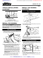
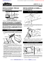
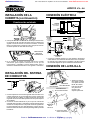
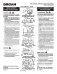
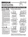
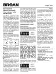
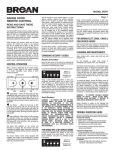
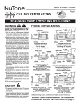
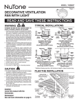
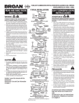
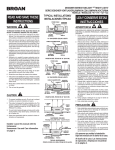
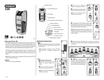
::bathroomsource.com
www.bathroomsource.com
Call 1-800-667-8721 anywhere in the US and Canada -
MODELS 676 • 684
®
Page 1
CEILING VENTILATORS
READ AND SAVE THESE INSTRUCTIONS
TYPICAL INSTALLATIONS
WARNING
TO REDUCE THE RISK OF FIRE, ELECTRIC
SHOCK, OR INJURY TO PERSONS, OBSERVE THE FOLLOWING:
1. Use this unit only in the manner intended by
the manufacturer. If you have questions, contact the manufacturer at the address or telephone number listed in the warranty.
2. Before servicing or cleaning unit, switch
power off at service panel and lock the service disconnecting means to prevent power
from being switched on accidentally. When
the service disconnecting means cannot be
locked, securely fasten a prominent warning device, such as a tag, to the service
panel.
3. Installation work and electrical wiring must
be done by a qualified person(s) in accordance with all applicable codes and standards, including fire-rated construction
codes and standards.
4. Sufficient air is needed for proper combustion and exhausting of gases through the
flue (chimney) of fuel burning equipment to
prevent backdrafting. Follow the heating
equipment manufacturer’s guideline and
safety standards such as those published
by the National Fire Protection Association
(NFPA), and the American Society for Heating, Refrigeration and Air Conditioning Engineers (ASHRAE), and the local code authorities.
5. When cutting or drilling into wall or ceiling,
do not damage electrical wiring and other
hidden utilities.
6. Ducted fans must always be vented to the
outdoors.
7. If this unit is to be installed over a tub or
shower, it must be marked as appropriate
for the application and be connected to a
GFCI (Ground Fault Circuit Interrupter) - protected branch circuit.
8. Never place a switch where it can be
reached from a tub or shower.
9. This unit must be grounded.
CAUTION
!
1. For general ventilating use only. Do not use
to exhaust hazardous or explosive materials and vapors.
2. To avoid motor bearing damage and noisy
and/or unbalanced impellers, keep drywall
spray, construction dust, etc. off power unit.
3. Please read specification label on product
for further information and requirements.
Broan at
POWER CABLE
4" ROUND
DUCT
POWER CABLE
MOUNTING TABS
MOUNTING TABS
CEILING
JOIST
HOUSING
HOUSING
CEILING
MATERIAL
CEILING
MATERIAL
GRILLE
HOUSING MOUNTED
DIRECTLY TO JOIST
2x6 (or larger)
Discharge parallel to joists.
POWER CABLE
MOUNTING
TABS
*
HOUSING MOUNTED
TO ADDITIONAL FRAMING
Discharge 900 to joists.
4" ROUND
DUCT
POWER CABLE
ADDITIONAL
FRAMING
*
2x4
CEILING
JOIST or
TRUSS
ADDITIONAL
FRAMING * CEILING
JOIST
GRILLE
MOUNTING TABS
2x4
CEILING
JOIST or
TRUSS
HOUSING
HOUSING
CEILING
MATERIAL
2x4
CEILING
JOIST or
TRUSS
GRILLE
HOUSING MOUNTED
TO 2x4 TRUSS
Requires additional framing
for mounting tabs.
Discharge parallel to joists.
CEILING
MATERIAL
ADDITIONAL
FRAMING
2x4
* CEILING
GRILLE
JOIST or
TRUSS
HOUSING MOUNTED TO 2x4 TRUSS
Requires additional framing
for mounting tabs.
Discharge 900 to joists.
4" ROUND
DUCT
POWER CABLE
ADDITIONAL
POWER CABLE
FRAMING
MOUNTING
TABS
*
MOUNTING TABS
HOUSING
HOUSING
"I "
JOIST
CEILING
MATERIAL
GRILLE
"I "
JOIST
"I"
JOIST
HOUSING MOUNTED TO “I” JOIST
Requires additional framing
for mounting tabs.
Discharge parallel to joists.
CEILING GRILLE
MATERIAL
ADDITIONAL
FRAMING
*
"I "
JOIST
HOUSING MOUNTED TO “I” JOIST
Requires additional framing
for mounting tabs.
Discharge 900 to joists.
* Additional framing must be a 2x6 (minimum height), at least 9-inches long.
Installer: Leave this manual with the homeowner.
Homeowner: Use and Care information on page 4.
::bathroomsource.com is a division of kitchen::accessories
U
N
L
I
M
I
T
E
D
::bathroomsource.com
Call 1-800-667-8721 anywhere in the US and Canada -
www.bathroomsource.com
MODELS 676 • 684
®
Page 2
TYPICAL INSTALLATIONS
(continued)
INSTALL THE HOUSING
(continued)
New Construction
4" ROUND
DUCT
POWER
CABLE
MOUNTING
TAB
HOUSING
SUSPENDED
CEILING MATERIAL
GRILLE
SUSPENDED CEILINGS
Housing hung with wires - 3-point mount.
INSTALL THE HOUSING
- PLEASE NOTE THE FOLLOWING INSTALLATION ILLUSTRATIONS SHOW 2 X 6
JOISTS. IF YOU HAVE A TRUSS OR “I”-JOIST INSTALLATION,
MOUNT THE VENTILATOR TO THE ADDITIONAL FRAMING IN THE
SAME MANNER. (Additional framing must be a 2x6 (minimum height),
at least 9-inches long.)
3. Set housing aside and drive nails partially into joist at the
top of both keyhole marks.
New Construction
1. Choose the location for your fan in the ceiling. For best
possible performance, use the shortest possible duct run
and a minimum number of elbows.
HOLES
4. Hang housing from nails and pound nails tight. To ensure
a noise-free mount, pound another nail through the top
hole of each mounting tab.
TAB
Existing Construction
1-1/4
1
5/8
BOTTOM EDGE OF JOIST
2. Position mounting brackets against joist so that bottom
edge of housing will be flush with finished ceiling.
Additional positioning feature for 5/8”, 1”, &
1-1/4” thick ceiling material:
Holes in corners of housing are labeled with
various ceiling material thicknesses. Position
housing so bottom edge of joist is visible through
a matched set of holes. The housing is now in the
proper position for that ceiling material thickness.
Additional positioning feature for 1/2” thick
ceiling material:
Bend two tabs, on side of housing, 900 outward. Lift
housing until tabs contact underside of joist.
Mark the keyhole slot on both mounting brackets.
Broan at
1. Choose the location for your fan in the ceiling. For best
possible performance, use the shortest possible duct run
and a minimum number of elbows.
2. In attic, position mounting brackets against joist. Trace
outline of housing on ceiling material.
3. Set housing aside and cut ceiling opening slightly larger
than marked.
::bathroomsource.com is a division of kitchen::accessories
U
N
L
I
M
I
T
E
D
::bathroomsource.com
Call 1-800-667-8721 anywhere in the US and Canada -
www.bathroomsource.com
MODELS 676 • 684
®
Page 3
INSTALL THE HOUSING
(continued)
CONNECT THE WIRING
SCHEMATIC WIRING DIAGRAM
BLK
Existing Construction
BLK
ON / OFF
SWITCH
M
WHT
BLK
WHT
LINE WHT
IN
GRD
GRD
UNIT
SWITCH BOX
BLACK
WHITE
ON / OFF SWITCH
(purchase separately)
SWITCH BOX
4. Place housing in opening so that its bottom edge is flush
with finished ceiling. Nail to joist through keyhole on both
sides. To ensure a noise-free installation, drive another
nail through the top hole of each mounting bracket.
ADDITIONAL
MOUNTING
HOLES
5. Additional mounting holes are provided for installations
where access from above is inconvenient or not possible.
Nail or screw housing directly to joists or framing.
RECEPTACLE
GROUND
(bare)
WIRING
PLATE
120 VAC
LINE IN
1. Wire unit following diagram above. Run electrical cable
as direct as possible to unit. Do not allow cable to touch
sides or top of unit after installation is complete.
ATTACH THE GRILLE
INSTALL THE DUCTWORK
FLUSH
1. Squeeze grille
springs together and
SPRING insert springs into
OPTIONAL TABS
TABS
slots in motor plate.
NOTE: If desired,
SLOT IN
rotate grille 90o and
MOTOR PLATE
move springs to
optional tabs.
1. Snap the damper/duct connector onto housing. Make sure
that tabs on the connector lock into slots in housing. Top
of damper/duct connector should be flush with top of housing.
2. Connect 4” round duct to damper/duct connector and extend duct to outside through a roof or wall cap. Check
damper to make sure that it opens freely. Tape all duct
connections to make them secure and air tight.
GRILLE
SPRING
2. Push grille up
against ceiling.
Broan at
::bathroomsource.com is a division of kitchen::accessories
U
N
L
I
M
I
T
E
D
::bathroomsource.com
Call 1-800-667-8721 anywhere in the US and Canada -
www.bathroomsource.com
MODELS 676 • 684
®
Page 4
USE AND CARE
USE AND CARE
WARNING: DISCONNECT ELECTRICAL POWER SUPPLY AND
LOCK OUT SERVICE PANEL BEFORE CLEANING OR SERVICING THIS UNIT.
CLEANING
TO CLEAN GRILLE:
CAUTION: Plastic parts can be cleaned with mild, soapy water
(use a mild detergent, such as dishwashing liquid) and dried
with a soft cloth. Do not use abrasive cloth, steel wool pads, or
scouring powders.
MOTOR LUBRICATION
The motor is permanently lubricated. Do not oil or disassemble
motor.
TO CLEAN FAN ASSEMBLY:
Unplug fan assembly. To remove motor plate: Find the single tab on
the motor plate (located next to the receptacle). Push up near motor
plate tab while pushing out on side of housing. Or insert a straightblade screwdriver into slot in housing (next to tab) and twist
screwdriver. Gently vacuum fan, motor and interior of housing.
METAL AND ELECTRICAL PARTS SHOULD NEVER BE IMMERSED IN WATER.
9
SERVICE PARTS
12
KEY
1
2
3
4
5
*
PART NO.
97013576
97014926
99080517
99080518
99020276
99260425
97015157
*
97015159
6
7
*
99270982
98009611
97015170
8
9
10
11
12
97014922
97003932
98008868
99150575
99150471
DESCRIPTION
Grille
Motor Plate
Motor (676)
Motor (684)
Impeller
Motor Nut (2 req.)
Blower Assembly (676)
(includes Key Nos. 2 thru 5)
Blower Assembly (684)
(includes Key Nos. 2 thru 5)
Receptacle
Wire Panel
Wire Panel Assembly
(includes Key Nos. 6 & 7)
Housing
Damper/Duct Connector
Wiring Plate
Screw, #8-18 x .375
Ground Screw
* Not shown assembled.
Order replacement parts by “PART NO.” - not by “KEY
NO.”
10
11
7
6
2
1
8
4
3
5
WARRANTY
BROAN-NUTONE ONE YEAR LIMITED WARRANTY
Broan-NuTone warrants to the original consumer purchaser of its products that such products will be free from defects in materials or workmanship for a period of one year from
the date of original purchase. THERE ARE NO OTHER WARRANTIES, EXPRESS OR IMPLIED, INCLUDING, BUT NOT LIMITED TO, IMPLIED WARRANTIES OF MERCHANTABILITY
OR FITNESS FOR A PARTICULAR PURPOSE.
During this one-year period, Broan-NuTone will, at its option, repair or replace, without charge, any product or part which is found to be defective under normal use and service.
THIS WARRANTY DOES NOT EXTEND TO FLUORESCENT LAMP STARTERS AND TUBES. This warranty does not cover (a) normal maintenance and service or (b) any products
or parts which have been subject to misuse, negligence, accident, improper maintenance or repair (other than by Broan-NuTone), faulty installation or installation contrary to
recommended installation instructions.
The duration of any implied warranty is limited to the one-year period as specified for the express warranty. Some states do not allow limitation on how long an implied warranty
lasts, so the above limitation may not apply to you.
BROAN-NUTONE’S OBLIGATION TO REPAIR OR REPLACE, AT BROAN-NUTONE’S OPTION, SHALL BE THE PURCHASER’S SOLE AND EXCLUSIVE REMEDY UNDER THIS
WARRANTY. BROAN-NUTONE SHALL NOT BE LIABLE FOR INCIDENTAL, CONSEQUENTIAL OR SPECIAL DAMAGES ARISING OUT OF OR IN CONNECTION WITH PRODUCT
USE OR PERFORMANCE. Some states do not allow the exclusion or limitation of incidental or consequential damages, so the above limitation or exclusion may not apply to you.
This warranty gives you specific legal rights, and you may also have other rights, which vary from state to state. This warranty supersedes all prior warranties.
To qualify for warranty service, you must (a) notify Broan-NuTone at the address stated below or telephone: 1-800-637-1453, (b) give the model number and part identification and
(c) describe the nature of any defect in the product or part. At the time of requesting warranty service, you must present evidence of the original purchase date.
99042889B
Broan at
::bathroomsource.com is a division of kitchen::accessories
U
N
L
I
M
I
T
E
D
::bathroomsource.com
Call 1-800-667-8721 anywhere in the US and Canada -
www.bathroomsource.com
MODELOS
MODELS 676 • 684
®
Página
Page 5
VENTILADORES DE CIELO RASO
LEA Y CONSERVE ESTAS INSTRUCCIONES
ADVERTENCIA
INSTALACIONES TÍPICAS
PARA REDUCIR EL RIESGO DE INCENDIO,
DESCARGA
ELÉCTRICA
O
LESIONES
PERSONALES, OBSERVE LO SIGUIENTE:
1. Utilice esta unidad solamente de acuerdo con las
instrucciones del fabricante. Si tiene preguntas
comuníquese con el fabricante a la dirección o al número
telefónico que se indica en la garantía.
2. Antes de dar servicio o limpiar la unidad, interrumpa el
suministro de energía en el panel de servicio y bloquee los
dispositivos de desconexión para evitar la reinstalación
accidental de la energía. Cuando no se puedan bloquear
los dispositivos de desconexión, fije seguramente en el
panel de servicio un medio de advertencia que sea visible,
como por ejemplo una etiqueta.
3. Una persona o personas calificadas deben realizar el
trabajo de instalación y el cableado eléctrico, de acuerdo
con todos los códigos y normas aplicables, inclusive los
códigos y normas de construcción para evitar incendios.
4. Se necesita suficiente aire para que se realice la
combustión y la descarga de gases adecuadas a través
de la chimenea del equipo para quemar combustible a fin
de evitar las corrientes de inversión. Observe los
lineamientos del fabricante del equipo de calefacción y las
normas de seguridad, como por ejemplo las publicadas
por la Asociación Nacional de Protección contra Incendios
(National Fire Protection Association: NFPA), y la
Sociedad Americana de Ingenieros en Calefacción,
Refrigeración y Sistemas de Acondicionamiento de Aire
(American Society for Heating, Refrigeration and Air Conditioning Engineers: ASHRAE), y los códigos
locales.ditioning Engineers (ASHRAE), and the local code
authorities.
5. Cuando corte o perfore la pared o el cielo raso, tenga
cuidado de no dañar el cableado eléctrico ni otras
conexiones de servicios que se encuentren ocultas.
6. Los ventiladores con conductos siempre deben tener salida
hacia el exterior.
7. Si se va a instalar esta unidad sobre una tina o ducha,
debe marcarse que es apropiada para esta aplicación y
conectarse a un GFCI (interruptor accionado por pérdida
de conexión a tierra) en un circuito de derivación protegido.
8. Nunca coloque el interruptor en un lugar en donde se
pueda alcanzar desde la tina o ducha.
9. Esta unidad debe conectarse a tierra.
PRECAUCIÓN
!
1. Esta unidad debe usarse solamente para ventilación
general. No la utilice para la descarga de materiales ni
vapores peligrosos o explosivos.
2. Para evitar causar daño a los cojinetes del motor y
pistones impulsores ruidosos y/o no balanceados,
mantenga los aerosoles para pirca, el polvo de
construcción, etc. lejos del motor.
3. Por favor consulte la información y los requerimientos
adicionales contenidos en la etiqueta de especificaciones
que se encuentra en el producto.
Broan at
CABLE
DE ALIMENTACIÓN
ALETAS DE
MONTAJE
ALETAS DE MONTAJE
VIGUETA
DEL
TECHO
CUBIERTA
MATERIAL
DEL TECHO
CUBIERTA
REJILLA
MATERIAL
DEL TECHO
CUBIERTA MONTADA
DIRECTAMENTE EN LA VIGUETA
2x6 (o más grande).
Descarga paralela a las viguetas.
CABLE
DE ALIMENTACIÓN
VIGUETA O
VIGA DE
2x4 DE
CIELO
RASO
ALETAS DE
MONTAJE
CABLE DE
ALIMENTACIÓN
*
*
CONDUCTO
REDONDO
DE 4" (10,2 CM)
ALETAS DE MONTAJE
VIGUETA O
VIGA DE
2x4 DE
CIELO
RASO
CUBIERTA
ESTRUCTURA
VIGUETA
ADICIONAL VIGUETA
MATERIAL
O VIGA DE
O VIGA DE DE CIELO RASO
REJILLA
2x4 DE
2x4 DE
CIELO
CIELO
CUBIERTA
MONTADA
RASO
RASO
REJILLA
*
CUBIERTA MONTADA
EN UNA VIGA DE 2x4
Se requiere una estructura
adicional para las aletas de
montaje. Descarga paralela a
las viguetas.
EN UNA VIGA DE 2x4
Se requiere una estructura adicional
para las aletas de montaje. Descarga a
90º de las viguetas.
ESTRUCTURA
ADICIONAL
ALETAS DE
MONTAJE
CABLE DE ALIMENTACIÓN
ESTRUCTURA
ADICIONAL* VIGUETA
DEL TECHO
REJILLA
CUBIERTA MONTADA EN UNA
ESTRUCTURA ADICIONAL
Descarga a 90º de las viguetas.
ESTRUCTURA
ADICIONAL*
CUBIERTA
MATERIAL
DEL TECHO
CONDUCTO
REDONDO DE
4" (10.2 CM)
CABLE
DE ALIMENTACIÓN
CONDUCTO
REDONDO DE
4" (10,2 CM)
CABLE DE
ALIMENTACIÓN
*
ALETAS DE MONTAJE
CUBIERTA
CUBIERTA
VIGUETA
MATERIAL
"I"
DE CIELO RASO
REJILLA
VIGUETA
"I"
ESTRUCTURA
ADICIONAL*VIGUETA
VIGUETA MATERIAL
CUBIERTA MONTADA
"I" DE CIELO RASO REJILLA
"I"
EN UNA VIGUETA “I”
CUBIERTA
MONTADA
Se requiere una estructura adicional
EN UNA VIGUETA “I”
para las aletas de montaje.
Se
requiere
una estructura adicional
Descarga paralela a las viguetas.
para las aletas de montaje. Descarga
a 90º de las viguetas.
* La estructura adicional debe ser un tramo de 2x6 (altura mínima), de al menos 9 pulgadas (23 cm) de largo.
A la persona que realiza la instalación: Deje este manual con el dueño de la casa.
Al dueño de la casa: Las instrucciones de operación y limpieza se encuentran
en la página 8.
::bathroomsource.com is a division of kitchen::accessories
U
N
L
I
M
I
T
E
D
::bathroomsource.com
Call 1-800-667-8721 anywhere in the US and Canada -
www.bathroomsource.com
MODELOS
MODELS 676 • 684
®
Page 6
Página
INSTALACIONES TÍPICAS
(continuación)
INSTALACIÓN DE LA CUBIERTA
(continuación)
Construcción nueva
CONDUCTO
REDONDO DE
4" (10.2 CM)
CABLE
DE ALIMENTACIÓN
ALETA DE
MONTAJE
CUBIERTA
MATERIAL DEL
TECHO SUSPENDIDO
REJILLA
TECHOS SUSPENDIDOS
Cubierta montada con cables. Montaje de tres puntos.
INSTALACIÓN DE LA CUBIERTA
- POR FAVOR NOTE LAS SIGUIENTES ILUSTRACIONES DE LA INSTALACIÓN
MUESTRAN VIGUETAS DE 2 X 6. SI LA INSTALACIÓN ES EN UNA
VIGA O EN UNA VIGUETA EN “I”, MONTE EL VENTILADOR EN LA
ESTRUCTURA ADICIONAL DE LA MISMA MANERA. (La estructura
adicional debe ser un tramo de 2x6 (altura mínima), de al menos 9
pulgadas (23 cm) de largo.)
3. Coloque la cubierta a un lado e introduzca parcialmente los clavos
en la vigueta, en la parte superior de ambas marcas de los
orificios en forma de cerradura.
Construcción nueva
1. Seleccione la ubicación del ventilador con lámpara en el cielo
raso. Para obtener el mejor rendimiento posible, utilice un tramo
de conductos lo más corto posible y un número mínimo de
codos.
OROFICIOS
ALETA
4. Suspenda la cubierta con los clavos e introduzca los clavos
completamente. Para asegurar un montaje sin ruido, coloque
otro clavo en el orificio superior de cada aleta de montaje.
1-1/4
1
5/8
Construcción existente
BORDE INFERIOR DE LA VIGUETA
2. Coloque las abrazaderas de montaje contra la vigueta, de manera que el borde inferior de la cubierta quede al ras del cielo
raso terminado.
Característica adicional para la colocación en material de
cielo raso de 5/8” (1.6 cm), 1” (2.5 cm) y 1 ¼” (3.2 cm):
Los orificios que se encuentran en las esquinas de la cubierta
están marcados con varios espesores del material del cielo
raso. Coloque la cubierta de manera que el borde inferior de la
vigueta sea visible a través del conjunto de orificios que
coinciden. Ahora la cubierta se encuentra en la posición
adecuada para ese espesor del material del cielo raso.
Característica adicional para la colocación en material de
cielo raso de ½” (1.3 cm):
Doble a 90º y hacia afuera las dos aletas que se encuentran a
los costados de la cubierta. Levante la cubierta hasta que las
aletas entren en contacto con la cara inferior de la vigueta.
Marque el orificio con forma de cerradura de ambas abrazaderas
de montaje.
Broan at
1. Seleccione la ubicación del ventilador en el cielo raso. Para
obtener el mejor rendimiento posible, utilice un tramo de
conductos lo más corto posible y un número mínimo de codos.
2. En el entretecho, coloque las abrazaderas de montaje contra la
vigueta. Trace el perímetro de la cubierta en el material del techo.
3. Coloque la cubierta a un lado y haga una abertura en el techo
ligeramente más grande que el perímetro marcado.
::bathroomsource.com is a division of kitchen::accessories
U
N
L
I
M
I
T
E
D
::bathroomsource.com
Call 1-800-667-8721 anywhere in the US and Canada -
www.bathroomsource.com
MODELS 676 • 684
MODELOS
®
Page 7
Página
INSTALACIÓN DE LA
CUBIERTA (continuación)
Construcción existente
CONEXIÓN ELÉCTRICA
DIAGRAMA ELÉCTRICO
NEG
NEG
INTERRUPTOR
ENCENDIDO/
APAGADO
M
NEG
LÍNEA
DE BLC
ENTRADA TRA
BLC
TRA
UNIDAD
CAJA DE
INTERRUPTOR
4. Coloque la cubierta en la abertura de manera que su borde inferior quede al ras del cielo raso terminado. Clave la cubierta en la
vigueta a través del orificio en forma de cerradura, en ambos
lados. Para asegurar un montaje sin ruido, coloque otro clavo en
el orificio superior de cada aleta de montaje.
INTERRUPTOR
ENCENDIDO /
APAGADO
(se vende por
separado)
CAJA DE INTERRUPTOR
NEGRO
BLANCO
RECEPTÁCULO
TIERRA
(desnudo)
PLACA
DE CONEXIONES
ORIFICIOS DE
MONTAJE
ADICIONALES
5. En la cubierta se pueden encontrar orificios de montaje
adicionales para aquellas instalaciones en las que es
inconveniente o imposible el acceso desde arriba. Clave o
atornille la cubierta directamente en las viguetas o el armazón.
BLC
LÍNEA DE ENTRADA
DE 120 VCA
1. Conecte la unidad de acuerdo con este diagrama. Extienda el
cable eléctrico a la unidad tan directamente como sea posible.
No permita que el cable toque los costados ni la parte superior
de la unidad después de que la instalación esté terminada.
CONEXIÓN DE LA REJILLA
INSTALACIÓN DEL SISTEMA
DE CONDUCTOS
1. Apriete los resortes
de la rejilla y métalos
en la place del motor.
OREJETAS
OREJETAS
DEL RESORTES NOTA: Si lo desea,
OPCIONALES
haga girar la rejilla
90o y mueva los
RANURA EN EL
resortes a las
PLACA DEL MOTOR
orejetas opcionales.
AL RAS
1. Conecte a presión el conector del regulador de tiro/conducto en la
cubierta. Asegúrese de que las aletas del conector queden fijas
en las ranuras de la cubierta. La parte superior del conector del
regulador de tiro/conducto debe quedar al ras de la parte superior
de la cubierta.
2. Conecte el conducto redondo de 4” (10.2 cm) en el conector del
regulador de tiro/conducto y extienda el conducto hasta el exterior
a través de una tapa de techo o de pared. Revise el regulador de
tiro para asegurarse de que abre libremente. Coloque cinta en
todas las conexiones de los conductos para asegurarlas y hacerlas
herméticas.
Broan at
RESORTE
DE LA
REJILLA
2. Presione la rejilla
contra el cielo raso.
::bathroomsource.com is a division of kitchen::accessories
U
N
L
I
M
I
T
E
D
::bathroomsource.com
Call 1-800-667-8721 anywhere in the US and Canada -
www.bathroomsource.com
MODELS 676 • 684
MODELOS
®
Page 8
Página
INSTRUCCIONES DE
OPERACIÓN Y LIMPIEZA
INSTRUCCIONES DE
OPERACIÓN Y LIMPIEZA
ADVERTENCIA: ANTES DE LIMPIAR O DAR SERVICIO ESTA
UNIDAD, DESCONECTE EL SUMINISTRO DE ENERGÍA Y
BLOQUEE EL PANEL DE SERVICIO .
LIMPIEZA
PARA LIMPIAR LA REJILLA:
LUBRICACIÓN DEL MOTOR
PRECAUCIÓN: Las piezas de plástico se pueden limpiar con
una solución suave de agua y jabón (use un detergente suave,
como por ejemplo líquido para lavar vajilla) y séquelas con un
paño suave. No use tela abrasiva, almohadillas de estropajo
de acero ni polvos desengrasadores.
El motor está permanentemente lubricado. No lubrique ni desmonte
el motor.
PARA LIMPIAR EL CONJUNTO DEL VENTILADOR:
Desenchufe el conjunto del ventilador. Para quitar la placa del motor:
Localice la aleta de la placa del motor (se encuentra junto a el
receptáculo). Empuje hacia arriba la aleta de la placa del motor
mientras empuja hacia afuera el costado de la cubierta. O bien,
introduzca un destornillador de punta recta en la ranura de la
cubierta (junto a la aleta) y haga girar el destornillador. Con una
aspiradora limpie suavemente el ventilador, e motor y el interior de
la cubierta. NUNCA DEBE SUMERGIR EN AGUA LAS PIEZAS
METÁLICAS NI LAS ELÉCTRICAS.
9
PIEZAS DE SERVICIO
No.
No.
CLAVE
PIEZA
1
97013576
2
97014926
3
99080517
99080518
4
99020276
5
99260425
97015157
*
*
97015159
6
7
*
99270982
98009611
97015170
8
9
97014922
97003932
10
11
12
98008868
99150575
99150471
12
DESCRIPCIÓN
Rejilla
Placa del motor
Motor (676)
Motor (684)
Pistón impulsor
Tuerca del motor (se req. 2)
Conjunto del ventilador (676)
(incluye Clave Nos. 2 de a 5)
Conjunto del ventilador (684)
(incluye Clave Nos. 2 de a 5)
Receptáculo
Panel del cableado
Conjunto del panel de cableado
(incluye Clave No. 6 & 7)
Cubierta
Conector del regulador de tiro/
conducto
Placa de conexiones
Tornillo, #8-18 x .375
Tornillo de conexión a tierra
* No ilustrado ensamblado.
Pida piezas de servicio dando como referencia el No.
DE PIEZA, no el No. DE CLAVE.
10
11
7
6
2
1
8
4
3
5
GARANTIA
GARANTIA BROAN-NUTONE LIMITADA POR UN AÑO
Broan-NuTone garantiza al consumidor comprador original de sus productos que dichos productos carecerán de defectos en materiales o en mano de obra por un período de un año a partir de la fecha original de compra. NO EXISTEN
OTRAS GARANTIAS, EXPLICITAS O IMPLICITAS, INCLUYENDO, PERO NO LIMITADAS A, GARANTIAS IMPLICITAS DE COMERCIALIZACION O APTITUD PARA UN PROPOSITO PARTICULAR.
Durante el período de un año, y a su propio criterio, Broan-NuTone reparará o reemplazará, sin costo alguno cualquier producto o pieza que se encuentre defectuosa bajo condiciones normales de servicio y uso.
ESTA GARANTIA NO SE APLICA A TUBOS Y ARRANCADORES DE LAMPARAS
FLUORESCENTES. Esta garantía no cubre (a) mantenimiento y servicio normales o (b) cualquier producto o piezas que hayan sido utilizadas de forma errónea, negligente, que hayan causado un accidente, o que hayan sido reparadas
o mantenidas inapropiadamente (por otras compañías que no sean Broan-NuTone), instalación defectuosa, o instalación contraria a las instrucciones de instalación recomendadas.
La duración de cualquier garantía implícita se limita a un período de un año como se especifica en la garantía expresa. Algunos estados no permiten limitaciones en cuanto al tiempo de expiración de una garantía implícita, por lo
que la limitación antes mencionada puede no aplicarse a usted.
LA OBLIGACION DE BROAN-NUTONE DE REPARAR O REEMPLAZAR, SIGUIENDO EL CRITERIO DE BROAN-NUTONE, DEBERA SER EL UNICO Y EXCLUSIVO RECURSO LEGAL DEL COMPRADOR BAJO ESTA GARANTIA. BROANNUTONE NO SERA RESPONSABLE POR DAÑOS INCIDENTALES, CONSIGUIENTES, O POR DAÑOS ESPECIALES QUE SURJAN A RAIZ DEL USO O DESEMPEÑO DEL PRODUCTO. Algunos estados no permiten la exclusión o limitación
de daños incidentales o consiguientes, por lo que la limitación antes mencionada puede no aplicarse a usted.
Esta garantía le proporciona derechos legales específicos, y usted puede también tener otros derechos, los cuales varían de estado a estado. Esta garantía reemplaza todas las garantías anteriores.
Para calificar en la garantía de servicio, usted debe (a) notificar a Broan-NuTone al domicilio que se menciona abajo o al teléfono:1-800-637-1453, (b) dar el número del modelo y la identificación de la pieza, y (c) describir la naturaleza
de cualquier defecto en el producto o pieza. En el momento de solicitar servicio cubierto por la garantía, usted debe de presentar evidencia de la fecha original de compra.
99042889B
Broan at
::bathroomsource.com is a division of kitchen::accessories
U
N
L
I
M
I
T
E
D