1
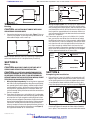
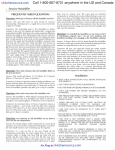
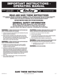
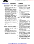
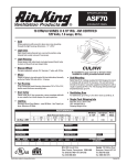
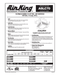
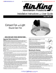
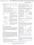
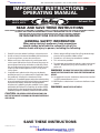
:: bathroomsource.com
Call 1-800-667-8721 anywhere in the US and Canada - www.bathroomsource.com
IMPORTANT INSTRUCTIONS OPERATING MANUAL
Models:
ASLC50, ASLC50FL
ASLC70, ASF70
Exhaust Fan
READ AND SAVE THESE INSTRUCTIONS
READ CAREFULLY BEFORE ATTEMPTING TO ASSEMBLE, INSTALL, OPERATE OR MAINTAIN THE PRODUCT DESCRIBED. PROTECT
YOURSELF AND OTHERS BY OBSERVING ALL SAFETY INFORMATION. FAILURE TO COMPLY WITH
INSTRUCTIONS COULD RESULT IN PERSONAL INJURY AND/OR PROPERTY DAMAGE!
RETAIN INSTRUCTIONS FOR FUTURE REFERENCE.
GENERAL SAFETY INFORMATION
When using electrical appliances, basic precautions
should always be followed to reduce the risk of fire,
electric shock and injury to person, including the following:
1. Read all instructions before installing or using exhaust fan.
2. Use this unit only in the manner intended by the manufacturer.
If you have questions, contact the manufacturer.
3. Before servicing or cleaning the unit, switch power off at
service panel and lock the service disconnecting means to
prevent power from being switched on accidentally. When
the service disconnecting means cannot be locked, securely
fasten a prominent warning device, such as a tag, to the
service panel.
4. Installation work and electrical wiring must be done by
qualified person(s) in accordance with all applicable codes
and standards, including fire-related construction.
5. Sufficient air is needed for proper combustion and exhausting
of gases through the flue (chimney) of fuel burning equipment
to prevent back drafting. Follow the heating equipment
manufacturer’s guideline and safety standards such as those
published by the National Fire Protection Association (NFPA)
and the American Society for Heating, Refrigeration, and Air
Conditioning Engineers (ASHRAE), and the local code authorities.
6. When cutting or drilling into wall or ceiling, do not damage
electrical wiring and other hidden utilities.
7. Ducted fans must always be vented to the outdoors.
8. This unit must be grounded.
9. To avoid motor bearing damage and noisy and/or unbalanced
impellers, keep drywall spray, construction dust, etc. off
power unit.
WARNING: TO REDUCE THE RISK OF FIRE, ELECTRIC SHOCK,
DO NOT USE THIS FAN WITH ANY SOLID-STATE SPEED CONTROL
DEVICE.
10. Acceptable for use over a bathtub or shower when installed
in a GFCI protected branch circuit.
11. NEVER place a switch where it can be reached from a tub or
shower.
WARNING: DO NOT USE IN KITCHENS
CAUTION: FOR GENERAL VENTILATING USE ONLY. DO
NOT USE TO EXHAUST HAZARDOUS OR EXPLOSIVE MATERIALS
AND VAPORS.
SAVE THESE INSTRUCTIONS
210572052 Rev. A 7-05
Air King at
::bathroomsource.com
powered by ::kitchensource.com
:: bathroomsource.com
Call 1-800-667-8721 anywhere in the US and Canada - www.bathroomsource.com
INSTALLATION INSTRUCTIONS
CAUTION: MAKE SURE POWER IS SWITCHED OFF AT
SERVICE PANEL BEFORE STARTING INSTALLATION.
Housing
SECTION 1
Preparing the Exhaust Fan
1. Unpack fan from the carton and confirm that all pieces are
present. In addition to the exhaust fan you should have:
1 - Grill with Light Lens
4 - Mounting Rails
1 - Damper Assembly (attached)
1 - Instruction/Safety Sheet
2. Remove the fan’s venturi assembly, which is secured in place
with one screw through the venturi (Figure 1). This is a captive
screw and will stay installed in the venturi. Keep the venturi
assembly and the grill in the carton until needed so they do
not get damaged or lost.
Joist
Mounting Rails
Figure 3
2. Mounting Tab Installation: Using the gauge on the fan’s
housing, line up housing so that it will be flush with the
finished ceiling. Position the fan so that the tabs rest flat
against the joist and secure with four nails (not provided) to
ensure proper installation (Figure 4).
5/8"
1/2"
3/8"
Screw
1/4"
Figure 4
Figure 1
SECTION 3
3. Choose the location for your fan. To ensure the best air and
sound performance, it is recommended that the length of
ducting and the number of elbows be kept to a minimum, and
that insulated hard ducting be used. Larger duct sizes will
reduce noise and airflow restrictions. This fan will require at
least 6" of clearance in the ceiling or wall, and will mount
through drywall up to 3/4" thick. The
fan can be mounted directly to the
joist using the mounting tabs on the
side of the housing or between 16"
on center joists using the 4 provided
mounting rails.
4. Select the most convenient
electrical knockout and remove
using a straight-blade screw driver
Figure 2
(Figure 2).
SECTION 2
Existing Construction
1. Mounting Rail Installation: Set housing in position between
the joist and trace an outline onto the ceiling material (Figure
5). Set housing aside and cut opening, being careful not to
cut or damage any electrical or other hidden utilities. Install
the rails on the housing and position the housing in the
previously cut hole so that it is flush with the finished ceiling.
Secure the ends of the rails to the joists (Figure 3).
Figure 5
New Construction
1. Mounting Rail Installation: Install the rails on the housing
and position the housing next to the joist. Using the gauge
on the fan’s housing, line up housing so that it will be flush
with the finished ceiling. Secure the ends of the rails with
screws or nails (not included) to the joists and slide the
housing into the final position (Figure 3).
1. Mounting Tab Installation: Position housing against the joist
and trace an outline of the housing onto the ceiling material
(Figure 6). Set housing aside and cut opening, being careful
not to cut or damage any electrical or other hidden utilities.
Place housing next to the joist and insure that it is flush with
the finished ceiling. Secure with four nails (not provided) to
ensure proper installation (Figure 4).
210572052 Rev. A 7-05
Air King at
::bathroomsource.com
powered by ::kitchensource.com
:: bathroomsource.com
Call 1-800-667-8721 anywhere in the US and Canada - www.bathroomsource.com
Supply
from
house
Figure 8
Figure 6
SECTION 4
Ducting
CAUTION: ALL DUCTING MUST COMPLY WITH LOCAL
AND NATIONAL BUILDING CODES.
1. Connect the ducting to the fan’s duct collar (Figure 7). Secure
in place using tape or screw clamp. Always duct the fan to
the outside through a wall or roof cap.
Figure 7
NOTE: If damper detaches from unit, reattach by snapping the
collar back onto the unit. It is designed to only fit one way.
Ground
White
Hot (Black)
2. Wiring Fan/Light together: Run wiring from an approved wall
switch carrying the appropriate rating. One neutral (white),
one ground (green or bare copper), and one hot (black lead
connected to the switch). Secure the electrical wires to the
housing with an approved electrical connector. Make sure
you leave enough wiring in the box to make the connection
to the fan’s receptacle.
2a. From where you have access to inside the fan’s junction
box, connect the one White wire from the house to both
the White wire from the fan’s light receptacle and the White
wire from the fan’s exhaust receptacle. Connect the Black
wire from the wall switch to both the Black wire from the
fan’s light receptacle and the Black wire from the fan’s
exhaust receptacle. Connect the ground wire from the house
to the Green wire from the fan’s grounding screw (Figure
9). Use approved methods for all connections.
Supply
from
house
Ground
White
SECTION 5
Wiring
CAUTION: MAKE SURE POWER IS SWITCHED OFF AT
SERVICE PANEL BEFORE STARTING INSTALLATION.
CAUTION: ALL ELECTRICAL CONNECTIONS MUST BE
MADE IN ACCORDANCE WITH LOCAL CODES, ORDINANCES,
OR NATIONAL ELECTRICAL CODE. IF YOU ARE UNFAMILIAR
WITH METHODS OF INSTALLING ELECTRICAL WIRING, SECURE
THE SERVICES OF A QUALIFIED ELECTRICIAN.
1. Wiring Fan/Light Independently: Run wiring from an approved
wall switch carrying the appropriate rating. One neutral (white),
one ground (green or bare copper), and two hot (black lead
connected to the switch). Secure the electrical wires to the
housing with an approved electrical connector. Make sure
you leave enough wiring in the box to make the connection to
the fan’s receptacle.
1a. From where you have access to inside the fan’s junction box,
connect the one White wire from the house to both the White
wire from the fan’s light receptacle and the White wire from
the fan’s exhaust receptacle. Connect the first Black wire from
the wall switch to the Black wire from the fan’s light receptacle.
Connect the second Black wire from the house to the fan’s
exhaust receptacle. Connect the ground wire from the house
to the Green wire from the fan’s grounding screw (Figure 8).
Use approved methods for all connections.
210572052 Rev. A 7-05
Figure 9
Hot (Black)
SECTION 6
Completing the Installation
1. Reinstall the fan’s venturi by holding it at approximately a 45
degree angle, hook the two tabs on the venturi into the slots
on the housing and secure in place by tightening the venturi
screw. Rotate the blower wheel by hand to ensure it spins
freely. Now plug the fan motor into the receptacle (Figure 10).
Figure 10
2. Install the grill/lens/light reflector, by first removing the lens
from the grill (there are two tabs on either side that hold the
lens in place). Then remove the acorn nut and the lock washer
Air King at
::bathroomsource.com
powered by ::kitchensource.com
:: bathroomsource.com
Call 1-800-667-8721 anywhere in the US and Canada - www.bathroomsource.com
which are installed on the reflector mounting bolt in the fan
housing. Adjust the height of the reflector mounting bolt so that
the grill will be tight up against the finished ceiling and less than
1/4" of the reflector mounting bolt protrudes through the reflector.
Secure the reflector bolt’s position by tightening the factory
installed nut against the motor clip (Figure 11).
Motor Clip
Mounting Bolt
Nut
Reflector
Grill
Lock Washer
Acron Nut
Figure 11
Lens
Tabs
CAUTION: FAILURE TO SECURE THE REFLECTOR BOLT MAY
RESULT IN A RATTLING OR HUMMING NOISE.
3. After the reflector bolt is secure, raise the grill/reflector up
into position, and plug the reflector into the appropriate
receptacle. Secure the assembly to the reflector bolt using
the acorn nut and lock washer. Install the appropriate bulb
(not included) specific to your model:
ASLC50/ASLC70: 100 watt maximum, type A19 medium
base incandescent bulb.
ASLC50FL: 13 watt maximum, 2 pin quad, PL-C compact
flourescent bulb.
ASF70: 26 watt maximum, triple 4 pin PL flourescent bulb.
Reinstall the lens into the grill (Figure 12).
SECTION 7
Use and Care
CAUTION: MAKE SURE POWER IS SWITCHED OFF AT
SERVICE PANEL BEFORE SERVICING THE UNIT.
1. Cleaning the Grill: Remove grill and use a mild detergent,
such as dishwashing liquid, and dry with a soft cloth. NEVER
USE ANY ABRASIVE PADS OR SCOURING POWDERS.
Completely dry grill before reinstalling. Refer to instructions
in Section 6 Completing the Installation, to reinstall grill.
2. Cleaning the Fan Assembly: Unplug the motor cord and light
cord from receptacles and loosen the venturi screw to remove
the venturi from the unit. Wipe all parts with a dry cloth or
gently vacuum the fan. NEVER IMMERSE ELECTRICAL PARTS
IN WATER. Refer to instructions in Section 6 Completing the
Installation, to reinstall venturi.
CAUTION: ALLOW BULB TO COOL BEFORE REPLACING.
3. Changing the Light Bulb: Disconnect power to the unit.
Remove the light lens by squeezing at the tabs and pulling
down (Figure 13). Remove light bulb and refer to instructions
in Section 6 Completing the Installation, to complete the light
bulb change and installation of light lens.
Tabs
Figure 13
Figure 12
4. Restore power and test your installation.
210572052 Rev. A 7-05
Air King at
::bathroomsource.com
powered by ::kitchensource.com