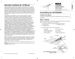
1
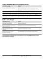
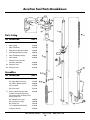
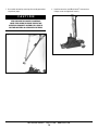
Stand-up Insulation Attachment Tool
Owner’s Manual
IMPORTANT!
Save this manual
and read it in
full before use.
RP10045-250-OP
153 BOWLES ROAD
AGAWAM, MA 01001
800. 633.3800
WWW.OLYFAST.COM
WA R N I N G
When using electric tools, safety precautions should always be followed to reduce the risk of fire, electric shock, and personal
injury. Failure to follow these instructions can result in severe personal injury.
Read All Instructions
General Safety Considerations
3. Never allow visitors to contact the tool or extension cords.
All visitors should be kept away from the work area.
1. Before using the tool, become familiar with all of the operating instructions.
4. Don’t abuse the tool:
2. Don’t use the tool for purposes not intended.
• Keep handle dry, clean and free from oil and grease.
3. Failure to wear safety glasses with side shields can result in
severe eye injury or blindness. Always wear safety glasses
with side shields that conform to ANSI Standard Z87.1.
• Never carry the tool by the cord or yank it to disconnect
from the receptacle.
4. Keep the work area clean and well lit. Dark, cluttered work
areas and benches invite injuries.
• Always store an idle tool in a dry, high or lockedup place.
5. Dress properly! Never operate the tool while wearing loose
clothing or jewelry. They can be caught in moving parts.
• Always disconnect the tool when it’s not in use or
before servicing.
6. Maintain proper footing and balance at all times:
• To avoid unintentional starting, never carry a plugged-in
tool with finger on the switch. Be sure the switch is OFF
when plugging in.
• Always keep the cord from heat, oil and sharp edges.
• Don’t use the tool in an awkward position.
• Don’t overreach.
5. Maintain the tool with care. Check damaged parts. Before
further use of the tool, a guard or other part that is damaged
should be carefully checked to determine that it will operate
properly and perform its intended function. Check for
alignment of moving parts, binding of moving parts, breakage of parts, mounting and any other conditions that may
affect its operation. A guard or other part that is damaged
should be properly repaired or replaced by an authorized
service center unless otherwise indicated elsewhere in
this instruction manual. Have inoperative switches replaced
by an authorized service center. Do not use the tool if the
switch does not turn the tool ON and OFF.
7. Stay alert! Watch what you are doing! Use common
sense! Do not operate tool when you are tired!
Safety Procedures For Electric Tools
1. Guard against electric shock.
2. Consider work area environment:
• Never operate tool in damp or wet locations.
• Prevent body contact with grounded surfaces, such
as pipes.
• Use only extension cords intended for outdoor use and
so marked.
• When servicing double insulated tool, use identical
replacement parts.
• Wear rubber gloves and non-skid footwear when working outdoors.
• Keep the tool clean for better and safer performance.
• Inspect the tool cord periodically and, if damaged, have
it repaired by an authorized service facility.
• Don’t expose power tools to rain.
• Never operate tool in the presence of flammable liquids
or gases.
• Inspect the extension cord periodically and replace it if
it’s damaged.
SAVE THESE INSTRUCTIONS
OMG ROOFING PRODUCTS
800 . 633 . 3800
1
WWW.OLYFAST.COM
Table of Contents
General Safety Instructions. . . . . . . . . . . . . . . . . . . . . . . . . . . . . . . 1
Warranty and Remedy, Wire Gauge . . . . . . . . . . . . . . . . . . . . . . . 3
Operating Instructions
General . . . . . . . . . . . . . . . . . . . . . . . . . . . . . . . . . . . . . . . . . . . . . 3
Loading Plates. . . . . . . . . . . . . . . . . . . . . . . . . . . . . . . . . . . . . . . 3
Operating the Tool . . . . . . . . . . . . . . . . . . . . . . . . . . . . . . . . . . . 3
Adjustments
Depth Adjustment. . . . . . . . . . . . . . . . . . . . . . . . . . . . . . . . . . . . 4
Parts Removal and Replacement
Feed Tube Removal and Replacement . . . . . . . . . . . . . . . . . . 5
Screw Gun Removal and Replacement . . . . . . . . . . . . . . . . . 5
Drive Shaft, Hex Pin Insert and Bit(s) . . . . . . . . . . . . . . . . . . . 5
ACCUTRAC
Ejector Blade Insert Discs . . . . . . . . . . . . . . . . . . . . . . . . . . . . 6
Part Number 6626910
Clearing Fastener and Plate Jams . . . . . . . . . . . . . . . . . . . . . . . . . 6
Cleaning Procedure . . . . . . . . . . . . . . . . . . . . . . . . . . . . . . . . . . . . . 6
Troubleshooting. . . . . . . . . . . . . . . . . . . . . . . . . . . . . . . . . . . . . . . 7–9
Parts List. . . . . . . . . . . . . . . . . . . . . . . . . . . . . . . . . . . . . . . . . . . 10–11
Cleaning and Maintenance Procedures
General . . . . . . . . . . . . . . . . . . . . . . . . . . . . . . . . . . . . . . . . . . . . 12
Dismantling the Tool . . . . . . . . . . . . . . . . . . . . . . . . . . . . . 13–16
© Copyright 2009 OMG, Inc. All rights reserved.
OMG ROOFING PRODUCTS
800 . 633 . 3800
2
WWW.OLYFAST.COM
Warranty and Remedy
Notice
ALL WARRANTIES OF THE PRODUCTS DESCRIBED HEREIN,
EXPRESS OR IMPLIED, INCLUDING THE WARRANTIES OF
MERCHANTABILITY AND FITNESS FOR PARTICULAR PURPOSES
ARE SPECIFICALLY EXCLUDED, EXCEPT FOR THE FOLLOWING:
OMG Roofing Products will repair or replace, at its sole option,
any tool part which within 90 days after sale by OMG Roofing
Products or its distributors, is found by OMG Roofing Products
to be defective in material or workmanship, normal wear and
tear excluded.
The AccuTrac tool was designed for use with 3” square plates
(insulation) and approved fasteners manufactured by OMG
Roofing Products. OMG Roofing Products is not responsible
for damage to the tool and/or improper installation as a result
of using fasteners and/or plates other than described above.
Important Note Before Using Tool
Extension cords must be of adequate wire size (AWG or
American Wire Gauge) for safety, to prevent loss of power
and to avoid overheating. To determine the minimum wire
size required, refer to the following chart:
THIS IS THE SOLE WARRANTY OF OMG ROOFING PRODUCTS
AND THE SOLE REMEDY AVAILABLE TO DISTRIBUTOR
OR BUYER.
Cord Length
in Feet
25'
50'
75'
100'
125'
150'
Wire Size
(Gauge)
18
16
14
14
12
12
Operating Instructions
General
Operating the Tool
1. Use only with 3" square plates (insulation) and approved
fasteners manufactured by OMG Roofing Products.
1. Drop one screw, point down, into the funnel.
2. Fully compress the AccuTrac to allow a plate to be ejected
from the stack and moved into position for attaching to
the insulation. At this point the screw will be released
and will drop down the feed tube. Allow the tool to fully
extend, then drop another screw into the funnel. It will be
contained at the mouth of the funnel until needed.
2. At the beginning of each day, wipe down the tubes and the
bottom of the ejector plate. Lubricate the linkage and the
plate ejector blade, if needed, then unlatch the tool.
3. Load the plate hold with the proper plates.
4. Make sure the screw gun is in the FORWARD mode and is
NOT in the locked ON position. Connect the tool to the
proper power source.
3. Lock the screw gun trigger in the ON position. Using the
lock will keep the screw gun running cooler. Push the tool
downward to drive the screw through the insulation until it
contacts the deck. Continue to hold down on the tool until
the plate is fully seated.
5. At the end of the day, remove any dust accumulation from
the tubes and the bottom of the ejector blade.
6. Lubricate all moving parts. Excess lubricant will evaporate
overnight.
7. Re-latch the tool and store it in its case.
4. Allow the tool to retract to its original position. This motion
causes the next plate to be ejected from the stack and
the second screw to drop down the feed tube.
Loading Plates
5. Check the plate to make sure it is properly seated and
adjust fastener depth if necessary.
6. Pull the tool back on its wheels, push it to the next plate
application position on the roof and repeat the “tool use”
instructions.
1. Push and turn the plate retaining handle counterclockwise
and lift the retaining rod to its extended position.
2. Remove the pre-packaged plates from the box. Align the
notch in the plates with the projection on the back side of
the plate hold.
3. Drop the plates into the hold, slide the retaining rod down,
then push and turn it clockwise to lock the handle in position.
OMG ROOFING PRODUCTS
800 . 633 . 3800
3
WWW.OLYFAST.COM
Adjustments
Depth Adjustment
Over-driving can cause the screw to strip out the metal deck
and not hold. The tool should be adjusted to make the plate
snug so that it does not spin freely on the surface. The plate
should not be so tight as to cause it to deform.
To avoid overdriving, it is suggested that the operator
deliberately start with the adjustment set too loose and
then slowly make adjustments until the desired tightness
is reached.
Adjustments are made using the large ring located
on the upper body tube of the tool. Moving
the ring upwards towards the screw gun
will make the screw deeper (tighter).
Note: If you are unable to make the
plate “snug” through adjusting the
depth adjustment nut, make sure that
the screw gun is in the forward position (not reverse).
OMG ROOFING PRODUCTS
800 . 633 . 3800
4
WWW.OLYFAST.COM
Parts Removal and Replacement
Always Use OMG Roofing Products Replacement Parts
Feed Tube Removal and Replacement
Drive Shaft, Hex Pin Insert and Bit(s)
1. Disconnect the upper link from the feed tube assembly by
sliding the black plastic bushings inward and push the
upper link forward to disengage. Repeat the process for
the opposite upper link.
1. Remove the screw gun and drive shaft assembly as
described above. Separate the screw gun from the drive
shaft by simply pulling on the shaft from the screw gun.
2. Carefully inspect the drive shaft, spring pin hex insert,
Phillips cap and bit assemblies for excessive wear, cracks
and/or damage of any kind. If either the shaft, spring pin
hex insert, Phillips cap or bits require replacing, use
assembly part number 6634910 (Universal drive shaft),
6606910 (spring pin hex insert), 6722910 (1.4” length
reversible hex bit), 6637910 (Phillips cap) and 6624910
(Phillips bit insert).
2. The tool can now be removed from the base by pulling up
on the tool.
3. Once the tool is separated from the base, you can remove
the feed tube from the upper tube by pulling on the springloaded retention pin and separating it from the bracket on
the upper tube. The feed tube should now release from the
tool.
3. If only the drive bit
needs to be replaced,
first locate where the
spring pin insert holds
the Phillips cap or hex
bit, then press in on
the spring pin to
affect release.
4. To re-install the feed tube, align the lower end so that the
“ears” engage the notches of the lower tube.
5. Angle the feed tube towards the upper tube and re-install
the retention pin into the bracket.
6. Re-attach the upper links by sliding the black plastic bushings inward and connecting the links.
4. When replacing a
Phillips bit, insert a new
bit into the Phillips cap
then fit it over the end
of the drive shaft, press in on the spring pin while aligning
the hole in the cap or bit and push in until the spring pin
snaps into place.
WA R N I N G
The nosepiece is not to be removed!
1. The nosepiece is under spring-loaded pressure. Attempting
to remove the nosepiece could cause personal injury.
2. See warning sticker on tool!
3. Contact 1. 800 . 633. 3800 to locate your nearest authorized
5. To re-install the hex drive, simply fit it over the end of the
drive shaft, press in on the spring pin while aligning the hole
in the hex drive and push in until the spring snaps into place.
OMG Roofing Products AccuTrac Distributor and Service
Center.
6. Re-install the drive shaft assembly into the screw gun
making sure it snaps into place.
Screw Gun Removal and Replacement
7. Lower the drive shaft/screw gun assembly into the AccuTrac
tool and rotate the screw gun clockwise until tight.
1. Loosen the star knob assembly on the screw gun motor
clamp and rotate the screw gun in the counterclockwise
direction until the threads disengage.
8. Rotate the screw gun to properly align for operation. When
set, securely tighten the star knob on the motor clamp
assembly. Do not over-tighten the screw gun.
2. The screw gun must be raised straight up to allow the
screw gun and the attached drive shaft to be removed
from the tool.
3. When the assembly is free, pull the drive shaft from the
screw gun. To re-attach the screw gun, reverse the above
process. Be careful not to over-tighten the screw gun as
this may cause the nosepiece of the screw gun to fall off.
OMG ROOFING PRODUCTS
800 . 633 . 3800
5
WWW.OLYFAST.COM
Ejector Blade Insert Discs
Clearing Fastener and Plate Jams
1. If the ejector blade insert discs are worn and need to be
replaced, the ejector blade assembly must first be
removed from the tool.
1. Remove the feed tube (follow directions as described on
page 5 of this manual) to access the junction where most
fastener jams occur. You should be able to clear the fastener(s) from the nosepiece.
2. Remove the two socket head cap screws that connect the
ejector blade to the drive bar. Withdraw the ejector blade
and take the assembly to a clean working surface.
2. In some cases it may be necessary to remove the jaws in
the end of the nosepiece to fully access the jam. The jaws
can be removed by removing the O-ring that holds them in
the nosepiece.
3. The ejector blade insert discs are fastened to the blade
with two socket head cap screws. The screws are secured
with a retaining compound and they must be heated
before they can be removed. This is best done if heat is
applied with a small propane torch.
3. For clearing plate jams, first make sure the tool is completely
retracted in its full upright position. This may require that
you tug upwards on the tool. Most likely, a plate will shuttle
into the proper place.
4. If the plate remains jammed, remove the stack of plates
from the holder. First, attempt to cycle the ejector blade
by quickly compressing the tool downward. The jammed
plate should dislodge. If it does not, you will need to
remove the plate manually as it is most likely stuck underneath the gate. This may require a pair of pliers. Take care
not to damage the ejector blade or gate mechanism.
C A U T I O N
USE CARE TO AVOID PERSONAL INJURY OR
HEAT DAMAGE TO SURROUNDINGS.
4. Remove the two screws and the two insert discs and
replace with new discs.
5. Once the jammed plate is removed, re-install the plates in
the plate hold.
5. Coat the thread of the screws with retaining compound
and securely tighten them. Allow 24 hours for the compound to cure.
Cleaning Procedure
6. Insert the ejector blade into the tool, align it with the drive
blade, insert and securely tighten the two socket head cap
screws to fasten the ejector blade to the drive blade.
1. The linkages, ejector blade and housing should be cleaned
weekly with a commercial solvent.
2. Special attention should be paid to the linkage connections
and the groove in the casting (black base) that holds the
ejector blade. Be sure these grooves are free of burrs,
asphalt and dirt.
3. Once clean, re-lubricate the ejector blade track with
Tri-Flow or a Teflon-based lubricant.
4. The gate should also be checked periodically to ensure it is
not sticking. If it is, clean with a degreaser and re-lubricate.
OMG ROOFING PRODUCTS
800 . 633 . 3800
6
WWW.OLYFAST.COM
Troubleshooting Problems
Problem: Plates Not Feeding Smoothly or Completely
POTENTIAL CAUSE
REMEDY
Plates have been inserted upside down
Remove plates from plate hold and reinstall so the notch in the plate fits the
extrusion in the plate hold.
Dirty ejector blade and/or guides
Clean the ejector blade and/or guides with degreaser.
Gate is sticking
Clean the gate with a degreaser.
Ejector blade screws are loose
Remove the screws, clean the screws and threaded holes.
Apply Loctite 242 and reinstall screws.
Ejector blade insert screws are loose
Remove the screws, clean the screws and threaded holes.
Apply Loctite 242 and reinstall screws.
Ejector blade insert undercut is clogged
Clean out the undercut.
Plate retaining spring is not
completely seated
Turn the handle clockwise and gently pull upward.
Nosepiece is bent
Call 1. 800 . 633. 3800 for service. Do not attempt to remove nosepiece.
Plate stop screws are loose
Remove the screws, clean the screws and threaded holes. Apply Loctite 242
and reinstall screws.
Plate rod is not completely seated
Turn handle clockwise and gently pull upward.
Problem: Missing or Skipped Plates
POTENTIAL CAUSE
REMEDY
Plate is bent or previously used
Disconnect upper links from the feed tube and slide ejector blade forward.
Remove suspect plate(s). Reconnect upper links and continue.
Ejector blade insert disc(s) is/are missing
Replace missing insert.
Incorrect plates are being used
Use only OMG Roofing Products AccuTrac plates.
Ejector blade insert disc undercuts are
dirty/clogged
Clean out undercuts.
OMG ROOFING PRODUCTS
800 . 633 . 3800
7
WWW.OLYFAST.COM
Problem: Screws Not Feeding or Installing Properly
POTENTIAL CAUSE
REMEDY
Wrong bit installed
Use only AccuTrac drive bits.
#3 Phillips drive bit 6624910 — 1.4” reversible hex bit 6722910.
Obstructed feed tube
Clean or replace the feed tube.
Two screws jammed in feed tube
or nosepiece
Remove feed tube and dislodge screws.
Screws are too long
Screws must not exceed 6” in length.
Nosepiece jaws are installed upside down
Jaws must be installed with beveled edge facing upward.
Drive shaft collar is broken
Replace drive shaft.
Anti-jam mechanism is dirty or stuck
Clean anti-jam mechanism. Check to see if springs are activating properly.
Replace if needed.
Problem: Plate Not Seating Tightly
POTENTIAL CAUSE
REMEDY
Improper depth adjustment
Tighten the depth adjustment.
Screw gun is in reverse
Make sure switch is in forward position.
Incorrect drive bit, or worn/broken bit
Check to make sure correct drive bit is installed. Replace worn or broken
drive bits.
Nosepiece jaws are installed upside down
Jaws must be installed with beveled edge facing upward.
Screw gun not properly installed or
fully tightened
Check screw gun; tighten if necessary.
Excessive build-up of material on
wheels/casting
Remove built-up material.
Obstruction in tubes and/or casting
Check upper and lower tubes and casting, remove any obstructions.
OMG ROOFING PRODUCTS
800 . 633 . 3800
8
WWW.OLYFAST.COM
Problem: Tool Will Not Retract into Full Upward Position
POTENTIAL CAUSE
REMEDY
Operator is not allowing tool to fully retract
Downward pressure on tool must be fully released after the plate has
been fastened. Tool should “spring” up into correct position. If necessary,
tug upwards.
Ejector blade or tubes are dirty
Clean and oil ejector blade and tubes.
Nosepiece is bent or damaged
Call 1. 800 . 633. 3800 for service. Do not attempt to remove nosepiece.
Fastener wedged between feed tube
and nosepiece
Remove feed tube and clear fastener jam.
Problem: Tool is Sluggish
POTENTIAL CAUSE
REMEDY
Ejector blade needs lubricating
Lubricate the ejector blade.
Dirty upper and lower tubes, ejector blade
guides and drive bar slots
Remove debris. Clean all parts with a degreaser and lubricate.
Upper and/or lower tubes are bent
or damaged
Replace worn or damaged tubes as needed.
Nosepiece retaining screw is worn or
the nosepiece is damaged
Call 1. 800 . 633. 3800 for service. Do not attempt to remove nosepiece.
If you have followed the recommendations above, but your problems persist, please call the OMG Roofing Products Technical
Services Department at 1. 800 . 633 . 3800.
OMG ROOFING PRODUCTS
800 . 633 . 3800
9
WWW.OLYFAST.COM
AccuTrac Tool Parts Breakdown
Parts Listing
KEY DESCRIPTION
PART #
1
Screw Gun, DeWalt, DW284
6319910
2
Upper Spring
6291910
3
Upper Tube Body
6641910
4
Depth of Drive Adjustment Knob
6288910
5
Feed Tube Mounting Assembly
6649910
6
Lower Tube Body (exterior)
6650910
7
Lower Spring
6299910
8
Nosepiece (not removable
from lower tube body)
6629910
9A Nosepiece Jaws
6284910
9B O-Ring for Jaws
6285910
Assemblies
KEY DESCRIPTION
A
B
PART #
Screw Gun Mounting Clamp Assembly
A(1) Upper Mount w/Screws
A(2) Nutless Mounting Collar
A(3) Star Knob
A(4) Latch Cable
Universal Drive Shaft Assembly
Includes Drive Shaft B(1), Spring
Pin Hex Insert B(2), #3 Phillips Insert
Bit and Phillips Cap
B(1) Spring Pin Hex Insert
B(2) #3 Phillips Insert Bit
B(3) Phillips Cap
1.4” Length Reversible Hex Bit
#3 Square Drive Bit
6377910
6639910
6787910
6671910
6634910
6606910
6624910
6637910
6722910
6693910
OMG ROOFING PRODUCTS
800 . 633 . 3800
10
WWW.OLYFAST.COM
Assemblies
Other Parts & Accessory Listing
KEY DESCRIPTION
C
D
PART #
PART #
Dual Lever Anti-Jam Feed Tube Assembly
6791910
10
Base Casting
C(1) Upper Anti-Jam Lever & Spring
6784910
11
Gate with Plate Hold Mechanism
C(2) Lower Anti-Jam Lever & Spring
6785910
12
Plate Stop
C(3) Pull Pin & Spring (attaches Feed Tube
to Upper Tube Body)
13
Flexible Plate Alignment Shaft
6724910
6786910
14
Rear Wheels with Axle
6701910
C(4) Lever Actuator Rod
6788910
NA AccuTrac Case (not shown)
6631910
C(5) Actuator Nub
6790910
Ejector Blade Assembly, 3" Square
6653910
D(1) Ejector Blade Plate
6675910
D(2) Ejector Blade Insert
6640910
D(3) Ejector Blade Drive Bar
6632910
D(4) Drive Bar Retaining Screws
6643910
Quick Release Linkage Assembly
6700910
3
E(1) Upper Links
—
E(2) Lower Linkage Bars
—
E(3) Sliding Bushings & Springs
• Bushings
• Springs
8310020
WA R N I N G
ALL PARTS MUST BE PERIODICALLY INSPECTED
AND REPLACED IF WORN OR BROKEN.
FAILURE TO DO THIS CAN AFFECT A PRODUCT’S
OPERATION AND CAUSE PERSONAL INJURY.
—
6691910
6692910
OMG ROOFING PRODUCTS
—
—
6645910
D(5) Socket Head Cap Screw, ⁄4"-28 x ⁄4"
1
E
KEY DESCRIPTION
800 . 633 . 3800
11
WWW.OLYFAST.COM
Cleaning and Maintenance Procedures
General
1
This procedure is a simple and effective way to clean your
AccuTrac tool to maintain reliable operation. Regular cleaning
and lubrication will also extend part life and ensure smooth
operation.
The following items are needed for proper maintenance:
1. Wire brush, putty knife, cloth rag and an aerosol
“safety solvent.”
2. A Teflon-based lubricating oil, i.e., Tri-Flow™.
3. Allen wrenches ( 3⁄8 " and 3⁄16") and Loctite® Removable
Threadlocker (Blue Loctite).
2
3
OMG ROOFING PRODUCTS
800 . 633 . 3800
12
WWW.OLYFAST.COM
Dismantling the Tool
Dismantling the AccuTrac for routine maintenance:
2. Once the tool is separated from the base you can remove
the feed tube from the upper tube by pulling on the
spring-loaded retention pin and separating it from the
bracket on the upper tube. The feed tube should now
release from the tool.
1. Disconnect the upper link from the feed tube assembly by
sliding the black plastic bushings inward and push the
upper link forward to disengage. Repeat the process for
the opposite upper link. The tool can now be removed from
the base by pulling up on the tool.
1a
2a
1b
2b
OMG ROOFING PRODUCTS
800 . 633 . 3800
13
WWW.OLYFAST.COM
3. Wipe nosepiece with clean cloth.
5. Inspect the wheeled-base assembly for build-up of
asphalt, adhesives or debris. Spray with safety solvent
and remove foreign material from the linkage and track
ejector blade. If your AccuTrac has been used for extended
periods of operation or under extremely dirty operating
conditions, it may be necessary to soak the wheeled-base
assembly in a pan of safety solvent or parts cleaning tank.
3
4. Wipe lower tube with clean cloth.
4
5a
5b
OMG ROOFING PRODUCTS
800 . 633 . 3800
14
WWW.OLYFAST.COM
6. Prior to reassembling the tool, lubricate the linkage and
ejector blade track using a Teflon-based lubricant, i.e.,
Tri-Flow™ making sure to wipe excess lubricant from tool.
5c
6a
5d
6b
OMG ROOFING PRODUCTS
800 . 633 . 3800
15
WWW.OLYFAST.COM
7. Reassemble the tool by reversing disassembly procedures
on previous pages.
8. Use Allen wrenches and (Blue) Loctite® to ensure that
linkage screws are tightened securely.
C A U T I O N
8
FEED TUBE MUST BE PROPERLY HOOKED ON
LOWER TUBE CASING TO ENSURE PROPER TOOL
OPERATION. INCORRECT ASSEMBLY WILL LEAD TO
FASTENER MISFEEDS OR OVERDRIVEN FASTENERS.
7
OMG ROOFING PRODUCTS
800 . 633 . 3800
16
WWW.OLYFAST.COM
Herramienta Ergonómico para la Fijación de Aislamiento
Manual
¡IMPORTANTE!
Guarde este manual y
leyólo completamente
antes del uso.
RP10045-250-OP
153 BOWLES ROAD
AGAWAM, MA 01001
800. 633.3800
WWW.OLYFAST.COM
A L E R TA
Cuando se usan herramientas eléctricas, deben siempre seguirse las precauciones de seguridad para reducir el riesgo de incendio,
sacudida eléctrica, y daño personal. Si no se siguen estas instrucciones el resultado puede ser lesiones personales severas.
Lea Todas las Instrucciones
Consideraciones Generales de Seguridad
4. No abuse de la herramienta:
• Mantenga el mango de la herramienta seco, limpio y
libre de gasolina o grasa.
• Nunca cargue la herramienta por el cordón y no le dé
un tirón para desconectarlo del receptáculo.
• Mantenga siempre el cordón alejado del calor, gasolina
o de bordes afilados.
• Siempre guarde una herramienta en desuso en un lugar
seco, alto o cerrado con llave.
• Siempre desconecte la herramienta cuando no esté en
uso o antes de darle mantenimiento.
• Para evitar que la herramienta empiece a trabajar de
forma no intencional, nunca transporte una herramienta
que esté conectada con el dedo en el interruptor.
Asegúrese que el interruptor esté en la posición
APAGAR (off) cuando la conecte.
5. Mantenga la herramienta con cuidado. Inspeccione si hay
partes dañadas. Antes de volver a usar la herramienta, la
cubierta de protección u otra parte que esté dañada debe
ser revisada cuidadosamente para determinar que volverá
a operar de forma debida y que volverá a operar la función
que se espera. Inspeccione que las partes móviles se
encuentren alineadas, y que se encuentren vinculadas,
revise si hay partes rotas, rozando otras o si existe
cualquier otra condición que pueda afectar su operación.
La cubierta de protección u otra parte dañada debe ser
reparada de forma apropiada o reemplazada en un centro
de servicio autorizado a menos que esté indicado de otra
forma en cualquier parte en este manual de instrucción.
Reemplace los receptáculos que no funcionan en un
centro de servicio autorizado. No use la herramienta si el
interruptor no hace funcionar a la herramienta en la
posición ENCENDER (on) o APAGAR (off).
• Cuando le dé mantenimiento a la herramienta con
aislamiento doble, use partes idénticas de reemplazo.
• Mantenga la herramienta limpia para un mejor y más
seguro rendimiento.
• Inspeccione el cordón de la herramienta
periódicamente y si está dañado, hágalo reparar en un
centro de servicio autorizado.
• Inspeccione el cordón de extensión periódicamente y
reemplácelo si está dañado.
1. Antes de usar la herramienta, familiarícese con todas las
instrucciones de operación.
2. No use la herramienta para un propósito no intencionado.
3. Si no se usan gafas de seguridad con protección a los
lados el resultado puede ser una lesión severa en el ojo o
ceguera. Siempre use gafas de seguridad con protección
a los lados que conformen con la Norma ANSI Z87.1.
4. Mantenga el área de trabajo limpia y bien iluminada. La
oscuridad, las áreas de trabajo desordenadas y los
bancos de trabajo son una invitación para sufrir daños.
5. ¡Vístase de forma apropiada! Nunca opere la herramienta
llevando ropa suelta o joyas. Pueden enredarse en las
partes en movimiento de la herramienta.
6. Mantenga el balance con los pies en todo momento:
• No use la herramienta en una posición incómoda.
• No trate de ir más allá de las propias posibilidades.
7. ¡Manténgase alerta! ¡Vigile lo que hace! ¡Use sentido
común! ¡No opere la herramienta cuando esté cansado!
Procedimientos de Seguridad para
las Herramientas Eléctricas
1. Cuídese de las sacudidas eléctricas.
2. Considere el entorno de su área de trabajo:
• Nunca opere la herramienta en lugares húmedos o
mojados.
• Prevenga el contacto del cuerpo con superficies bajo
tierra, como las tuberías.
• Use solamente cordones de extensión que estén hechos
para el uso externo al descubierto y que lo tengan
indicado de esa forma.
• Use guantes de goma y botas que no resbalen cuando
trabaje al aire libre.
• No exponga las herramientas de motor a la lluvia.
• Nunca opere la herramienta en presencia de líquidos o
gases inflamatorios.
3. Nunca permita que los visitantes toquen la herramienta o
los cordones de extensión. Todos los visitantes deben
mantenerse lejos del área de trabajo.
GUARDE ESTAS INSTRUCCIONES
OMG ROOFING PRODUCTS
800 . 633 . 3800
1
WWW.OLYFAST.COM
Índice
Instrucciones Generales de Seguridad . . . . . . . . . . . . . . . . . . . . 1
Garantía y Remedio, Calibre del Cable . . . . . . . . . . . . . . . . . . . . . 3
Instrucciones de Operación
General . . . . . . . . . . . . . . . . . . . . . . . . . . . . . . . . . . . . . . . . . . . . . 3
Cómo cargar las Planchas . . . . . . . . . . . . . . . . . . . . . . . . . . . . 3
Operación de la Herramienta. . . . . . . . . . . . . . . . . . . . . . . . . . 3
Ajustes
Ajuste Profundo . . . . . . . . . . . . . . . . . . . . . . . . . . . . . . . . . . . . . 4
Separación y Cambio de las Partes
Separación e Cambio del Tubo de Alimentar . . . . . . . . . . . . 5
Separación y Cambio de la Pistola con Rosca . . . . . . . . . . . 5
Eje de Transmisión, Clavija Hexagonal
de Inserción y Broca(s) . . . . . . . . . . . . . . . . . . . . . . . . . . . . . . . 5
ACCUTRAC
Pieza Número 6626910
Discos que se Insertan en la Hoja de Expulsión . . . . . . . . . 6
Cómo desatascar los tornillos y
los atascos de la plancha . . . . . . . . . . . . . . . . . . . . . . . . . . . . . . . . 6
Instrucciones de Limpieza. . . . . . . . . . . . . . . . . . . . . . . . . . . . . . . . 6
Detección de Problemas . . . . . . . . . . . . . . . . . . . . . . . . . . . . . . . 7–9
Lista de las Partes . . . . . . . . . . . . . . . . . . . . . . . . . . . . . . . . . . 10–11
Procedimientos de Limpieza y Mantenimiento
General . . . . . . . . . . . . . . . . . . . . . . . . . . . . . . . . . . . . . . . . . . . . 12
Para Desarmar la Herramienta . . . . . . . . . . . . . . . . . . . . 13–16
Derechos registrados © 2009. Todos derechos reservados.
OMG ROOFING PRODUCTS
800 . 633 . 3800
2
WWW.OLYFAST.COM
Garantía y Remedio
Aviso
TODAS LAS GARANTÍAS DE LOS PRODUCTOS DESCRITOS
AQUÍ, EXPRESADAS O IMPLICADAS, INCLUYENDO LAS
GARANTÍAS DE MERCADIBILIDAD Y AJUSTE PARA
PROPÓSITOS PARTICULARES ESTÁN ESPCÍFICAMENTE
EXCLUÍDAS, EXCEPTO POR LAS SIGUIENTES: OMG Roofing
Products reparará o reemplazará, como única opción, cualquier
parte de una herramienta la cual dentro de los 90 días después
de la venta efectuada por OMG Roofing Products o sus
distribuidores, OMG Roofing Products encuentra que tiene
defectos en su material o su fabricación, excluyendo el
desgaste normal por uso.
ESTA ES LA ÚNICA GARANTÍA DE OMG ROOFING PRODUCTS
Y EL ÚNICO REMEDIO DISPONIBLE AL DISTRIBUIDOR O
COMPRADOR.
La herramienta AccuTrac fue diseñada para uso con planchas
cuadradas (aislador) de 3" y tornillos aprobados y fabricados
por OMG Roofing Products. OMG Roofing Products no es
responsable por daño a la herramienta y/o instalación impropia
como resultado de usar tornillos y/o placas diferentes a las
descritas con anterioridad.
Nota Importante Antes de Usar
la Herramienta
Los cordones de extensión tienen que ser de un tamaño adecuado
de cable (AWG, (por sus siglas en inglés) o Calibre Americano de
Cable) para que sean seguros, para prevenir pérdida de energía y
para evitar que se re-calienten. Para determinar el tamaño mínimo
que se requiere, refiérase a la tabla siguiente:
Largo del
Cordón en pies
Tamaño del
Cable (Calibre)
25'
50'
75'
100'
125'
150'
18
16
14
14
12
12
Instrucciones de Operación
General
3. Deje caer las planchas en el sostenedor, resbale la varilla
de retención hacia abajo, entonces empuje y gírela en
dirección a las manecillas del reloj para asegurar el
mango en posición.
1. Use la herramienta solamente con planchas cuadradas
(aislador) de 3" y tornillos aprobados y fabricados por
OMG Roofing Products.
2. Al comenzar cada día, pase un paño a los tubos y a la
parte de abajo de la plancha de expulsión. Engrase las
conexiones y la hoja del expulsor de planchas, si es
necesario, entonces quite el seguro de la herramienta.
3. Cargue el sostenedor de la plancha con las planchas
apropiadas.
4. Asegúrese que la pistola con rosca está en la posición
HACIA ADELANTE (forward) y que NO está fija en la
posición ENCENDER (on). Conecte la herramienta en la
fuente de energía apropiada.
5. Al final del día, sacuda la acumulación de polvo de los
tubos y de la parte de abajo de la plancha de expulsión.
6. Engrase todas las partes movibles. El exceso de lubricante
se evaporará durante la noche.
7. Vuelva a poner el seguro de la herramienta y guárdela en
su estuche.
Operación de la Herramienta
1. Introduzca un tornillo, con la punta hacia abajo, en el embudo.
2. Comprima totalmente la AccuTrac para permitir que una
plancha se dispare de la pila y se mueva hacia la posición
para ser conectada al aislador. Al llegar a este punto el
tornillo se zafará y dejará caer el tubo de alimentar. Permita
la extensión completa de la herramienta, entonces deje
caer otro tornillo en el embudo. El tornillo se mantendrá en
la boca del embudo hasta que se necesite.
3. Asegure y bloquee el gatillo disparador de la pistola con
rosca en la posición ENCENDER (on). Al usar el seguro
bloqueador esto mantendrá a la pistola con rosca trabajar
en forma más fresca. Apriete la herramienta hacia abajo
para mover el tornillo a través del aislador hasta que haga
contacto con el tablero. Continúe sosteniendo la herramienta
hasta que la plancha esté completamente asentada.
4. Permita que la herramienta se retracte y regrese a su
posición original. Este movimiento causará que la próxima
plancha se dispare de la pila y que el segundo tornillo
caiga en el tubo de disparo.
5. Revise que la plancha esté asentada de forma segura y
ajuste el ancho del cierre si es necesario.
6. Tire la herramienta hacia atrás en sus ruedas, empújela
hacia la posición de aplicación de una nueva plancha en
el techo y repita las instrucciones de la “operación de la
herramienta”.
Cómo Cargar las Planchas
1. Apriete y gire el mango de la plancha de retención en
dirección contraria a las manecillas del reloj y levante la
varilla de retención a su posición extendida.
2. Saque las planchas pre-empaquetadas de la caja. Alinee
la hendidura de las planchas con el saliente en la parte de
atrás del sostenedor de la plancha.
OMG ROOFING PRODUCTS
800 . 633 . 3800
3
WWW.OLYFAST.COM
Ajustes
Ajuste Profundo
El sobre-uso de la herramienta puede causar pérdida de la
placa de metal de la rosca y que no sujete. La herramienta
debe ajustarse para que la plancha quede bien ajustada y no
dé vueltas libremente en la superficie. La plancha no debe
estar tan apretada que cause deforme de la misma.
Para evitar el sobre-uso, se sugiere que el operador
deliberadamente empiece con el ajuste bien flojo y entonces
despacio haga ajustes hasta alcanzar la tensión deseada.
Los ajustes se hacen usando el aro grande que está
colocado en la parte superior del cuerpo del tubo
de la herramienta. Al mover el aro hacia
arriba hacia la pistola con rosca esto hará
que la rosca se ajuste más
profundamente (más apretada).
TUERCA DE AJUSTE DE
VARIACIÓN PROFUNDA
Nota: Si usted no es capaz de hacer
que la plancha se “apriete” por medio
del ajuste de la tuerca de ajuste
profundo, esté seguro que la pistola
con rosca esté en la posición hacia
delante (no hacia atrás).
MÁS
FLOJA
OMG ROOFING PRODUCTS
MÁS
APRETADA
800 . 633 . 3800
4
WWW.OLYFAST.COM
Separación y Cambio de las Partes
Use Siempre Partes de Repuesto de OMG Roofing Products
Separación y Cambio del Tubo
de Alimentar
3. Una vez que el ensamblaje está suelto, hale el eje de
transmisión de la pistola con rosca. Para volver a conectar
la pistola con rosca, haga el proceso anterior en forma
contraria. Tenga cuidado de no apretar demasiado la
pistola con rosca ya que esto puede causar que la pieza
delantera (morro) de la pistola con rosca se caiga.
1. Desconecte la conexión superior del ensamblaje del tubo
de alimentar deslizando el cojinete de plástico negro hacia
adentro y apriete la conexión superior hacia arriba para
desenganchar. Repita el proceso para el enlace opuesto
superior.
2. La herramienta puede ahora sacarse de su base tirando
de la herramienta hacia arriba.
3. Una vez que la herramienta se ha separado de la base,
usted puede eliminar el tubo de alimentar del tubo superior
halando la clavija de retención que está cargada por un
resorte y separándola del soporte del tubo superior. El tubo
de alimentar ahora debe estar separado de la herramienta.
4. Para volver a instalar el tubo de alimentar, alinee el
extremo inferior de forma que las “orejas” enganchen en
los broches del tubo inferior.
5. Mueva el tubo de alimentar en ángulo hacia el tubo superior
y vuelva a instalar el gancho de retención en el soporte.
6. Vuelva a juntar las conexiones superiores deslizando el
cojinete de plástico negro hacia adentro y conectando las
uniones de conexión.
Eje de Transmisión, Clavija Hexagonal
de Inserción y Broca(s)
1. Separe la pistola con rosca y el ensamblaje del eje de
transmisión como se describió anteriormente. Separe la
pistola con rosca del eje de transmisión simplemente
halando el eje de la pistola con rosca.
2. Cuidadosamente inspeccione el eje de transmisión, la
clavija hexagonal de inserción con resorte, la tapa Phillips
y los ensamblajes de la broca para detectar si han sido
sobre-usados, si presentan rajaduras y/o daños de
cualquier tipo. Si cualesquiera de las partes, el eje, la hoja
del la clavija hexagonal de inserción, la tapa Phillips o las
brocas necesitaran cambiarse, use la pieza de ensamblaje
número 6634910 (eje de transmisión Universal), la número
6606910 (clavija hexagonal de inserción), la número 6722910
(broca hexagonal reversible), la número 6637910 (tapa
Phillips), y la número 6624910 (broca de inserción Phillips).
3. Si solamente la punta guía
necesita reemplazarse,
primero localice dónde la
clavija de inserción de resorte
sostiene la tapa Phillips o la
broca hexagonal, entonces
presione la clavija de resorte
para afectar el disparador.
4. Cuando reemplace una broca
Phillips, inserte una nueva
broca en la tapa Phillips,
entonces métala hasta que
quepa al final del eje de transmisión, presione la clavija de
resorte mientras que alinee la hendidura en la tapa o
broca y empuje hasta que el resorte haga un chasquido
que indique que cayó en su lugar.
5. Para volver a instalar la guía hexagonal, simplemente
colóquela de modo que quepa al final del eje de
transmisión, presione la clavija de resorte mientras que
alinee la hendidura en la guía hexagonal y empuje hasta
que el resorte haga un chasquido indicando que cayó en
su lugar.
A L E R TA
¡La pieza delantera (morro) no se quita!
1. La pieza delantera (morro) está cargada bajo presión por
un resorte. Intentar eliminar la pieza delantera podrá
causar daños personales.
2. ¡Vea la etiqueta de aviso en la herramienta!
3. Llame al 1.800.633.3800 para localizar el Distribuidor
AccuTrac autorizado y el Centro de Servicio de OMG
Roofing Products más cercano.
Separación y Cambio de la Pistola
con Rosca
1. Afloje el ensamblaje del tirador de estrella en el sujetador
de motor de la pistola con rosca y rote la pistola con rosca
en dirección contraria a las manecillas del reloj hasta que
el filete de la rosca se afloje y se suelte.
2. La pistola con rosca tiene que levantarse en forma vertical
hacia arriba para poder separar la pistola con rosca y el eje
de transmisión que está pegado a ésta, de la herramienta.
OMG ROOFING PRODUCTS
800 . 633 . 3800
5
WWW.OLYFAST.COM
Cómo Desatascar los Tornillos
y los Atascos de la Plancha
6. Vuelva a instalar el ensamblaje del eje de transmisión en
la pistola con rosca estando seguro que hace un
chasquido que indique que cayó en su lugar.
7. Baje el eje de transmisión/ensamblaje de la pistola con
rosca hacia la herramienta AccuTrac y rote la pistola con
rosca en dirección de las manecillas del reloj hasta que
apriete.
8. Haga girar la pistola con rosca para que se alinee
adecuadamente para operar. Cuando esté lista, asegure
fuertemente el tirador estrella en el ensamblaje del
sujetador de motor. No apriete la pistola con rosca más de
la cuenta.
1. Quite el tubo de alimentar (siga las instrucciones descritas
en la página 5 de este manual) para llegar al empalme
donde ocurren la mayoría de los atascos de los tornillos.
Usted debe poder desatascar el(los) tornillo(s) de la pieza
delantera (morro).
2. En algunos casos puede ser necesario quitar las
mandíbulas que están al final de la pieza delantera para
poder tener acceso completo al atasco. Las mandíbulas
pueden separarse quitando el aro-O que las aguanta en la
pieza delantera.
3. Para desatascar los atascos de las planchas, primero esté
seguro que la herramienta se encuentra completamente
retraída en su posición más vertical. Esto puede requerir
que usted tenga que dar un tirón hacia arriba a la
herramienta. Lo más probable es que al hacer esto una
plancha se colocará en su lugar apropiado.
4. Si la plancha continuara atascada, separe la pila de
planchas del sostenedor de las mismas. Primero, intente
mover la hoja de expulsión presionando de forma rápida la
herramienta hacia abajo. La plancha atascada debe
desplazarse. Si no se desplaza, usted necesita separar la
plancha de forma manual ya que posiblemente estará
trabada debajo de la abertura. Para esto se requiere un
par de alicates. Tenga cuidado de no dañar la hoja de
expulsión o el mecanismo de abertura.
5. Una vez que el atasco ha sido solucionado, vuelva a
instalar las planchas en el sujetador de planchas.
Discos que se Insertan en
la Hoja de Expulsión
1. Si los discos que se insertan en la hoja de expulsión están
desgastados y necesitan reemplazo, el montaje de la hoja
de expulsión tiene que quitarse de la herramienta antes
que nada.
2. Separe los dos tornillos de cabeza de glena que conectan
la hoja de expulsión a la barra de transmisión. Separe la
hoja de expulsión y lleve el montaje a una superficie de
trabajo que esté limpia.
3. Los discos que se insertan en la hoja de expulsión están
agarrados a la hoja con dos tornillos de cabeza de glena.
Los tornillos están seguros con un compuesto de
retención y tienen que calentarse antes que puedan
separarse. La mejor forma de hacer esto es aplicando el
calor con una pequeña antorcha de propano.
Instrucciones de Limpieza
P R E C A U C I Ó N
1. Las conexiones, la hoja de expulsión y la caja protectora
deben limpiarse una vez a la semana con un solvente
comercial.
2. Debe prestarse especial atención a las conexiones de
uniones y a las ranuras en el molde (base negra) que
sujeta la hoja de expulsión. Esté seguro que estas ranuras
estén limpias de birutas, asfalto y polvo.
3. Una vez limpia, vuelva a engrasar la plataforma de la hoja
de expulsión con un lubricante Tri-Flow o de tipo Teflón.
4. La abertura también debe revisarse periódicamente para
asegurarse de que no esté pegajosa. Si lo estuviera,
límpiela con un desgrasante y vuélvala a lubricar.
TENGA CUIDADO PARA EVITAR DAÑOS PERSONALES
O LESIONES POR CALOR AL ENTORNO
4. Quite los dos tornillos y los dos discos que están
insertados y reemplácelos con discos nuevos.
5. Cubra el filete de la rosca de los tornillos con un
compuesto de retención y asegúrelos bien fuertes. Déjelos
por 24 horas para que el compuesto haga efecto.
6. Introduzca la hoja de expulsión en la herramienta, póngala
en línea con la hoja de transmisión, inserte bien apretados
los dos tornillos de cabeza de glena para apretar la hoja
de expulsión a la hoja de transmisión.
OMG ROOFING PRODUCTS
800 . 633 . 3800
6
WWW.OLYFAST.COM
Detección de Problemas
Problema: Las Planchas no se Disparan Suavemente o Completamente
Posible Causa
Remedio
Las planchas han sido insertadas boca abajo
Saque las planchas de la plataforma que las sujeta y vuélvalas a instalar de
modo que el corte quepa en la extrusión del sujetador de las planchas.
La hoja de expulsión y/o o las guías están sucias
Limpie la hoja de expulsión y/o las guías con un desgrasante.
La abertura está pegajosa
Limpie la abertura con un desgrasante.
Los tornillos de la hoja de expulsión están flojos
Quite los tornillos, limpie los tornillos y las roscas de los mismos. Aplíqueles
Loctite 242 y vuelva a instalar los tornillos.
Los tornillos de insertar la hoja de expulsión
están flojos
Quite los tornillos, limpie los tornillos y las roscas de los mismos.
Aplíqueles Loctite 242 y vuelva a instalar los tornillos.
Debajo de la hoja de inserción de expulsión
está tupido
Limpie el área debajo de la hoja.
El resorte que retiene la plancha no está
completamente asentado.
Mueva el mango en dirección de las manecillas del reloj y suavemente
hale hacia arriba.
La pieza delantera está virada o inclinada
Llame al 1.800.633.3800 para obtener servicio. No intente quitar la pieza delantera.
Los tornillos de paro de la plancha están flojos
Quite los tornillos, límpielos al igual que las roscas de los mismos.
Aplíqueles Loctite 242 y vuelva a instalar los tornillos.
La varilla de la plancha no está completamente
asentada
Mueva el mango en dirección de las manecillas del reloj y suavemente
hale hacia arriba
Problema: Planchas que no se Disparan o que se Saltan
Posible Causa
Remedio
La plancha está virada (inclinada) o ha sido
usada previamente
Desconecte las conexiones superiores del tubo de alimentar y deslice
la hoja de expulsión hacia delante. Saque la(s) plancha(s) sospechosa(s).
Vuelva a conectar las conexiones superiores y continúe.
Falta(n) el(los) disco(s) de insertar de la hoja
de expulsión.
Reemplace el(los) inserto(s) que falta(n).
Se están usando planchas incorrectas
Use solamente planchas AccuTrac de OMG Roofing Products
Las áreas debajo de la hoja de inserción
de expulsión están sucias/tupidas
Limpie las áreas debajo de la hoja.
OMG ROOFING PRODUCTS
800 . 633 . 3800
7
WWW.OLYFAST.COM
Problema: Los Tornillos no se Disparan o Instalan Correctamente
Posible Causa
Remedio
Se instaló una broca incorrecta
Use solamente brocas de transmisión AccuTrac. Broca de transmisión
Phillips #3 6624910 — broca hexagonal reversible de1.4" 6722910.
El tubo de alimentar está obstruido
Limpie o reemplace el tubo de alimentar.
Hay dos tornillos atascados en el tubo de
alimentar o en la pieza delantera
Quite el tubo de alimentar y cambie de lugar los tornillos.
Los tornillos son muy largos
Los tornillos no deben exceder 6" de largo.
Las mandíbulas de la pieza delantera están
instaladas boca abajo
Las mandíbulas tienen que ser instaladas con el borde de corte chaflán
hacia arriba.
El cuello del eje de transmisión está roto
Reemplace el eje de transmisión.
El mecanismo de ante-atasco está sucio
o trabado
Limpie el mecanismo de ante-atasco. Revise si los resortes están activados
apropiadamente. Reemplácelos si fuera necesario.
Problema: La Plancha no está Colocada Fuertemente
Posible Causa
Remedio
Ajuste profundo incorrecto
Apriete el ajuste profundo.
La pistola con rosca está al revés
Esté seguro que el interruptor está en la posición hacia delante.
Broca de transmisión incorrecta, o broca
desgastada/rota
Inspeccione para estar seguro que se instaló la broca de transmisión correcta.
Reemplace las brocas de transmisión desgastadas o rotas.
Las mandíbulas de la pieza delantera fueron
instaladas boca abajo
Las mandíbulas tienen que ser instaladas con el borde chaflán hacia arriba.
La pistola con rosca no fue instalada
correctamente o no está completamente apretada
Inspeccione la pistola con rosca; apriétela si es necesario.
Exceso de material acumulado en las ruedas/molde Quite el material acumulado.
Obstrucción en los tubos y/o el molde
Inspeccione los tubos superiores e inferiores y el molde, quite cualquiera
obstrucción.
OMG ROOFING PRODUCTS
800 . 633 . 3800
8
WWW.OLYFAST.COM
Problema: La Herramienta no se Retraerá en Completa Posición Vertical
Posible Causa
Remedio
El operador no permite la retracción completa
de la herramienta
La presión hacia abajo en la herramienta tiene que cesar completamente
después de que la plancha ha sido colocada. La herramienta debe “desdoblarse”
hacia su posición correcta. Si fuera necesario, dé un tirón hacia arriba.
La hoja de expulsión o los tubos están sucios
Limpie y engrase la hoja de expulsión y los tubos.
La pieza delantera está virada o dañada
Llame al 1.800.633.3800 para obtener servicio. No intente separar la pieza
delantera.
Hay un tornillo embutido entre el tubo de alimentar
y la pieza delantera
Saque el tubo de alimentar y limpie el tornillo atascado.
Problema: La Herramienta está Lenta
Posible Causa
Remedio
La hoja de expulsión necesita engrase
Engrase la hoja de expulsión.
Los tubos superiores e inferiores, las guías de la
hoja de expulsión y los espacios de la barra de
transmisión está sucios
Saque la basura. Limpie todas las partes con un desgrasante y engrase.
Los tubos de arriba y/o de abajo están inclinados
o dañados
Reemplace los tubos desgastados o dañados como sea necesario.
El tornillo de retención de la pieza delantera está
gastado o la pieza delantera está dañada
Llame al 1.800.633.3800 para obtener servicio. No intente quitar la pieza delantera.
Si usted ha seguido las recomendaciones anteriores, pero sus problemas persisten, por favor llame al Departamento de Servicios
Técnicos de OMG Roofing Products al 1.800.633.3800.
OMG ROOFING PRODUCTS
800 . 633 . 3800
9
WWW.OLYFAST.COM
Análisis de las Piezas de la Herramienta AccuTrac
Lista de las Piezas
KEY DESCRIPTION
PART #
1
2
3
4
5
6
7
8
Screw Gun, DeWalt, DW284
Upper Spring
Upper Tube Body
Depth of Drive Adjustment Knob
Feed Tube Mounting Assembly
Lower Tube Body (exterior)
Lower Spring
Nosepiece (not removable
from lower tube body)
9A Nosepiece Jaws
9B O-Ring for Jaws
6319910
6291910
6641910
6288910
6649910
6650910
6299910
6629910
6284910
6285910
Ensamblajes
KEY DESCRIPTION
A
B
PART #
Screw Gun Mounting Clamp Assembly
A(1) Upper Mount w/Screws
A(2) Nutless Mounting Collar
A(3) Star Knob
A(4) Latch Cable
Universal Drive Shaft Assembly
Includes Drive Shaft B(1), Spring
Pin Hex Insert B(2), #3 Phillips Insert
Bit and Phillips Cap
B(1) Spring Pin Hex Insert
B(2) #3 Phillips Insert Bit
B(3) Phillips Cap
1.4” Length Reversible Hex Bit
#3 Square Drive Bit
6377910
6639910
6787910
6671910
6634910
6606910
6624910
6637910
6722910
6693910
OMG ROOFING PRODUCTS
800 . 633 . 3800
10
WWW.OLYFAST.COM
Ensamblajes
Otras Piezas y Lista de los Accesorios
KEY DESCRIPTION
C
D
E
PART #
Dual Lever Anti-Jam Feed Tube Assembly
C(1) Upper Anti-Jam Lever & Spring
C(2) Lower Anti-Jam Lever & Spring
C(3) Pull Pin & Spring (attaches Feed Tube
to Upper Tube Body)
C(4) Lever Actuator Rod
C(5) Actuator Nub
6786910
6788910
6790910
Ejector Blade Assembly, 3" Square
D(1) Ejector Blade Plate
D(2) Ejector Blade Insert
D(3) Ejector Blade Drive Bar
D(4) Drive Bar Retaining Screws
D(5) Socket Head Cap Screw, 1⁄4"-28 x 3⁄4"
Quick Release Linkage Assembly
E(1) Upper Links
E(2) Lower Linkage Bars
E(3) Sliding Bushings & Springs
• Bushings
• Springs
6653910
6675910
6640910
6632910
6645910
6643910
6700910
—
—
—
6691910
6692910
KEY DESCRIPTION
6791910
6784910
6785910
OMG ROOFING PRODUCTS
10
11
12
13
14
NA
Base Casting
Gate with Plate Hold Mechanism
Plate Stop
Flexible Plate Alignment Shaft
Rear Wheels with Axle
AccuTrac Case (not shown)
PART #
—
8310020
—
6724910
6701910
6631910
A L E R TA
TODAS LAS PIEZAS TIENEN QUE SER INSPECCIONADAS Y
REEMPLAZADAS PERIÓDICAMENTE SI ESTÁN DESGASTADAS
O ROTAS. NO HACERLO PUEDE AFECTAR LA OPERACIÓN
DEL PRODUCTO Y CAUSAR DAÑOS PERSONALES.
800 . 633 . 3800
11
WWW.OLYFAST.COM
Procedimientos de Limpieza y Mantenimiento
General
1
Este procedimiento es una forma simple y eficaz para limpiar
su herramienta AccuTrac para que mantenga una operación
fiable. Una limpieza y engrase en forma regular también
extenderá la vida de la herramienta y asegurará una
operación en forma suave.
Se necesitan los siguientes artículos para un mantenimiento
apropiado:
1. Un cepillo de metal, un cuchillo de masilla, un paño y un
“solvente seguro” de aerosol.
2. Un aceite de lubricar con base de Teflón, por ej., Tri-Flow™
.
3
3
3. Unas llaves inglesas (de ⁄8" y ⁄16") y Removible de Roscas
Loctite® (Blue Loctite).
2
3
OMG ROOFING PRODUCTS
800 . 633 . 3800
12
WWW.OLYFAST.COM
Para Desarmar la Herramienta
Desarmar la herramienta AccuTrac para mantenimiento
de rutina:
1. Desconecte la conexión superior del ensamblaje del tubo
de alimentar deslizando el cojinete de plástico negro
hacia adentro y apriete la conexión superior hacia arriba
para desenganchar. Repita el proceso para el enlace
opuesto superior.
2. Una vez que la herramienta se ha separado de la base,
usted puede eliminar el tubo de alimentar del tubo
superior halando la clavija de retención que está
cargada por un resorte y separándola del soporte del
tubo superior. El tubo de alimentar ahora debe estar
separado de la herramienta.
1a
2a
1b
2b
OMG ROOFING PRODUCTS
800 . 633 . 3800
13
WWW.OLYFAST.COM
3. Limpie la pieza delantera pasándole un paño limpio.
5. Inspeccione si el ensamblaje de la base montada en
ruedas presenta depósitos de asfalto, materiales adhesivos
o basura. Rocíalo con un solvente seguro y despegue los
materiales extraños de las conexiones y de la pista de la
hoja de expulsión. Si su herramienta AccuTrac se ha usado
por períodos de operación muy largos o bajo condiciones
de operación extremadamente sucias, puede ser necesario
remojar el ensamblaje de la base montada en ruedas en
una palangana con solvente de limpieza o en un tanque
con limpiador de partes.
3
4. Limpie el tubo inferior pasándole un paño limpio.
4
5a
5b
OMG ROOFING PRODUCTS
800 . 633 . 3800
14
WWW.OLYFAST.COM
6. Antes de volver a ensamblar la herramienta, engrase la
conexión y la pista de la hoja de expulsión usando un
lubricante con base de Teflón, por ej., Tri-Flow™ estando
seguro pasar un paño para quitar el exceso de lubricante
de la herramienta.
5c
6a
5d
6b
OMG ROOFING PRODUCTS
800 . 633 . 3800
15
WWW.OLYFAST.COM
7. Reensamble la herramienta siguiendo las instrucciones de
desensamblaje de las páginas anteriores en sentido
contrario.
8. Use llaves inglesas Allen y (Blue) Loctite® para asegurarse
de que los tornillos de conexión estén apretados de forma
segura.
P R E C A U C I Ó N
8
EL TUBO DE ALIMENTAR TIENE QUE ESTAR ENGANCHADO
CORRECTAMENTE EN EL CUERPO DEL TUBO INFERIOR
PARA ASEGURAR UNA OPERACIÓN CORRECTA DE LA
HERRAMIENTA. UN ENSAMBLAJE INCORRECTO TRAERÁ
POR RESULTADO QUE LOS TORNILLOS NO SE
DISPAREN CORRECTAMENTE O QUE SE DISPAREN
DEMASIADOS TORNILLOS.
7
OMG ROOFING PRODUCTS
800 . 633 . 3800
16
WWW.OLYFAST.COM