1
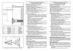
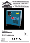
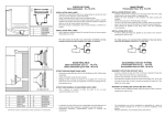
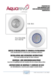
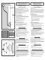
WARNING! DO NOT ATTEMPT TO USE
THESE LIGHTS OUT OF WATER
ATTENTION : NE PAS FAIRE FONCTIONNER
LES PROJECTEURS HORS DE L'EAU
Incandescent underwater light - serial 8145x
Projecteur Incandescence - série 8145x
CARACTERISTIQUES TECHNIQUES
Le projecteur doit éclairer dans le sens opposé à la maison ou à la terrasse
pour ne pas gêner par un éclairage trop violent.
Le projecteur doit être positionné à 60 cm. au maximum sous la margelle depuis
l'axe de l'ampoule. La niche du projecteur est pourvue de deux sorties 3/4". La
sortie arrière est généralement utilisée pour les piscines maçonnées et la sortie
verticale pour les piscines panneau.
300 W - 12 V - AC / Utiliser un transformateur de sécurité avec un
secondaire > ou égal à 300 VA sous 12 V
.
STRUCTURE MACONNÉE LINER
.
.
.
.
.
.
Sceller la niche du projecteur dans la maçonnerie. Finir l’enduit à fleur
de la face avant, en respectant l’orientation haute de la niche. Condamner la
sortie non utilisée avec le bouchon.
Poser le joint sur la face avant de la niche du projecteur.
Poser le joint sur la bride de la niche du projecteur.
Fixer la bride d'étanchéité après la pose du liner.
Découper le liner
STRUCTURE MACONNÉE SANS LINER
1
PWX240
2
PWX9513
3
PWX20008
4
PRX20005
5A+B PWXVS
6
PWX9472
7
PWX20020
8
8
9
10
11
12
PWX9470 (BETON)
PWX9471 (LINER)
PWX20021
PRX9120
PWX20007
PRX20018
.
.
.
.
.
Sceller la niche du projecteur dans la maçonnerie, la partie avant
en retrait pour la réalisation de l'enduit fini ou du carrelage.
Réaliser l’étanchéité de la gaine du cable, et la pose de l’optique
projecteur identique au projecteur liner.
Passer le cable de l'optique du projecteur à l’intérieur du presse étoupe.
Attention au positionnement de la garniture du presse étoupe.
Aiguiller le cable de l'optique du projecteur dans la gaine jusqu'à
la boite de connexion.
Réaliser l'étanchéité du cable avec le presse étoupe. Attention respecter le
positionnement de la garniture de ce presse étoupe. (l’extrémité avec angle
30° est positionnée en fond de corps de presse étoupe).
Présenter l'optique devant la niche en y enroulant le supplément
de cable.
Encastrer l'optique du projecteur dans la niche en postionnant
les griffes dans les stries.
Le remplacement de pièces doit être effectué avec des pièces d’origines.
Lors d’un changement d’ampoule et/ou du câble, il est préconisé de changer la
totalité des pièces assurant l’étanchéité. Type de lampe utilisé : PAR 56 en cas de
nécessité de changement de la lampe, utiliser la pièce d’origine.
Si le cordon d’alimentation ou la gaine est endommagé, il doit être remplacé par
le fabricant, un Centre Service Agréé ou un technicien qualifié afin d’éviter tout
accident.
BOITE DE CONNEXION (non fournie)
Informations indicatives, représentations “photos & schémas” non contractuelles.
Raccorder la gaine du projecteur à la sortie 3/4“ située sur le fond de la boîte
de connexion.
Les sorties des côtés permettant le passage des cables d’alimentation
électrique.
RACCORDEMENT DANS LA BOITE DE CONNEXION (non fournie)
Préconisation de raccordement : raccorder dans la boite de connexion (non fournie)
IPX5, l’extrémité du câble à l’alimentation venant du local technique, utiliser les blocs
de jonctions fournis avec les boites de connexion pour raccorder le projecteur à
l’alimentation en torsadant les fils et serrant bien les vis des bornes de jonctions.
Le fabricant ne pourra être tenu pour responsable d'un dommage direct
ou indirect provenant d'une utilisation ou installation incorrecte du produit.
Informations indicatives, représentations, photos et schémas
non contractuels.
.
.
.
LINER MASONRY STRUCTURE
.
.
.
.
.
Seal the projector’s niche into the masonry, making sure that you position
it the right way up. Fit the plug in the unused outlet. Take necessary steps
to ensure that you can subsequently apply rendering around the front
panel.
Fit the seal on the front panel of the projector’s niche.
Fit the seal on the flange of the projector’s niche.
Secure the sealing flange after installing the liner.
Cut the liner
MASONRY STRUCTURE WITHOUT LINER
.
Seal the niche of the projector into the masonry; the front part should be
recessed, so that finishing rendering or tiling can be applied
subsequently.
Proceed with sealing the flexible conduit and cable, and install the lighting
unit of the projector in the same way as for the vinyl light.
INSTALLATION DU PROJECTEUR
MAINTENANCE DU PRODUIT
.
.
TECHNICAL CHARACTERISTICS
Point the projector away from the house or terrace, so as not to create an
excessively bright illumination.
The projector should not be positioned more than 60 cm under the coping, as
measured from the centre of the bulb. The projector’s niche incorporates two 3/4’’
outlets. The rear outlet is generally used for masonry swimming pools, while the
vertical outlet is primarily intended for swimming pools built from panels.
300 W - 12 V - AC / Use a safety transformer with an output greater than or
equal to 300 VA at 12 V.
.
.
.
.
.
INSTALLATION OF INCANDESCENT LIGHT
Push the projector’s lighting unit cable through the cable gland. Warning,
respect the positioning of the gaskat of the bushing.
Thread the cable of the projector’s lighting unit through the
flexible conduit up to the connection box.
Seal the cable gland around the cable. Warning, respect the positioning of the
gasket of the bushing. (the end with angle 30° is positioned in bottom of body).
Place the lens in front of its housing rolling up any extra cable.
Fit the projector’s lighting unit into the niche, positioning the
claws within the striae.
PRODUCT MAINTENANCE
Original components must be used in all replacement operations.
When changing a bulb and/or cable, it is recommended that all components be
changed to avoid compromising the seals. Type of light used : PAR 56, in the
event of necessity changing of the light, to use original part.
If the external flexible cable or cord of this luminaire is damaged, it shall be
exclusively replaced by the manufacturer or his service agent or a similar qualified
person in order to avoid a hazard.
.
.
CONNECTION BOX (not provided)
Connect the light flexible conduit to the 3/4’’ outlet located on the
bottom of the connection box.
The outlets on the sides allow throughway for electrical power
cables.
CONNECTION WITHIN THE JUNCTION BOX (not provided)
Recommendation of connection : to connect in the junction box (not available)
IP X 5, the end of the cable for electrical power supply coming from the technical
box, use the connector blocks provided with the juction box to connect the
spotlight to the power supply by twisting the wires and ensuring that the terminal
screws are well tightened.
The manufacturer can not be considered as responsible for a direct or
indirect damage resulting from an use or an incorrect installation of the
product.
Indicative information, not contractual photos and schema.
.
.
ATENCION: NO ENCENDER LOS
PROYECTORES FUERA DEL AGUA
ACHTUNG : DIE SCHEINWERFER NICHT AUSSERHALB DES
WASSERS EINSCHALTEN
PROYECTOR INCANDESCENT- série 8145x
GLIMMER SCHEINWERFER 300 W - Serie 8145x
CARACTERISTICAS TECHNICAS
TECHNISCHE DATEN
El proyector debe iluminar en el sentido opuesto a la casa o terraza para no
deslumbrar.
El proyector debe situarse a 60 cm como máximo por debajo de la piedra de
coronación, desde el eje de la bombilla.EI nicho del proyector esta provisto
de dos salidas 3/4" .La salida de detrás se uliliza en piscinas de hormigón y
la salida vertical para piscinas en panel
300 W - 12 V - AC / Utiliza un transformador de seguridad con un
secundario > o igual a 300 VA y 12 V
Der Scheinwerfer soll in dem Haus oder der Terrasse gegen¸berliegender
Richtung leuchten, um keine Stürung durch zu starke Beleuchtung zu verursachen.
Der Scheinwerfer mußhöchstens 60 cm unter der Einfassung ab der
Glühbirnenachse angebracht werden. Die Nische des Scheinwerfers ist mit
zwei Ausgängen 3/4’’ ausgerüstet. Der rückseitige Ausgang wird im
allgemeinen für die gemauerten Schwimmbecken und der vertikale Ausgang
für die Platten-Schwimmbecken verwendet.
Technische daten : 300 W - 12 v - AC / Einen Sischerheitstransformator mit
einer Sekundärwicklung 300 VA / 12 V oder entsprechend benutzen
.
.
.
.
ESTRUCTURA CONSTRUIDA EN LINER
.
.
Sellar el nicho del proyector en el hormigon y tapar la salida inutilisada
Poner la junta en Ia parte delantera del nicho del proyector
Poner la junta en la brida del nicho del proyector
Fijar la brida de hermeticidad después de poner el liner
ESTRUCTURA CONSTRUIDA SIN LINER
.
.
.
.
.
Sellar el nicho del proyector en la construcción, la parte delantera
retraida parafinalmente embaldosar o revestir
Realizar la hermeticidad del cable de la funda y colocar del óptico del
proyector igual que con el proyector liner
INSTALACIÒN DEL PROYECTOR
Pasar el cable del óptico del proyector al interior de la prensa - estopa
Cuidado a la posición de la junta del prensa estopa.
Agujerear el cable del óptico del proyector en la funda hasta la
caja de conexiones
Realizar la hermeticidad del cable con el prensa-estopa Cuidado respe
tar la posición de la junta de este prensa estopa (la extremidad con angu
lo de 30° hay que ponerla en el fondo del alojamiento del cuerpo del pren
sa estopa).
Presentar el óptico antes del nicho enrollando en el mismo el
supplemento del cable
Empotrar el óptico del proyector en el nicho poniendo las grapas
en las ranuras
MANTENIMIENTO DEL PRODUCTO
El reemplazo de las piezas se debe efectuar con piezas originales.
Al cambiar una bombilla y/o un cable, se aconseja cambiar la totalidad de las
piezas que aseguran la estanqueidad. Tipo de làmpara utilizado : PAR 56. En
caso de necesidad de cambio de la làmpara, utilizar la parte de origen.
Si el cable de alimentación está dañado, debe ser sustituido por Hayward o
por un centro de servicio autorizado por Philips, con el fin de evitar
situaciones de peligro.
.
.
.
.
.
.
.
.
Empalmar la funda del proyector a la salida de 3/4" situada en la parte
inferior de la caja de conexiones
Las salidas laterales permiten el paso de los cables de alimentación
eléctrica
El fabricante no puede ser considerado como responsable de un
daño directo o indirecto que es resultado de un empleo o una instalación
incorrecta del producto.
Información indicativa, no esquera contractual.
Die Nische des Scheinwerfers im Mauerwerk verankern. Den Verputz
bündig mit der Vorderseite abschlie(en unter Beachtung der oberen
Ausrichtung der Nische. Den nicht verwendeten Ausgang mit dem
Stopfen verschließen.
Die Dichtung an der Vorderseite der Scheinwerfernische anbringen.
Die Dichtung am Flansch der Scheinwerfernische anbringen.
Den Dichtungsflansch nach Verlegung des Liners befestigen.
PROJECTEUR INCANDESCENT
INCANDESCENT UNDERWATER LIGHT
PROYECTOR INCANDESCENTE
UNTERWASSER SCHEINWERFER
MAUERSTRUKTUR OHNE LINER
.
.
.
.
.
Die Scheinwerfernische im Mauerwerk verankern, den vorderen Teil
nach hinten versetzt, für den Fertigverputz oder die Fliesenverlegung.
Die Dichtheit der Kabelschutzrohr und des Kabels herstellen und
die Scheinwerferoptik wie beim Liner-Scheinwerfer anbringen.
EINRICHTUNG GLIMMER SCHEINWERFER
Das Kabel der Scheinwerferoptik durch die Stopfbuchse führen.
Beachtung an der lokalisierung der garnitur der presse stopft zu.
Das Kabel der Scheinwerferoptik durch die Kabelschutzrohr biszum
Anschlußkasten führen.
Die Dichtheit des Kabels mit der Stopfbuchse herstellen.
Wollen sie bitte es darauf achten.
Beachtung die lokalisierung der garnitur preßt zu respektieren von dieses
werg (ende mit 30° winkel ist in grund der pressekörper werg lokalisiert).
Die Scheinwerferoptik vor die Nische bringen, dort zu viel Kabel aufrollen
Die Optik des Scheinwerfers durch Positionieren der Klauen in die Rillen
in die Nische setzen.
PRODUKTINSTANDHALTUNG
Zum Austauschen Originalteile benutzen.Beim Wechsel einer Glühbirne
und/oder des Kabels wird das Austauschen aller Dichtungsteile empfohlen.
Benutzter lampentyp: PAR 56 bei der lampe das ursprungsstück zu benutzen.
Zur Vermeidung von Gefährdungen darf eine beschädigte äußere flexible
Leitung dieser Leuchte ausschließlich vom Hersteller, seinem Servicevertreter
oder einer vergleichbaren Fachkraft ausgetauscht werden.
CAJA DE CONEXIONES (no proporcionado)
CONEXION EN LA CAJA DE CONEXION (no proporcionado)
Recomendaciòn de conexiòn : conectar en la caja de connexion ( no
proporcionado)IP X 5, l’extremidad del cable a la alimentaciòn que viene del
local tècnico. Utilizar los bloques de uniones suministrados con las cajas de
conexiòn para conectar el proyector a la alimentaciòn, torciendo los cables y
apretando bien los tornillos de los bornes de uniòn.
.
.
MAUERSTRUKTUR LINER
IS81450 - REV A - 07
.
.
ANSCHLUSSKASTEN (nicht geliefert)
Die Kabelschutzrohr des Scheinwerfers am Ausgang 3/4’’ am Boden des
Anschlußkastens anschließen.
Die seitlichen Ausgänge ermüglichen die Durchführung der
tromversorgungskabel.
ANSCHLIESSEN IM KABELVERBINDUNGSKASTEN (nicht geliefert)
Verbindungspräkonisation : zu verbinden in hinkt es von Verbindung (nicht
geliefert) Ip X5, extremite vom kabel an der Ernährung, das vom technischen
raum kommt. Zum Anschließen des Scheinwerfers an die Stromversorgung
die mit dem Anschlusskasten gelieferten Reihenklemmen benutzen, wobei
die Drähte verdrillt und die Schrauben der Lüsterklemmen gut
festgezogen werden.
Der Erzeuger wird keinen Verantwortlichen für eines direkten oder
indirekten Schadens gehalten sein können, der aus einer Benutzung
oder einer inkorrekten Einrichtung des Produktes verbindet.
Zum Info, nicht vertragliche Fotos und Schemas.
NOTICE D’UTILISATION
USER’S GUIDE
GUIA DEL USUARIO
ANWENDER HANDBUCH
.
.
HAYWARD POOL EUROPE
- P.I.P.A. - Allée des Chênes - 01150 Saint Vulbas - France