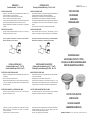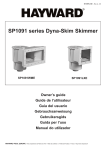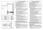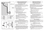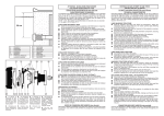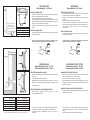
1
PIECES DE FOND
Débit admissible : 5 à 15 m3/h
4
1
4
2
3
Au niveau le plus bas de la piscine
In the lowest part of the pool
En la parte mas baja de la piscina
Auf den niedrigsten Teil des Bekens
INSTALLATION SANS LINER
.
.
.
.
1
2
3
4
PDFX9958
PDFX9959
PDFX20050
PDFXVS
Raccorder un tuyau Ø50 ou Ø63 sur la sortie latérale de la pièce de fond
avec les raccords adéquats et faire l’étanchéité.
Placer l’ensemble dans le radier avant le coulage du béton.
Positionner la pièce de fond dans la partie la plus basse du bassin. La partie
supérieure de la pièce de fond devra être maintenue pendant le coulage du
béton au nu fini du niveau intérieur de la piscine.
Raccorder ensuite la canalisation, dans le local technique, à l’entrée de la
pompe
INSTALLATION AVEC LINER
.
Idem ci-dessus en ajoutant la bride (2), les joints (3) et les vis (4) pour assurer
l’étanchéité avec le liner.
MAIN DRAINS
Permissible flow: 5 to 15 m3/h
INSTALLATION WITHOUT VINYL
.
.
.
.
.
Connect a diameter 50 or 63 pipe to the side outlet of the main drain, using
suitable unions, and ensure there is a waterproff seal.
Position the entire assembly in the foundation raft before pouring the
concrete.
Position the main drain in the lowest part of the pool.
The top of the main drain should be held in position when the concrete is
poured, so that it is level with the bottom of the swimming pool afterwards.
Then connect the pipeline to the pump inlet in the pool equipment
room/house/bay.
INSTALLATION WITH VINYL
.
Pour des raisons de sécurité, nous préconisons l’installation de deux
bondes de fond devant êtres distantes d’un mètre au minimum.
As above, adding the flange (2), gaskets (3), and screws (4) to ensure a
waterproof join with the vinyl.
For safety reasons, we recommend the installation of two main drains.
They must be installed a minimum of 1 meter apart.
6
4
3
2
BUSE REGLABLE
Débit admissible pour 2” : 10 m3/h
Débit admissible pour D90 : 40 m3/h
1
STRUCTURE MACONNEE SANS LINER
13
.
.
.
30 cm
12 “
Raccorder un tuyau Ø63 (pour 3318 / 3319) et Ø90 (pour 3302 / 3303) et faire
l’étanchéité.
Sceller l’ensemble en pied de paroi verticale.
Réglage du débit : Dévisser en partie les vis des grilles (3+4 / 9+10) et les
faire tourner l’une sur l’autre pour augmenter ou diminuer le passage de l’eau.
Puis resserrer les vis.
STRUCTURE PANNEAU OU MACONNEE AVEC LINER
12
1
2
3
4
6
7
BR2X9953
BR2X20022
BR2X10258
BR2X10257
BR2XVS
BR3X10223
8
9
10
14
11
13
11 10
9
8
14
7
BR3X22101
BR3X9946
BR3X9945
BR3X22090
BR3X22105
BR3XVS
Informations indicatives, représentations “photos & schémas” non contractuelles.
.
.
.
Idem ci-dessus en ajoutant la bride, les joints et les vis pour
assurerl’étanchéité avec le liner.
Le fabricant ne pourra être tenu pour responsable d'un dommage direct ou
indirect provenant d'une utilisation ou installation incorrecte du produit.
Informations indicatives, représentations, photos et schémas non
contractuels.
ADJUSTABLE OUTLET FITTING
Permissible flow for 2” : 10 m3/h
Permissible flow for D90 : 40 m3/h
MASONRY STRUCTURE WITHOUT VINYL
.
.
.
Connect a diameter 63 pipe (for 3318 / 3319) and a diameter 90 pipe (for
3302 / 3303), and ensure there is a waterproof seal.
Seal the entire assembly at the foot of the vertical wall.
Flow adjustment: partially unscrew the screws of the grates (3+4 / 9+10), and
turn them on each other in order to increase or decrease the water flow. Then
tighten the screws again.
MASONRY OR PANELLING STRUCTURE WITH VINYL
.
.
.
Proceed as above, adding the flange, seals and screws in order to ensure a
waterproof join with the vinyl.
The manufacturer can not be considered as responsible for a direct or
indirect damage resulting from an use or an incorrect installation of the
product.
Indicative information, not contractual photos and schema.
SUMIDEROS
Caudal admisible : 5 a 15 m3/h
INSTALACION SIN LINER
.
.
.
.
.
Empalmar un tubo de Ø50 ó Ø63 en la salida lateral del sumidero con los
racores adecuados y hacer la hermeticidad.
Situar el conjunto en el fondo antes de poner el hormigón.
Poner el sumidero en la parte más baja de la piscina.
La parte superior del sumidero tendrá que ser mantenida durante la colada
del hormigon para quedarse despues al nivel interior de la piscina.
Empalmar seguidamente la canalización, en el local técnico, a la entrada de
la bomba.
INSTALACION CON LINER
.
Igual que lo anterior añadiendo la brida (2), las juntas (3) y los tornillos (4)
para asegurar la estanquida con el liner.
BODENABLAÜFE
Zuùssige Durchsatzleistung : 5 bis 15 m3/h
INSTALLATION OHNE LINER
.
.
.
.
.
.
Empalmar un tubo Ø63 (para 3318 / 3319) y Ø90 (para 3302 / 3303) y hacer
la estanquida.
Selar el conjunto al pie del tabique vertical.
Regulación del caudal: desenroscar un poco los tornillos de las rejillas (3+4
/ 9+10) y girar las rejillas para aumentar o disminuir el paso del agua. Apretar
de nuevo los tornillos.
ESTRUCTURA EN PANEL O CONSTRUIDA EN LINER
.
Igual que lo anterior añadiendo la brida, las juntas y los tornillos para
asegurar la estanquida con el liner.
SUMIDEROS
BODENABLAÜFE
Siehe vorstehend, jedoch den Flansch (2), die Dichtungen (3) und die
Schrauben (4) hinzufügen, um die Dichtheit mit dem Liner zu gewährleisten.
Zur Sicherheit, empfehlen wir die Einrichtung von zwei Bodenablaüfe.
Beide müssen ein Minimum von 1 Meter miteinander entfernt.
BOQUILLA REGULABLE
Caudal admisible para 2” : 10 m3/h
Caudal admisible para D90 : 40 m3/h
.
.
.
PIECE DE FOND
MAIN DRAINS
INSTALLATION MIT LINER
Para su seguridad, recomendamos la instalación de dos sumideros.
Deben ser separados de 1 metro mínimo.
ESTRUCTURA CONSTRUIDA SIN LINER
Einen Schlauch (50 oder 63 an den seitlichen Ausgang des Bodenablaüfe mit
geeigneten Stutzen anschließen und die Dichtheit herstellen.
Die Baugruppe auf die Sohle setzen, bevor der Beton gegossen wird.
Das Bodenablaüfe auf den niedrigsten Teil des Beckens positionieren.
Das Oberteil des Bodenablaüfe muß während des Gießens des Betons auf
der fertiggestellen internen Ebene des Schwimmbeckens festgehalten
werden.
Dann die Leitung im Technikraum am Pumpeneingang anschließen.
BRNOTICE - REV C - 07
EINSTELLBARE EINLAUFDÜSE
Zulässige Durchsatzleistung für 2” : 10 m3/h
Zulässige Durchsatzleistung für Ø90 : 40 m3/h
BUSE REGLABLE
ADJUSTABLE OUTLET FITTING
BOQUILLA DE IMPULSION REGULABLE
EINSTELLBARE EINLAUFDÜSE
MAUERSTRUKTUR OHNE LINER
.
.
.
Einen Schlauch Ø63 (für 3318 / 3319) und Ø90 (für 3302 / 3303) anschließen
und die Dichtheit herstellen.
Die Baugruppe am Fuß der vertikalen Wand verankern.
Einstellung der Durchsatzleistung : Die Schrauben der Gitter (3+4 / 9+10)
teilweise losdrehen und sie gegeneinander drehen, um den Wasserdurchlauf
zu vergrößern oder zu verringern. Die Schrauben dann wieder festdrehen.
PLATTEN ODER MAUERSTRUKTUR MIT LINER
.
Wie vorstehend, jedoch den Flansh, die Dichtungen und die Schrauben
hinzufügen, um die Dichtheit mit dem Liner zu gewährleisten.
NOTICE D’UTILISATION
USER’S GUIDE
GUIA DEL USUARIO
.
.
El fabricante no puede ser considerado como responsable de un daño
directo o indirecto que es resultado de un empleo o una instalación
incorrecta del producto.
Información indicativa, no esquera contractual.
.
.
Der Erzeuger wird keinen Verantwortlichen für eines direkten oder indirekten
Schadens gehalten sein können, der aus einer Benutzung oder einer
inkorrekten Einrichtung des Produktes verbindet.
Zum Info, nicht vertragliche Fotos und Schemas.
ANWENDER HANDBUCH
HAYWARD POOL EUROPE
- P.I.P.A. - Allée des Chênes - 01150 Saint Vulbas - France