1
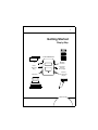
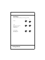
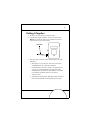
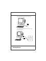
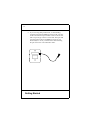
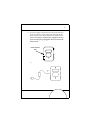
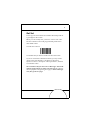
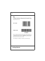
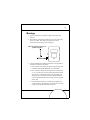
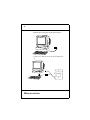
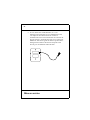
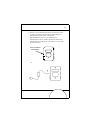
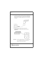
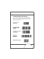
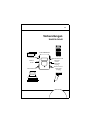
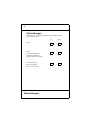
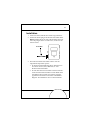
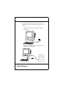
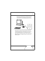
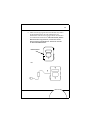
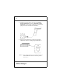
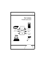
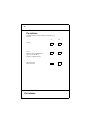
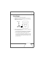
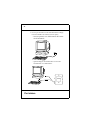
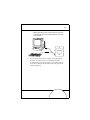
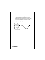
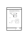
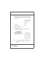
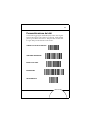
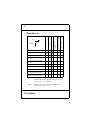
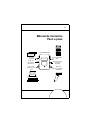
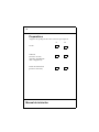
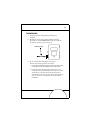
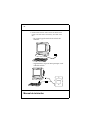
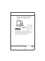
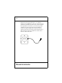
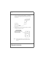
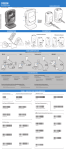
RS 2200/3200 LLSeries 500 Quick Reference • Guide utilisateur • Kurzübersicht • Guida rapida • Guía rapida • Quick Reference • Guide utilisateur • Kurzübersicht • Guida rapida • Guía rapida • Quick Reference • Guide utilisateur • Kurzübersicht • Guida rapida • Guía rapida • Quick Reference • Guide utilisateur • Kurzübersicht • Guida rapida • Guía rapida • Quick Reference • Guide utilisateur • Kurzübersicht • Guida rapida • Guía rapida • Quick Reference • Guide utilisateur • Kurzübersicht • Guida rapida • Guía rapida • Quick Reference • Guide utilisateur • Kurzübersicht • Guida rapida • Guía rapida • Quick Reference • Guide utilisateur • Kurzübersicht • Guida rapida • Guía rapida • Quick Reference • Guide utilisateur • Kurzübersicht • Guida rapida • Guía rapida • Quick Reference • Guide utilisateur • Kurzübersicht • Guida rapida • Guía rapida • Quick Reference • Guide utilisateur • Kurzübersicht • Guida rapida • Guía rapida • Quick Reference • Guide utilisateur • Kurzübersicht • Guida rapida • Guía rapida • Quick Reference • Guide utilisateur • Kurzübersicht • Guida rapida • Guía rapida • Quick Reference • Guide utilisateur • Kurzübersicht • Guida rapida • Guía rapida • Quick Reference • Guide utilisateur • Kurzübersicht • Guida rapida • Guía rapida • Quick Reference • Guide utilisateur • Kurzübersicht • Guida rapida • Guía rapida • Quick Reference • Guide utilisateur • Kurzübersicht • Guida rapida • Guía rapida • Quick Reference • Guide utilisateur • Kurzübersicht • Guida rapida Getting Started 1997 - 2000 SYMBOL TECHNOLOGIES, INC. All rights reserved. Symbol reserves the right to make changes to any product to improve reliability, function, or design. Symbol does not assume any product liability arising out of, or in connection with, the application or use of any product, circuit, or application described herein. No license is granted, either expressly or by implication, estoppel, or otherwise under any patent right or patent, covering or relating to any combination, system, apparatus, machine, material, method, or process in which Symbol products might be used. An implied license only exists for equipment, circuits, and subsystems contained in Symbol products. Symbol and the Symbol logo are registered trademarks of Symbol Technologies, Inc. Other product names mentioned in this manual may be trademarks or registered trademarks of their respective companies and are hereby acknowledged. Symbol Technologies, Inc. One Symbol Plaza Holtsville, N.Y. 11742-1300 Getting Started 1 Getting Started Step by Step LL 500 OMNILINK Magstripe Port Power Selection Plug Host Port RS-232C Aux Port Secondary Scanner Port (9-pin) Primary Scanner Port (15-pin) 2 Get Ready Be sure you have everything you need to get started. Yes LL 500 Cable (At least one, maybe two, depending on your configuration) Power Supply (You may or may not need this) Getting Started No 3 Putting It Together 1. Be sure your host device is powered down. 2. Connect the 40-pin connector on the host cable to the HOST port on the LL 500. If your cable doesn’t have a 40-pin connector, proceed to step 5. Host Cable 3. The other end of the host cable should match one of the following: • The input port on your host. This may be an OCIA, OCR, IBM 468x/9x, or RS-232C terminal. • A POS Internal connection. In this case you’ll have to open up your POS terminal and connect the cable internally. This procedure is described for some of the most popular terminals in the LL 500 Product Reference Guide. • A keyboard wedge. The LL 500 is physically connected between the terminal and the keyboard. To do this: 4 - First, unplug the keyboard at the terminal end. - Next, attach one end of the host cable to the end of the keyboard cable. Getting Started 5 - Finally, attach the remaining connector on the host cable to the receptacle on the host terminal where the keyboard was originally connected. 4. If your host cable attaches to an RS-232C device, the LL 500 Product Reference Guide defines the pin-outs for the various RS-232C cables. If you are not connecting another device to the AUX port, go to step 6. 6 5. If you are using dual-port RS-232C, or downloading parameters through the AUX port of the LL 500, you have a cable which has an 8-pin modular connector at one end, and a 25-pin d-type connector at the other. The 8-pin end gets plugged into the LL 500 AUX port. In the LL 500 Product Reference Guide you’ll find some tables defining the pin-outs for the various RS-232C cables. Getting Started 7 6. If a power supply is required, remove the power selection plug and connect a power supply to that receptacle. The power supply must comply with all local regulations. If you are not using an external power supply, be sure the power selection plug is plugged in. If it is not, the LL 500 will not work. Power Selection Plug or Power Supply 8 7. Attach a scanner to either the Primary Scanner Port, or the Secondary Scanner Port. The connector at the end of the scanner’s cord will fit in only one of those ports. 8. If you want to use a magstripe reader, plug it into the Magstripe Port. Magstripe Port Note: Some configurations (i.e., LL-500-I20X-170Y and LL500-I20X-80Y) only support the Primary Scanner Port. Getting Started 9 Get Set Power-up your host terminal. You will hear three beeps and see a green light on the LL 500. Before you can actually start, you have to scan two bar codes. The bar code below will set all programmable parameters to their default values. Scan this bar code now. You should have just heard a warble tone from the LL 500. If you are connected to a RS-232C terminal, you may need to change some of the defaults. Consult the LL 500 Product Reference Guide for a description of those parameters, and their associated bar codes. The second bar code you must scan is a Host Type. The LL 500 will not operate unless you select your host type. Bar codes for the most popular host types begin on page 71. Scan a Host Type now, then go the next page. 10 Go To ensure everything is working as it should, scan the test bar codes below. For each successful decode, you will hear a single beep from the LL 500. UPC-A TEST CODE 39 TEST If you could not decode these bar codes, or if the LL 500 is not working properly at this point, see What If... on page 12. If you can’t find the problem, call our Support Center at the number listed in your Product Reference Guide. If everything is working as it should, go to the next page. Getting Started 11 Customizing the Data If you want to append an ENTER (CR) to all data, scan the five bar codes below, starting at the top and working down. When you do this, all previously stored ADF rules will be deleted. ERASE ALL RULES ANY SOURCE SEND ALL DATA SEND ENTER SAVE RULE 12 Proper configuration?* X X Position of J2/J4** No decode X Magstripe inoperative X Scanner inoperative Plugged into correct port? Wrong data or garbled Check No transmit If No power up What If... X X X X X X Correct Host Type programmed? X Correct parameters selected? X X Power to host system? X X Cable connected to host? X X Power selection plug inserted? X X X X X Power supply plugged in? X X X Reset controller (push reset button, hold 2 seconds) X X X X X Note: *Some configurations do not decode UPC or Code 39. Try decoding a bar code specific to your application. Note: **See the User’s Guide portion of the LL 500 Product Reference Guide. Getting Started 13 A look at the individual components. LL 500 This is the interface controller that lets you take bar code, magstripe and/or serial data and send it to your host system. You’ll notice the various ports and connectors and LEDs. There’s a description of each of them in the LL 500 Product Reference Guide. Pay special attention to the Power Selection Plug. If this plug is removed, and an external power supply is not connected, the unit will not operate. Depending on the model of LL 500, the Primary and Secondary scanner ports have been pre-set for 5V or 12V scanners. LL 500-I200 models have the primary port configured for 12V, and the secondary port for 5V. LL 500-I201 models have the primary port configured for 5V, and the secondary port for 12V. Cable Every unit needs one (or more). This is the physical connection between the LL 500 and your host device. You may have two cables because some interfaces (like dual port RS-232-C) require two. Power Supply Some host devices supply enough power to run the LL 500 and its attached scanner. When that’s not the case, you’ll need an external power supply. If you’re not sure if your host supplies sufficient power, ask your Symbol representative. 14 What Does The Beep Mean? When you hear 1 beep (short high tone) it means data has been decoded successfully. If any other beeps are heard, contact the technical person in charge of scanning. A Closing Word We hope this guide has helped you become familiar with your LL 500. For an in depth look at this controller consult the LL 500 Product Reference Guide and Advanced Programmer’s Guide. Getting Started 15 Mise en service LL 500 OMNILINK (interface universelle) Port lecteur de cartes magnétiques Fiche de sélection d'alimentation Port pour le système central Port auxiliaire RS-232C Port pour second lecteur (9 broches) Port pour premier lecteur (15 broches) 16 Préparation Assurez-vous que vous disposez de tout ce qu'il vous faut avant de commencer. Oui LL 500 Câble (au moins un, peut-être deux selon votre configuration) Alimentation électrique (si nécessaire) Mise en service Non 17 Montage 1. Assurez-vous que le système récepteur n'est pas sous tension. 2. Raccordez le connecteur à 40 broches au port du LL 500 prévu à cet effet. Si le câble n'est pas pourvu d'un connecteur 40 broches, passez à l'étape 5. Câble de communication vers le système récepteur 3. L'autre extrémité du câble 40 points doit correspondre à l'une des connexions suivantes : • Port d'entrée du système récepteur. Il peut s'agir d'un terminal OCIA, OCR, IBM 468x/9x ou RS-232C. • Une connexion interne terminal point de vente. Dans ce cas, vous devrez ouvrir le boîtier du terminal point de vente et y connecter le câble. Cette procédure est décrite pour les terminaux les plus répandus dans la section Guide d'interface du Guide de référence produit du LL 500. • Une émulation clavier. Le LL 500 est physiquement connecté entre le terminal et le clavier. Pour le raccordement, procédez de la manière suivante: 18 - Débranchez d'abord le clavier du terminal. - Connectez ce câble clavier à l'une des extrémités du "Y." Mise en service 19 - L'autre extrémité du "Y" vient se connecter sur le système récepteur en lieu et place du câble clavier. 4. Si le câble 40 points du LL 500 est raccordé à un système récepteur RS-232C, le Guide de référence produit du LL 500 définit le brochage pour les différents câbles RS-232C. Si vous ne raccordez pas d'autre périphérique au port AUX, passer à l'étape 6. 20 5. Si vous utilisez une double RS-232C, ou si vous téléchargez des paramètres via le port AUX du LL 500, vous disposez d'un câble muni d'un connecteur modulaire 8 broches à une extrémité et d'un connecteur 25 broches à l'autre. L'extrémité 8 broches se raccorde au port AUX du LL 500. Dans le guide de référence produit du LL 500 figurent des tableaux décrivant la disposition des broches pour les différents câbles RS-232C. Mise en service 21 6. Dans le cas où l'alimentation externe est nécessaire, celleci vient se connecter à la place de la fiche de sélection d'alimentation qui doit être conforme aux réglementations locales. Si vous n'utilisez pas d'alimentation externe, vérifiez que la fiche de sélection d'alimentation est enfichée. Si ce n'est pas le cas, le LL 500 ne fonctionne pas. Fiche de sélection d'alimentation ou Alimentation secteur 22 7. Vous pouvez connecter un lecteur sur le port primaire (15 pts) ou secondaire (9 pts). Le connecteur à l'extrémité du câble du lecteur s'adapte uniquement à l'un ou l'autre de ces 2 ports. 8. Si vous souhaitez utiliser un lecteur de cartes magnétiques, raccordez-le au port lecteur de cartes magnétiques. Port lecteur de cartes magnétiques Remarque : certaines configurations (par ex., LL-500-I20X-170Y et LL-500-I20X-80Y) prennent uniquement en charge le port de lecteur primaire.). Mise en service 23 Mise en route Mettez l'ordinateur central en marche. Trois bips sonores retentissent et un témoin vert s'allume sur le LL 500. Avant de commencer, il faut lire deux codes à barres. Le code cidessous règle tous les paramètres programmables sur leurs valeurs par défaut. A présent, lisez ce code. Le LL 500 émet un bip modulé. Si vous êtes raccordé à un terminal RS-232C, il est peut-être nécessaire de modifier certaines valeurs par défaut. Consultez le Guide de référence produit du LL 500 pour obtenir une description de ces paramètres et des codes à barres correspondants. Le deuxième code à barres que vous devez lire définit le type d'ordinateur central. Le LL 500 ne fonctionne que lorsque ce dernier est sélectionné. Les codes à barres des ordinateurs centraux les plus répandus sont indiqués à partir de la page 71. Sélectionnez un type d'ordinateur central maintenant, puis passez à la page suivante. 24 Mise en oeuvre Pour vérifier que tout fonctionne normalement, lisez les codes à barres de test ci-dessous. Pour chaque décodage réussi, le LL 500 émet un seul bip. TEST UPC-A TEST CODE 39 Si vous ne parvenez pas à décoder ces codes ou si le LL 500 ne fonctionne pas correctement, reportez-vous aux instructions de dépannage page 26. Si vous ne parvenez pas à identifier le problème, contactez votre centre de support technique. Si tout fonctionne normalement, passez à la page suivante. Mise en service 25 Personnalisation des données Si vous souhaitez ajouter un retour chariot (CR) à toutes les données, lisez successivement les cinq codes à barres ci-dessous de haut en bas. Cette opération effacera toutes les règles ADF enregistrées précédemment. EFFACER TOUTES LES REGLES PROVENANCE DES DONNEES : TOUTES SOURCES TRANSMETTRE TOUTES LES DONNEES ENVOI DE LA VALIDATION : ENTREE (CR) ENREGISTRER LA REGLE 26 Raccordement effectué sur le bon port ? Configuration correct ?* X X X Le type de système récepteur programmé est-il correct ? X Les paramètres sélectionnés sont-ils corrects ? X X X X X Le système récepteur est-il sous tension ? X X Le câble est-il raccordé au système récepteur ? X X La fiche de sélection d'alimentation estelle insérée ? Réinitialiser le contrôleur (presser et maintenir la touche de réinitialisation enfoncée pendant 2 secondes). X X Position J2/J4** L'appareil est-il sous tension ? Lecteur de carte magnétique hors service Pas de décodage X Lecteur hors service X Données erronées ou confuses Vérifiez Pas de transmission Si Pas de mise sous tension Dépannage X X X X X X X X X X X X X Note: * Certaines configurations personnalisées ne décodent pas UPC ou le code 39. Essayez de décoder un code à barres spécifique à votre application. Note: ** Consultez le Guide de référence produit du LL 500. Mise en service 27 Les différents composants LL 500 C'est une interface universelle permettant de lire des codes à barres, des pistes magnétiques, des données provenant d'un périphérique RS-232, et de les transmettre au système récepteur. Chacun des ports de communication, des connecteurs ou des LED est décrit à partir de la page 3 de la section Guide utilisateur du Guide de référence produit du LL 500. Soyez particulièrement attentif à la fiche de sélection d'alimentation. Si cette dernière est retirée et qu'aucune alimentation externe n'est raccordée, l'unité ne fonctionne pas. En fonction du modèle de LL 500, les ports primaire et secondaire ont été préréglés pour des lecteurs 5V ou 12V. Le port primaire des modèles LL 500-I200 est configuré sur 12V et le secondaire sur 5V. Le port primaire des modèles LL 500-I201 est configuré sur 5V et le secondaire sur 12V. Câble Chaque unité utilise un (ou plusieurs) câbles. Ils assurent le raccordement physique entre le LL 500 et le système récepteur. Il se peut qu'il y ait deux câbles dans le cas de certaines interfaces (par exemple : les doubles RS-232C). Alimentation Certains systèmes centraux disposent d'assez d'énergie pour alimenter le LL 500 et son lecteur. Si cela n'est pas le cas, il faut une alimentation externe. En cas de doute, contactez votre représentant Symbol. 28 Signification du bip sonore Lorsque vous entendez un bip (bref son aigu), les données ont été correctement décodées. Si vous entendez d'autres bips, contactez le technicien chargé de la maintenance. Conclusion Nous espérons que ce guide vous a permis de vous familiariser avec votre LL 500. Pour des informations plus précises sur ce contrôleur, consultez le Guide de référence produit du LL 500 et le Guide de programmation approfondie. Mise en service 29 Vorbereitungen Schritt für Schritt LL 500 OMNILINK MagstripeSchnittstelle Brückenstecker Host-Schnittstelle RS-232C AUX-Schnittstelle Sekundäre ScannerSchnittstelle (9-polig) Primäre ScannerSchnittstelle (15-polig) 30 Vorbereitungen Überprüfen Sie, ob alle erforderlichen Komponenten für den Start vorhanden sind. Ja LL 500 Kabel (je nach Konfiguration mindestens ein Kabel gegebenenfalls zwei Kabel) Stromversorgung (kann erforderlich sein oder auch nicht) Vorbereitungun Nein 31 Installation 1. Achten Sie darauf, daß Ihr Host-Gerät ausgeschaltet ist. 2. Stecken Sie den 40-poligen Stecker des Host-Kabels in die HOST-Schnittstelle des LL 500. Sollte Ihr Kabel nicht mit einem 40-poligen Stecker versehen sein, machen Sie mit Schritt 5 weiter. Host-Kabel 3. Das andere Ende des Host-Kabels sollte in eine der folgenden Komponenten passen: • In die Input-Schnittstelle Ihres Hosts. Dabei kann es sich um ein OCIA-, OCR-, IBM 468x/9x- oder RS-232C-Terminal handeln. • In einen POS-internen Anschluß. In diesem Fall müssen Sie Ihr POS-Terminal öffnen und das Kabel intern anschließen. Dieses Verfah–ren wird für einige der populärsten Terminals im Abschnitt "SchnittstellenRatgeber" des Handbuchs zum LL 500 beschrieben. 32 • In eine Tastaturweiche. Der LL 500 wird zwischen Terminal und Tastatur installiert. Dazu gehen Sie wie folgt vor: - Trennen Sie die Tastatur von der Computer- rückwand. - Schließen Sie nun ein Ende des Host-Kabels an ein Ende des Tastaturkabels an. Vorbereitungun 33 - Stecken Sie abschließend den verbleibenden Stecker des Host-Kabels in den Eingang des Host-Terminals, an dem zuvor die Tastatur angeschlossen war. 4. Soll Ihr Kabel an ein Gerät mit einer RS-232C-Schnittstelle angeschlossen werden, lesen Sie hierzu den Abschnitt "Schnittstellen-Ratgeber" des Handbuchs zum LL 500, in dem die Stiftbelegungen der verschiedenen RS-232CKabel definiert sind. Wenn Sie kein weiteres Gerät an die AUX-Schnittstelle anschließen möchten, machen Sie mit Schritt 6 weiter. 34 5. Falls Sie mit einer Doppelschnittstellen-RS-232C arbeiten oder Parameter über die AUX-Schnittstelle des LL 500 laden, steht Ihnen ein Kabel mit einem 8-poligen modularen Verbinder an einem Ende - und einem 25-poligen D-TypVerbinder am anderen Ende - zur Verfügung. Das 8-polige Ende wird in die AUX-Schnittstelle des LL 500 gesteckt. Der Produktleitfaden zum LL 500 enthält Tabellen, in denen die Stiftausgänge für die verschiedenen RS-232C-Kabel definiert sind. Vorbereitungun 35 6. Sollte eine Versorgung mit Strom erforderlich sein, ziehen Sie den Brückenstecker ab und schließen dort ein Netzkabel an. Die Netzversorgung muß mit den örtlichen Vorschriften übereinstimmen. Achten Sie darauf, daß der Brückenstecker eingesteckt ist, wenn keine externe Netzversorgung erforderlich ist. Ansonsten wird der LL 500 nicht funktionieren. Brückenstecker oder Netzversorgung 36 7. Schließen Sie einen Scanner entweder an die Primäre Scanner-Schnittstelle oder an die Sekundäre ScannerSchnittstelle an. Der Stekker am Ende der Scannerleitung paßt genau in eine der beiden Schnittstellen.* 8. Wenn Sie einen Magstripe-Leser benutzen möchten, schließen Sie diesen an die Magstripe-Schnittstelle an. MagstripeSchnittstelle Hinweis: Einige Konfigurationen (wie LL-500-I20X-170Y und LL-500-I20X-80Y) unterstützen nur den primären Scanner-Port. Vorbereitungun 37 Inbetriebnahme Schalten Sie Ihr Host-Terminal ein. Sie werden drei Pieptöne hören, und eine grünes Licht leuchtet am LL 500 auf. Vor dem eigentlichen Start müssen Sie noch zwei Strichcodes scannen. Der nachfolgende Strichcode stellt alle programmierbaren Parameter auf Ihre Standardwerte ein. Scannen Sie nun diesen Strichcode. Der LL 500 sollte einen schwankenden Ton von sich geben. Falls er an ein RS-232C-Terminal angeschlossen ist, müssen Sie unter Umständen einige der Standardwerte ändern. Das Handbuch zum LL 500 enthält Beschreibungen zu diesen Parametern und die entsprechenden Strichcodes. Beim zweiten Strichcode, den Sie scannen müssen, handelt es sich um den Host-Typ. Der LL 500 funktioniert nur nach erfolgter Auswahl Ihres Host-Typs. Die Codes der verbreitetsten Host-Typen sind ab Seite 71 aufgeführt. Scannen Sie nun einen Host-Typ ein, und gehen Sie zur nächsten Seite. 38 Start Damit Sie sicher sein können, daß alles vorschriftsmäßig funktioniert, sollten Sie die nachfolgenden Test-Strichcodes scannen. Nach jedem erfolgreichen Scannen gibt der LL 500 einen einzelnen Piepton von sich. UPC-A TEST CODE 39 TEST Sollte es nicht gelungen sein, diese Strichcodes zu scannen oder sofern der LL 500 nicht ordnungsgemäß arbeitet, wenden Sie sich dem Abschnitt "Was tun, falls ..." auf Seite 40 zu. Sofern das Problem auch weiterhin besteht, wenden Sie sich bitte telefonisch an den Kundendienst unter der Nummer, die in Ihrem Handbuch angegeben ist. Sobald alles ordnungsgemäß funktioniert, gehen Sie zur nächsten Seite. Vorbereitungun 39 Kundenspezifisches Anpassen der Daten Sofern Sie alle Daten durch ein ENTER (CR) ergänzen möchten, scannen Sie die nachfolgenden fünf Strichcodes der Reihe nach - von oben beginnend - ein. Dabei werden alle vorher gespeicherten ADF-Festlegungen gelöscht. ALLE FESTLEGUNGEN LÖSCHEN BELIEBIGE QUELLE ALLE DATEN SENDEN ENTER SENDEN FESTLEGUNGEN SPEICHERN 40 X X Config korrekt?* X Position von J2/J4** X Richtige Parameter gewählt? X X X X X X Host-System mit Strom versorgt? X X Kabel an Host angeschlossen? X X Brückenstecker eingesteckt? Controller neu booten. (Reset-Taste drüken, mindestens 2 Sekunden lang gedrückt halten) X X Korrekter Host-Typ programmiert? Netzkabel angeschlossen? Kein Decodieren X Magstripe nicht einsatzfähig Anschuluß an richtige Schnittstelle? Scanner nicht einsatzhähig prüfen Keine Übertragung Bitte über- Schaltet nicht ein In folgenden Fällen Falsche oder unvollständige Daten "Was tun, falls ... X X X X X X X X X X X X X Note: *Einige kundenspezifische Konfigurationen sind nicht in der Lage, EAN-Codes (UPC-Codes) oder Code 39 zu decodieren. Versuchen Sie einen für Ihre Anwendung spezifischen Code zu decodieren. Note: **Siehe Abschnitt "Benutzerhinweise" Ihres LL 500 Handbuchs. Vorbereitungun 41 Ein Blick auf die einzelnen Komponenten LL 500 Hier handelt es sich um den Schnittstellen-Controller, der Ihnen das Erfassen von Strichcode-, Magstripe- und/oder seriellen Daten sowie deren Übertragung an das Host-System ermöglicht. Sie erkennen die verschiedenen Anschlußstellen, Steckverbinder und LEDs. Im Abschnitt "Benutzerhinweise" Ihres LL 500 Handbuchs werden diese ab Seite 3 einzeln beschrieben. Schenken Sie dabei dem Brückenstecker Ihre besondere Beachtung. Sofern dieser Stecker entfernt und keine externe Stromversorgung bereitgestellt wird, funktioniert das Gerät nicht. Die primären und sekundären Scanner-Schnittstellen wurden je nach Modell des LL 500 auf 5V- oder 12V-Scanner eingestellt. Die LL 500-1200 Modelle sind an der primären Schnittstelle für 12V, an der sekundären für 5V konfiguriert. Die Konfiguration der Modelle LL 500-1201 sieht für die primäre Schnittstelle 5V, für die sekundäre 12V vor. Kabel Jede Einzelkomponente benötigt (mindestens) ein Kabel. Dies ist gleichzeitig die Verbindung zwischen dem LL 500 und Ihrem Host-Gerät. Da manche Schnittstellen (so z.B. die Doppelschnittstellen RS-232-C) zwei Kabel erfordern, liegen Ihnen gegebenenfalls auch zwei Kabel vor. 42 Netzversorgung Einige Host-Geräte stellen ausreichend Strom für den Betrieb des LL 500 und des angeschlossenen Scanners bereit. Sofern dies nicht der Fall ist, wird eine externe Netzversorgung erforderlich. Sollten Sie nicht sicher sein, ob Ihr Host ausreichend Strom bereitstellt, wenden Sie sich an Ihren Symbol-Vertreter. Was bedeutet der Piepton? Sobald Sie einen Piepton (einen kurzen, hohen Ton) hören, bedeutet dies, daß die Daten erfolgreich decodiert wurden. Sollte das Gerät andersartige Pieptöne abgeben, wenden Sie sich an den technischen Beauftragten in Ihrem Unternehmen. Ein abschließendes Wort Wir hoffen, daß Ihnen dieser Leitfaden geholfen hat, Ihren LL 500 etwas näher kennenzulernen. Wenn Sie Ihre Kenntnisse über den LL 500 vertiefen möchten, lesen Sie bitte das Handbuch und den Leitfaden für fortgeschrittene Programmierer. Vorbereitungun 43 Per iniziare Procedura passo-passo OMNILINK LL 500 Porta per lettore di banda magnetica Selettore di alimentazione Porta host Porta RS-232C ausiliaria Porta scanner secondaria (9 pin) Porta scanner primaria (15 pin) 44 Per iniziare Accertarsi di avere tutto quanto è necessario per iniziare. Sì LL 500 Cavo (almeno uno, possibilmente due, a seconda della propria configurazione) Alimentazione (se necessaria) Per iniziare No 45 Assemblaggio 1. Accertarsi che il vostro host sia spento. 2. Collegare il connettore a 40 pin del cavo host alla porta HOST sull’LL 500. Se il cavo non è provvisto di connettore a 40 pin, passare al punto 5. Cavo host 3. L'altra estremità del cavo host deve potersi connettere ad uno dei seguenti dispositivi: • La porta d'ingresso sul proprio host. Potrebbe trattarsi di un ingresso OCIA, OCR, IBM 486x/9x o RS-232C. • Una connessione interna al POS. In questo caso occorre aprire il terminale POS e collegare il cavo internamente. Questa procedura viene descritta, per alcuni dei terminali più comuni, della Product Reference Guide per l'unità LL 500. 46 • Un cavo per la tastiera. La LL 500 è fisicamente collegata fra il terminale e la tastiera. Per fare questo, - Staccare prima il cavo della tastiera all'estrem- ità del terminale. - Quindi collegare un'estremità del cavo host all' estremità del cavo della tastiera. Per iniziare 47 - Infine attaccare l'altro connettore del cavo host al terminale dove era originariamente collegata la tastiera. 4. Se il cavo host dovrà essere collegato ad un dispositivo RS-232C, la Product Reference Guide relativa all'unità LL 500 definisce i pin di uscita per i vari cavi RS-232C. Se non si deve collegare un altro dispositivo alla porta AUX, passare al punto 6. 48 5. Se si sta usando una RS-232C a doppia porta, o se si caricano i parametri tramite la porta AUX dell'unità LL 500, si dispone di un cavo dotato di un connettore modulare a 8 pin ad un'estremità e di un connettore di tipo d a 25 pin all'altra. Il Manuale di riferimento LL 500 contiene alcune tabelle con informazioni relative alla configurazione dei piedini per i cavi RS-232C. Per iniziare 49 6. Se è richiesto l'alimentatore, rimuovere il selettore di alimentazione e collegarvi il cavo di alimentazione. Se non si utilizza una fonte di alimentazione esterna, accertarsi che il selettore di alimentazione sia inserito, altrimenti la LL 500 non funzionerà. Selettore di alimentazione oppure Cavo di alimentazione 50 7. Attaccare uno scanner alla porta scanner primaria oppure alla porta scanner secondaria. Il connettore all'estremità del cavo dello scanner potrà essere inserito solo in una di queste porte. 8. Se si desidera usare un lettore di banda magnetica, collegarlo alla relativa porta. Porta per lettore di banda magnetica Nota: Certe configurazioni (ad esempio, LL-500-I20X-170Y e LL-500-I20X-80Y) supportano solo la porta scanner principale. Per iniziare 51 Configurazione Accendere il terminale host. Si udiranno 3 bip e sull'unità LL 500 si accenderà una spia verde. Prima di poter iniziare, occorre procedere alla lettura di due codici a barre. Il codice a barre sotto riportato imposta tutti i parametri programmabili ai rispettivi valori di default. Eseguire la scansione di questo codice a barre. L'unità LL 500 emette un trillo. Se si è collegati ad un terminale RS-232C, potrebbe risultare necessario modificare alcune impostazioni di default. Per una descrizione di questi parametri e dei relativi codici a barre, vedere la Product Reference Guide per l'unità LL 500. Il secondo codice a barre da sottoporre a scansione è un codice di tipo host. L'unità LL 500 non funzionerà se non si seleziona il proprio tipo di host. Da pagina 71 in poi sono riportati i codici a barre per i più comuni tipi di host. Leggere quindi il codice a barre relativo al vostro tipo di host e procedere alla pagina successiva. 52 Funzionamento Per accertarsi che tutto funzioni, procedere alla lettura del codice a barre di prova sottostante. Ad ogni lettura si udirà un singolo bip. TEST UPC-A TEST CODE 39 Se non si è in grado di decodificare questi codici, oppure se la LL 500 non funziona correttamente, consultare la sezione Cosa fare se... a pag. 54. Se non si riesce ad identificare il problema, telefonare al proprio Centro di assistenza, riportato nella Product Reference Guide. Se tutto funziona, passare alla pagina successiva. Per iniziare 53 Personalizzazione dei dati Se si desidera aggiungere un ENTER (CR) a tutti i dati, eseguire la lettura dei cinque codici a barre sotto riportati, ad iniziare dal primo e procedendo verso il basso. Tale procedura cancella tutte le regole ADF precedentemente memorizzate. CANCELLA TUTTE LE REGOLE QUALSIASI SORGENTE INVIA TUTTI I DATI INVIA ENTER SALVA REGOLA 54 X X Posizione di J2/J4** X Sono stati selezionati i parametri corretti? X X X X X X Alimentazione al sistema host? X X Cavo collegato all'host? X X Selettore alimentazione inserito? Reset del controller(premere il pulsante di Reset per 2 secondi) X X E' stato programmato il tipo di host corretto? Cavo di alimentazione inserito? Non decodifica X Il lettore di banda magnetica non funziona X Config. corretto* Lo scanner non funziona Collegato alla porta corretta? Non trasmette Vericate Non si accende Se Dati erratti o distorti Cosa fare se... X X X X X X X X X X X X X Note: * Certe configurazioni personalizzate non eseguono la decodifica UPC o Code 39. Provare a decodificare un codice a barre specifico per la vostra applicazione. Note: **Consultare la sezione User's Guide della Product Reference Guide per la LL 500. Per iniziare 55 Uno sguardo ai singoli componenti LL 500 Si tratta del controller d'interfaccia che consente di prelevare i dati di un codice a barre, banda magnetica e/o seriali e di inviarli al proprio sistema host. Questa unità è dotata di varie porte, connettori e LED. Ognuno di questi componenti è descritto all'inizio della LL 500 Product Reference Guide (PRG). Si consiglia di prestare particolare attenzione al selettore di alimentazione. Se tale selettore viene rimosso e non viene collegato alcun cavo per l'alimentazione esterna, l'unità non potrà funzionare. A seconda del modello di LL 500 installato, le porte scanner primaria e secondaria sono state preimpostate per scanner a 5V o 12V. I modelli LL 500-I200 hanno la porta primaria configurata per 12V e la porta secondaria per 5V. I modelli LL 500-I201 hanno la porta primaria configurata per 5V e la porta secondaria per 12V. Cavo Ogni unità ha bisogno di un cavo (o più). Si tratta della connessione fisica fra la LL 500 e il proprio dispositivo host. Potrebbero essere presenti due cavi in quanto alcune interfacce (per esempio, la RS-232-C a doppia porta) ne richiedono due. 56 Alimentazione Alcuni dispositivi host forniscono alimentazione sufficiente per il funzionamento della LL 500 e dello scanner collegato. In caso contrario, occorre collegare una fonte di alimentazione esterna. Nel caso di dubbi sul fatto che il proprio host fornisca o meno l'alimentazione sufficiente, consultare il rappresentante Symbol. Significato del bip Quando si ode un bip (un'emissione sonora breve e acuta), significa che la lettura del codice è avvenuta correttamente. Nel caso in cui l'unità emetta altri suoni, contattare il tecnico responsabile. Conclusione Speriamo che questa guida possa essere servita ad illustrare gli aspetti più importanti relativi all'unità LL 500. Per maggiori informazioni su questo controller, consultare la LL 500 Product Reference Guide e l'Advanced Programmer's Guide. Per iniziare 57 Manual de iniciación Paso a paso LL 500 OMNILINK Puerto del lector de banda magnética Clavija de selección de alimentación Puerto del dispositivo principal Puerto auxiliar RS232C Puerto del scanner secundario (9 patillas) Puerto del scanner principal (15 patillas) 58 Preparativos Asegúrese de que dispone de todo lo necesario para empezar. Sí LL 500 Cableado (al menos un cable, quizá dos, dependiendo de la configuración) Fuente de alimentación (puede ser necesaria) Manual de iniciación No 59 Instalación 1. Asegúrese de que el dispositivo principal está apagado. 2. Enchufe el conector de cuarenta patillas del cable principal en el puerto HOST del LL 500. Si el cable no tuviese este conector, siga en el paso 5. Cable principal 3. El otro extremo del cable deberá servir para efectuar una de las siguientes conexiones: • Puerto de entrada del dispositivo principal. Este puede ser del tipo OCIA, OCR, IBM 468x/9x o RS-232C. • Conector interno del punto de venta. En este caso tendrá que abrir el terminal punto de venta con objeto de efectuar la conexión interna. Esta operación se describe en el manual de referencia del LL 500, operación que, por otro lado, es aplicable a la mayoría de los terminales. 60 • Emulación de teclado. El LL 500 se encuentra físicamente conectado entre el terminal y el teclado. Para ello: - En primer lugar, desenchufe el teclado del terminal. - Seguidamente, acople el cable principal con el cable del teclado . Manual de iniciación 61 - Por último, enchufe el conector libre del cable principal en el lugar donde originalmente estuvo conectado el cable del teclado en el terminal. 4. Si el cable principal va a conectarse a un dispositivo RS-232C, en el manual de referencia del LL 500 encontrará la configuración de las patillas de los distintos tipos de cable RS-232C. En caso de que no pretenda conectar otro dispositivo al puerto AUX, siga en el paso 6. 62 5. Si dispone de dos puertos RS-232C o es su intención utilizar el puerto AUX del LL 500 para la transferencia de parámetros, necesitará un cable con un conector modular de ocho patillas en un extremo y un conector tipo D de veinticinco en el otro. El conector de ocho patillas se enchufa en el puerto AUX del LL 500. En la Guía de referencia de LL500, encontrará algunas tablas donde se define la disposición de las patillas de conexión de los distintos cables de RS-232C. Manual de iniciación 63 6. Si necesitase una fuente de alimentación, extraiga la clavija de selección de alimentación y enchufe la fuente de alimentación en el zócalo libre. En caso de que no necesite una fuente de alimentación externa, enchufe la clavija de selección de alimentación, de lo contrario el LL 500 no funcionará. Clavija de selección de alimentación o Fuente de alimentación 64 7. Enchufe un scanner al puerto principal o al secundario. El conector del cable del scanner sólo encajará en uno de estos puertos. 8. Si piensa utilizar un lector de banda magnética, enchúfelo en el puerto destinado a tal fin. Puerto del lector de banda magnética Nota: algunas configuraciones (p.ej. LL-500-I20X-170Y y LL-500-I20X-80Y) sólo soportan el puerto de scanner principal. Manual de iniciación 65 Programación Encienda el terminal. El LL 500 emitirá tres pitidos y se encenderá la luz verde. Antes de empezar, es indispensable que lea dos códigos de barras. El primero de ellos (véase la figura) asignará a todos los parámetros programables sus valores por omisión. Lea ahora este código de barras. El LL 500 emitirá un sonido especial. Si el LL 500 está conectado a un terminal RS-232C, es posible que precise modificar algunos de los parámetros. En el manual de referencia del LL 500 encontrará una descripción de estos parámetros y de los códigos de barras asociados. El segundo código de barras que deberá leer pertenece al tipo de dispositivo principal. El LL 500 no funcionará a menos que seleccione uno de estos dispositivos. Más adelante comienza la relación de códigos de barras de los principales tipos de dispositivos. Lea uno de estos códigos y continúe en la página siguiente. 66 Prueba Para asegurarse de que todo va bien, lea los códigos de barras de prueba que figuran a continuación. Un pitido es la señal de que LL 500 ha interpretado correctamente el código. UPC-A PRUEBA PRUEBA CODIGO 39 Si el LL 500 no decodificase bien o no funcionase correctamente, consulte la sección Resolución de anomalías (pág. 68). Si aun así no consigue resolver el problema, póngase en contacto con nuestro servicio técnico en alguno de los teléfonos suministrados en el manual de referencia. Si no ha encontrado ninguna dificultad hasta este momento, siga leyendo en la siguiente página. Manual de iniciación 67 Personalización de los datos Si desea añadir un retorno de carro (CR) a todos los datos, lea los cinco códigos de barras siguientes de arriba a abajo. Cuando haya terminado, se borrarán todas las reglas ADF almacenadas con anterioridad. ERASE ALL RULES (borrar todas las reglas) ANY SOURCE (cualquier fuente) SEND ALL DATA (enviar todos los datos) SEND ENTER (enviar retorno de carro) SAVE RULE (almacenar regla) 68 X X X X X X Posición de J2/J4** X Parámetros seleccionados correctos X X Alimentación del dispositivo principal X X Cable conectado al dispositivo principal X X Clavija de selección de alimentación puesta Controlador de reinicialización (mantenga pulsado el botón 2) segundos) X X X Dispositivo principal programado Fuente de alimentación enchufada Non decodifica Il lettore di banda magnetica non funziona X Config. correcta* Lo scanner non funziona Conexión con el puerto adecuado Non trasmette Compruebe Non si accende Si Dati erratti o distorti Resolución de anomalías X X X X X X X X X X X X X Note: * Algunas configuraciones personalizadas no descodifican el UPC (código universal del producto) ni el código 39. Pruebe el buen funcionamiento del sistema con códigos de barras específicos para su aplicación. Note: ** Consulte la guía del usuario del manual de referencia del LL 500. Manual de iniciación 69 Componentes del LL 500 El LL 500 es un controlador que actúa a modo de interfaz recogiendo la información procedente de los códigos de barras, bandas magnéticas y datos serie y enviándolos al dispositivo principal. Observe los distintos puertos, conectores e indicadores luminosos. El significado de cada uno de ellos se describe en la guía del usuario del manual de referencia del LL 500. Preste especial atención a la clavija de selección de alimentación. Si se extrae esta clavija y no se enchufa una fuente de alimentación externa, la unidad no funcionará. Dependiendo del modelo de LL 500, los puertos de conexión del scanner principal y secundario estarán configurados para que se enchufen scanners de 5V o 12V. El modelo LL 500-1200 viene configurado para conectar scanners de 12V en el puerto principal y scanners de 5V en el secundario. El modelo LL 500-1201 viene configurado al contrario. Cableado Cada unidad necesita al menos un cable. En este caso han de conectarse físicamente el LL 500 y el dispositivo principal. Es posible que necesite dos cables porque algunos interfaces, como el puerto doble RS-232C, necesitan dos. Fuente de alimentación Algunos dispositivos principales suministran energía suficiente para alimentar al LL 500 y al scanner. Sin embargo, cuando éste no sea el caso, necesitará una fuente de alimentación externa. Si no sabe con certeza si el dispositivo principal puede suministrar suficiente energía, consulte con el distribuidor de Symbol. 70 Señal acústica El scanner emite un pitido corto y agudo para indicar que el código de barras se ha leído correctamente. Si se percibe cualquier señal acústica distinta de la mencionada, póngalo en conocimiento del personal técnico competente. Conclusión Esperamos que esta guía le haya servido para familiarizarse con el LL 500. No obstante, si precisara información adicional sobre este controlador, consulte el manual de referencia del LL 500 y el manual de programación para iniciados. Manual de iniciación 71 Host Types - Types d’ordinateur central - Host-Typen - Tipi di host Tipos de dispositivo principal IBM PC/AT and Clones IBM PS2/50/55S IBM PS2/60/70/80 COMPAQ 286/386 Wedge IBM PS2/30 Wedge IBM PC/XT and Clones Wedge IBM 3653 Wedge IBM 3683/3684 35-Key Calc Wedge IBM 3683/3684 48-Key CalcWedge IBM 3683/3684 116-Key CalcWedge 72 Host Types - Types d’ordinateur central - Host-Typen - Tipi di host Tipos de dispositivo principal IBM 3683/3684 35-Key Tel Wedge IBM 3683/3684 48-Key Calc Wedge IBM 3683/3684 116-Key Calc Wedge IBM 4683/4684/4893 Port 5B IBM 4683/4684 Port 17 NCR 7052 Wedge NCR 255/1255/2152/2154 2155/2126-1120/2126-1320 2157/2257/7000/7050/7051 7052 "S" OCIA Getting Started 73 Host Types - Types d’ordinateur central - Host-Typen - Tipi di host Tipos de dispositivo principal NCR 7052 "F" OCIA Nixdorf 8812 OCIA NCR 2151 Tel Wedge NCR 2151 Calc Wedge NCR 2152 Tel Wedge NCR 2152 Calc Wedge Fujitsu 7770/7880 7990/8770/9000 OCR 74 Host Types - Types d’ordinateur central - Host-Typen - Tipi di host Tipos de dispositivo principal IBM 3653/3683/3684/5365 OCR Single Port RS-232C Dual Port RS-232C DEC VT2XX/3XX/4XX Wedge Decision Data 3496 Wedge Decision Data 359X Wedge Decision Data 3761 Wedge Getting Started 75 Host Types - Types d’ordinateur central - Host-Typen - Tipi di host Tipos de dispositivo principal HP 239X Wedge HP 700-9X Wedge IBM 3178 Wedge IBM 319X Telex-Memorex 122 Wedge IBM 3151/316X/347X Wedge IBM 3179/3180 Wedge 76 Host Types - Types d’ordinateur central - Host-Typen - Tipi di host Tipos de dispositivo principal Tandem 6526 Wedge Tandem 6530 Wedge Telex-Memorex 88 Wedge TI 924 Wedge Wyse 50 Wedge Getting Started 77 Host Types - Types d’ordinateur central - Host-Typen - Tipi di host Tipos de dispositivo principal Wyse 60 ASCII Kybd Wedge Wyse 60 PC Kybd Wedge Wyse 60 ANSI Wedge Wyse 60/80/150/185 Wedge 78 Regulatory Information Radio Frequency Interference Requirements This device has been tested and found to comply with the limits for a Class B digital device pursuant to Part 15 of the Federal Communications Commissions Rules and Regulation. These limits are designed to provide reasonable protection against harmful interference when the equipment is operated in a commercial environment. This equipment generates, uses, and can radiate radio frequency energy and, if not installed and used in accordance with the instruction manual, may cause harmful interference to radio communications. Operation of this equipment in a residential area is likely to cause harmful interference in which case the user will be required to correct the interference at his own expense. However, there is no guarantee that interference will not occur in a particular installation. If the equipment does cause harmful interference to radio or television reception, which can be determined by turning the equipment off and on, the user is encouraged to try to correct the interference by one or more of the following measures: • Re-orient or relocate the receiving antenna. • Increase the separation between the equipment and receiver. • Connect the equipment into an outlet on a circuit different from that which the receiver is connected. • Consult the dealer or an experienced radio/TV technician for help. This device complies with FCC Part 15. Operation is subject to the following two conditions: (1) this device may not cause harmful interference and (2) this device must accept any interference received, including interference that may cause undesired operation. Radio Frequency Interference Requirements - Canada This Class B digital apparatus complies with Industry Canada Standard ICES-003. Cet appareil numérique de la classe B est conform à la norme NMB-003 d’Industrie Canada. CE Marking and European Union Compliance Products intended for sale within the European Union are marked with the CE Mark which indicates compliance to applicable Directives and European Normes (EN), as follows. Amendments to these Directives or ENs are included: Applicable Directives • Electromagnetic Compatibility Directive 89/336/EEC • Low Voltage Directive 73/23/EEC Getting Started 79 Applicable Standards • EN 55022:1998, Limits and Methods of Measurement of Radio Disturbance Characteristics of Information Technology Equipment • EN 55024:1998; Information Technology equipment - Immunity characteristics - Limits and methods of measurement • IEC 1000-4-2:1995; Electromagnetic compatibility (EMC); Part 4:Testing and measurement techniques; Section 4.2:Electrostatic discharge immunity test • IEC 1000-4-3:1997; Electromagnetic Compatibility (EMC); Part 4:Testing and measurement techniques; Section 3. Radiated, radio frequency, electromagnetic field immunity test. • IEC 1000-4-4:1995; Electromagnetic compatibility (EMC); Part 4: Testing and measurement techniques; Section 4:Testing electrical fast transient,/Burst immunity. • IEC1000-4-5:1995; Electromagnetic compatibility (EMC), Part 4: Testing and measurement techniques; Section 5: Surge Immunity • IEC 1000-4-6:1996; Electromagnetic compatibility (EMC), Part 4:Testing and measurement techniques; Section 6: Immunity to conducted disturbances, induced by radio frequency fields. • IEC 1000-4-11:1994; Electromagnetic compatibility (EMC), Part 4: Testing and measurement techniques; Section 11: Voltage Dips, Short Interruptions, and Voltage Variations. • EN 60 950 + A1+A2+A3+A4+A11 - Safety of Information Technology Equipment Including Electrical Business Equipment • EN 60 825-1 (EN 60 825) - Safety of Devices Containing Lasers 80 Service Information Before you use the unit, it must be configured to operate in your facility’s network and run your applications. If you have a problem running your unit or using your equipment, contact your facility’s Technical or Systems Support. If there is a problem with the equipment, they will contact the Symbol Support Center: United States 1-800-653-5350 Canada 905-629-7226 United Kingdom 0800 328 2424 Asia/Pacific 337-6588 1-505-5794 Australia 1-800-672-906 Austria Denmark 7020-1718 Finland 9 5407 580 France 01-40-96-52-21 Germany 6074-49020 Italy 2-484441 Mexico 5-520-1835 Netherlands 315-271700 Norway 66810600 South Africa 11-4405668 Spain 9-1-320-39-09 Sweden 84452900 Latin America Sales Support 1-800-347-0178 Inside US +1-561-483-1275 Outside US Europe/Mid-East Distributor Operations Contact local distributor or call +44 208 945 7360 Getting Started 81 Warranty Symbol Technologies, Inc. (“Symbol”) manufactures its hardware products in accordance with industry-standard practices. Symbol warrants that for a period of twelve (12) months from date of shipment, products will be free from defects in materials and workmanship. This warranty is provided to the original owner only and is not transferable to any third party. It shall not apply to any product (i) which has been repaired or altered unless done or approved by Symbol, (ii) which has not been maintained in accordance with any operating or handling instructions supplied by Symbol, (iii) which has been subjected to unusual physical or electrical stress, misuse, abuse, power shortage, negligence or accident or (iv) which has been used other than in accordance with the product operating and handling instructions. Preventive maintenance is the responsibility of customer and is not covered under this warranty. Wear items and accessories having a Symbol serial number, will carry a 90-day limited warranty. Non-serialized items will carry a 30-day limited warranty. Warranty Coverage and Procedure During the warranty period, Symbol will repair or replace defective products returned to Symbol’s manufacturing plant in the US. For warranty service in North America, call the Symbol Support Center at 1-800-653-5350. International customers should contact the local Symbol office or support center. If warranty service is required, Symbol will issue a Return Material Authorization Number. Products must be shipped in the original or comparable packaging, shipping and insurance charges prepaid. Symbol will ship the repaired or replacement product freight and insurance prepaid in North America. Shipments from the US or other locations will be made F.O.B. Symbol’s manufacturing plant. Symbol will use new or refurbished parts at its discretion and will own all parts removed from repaired products. Customer will pay for the replacement product in case it does not return the replaced product to Symbol within 3 days of receipt of the replacement product. The process for return and customer’s charges will be in accordance with Symbol’s Exchange Policy in effect at the time of the exchange. Customer accepts full responsibility for its software and data including the appropriate backup thereof. Repair or replacement of a product during warranty will not extend the original warranty term. Symbol’s Customer Service organization offers an array of service plans, such as on-site, depot, or phone support, that can be implemented to meet customer’s special operational requirements and are available at a substantial discount during warranty period. General Except for the warranties stated above, Symbol disclaims all warranties, express or implied, on products furnished hereunder, including without limitation implied warranties of merchantability and fitness for a particular purpose. The stated express warranties are in lieu of all obligations or liabilities on part of Symbol for damages, including without limitation, special, indirect, or consequential damages arising out of or in connection with the use or performance of the product. Seller’s liability for damages to buyer or others resulting from the use of any product, shall in no way exceed the purchase price of said product, except in instances of injury to persons or property. Some states (or jurisdictions) do not allow the exclusion or limitation of incidental or consequential damages, so the proceeding exclusion or limitation may not apply to you. Patents This product is covered by one or more of the following U.S. and foreign Patents: U.S. Patent No. 4,460,120; 4,496,831; 4,593,186; 4,603,262; 4,607,156; 4,652,750; 4,673,805; 4,736,095; 4,758,717; 4,816,660; 4,845,350; 4,896,026; 4,897,532; 4,923,281; 4,933,538; 4,992,717; 5,015,833; 5,017,765; 5,021,641; 5,029,183; 5,047,617; 5,103,461; 5,113,445; 5,130,520; 5,140,144; 5,142,550; 5,149,950; 5,157,687; 5,168,148; 5,168,149; 5,180,904; 5,216,232; 5,229,591; 5,230,088; 5,235,167; 5,243,655; 5,247,162; 5,250,791; 5,250,792; 5,260,553; 5,262,627; 5,262,628; 5,266,787; 5,278,398; 5,280,162; 5,280,163; 5,280,164; 5,280,498; 5,304,786; 5,304,788; 5,306,900; 5,321,246; 5,324,924; 5,337,361; 5,367,151; 5,373,148; 5,378,882; 5,396,053; 5,396,055; 5,399,846; 5,408,081; 5,410,139; 5,410,140; 5,412,198; 5,418,812; 5,420,411; 5,436,440; 5,444,231; 5,449,891; 5,449,893; 5,468,949; 5,471,042; 5,478,998; 5,479,000; 5,479,002; 5,479,441; 5,504,322; 5,519,577; 5,528,621; 5,532,469; 5,543,610; 5,545,889; 5,552,592; 5,557,093; 5,578,810; 5,581,070; 5,589,679; 5,589,680; 5,608,202; 5,612,531; 5,619,028; 5,627,359; 5,637,852; 5,664,229; 5,668,803; 5,675,139; 5,693,929; 5,698,835; 5,705,800; 5,714,746; 5,723,851; 5,734,152; 5,734,153; 5,742,043; 5,745,794; 5,754,587; 5,762,516; 5,763,863; 5,767,500; 5,789,728; 5,789,731; 5,808,287; 5,811,785; 5,811,787; 5,815,811; 5,821,519; 5,821,520; 5,823,812; 5,828,050; 5,850,078; 5,861,615; 5,874,720; 5,875,415; 5,900,617; 5,902,989; 5,907,146; 5,912,450; 5,914,478; 5,917,173; 5,920,059; 5,923,025; 5,929,420; 5,945,658; 5,945,659; 5,946,194; 5,959,285; 6,002,918; 6,021,947; 6,047,892; 6,050,491; 6,053,413; 6,056,200; 6,065,678; 6,067,297; 6,068,190; D305,885; D341,584; D344,501; D359,483; D362,453; D363,700; D363,918; D370,478; D383,124; D391,250; D405,077; D406,581; D414,171; D414,172, D419,548; D423,468; D424,035. Invention No. 55,358; 62,539; 69,060; 69,187 (Taiwan); No. 1,601,796; 1,907,875; 1,955,269 (Japan). European Patent 367,299; 414,281; 367,300; 367,298; UK 2,072,832; France 81/ 03938; Italy 1,138,713. rev. 06/00 70-11919-02 Revision D - November 2000