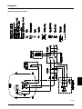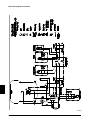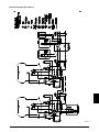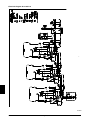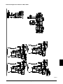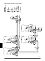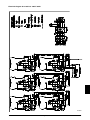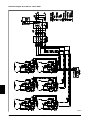
1
Compressor Model 3 motor / 3-4 / 6 motor / 6-4 / 6-15 / 6-25 12-25 / 12-40 / 18-40 / 24-40 / 36-150 Operating manual Betriebsanweisung Mode d’emploi Modo de empleo Gebruiksaanwijzing Betjeningsforskrift GB Operating manual.................................................................................................................................... 5 DE Betriebsanweisung................................................................................................................................... 8 FR Mode d’emploi........................................................................................................................................ 11 ES Modo de empleo.................................................................................................................................... 14 NL Gebruiksaanwijzing................................................................................................................................ 17 DK Betjeningsforskrift..................................................................................................................................20 Technical specifications.........................................................................................................................23 Technische Daten Caracteristiques techniques Detalles téchnicos Technische gegevens Tekniske specifikationer Diagrams................................................................................................................................................29 Zeichnungen Dessins Diagramas Tekeningen Diagrammer Spare parts............................................................................................................................................ 37 Ersatzteile Pieces detachées Piezas de recambio Onderdelenlijst Reservedele Figures................................................................................................................................................... 51 Abbildungen/Illustrationen Photos/illustrations Fotos/illustraciones Afbeeldingen/illustratien Figures Operating manual 4. Replace the cap on the air intake tube with the intake filter (fig. 2). 5. Connect pneumatic equipment. Information Please note that you can find the pictures and illustrations we are referring to on page 51. Important! The compressor oil may be aggressive towards certain gasket materials used in pneumatic equipment. We recommend Teflon, Viton, etc.. Do not use polycarbonate filter bowls. Contact your local JUN-AIR distributor if you need further information. GB Warning 6. Plug the compressor into an outlet switch of nominal voltage and ensure that fusing is adequate (see Technical Details). · Unless directions are followed and original spare parts used, physical injury or property damage may result. · Protect compressor against rain, moisture, frost, and dust. · Compressor is only suitable for installations with the nomi nal voltage stated on the motor plate. · Do not in any way block or prevent the normal functioning of the safety valve on the receiver. · Only connect pneumatic equipment suitable for the max. pressure indicated. · Do not operate compressor at ambient temperatures exceeding 35°C/95°F or falling below 0°C/32°F. · Do not touch compressor motor during operation as there is a risk of burn due to high temperatures. · Do not direct air flow at head or body. · When a flammable liquid is sprayed, there may be danger of fire or explosion, especially in closed rooms. · Always keep the compressor out of reach of children. 7. Start the compressor using the 0/1 switch on the pressure switch (fig. 3). The compressor will automatically switch off at the preset pressure. If the motor does not start it may be due to pressure in the receiver, and the motor will then start automatically when the pressure reduces to approx. 6 bar/87 psi. 8. Always keep the compressor in a vertical position as oil may run out of the intake filter. During transportation, mount the cap on the inlet. Mechanical noise from the compressor in connection with handling does not have any functional importance. Warning! Never mount the transportation cap on oil-lubricated compressors while there is still pressure in the compressor & pressure vessel, as this may cause a pressure build up in the motor housing. 9. Adjustment of pressure (fig. 4): Guarantee Provided that the operational instructions have been carried out, your JUN-AIR compressor is guaranteed against faulty material or workmanship for 2 years. The air receiver is guaranteed for 5 years. The guarantee does not cover damage caused by violence, misuse, incorrect repairs or use of wrong oil and unoriginal spare parts. Costs of transportation of parts/equipment are not covered by the guarantee. JUN-AIR’s Conditions for Sale and Delivery will generally apply. JUN-AIR International A/S reserves the right to change technical specifications/ constructions. How to operate the JUN-AIR compressor Your JUN-AIR compressor is very easy to operate. Observe the following simple instructions and you will get many years’ service from your compressor. 1. Visually inspect unit for shipping damage, contact your supplier immediately if you think the unit may have been damaged. 2. Always keep the compressor in a vertical position during use and transportation. 3. Place the compressor in a dustfree, dry and cool, yet frostfree, room. Do not install in a closed cupboard, unless adequate openings for ventilation are available (fig. 1). Ensure that the compressor stands firmly on the floor. A: Max. pressure adjustment (cut-out) B: Differential adjustment (cut-in) The cut-in pressure (normally 6 bar) is set by adjustment of differential screw B. Turn clockwise to reduce cut-in pressure. The cut-out pressure is set by even adjustment of the two screws A. (Cut-in pressure + differential = cut-out pressure). Turn clockwise to increase cut-out pressure. The switch is normally factory set for operation at 6-8 bar (approx. 90-120 psi). 10. Adjustment of CONDOR 4-16 press-switch (fig. 4a) The cut-out pressure (normally 16 bar) is set by adjustment of maximum pressure screw. (Cut-in pressure + different pressure = cut-out pressure). Turn clockwise to increase cut-out pressure. The cut-in pressure (normally 14 bar) is set by adjustment of differential screw. Turn clockwise to reduce cut-in pressure. The switch is normally from the factory set for operation at 14-16 bar. Technical details The max. operation of the compressor is 50% of the operation time, and the max. operation time is 15 min. at 8 bar/120 psi in each cycle. Consequently, 15 min. standstill is required before the next start. For tables with technical data and performance curves, see page 23. Operating manual Preventive compressor maintenance Weekly Monthly Annually Check oil level. During standstill the correct level is between the maximum and the minimum indications. Use only genuine SJ-27 synthetic oil. Do not overfill (fig. 5). Check the pumping time Drain condensate from air receiver (at a pressure of max. 2 bar/30 psi) (fig. 6). If fitted with auto drain, this will take place automatically, however, drain bottle has to be emptied. GB Important! Always use SJ-27 oil as other types of oil may cause serious mechanical damage to the compressor. Consequently, the warranty only applies if SJ-27 oil is used. The pumping time indicates the condition of the compressor provided that there are no leaks in the system where the compressed air may leak. Test the compressor as follows: 1. Empty the air receiver of compressed air (the pressure gauge shows 0 bar). If compressor is fitted with outlet filter, check and empty for water by pressing the black button. If fitted with auto drain, this will take place automatically. 2. Close the outlet on the air receiver and check that the drain cock is closed. 3. Start the compressor and note how long it takes until it switches off. Make sure that the pressure in the air receiver is 8 bar/120 psi as deviations may indicate the wrong results (see technical details). Check compressor, air tubes and equipment for leaks, and check the pumping time. Inspect and replace intake filter, if necessary. Important! Always test the compressor when cold as the time indicated refers to the pumping time of a cold compressor. The pumping time of a warm compressor is much longer and consequently, the result would be misleading. Clean the compressor with a soft, damp cloth. Dust and dirt prevent cooling. Check the O-ring in the non-return valve and replace if necessary (fig. 10) Note! Empty receiver of air before dismounting. Fault finding and repair Check filter and filter elements for optimum efficiency. Important! Switch off and isolate from electrical supply before removing any parts from the compressor. Empty air receiver of air before dismantling any parts of compressor unit’s pressure system. Test the safety valve by gently pulling the ring with pressure in the receiver (fig. 7). 1. Compressor does not start: Oil change In connection with repair of model 6 motors, e.g. change of valve plate or other internal motor parts or in case the compressor is installed in a very dusty environment, oil change may be necessary. Proceed as follows: a) No power from mains. Check fuses and plug. b) Breakage or loose joints in electrical connections. c) The starting relay is defective. Contact your JUN-AIR distributor. d) The pressure switch is defective and does not switch on the compressor. e) The thermal protection has switched off the compressor due to overheating. When cooled the compressor will automatically turn on at a suitable operation tempera- ture. Go through the points in section 4. f) Pressure in the air receiver is too high for activation of the pressure switch. The pressure switch makes circuit only when pressure has dropped to preset start pressure. Empty the receiver. g) The compressor has not been unloaded and there is back pressure on the piston. Dismount and check unloader valve (fig. 9). The back pressure may be due to a leaking non-return valve causing the compressed air in the receiver to leak back into the compressor motor. Dismount the non-return valve and clean or change O-ring (fig. 10). h) Capacitor defective. 1. Remove the ribbed cover by loosening the 4 screws (fig. 8). 2. Tilt the motor towards side with outlet and at the same time hold the internal motor parts in place with hand. Pour all oil out of housing (fig. 8). In case of dirt particles at the bottom of the motor housing, clean with a rag. Note! Waste oil is to be handled according to the environmental rules in force in the country. 3. Tilt the motor back and fill with SJ-27 oil (approx. 0.75l) (fig. 8). 4. Clean the edge of casing and cover. Check the O-ring of the ribbed cover. 5. Replace the ribbed cover and check during operation that the O-ring is placed correctly to ensure a 100% tight closing between housing and cover. Operating manual 2. Compressor operates, but pressure does not increase in tank (or increases too slowly): a) The cap on the intake tube has not been removed and replaced by the intake filter (fig. 2). b) Intake filter is clogged. Replace. c) Leaks in fittings, tubes or pneumatic equipment. Check with soapy water. Pressure drop is not to exceed 1 bar per hour. Drain moisture at least once a week. Alternation/repair No welding must be made on pressurized parts. Safety valve Ensures that PS will not be exceeded. Never adjust to a higher pressure than PS. The capacity of the valve must be calculated in accordance with the volume of air supplied by the compressor. (PS = Maximum working pressure of the receiver) d) Clogged non-return valve or pressure pipe. Clean or replace the parts (fig. 10). e) Air leaks from the unloader valve when the compressor is operating. Check or replace the unloader valve (fig. 9). f) Defective valve plate. Contact your JUN-AIR distributor. GB 3. Loud noise from compressor: a) Most likely broken suspension spring(s). Replace the spring and ensure that motor position is horizontal. Declaration of Conformity b) The internal pressure pipe touches the rib cover or the cylinder block. Dismount the rib cover and bend the pressure pipe away. NOTE: The declaration of conformity is only valid for units operating at 230 V/50 Hz, 3x400 V/50 Hz, 12 V DC or 4. Compressor gets very hot and/or uses a lot of oil: a) Incorrect oil level. The level must appear in the oil level glass (fig. 5). b) Wrong oil has been filled in the compressor. Use only SJ-27 synthetic lubricant which has the correct viscosity. c) Leaks. See point 2c. 24 V DC. The manufacturer, JUN-AIR International A/S, declares that the products mentioned in this manual are in conformity with: • 87/404/EEC - 90/488/EEC - 93/68/EEC Council Directive relating to Simple Pressure Vessels d) Clogged intake filter. See point 2b. • 89/392/EEC - 91/368/EEC - 93/44/EEC - 93/68/EEC Council Directive of Safety of Machinery e) Too high ambient temperature. Do not install the compressor in a cabinet unless adequately ventilated (fig. 1). • 89/336/EEC Council Directive of Electric Magnetic Compatibility f) The compressor is overloaded (i.e. it is operating more than 50% of the operation time). Contact your JUN-AIR distributor. • 73/23/EEC Low-voltage Directive 5. Compressor starts when no air is being used: a) Leaks. See point 2c. 6. Compressor starts and stops more frequently than usual: Flemming Frisch Andersen a) Condensate in the air receiver. Empty the receiver by means of the drain cock (fig. 6). Test and Certification Administrator b) Leaks. See point 2c. Pressure vessel Pressure tested at: 4-25 liter: 40-50 liter: 24 bar 18.3 bar Directions for use Application Receiver for compressed air. Receiver specifications See name plate. Installation Tubes, etc. must be made of suitable materials. Placement Observe the working temperature of the receiver. Ensure that sufficient room for inspection/maintenance is available in a horizontal position. The receiver must be kept in a horizontal position. Corrosion protection The surface treatment must be maintained as required. Internal inspection at least every 5 years. Operating manual Modo de empleo afirmado sobre el suelo. 4. Reemplaze la tapa de circulación con el filtro de ingreso (fig. 2). 5. Conecte el compresor al equipo neumático. Información Puede encontrar las fotos y figuras a los cuales nos referimos a la página 51. Importante! Algunos materiales son incompatibles con el aceite JUN-AIR. Consecuentemente se recomendan juntas de Teflon/Viton en los equipos neumáticos. Filtros con vidrio de policarbono no deben utilizarse. En caso de dudas, contacte a su distribuidor JUN-AIR. Advertencias preliminares · · · · · · · ES · · · La inobservancia de las instrucciones, la utilización de piezas de recambio no originales, pueden ocasionar daños fisicos o materiales. Proteja el compresor de la lluvia, de la humedad, de la helada y de polvo. Conectar el compresor unicamente a instalaciones con el voltaje nominal indicado en la placa del motor. Asegure que nunca se bloquea la válvula de seguridad, y no impida su funcionamiento normal. Utilice exclusivamente los equipos neumáticos apropriados para la presión máxima indicada. No utilice el compresor a temperatura ambiente superior a 35°C/95°F, o inferior a 0°C/32°F. No toque el motor, cuando el compresor está funcionando. La alta temperatura puede ocasionar quemaduras. No dirija el chorro de aire al cuerpo. Al pulverizar un liquido inflamable puede haber peligro de incendia o explosión, especialmente en lugares cerrados. Cuando utilice el compresor mantengalo fuera del alcance de los niños y nunca lo deje sin vigilancia. 6. Conectar el compresor a una toma eléctrica del voltaje adecuado, comprobando que los fusibles son adecuados. Referirse a los datos téchnicos en cuanto el consume de Amperos. 7. Ponga en marcha el compresor por medio del botón (0/1) del presostato (fig. 3). La presión subirá en el manómetro del calderín, y el motor se parará automáticamente, a la presión ajustada en el presostato. Si el motor no se pone en marcha, se debe posiblemente eso al hecho que el tanque de aire está con presión. El motor se pone automáticamente en marcha cuando la presión ha bajado a una presión aproximada de 6 bar. 8. Si se muda el compresor de sitio, asegure que siempre está en posición vertical, para evitar fugas de aceite por el filtro de ingreso. Durante el transporte, monte la tapa por el tubo de ingreso de aire. Ruidos metálicos eventuales durante el transporte, o el cambio de lugar, no tienen ninguna importancia funcional. Atención! Nunca montar la tapa de transporte mientras el tanque de aire esté con presión. Puede haber peligro de presión en el carter. 9. Ajuste de la presión de régimen (fig. 4): Garantía Su compresor JUN-AIR está garantizado durante 2 años contra fallos de materiales o de construcción, siempre que se cumplan las instrucciones de uso. El tanque está garantizado durante 5 años. La garantía no cubre los daños causados por violencia, mala utilización, reparaciones incorrectas o uso de recambios y aceite no originales. El coste de transporte de recambios o equipos no está cubierto por la garantía. Las Condiciones Generales de Venta y Entrega de JUN-AIR International A/S serán aplicables. JUN-AIR International A/S se reserva el derecho a cambiar las especificaciones técnicas o de construcción sin aviso. A: Regulación de la presión de interrupción. B: Regulación de la presión diferencial (arranque). La presión de arranque del compresor (normalmente 6 bar) se regula por medio del tornillo B de diferencial. Girarlo en el sentido de las agujas del reloj para reducir la presión de arranque. La presión de interrupción del compresor se regula por medio de los tornillos A - justándoles igualmente. (Presión de arranque + diferencial = presión de interrupción). Girar en el sentido de las agujas del reloj para incrementar la presión de interrupción. El compresor es regulado en fábrica para funcionamiento entre 6 y 8 bar. 10. Instructiones para ajustar el presostato Condor 4/16 (fig. 4a) Su compresor JUN-AIR es muy fácil de manejar. Siga las sencillas instrucciones que damos a continuación, y conseguirá un servicio sin problemas durante años. La presión de interrupción (normalmente 16 bar) se regula por medio del tornillo de presión maximal. (Presión de arranque + diferential = presión de interrupción). Girar en el sentido de la agujas del reloj par incrementar la presión de interrupción. 1. Haga una inspección visual. Si observa desperfectos ocasionados durante el transporte, póngase inmediatamente en contacto con nosotros. La presión de arranque (normalmente 14 bar) se regula por medio del tornillo differential. Girar en el sentido de la agujas del reloj par reducir la presión de arranque. Normalmente, el presostato es regulado en fábrica para funcionamiento entre 14 y 16 bar. Modo de empleo y mantenimiento del JUN-AIR 2. Coloque siempre el compresor verticalmente durante el transporte y el uso. 3. Coloque el compresor en un emplazamiento libre de polvo, fresco, seco y donde no sufra la acción del hielo. Si va a colocarlo en el interior de un armario ponga aberturas para ventilación (fig. 1). Asegúrese de que el compresor queda 14 Modo de empleo Detalles técnicos En operación continua, el compresor no debe funcionar más que el 50% del tiempo. A 8 bar, el compresor no debe funcionar más que 15 minutos en continuo, y tendrá que respectar una parada de 15 minutos, antes del ciclo siguiente. Mira la página 23 para encontrar los datos técnicos y las curvas de rendimiento. 3. Levante el motor a la posición vertical, y efectúe el relleno de aceite. Aprox. 0,75 ltr. de aceite SJ-27. (fig. 8). 4. Limpie cuidadosamente el borde de la tapa y del carter, verificando el estado de la junta. 5. Coloque la tapa, verificando que la junta esté colocada correctamente, y fijando los tornillos. Comprobe la estanqueidad de la tapa poniendo el compresor en marcha. Mantenimiento preventivo del compresor Semanal Mensual N.B. Respecte el reglamento ambiental para la manipulación, y la destrucción del aceite usado. Anual Controlar el nivel de aceite. El nivel correcto será entre las lineas marcadas para minímo y máximo. Utilizar unicamente aceite original de calidad SJ-27 (fig. 5). Vaciado de agua condensada en el tanque (fig. 6) (Presión máxima 2 bar). Si el compresor lleva un sistema de drenaje automático, la purga se efectua automaticamente. Sin embargo, no omitir de vaciar la botella de agua condensada. Importante! La utilización de aceite de otra calidad que la del aceite original SJ-27 resulta en graves daños mécanicos del motor, después de poco tiempo. En este caso se anula la garantía. Verificación del tiempo de bombeo El tiempo de bombeo de 0 a 8 bar puede dar una indicación del estado del compresor, siempre que no haya fugas de aire en el sistema. Procede como sigue: 1. Vacie completamente el tanque de aire (el manómetro indica 0 bar). Si el compresor lleva un filtro a la salida de aire, verificar este filtro y purgar activando el bontón negro inferiór. Si el filtro lleva drenaje automático, la purga se efectua automaticamente. 2. Cierra la salidad de aire por el tanque, y comprobe que la llave de drenaje está cerrada. 3. Ponga en marcha el compresor, y note el tiempo utilizado, hasta que el presostato haya desconectado el motor. Comprobe la presión en el manómetro, que debe indicar 8 bar, para evitar errores de medida (ve detalles técnicos). Comprobar el funcionamiento mecánico del motor, de la tubería, y de la instalación de aire. Comprobar el tiempo de bombeo de 0 a 8 bar. Importante! El resulto depende de la temperatura del motor. Si el motor es caliente, el tiempo de operación será más largo. Como los valores indicados son obtenidos con un motor frío, efectue la operación con motor frío, para obtener una base comparable. Comprobar el filtro de ingreso. Reemplazar eventualmente. Limpiar el motor con aire comprimido, para quitar polvo. Polvo y suciedad impiden refrigeración del motor. Diagnóstico de fallas y reparaciones Verificar la junta »o« de la válvula de retención. Reemplazar eventualmente (fig. 10). Asegurarse que el tanque de aire se encuentra vacío antes de desmontar la válvula. Importante! Desconectar la coriente antes de desmontar cualquier parte del compresor. Asegurarse que el tanque de aire se encuentra vacío, antes de desarmar cualquier parte del sistema de presión del compresor. Comprobar el filtro y los elementos de filtro. Comprobar la válvula de seguridad, tirando del anillo mientras el tanque esté con presión (fig. 7). 1. El compresor no funciona: Cambio de aceite Con ocasión de reparaciones del motor modelo 6 – por ejemplo si se cambian la válvula de laminas o las piezas internas del motor - o si el compresor está instalado en lugar polvoriento, el cambio del aceite del motor puede ser necesario. En este caso procede como sigue: 1. Desmonte la tapa, aflojando los cuatro tornillos (fig. 8). 2. Bascule el motor por el lado de la descarga, sujetando las piezas internas del motor con la mano. Vacie el aceite completamente (fig. 8). Utilice una pistola sopladora para eliminar los resuidos eventuales del fondo del carter. a) No hay corriente en la línea principal. Compruebe los fusibles y tomacorrientes. b) Rotura o uniones sueltas en las conexiones eléctricas. c) Relé de arranque defectuoso. Pongase en contacto con su distribuidor. d) Presostato defectuoso, que no arranca el motor. e) Modo de empleo El protector del motor ha cortado el motor, debido recalentamiento. El compresor se pone automáticamente en marcha al alcanzar la temperatura adecuada y normal para el funcionamiento. Refierese tambíen al paragrafo 4. 15 ES f) g) La presión en el tanque es demasiado alta para activar el presostato. Vacie el tanque. El presostato se activa solamente si la presión está inferiór a la presión de arranque. Tanque de presión El compresor no está descargado. El pistón está con contrapresión. Desmonte y comprobe la válvula de descarga (fig. 9). Una fuga en la válvula de descarga, por ejemplo, resulta en contrapresión. En este caso, el aire comprimido del tanque vuelve al motor del compresor. Desmonte la válvula de descarga, y límpiala. Reemplaze eventualmente la junta „O“ (fig. 10). h) Condensador defectuoso. 2. El compresor funciona, pero la presión no aumenta (el tiempo de bombeo de 0 a 8 bar es incorrecto): a) La tapa de circulación no está removida, y reemplazada con el filtro de ingreso (fig. 2). b) El filtro de aspiración está cegado. Substituyalo. c) Fugas en las conexiones, mangueras o equipo neumático. Compruebe por medio de agua jabonosa. La perdida de presión no debe exceder 1 bar cada hora. d) Válvula de retención, o tubería de presión, obstruidos. Limpie o reemplaze esas piezas (fig. 10). e) Fugas en la válvula de descarga, mientras el compresor está funcionando. Limpie o reemplaze la válvula (fig. 9). f) Válvula de laminas defectuosa. Póngase en contacto con su distribuidor. 3. Fuerte ruido del compresor: ES a) Resorte de suspensión del motor roto. Reemplaze el resorte, y comprobe visualmente que el motor quede horizontal, después de esta reparación. b) La tubería de presión interna toca la tapa, o el cilindro. Desmonte la tapa, y ajuste la posición de la tubería de presión. 4. El compresor calienta mucho, y usa mucho aceite: a) Nivel de aceite demasiado alto. El nivel debe aparecer en el visor de vidrio, entre las líneas marcadas (fig. 5). b) Se está usando aceite lubricante inadecuado. Utilize únicamente el de calidad SJ-27, con la viscosidad adecuada. c) Fugas de aire en uniones y cables. Ve punto 2c. d) Filtro de ingreso obstruido. Ve punto 2b. e) Temperatura ambiente muy alta. Nunca poner el compresor en un armario, o caja, a menos que cuente con una adecuada ventilación (fig. 1). f) Compresor sobrecargado (es decir, más de los 50%). Póngase en contacto con su distribuidor. 5. El compresor funciona, aún cuando no haya habido consumo de aire: a) Fugas. Ve punto 2c. 6. El compresor arranca, y para, con más frecuencia que lo usual: a) Mucho contenido de condensado en el tanque. Vacie el tanque por medio de la llave de purga. (fig. 6). b) Fugas. Ve punto 2c. 4-25 litros: 24 bar 40-50 litros: 18.3 bar Tanque para aire comprimido. Presión probada a: Modo de empleo Aplicación Especificaciones del tanque Mira la chapa. Instalación Las tuberias se deben efectuar de materiales convenientes. Colocación Observa la temperatura de funcionamiento. Mantiene demasiado espacio por inspección/mantenimiento. El tanque se debe poner en un lugar horizontal. Tratamiento anticorrosivo El tratamiento superficial se debe mantener según sea preciso. Un examen visual se debe efectuar cada 5 años como mínimo. Vacíe el agua condensada una vez por semana como mínimo. Construcción y reparación No solde en las partes presurizadas. Válvula de seguridad Esa asegura que la PS no está excedida. La válvula no se debe nunca ajustar a una presión más alta que la PS. La capacidad de la válvula se debe calcular según la cantidad de aire que suministra el compresor. (PS = la presión máxima del tanque) Declaración de Conformidad IMPORTANTE: La declaración de conformidad se refiere solamente a unidades que marchan a 230 V/50 Hz, 3x400 V/50 Hz, 12 V DC o 24 V DC. El fabricante, JUN-AIR International A/S, declara que los productos mencionados en este modo de empleo están conformes con: • 87/404/CEE - 90/488/CEE - 93/68/CEE Directriz en relación a recipientes a presión simple. Mira al verso. • 89/392/CEE - 91/368/CEE - 93/44/CEE - 93/68/CEE Directriz de Seguridad de maquinaria • 89/336/CEE Directriz de Compatibilidad eléctrica magnética • 73/23/CEE Directriz de baja tensión Flemming Frisch Andersen Test and Certification Administrator 16 Modo de empleo Technical specifications Motor size 3 Voltage Volt 100 100 120 200 200 230 230 Frequency Hz 50 60 60 50 60 50 60 Power HP 0,20 0,20 0,20 0,18 0,18 0,18 0,18 kW 0,15 0,15 0,15 0,13 0,13 0,13 0,13 Displacement FAD @ 8 Bar *** Max. pressure** l/min 17 20 20 17 20 17 20 CFM 0,60 0,71 0,71 0,60 0,71 0,60 0,71 l/min 11 13 13 11 13 11 13 CFM 0,46 0,39 0,46 0,46 0,39 0,46 0,39 Bar 8 8 8 8 8 8 8 PSI 120 120 120 120 120 120 120 Max. current Amps 2,8 2,7 2,4 0,9 0,9 0,9 0,9 Noise level @ 1 m dB(a) 35 35 35 35 35 35 35 Weight Kg Dimensions (l x w x h) 9 Lbs 20 mm 290 x 190 x 210 Inch 11.4 x 7.5 x 8.3 Motor size 6 Voltage Volt 100 100 120 200 200 230 Frequency Hz 50 60 60 50 60 50 60 Power HP 0,54 0,54 0,54 0,46 0,46 0,46 0,46 kW 0,34 Displacement FAD @ 8 Bar *** Max. pressure** 230 0,40 0,40 0,40 0,34 0,34 0,34 l/min 50 60 60 50 60 50 60 CFM 1,77 2,12 2,12 1,77 2,12 1,77 2,12 l/min 32 37 37 32 37 32 37 CFM 1,13 1,31 1,31 1,13 1,31 1,13 1,31 Bar 8 8 8 8 8 8 8 PSI 120 120 120 120 120 120 120 Max. current Amps 5,7 5,2 6,2 2,9 2,9 2,9 2,9 Noise level @ 1 m dB(a) 45 45 45 45 45 45 45 Weight Kg Dimensions (l x w x h) 14 Lbs 31 mm 280 x 190 x 240 Inch 11.0 x 7.5 x 9.4 Motor size Voltage Volt 100 100 120 200 200 230 230 Frequency Hz 50 60 60 50 60 50 60 Power Displacement FAD @ 8 Bar *** HP 1,08 1,08 1,08 0,92 0,92 0,92 0,92 kW 0,79 0,79 0,79 0,68 0,68 0,68 0,68 l/min 100 120 120 100 120 100 120 CFM 3,53 4,24 4,24 3,53 4,24 3,53 4,24 l/min 64 74 74 64 74 64 74 CFM 2,26 2,61 2,61 2,26 2,61 2,26 2,61 Bar 8 8 8 8 8 8 8 PSI 120 120 120 120 120 120 120 Max. current Amps 11,4 10,4 12,4 5,8 5,8 5,8 5,8 Noise level @ 1 m dB(a) 48 48 48 48 48 48 48 Max. pressure** * 12 Neutral is required ** Higher pressure available upon request Technical modifications reserved Technical specifications 23 Motor size 18 Voltage Volt 100 200 200 230 Frequency Hz 50 50 60 50 60 Power HP 1,62 1,38 1,38 1,38 1,38 kW 1,19 1,01 1,01 1,01 1,01 l/min 180 150 180 150 180 CFM 6,36 5,30 6,36 5,30 6,36 Displacement FAD @ 8 Bar *** Max. pressure** 230 l/min 111 96 111 96 111 CFM 3,92 3,39 3,92 3,39 3,92 8 8 8 8 8 Bar PSI 120 120 120 120 120 Max. current Amps 18,6 8,7 8,7 8,7 8,7 Noise level @ 1 m dB(a) 50 50 50 50 50 Motor size 24 Voltage Volt Frequency Hz 50 60 50 60 50 60 60 50 60 Power HP 1,84 1,84 1,84 1,84 1,84 1,84 1,84 1,84 1,84 kW 1,35 1,35 1,35 1,35 1,35 1,35 1,35 1,35 1,35 Displacement FAD @ 8 Bar *** Max. pressure** 200 200 230 230 3x200 3x200 3x208 3x400* 3x400* l/min 200 240 200 240 200 240 240 200 240 CFM 7,06 8,48 7,06 8,48 7,06 8,48 8,48 7,06 8,48 l/min 128 148 128 148 128 148 148 128 148 CFM 4,52 5,23 4,52 5,23 4,52 5,23 5,23 4,52 5,23 8 8 8 8 8 8 8 8 8 Bar PSI 120 120 120 120 120 120 120 120 120 Max. current Amps 11,6 11,6 11,6 11,6 8,7 8,7 8,7 5,8 5,8 Noise level @ 1 m dB(a) 56 56 56 56 56 56 56 56 56 Motor size 36 Voltage Volt Frequency Hz 50 60 60 50 60 Power HP 2,76 2,76 2,76 2,76 2,76 kW 2,03 2,03 2,03 2,03 2,03 Displacement FAD @ 8 Bar *** Max. pressure** 3x200 3x200 3x208 3x400* 3x400* l/min 300 360 360 300 360 CFM 10,59 12,71 12,71 10,59 12,71 l/min 192 222 222 192 222 CFM 6,78 7,84 7,84 6,78 7,84 8 8 8 8 8 Bar PSI 120 120 120 120 120 Max. current Amps 11,6 11,6 11,6 8,7 8,7 Noise level @ 1 m dB(a) 58 58 58 58 58 * Neutral is required ** Higher pressure available upon request Technical modifications reserved 24 Technical specifications Compressor unit Model 3-4 Tank size liter Weight Dimensions (l x w x h) 6-4 6-15 6-25 4 4 15 25 US gallon 1,1 1,1 4,0 6,6 kg 18 23 26 29 lbs 40 51 57 64 mm 384 x 333 x 342 384 x 333 x 342 378 x 378 x 485 378 x 378 x 555 Inch 15.1 x 13.1 x 13.5 15.1 x 13.1 x 13.5 14.9 x 14.9 x 19.1 14.9 x 14.9 x 21.9 Pumping time (0-8 bar/0-120 psi) @ 50 Hz sec. 160 60 220 365 @ 60 Hz sec. 135 50 185 305 Noise level @ 1 m @ 50 Hz dB(a) 35 45 45 45 @ 60 Hz dB(a) 35 45 45 45 24-40 Model Tank size Weight Dimensions (l x w x h) 12-25 12-40 18-40 liter 25 40 40 40 US gallon 6,6 10,6 10,6 10,6 kg 45 48 62 84 lbs 99 106 137 185 mm 425 x 400 x 595 556 x 446 x 581 556 x 446 x 557 556 x 446 x 623 21.9 x 17.6 x 24.5 Inch 16.7 x 15.7 x 23.4 21.9 x 17.6 x 22.9 21.9 x 17.6 x 21.9 Pumping time (0-8 bar/0-120 psi) @ 50 Hz sec. 185 275 185 140 @ 60 Hz sec. 155 225 150 115 Noise level @ 1 m @ 50 Hz dB(a) 48 48 50 56 @ 60 Hz dB(a) 48 48 50 56 Model 36-150 Tank size Weight Dimensions (l x w x h) Pumping time (0-8 bar/0-120 psi) Noise level @ 1 m liter 150 US gallon 39,6 kg 164 lbs 362 mm 1287 x 454 x 775 Inch 50.7 x 17.9 x 30.5 @ 50 Hz sec. 345 @ 60 Hz sec. 285 @ 50 Hz dB(a) 58 @ 60 Hz dB(a) 58 * Neutral is required ** Higher pressure available upon request Technical modifications reserved Technical specifications 25 Translations English German French Spanish Dutch Danish Voltage Spannung Voltage Voltaje Voltage Spænding Frequency Frequenz Fréquence Frequencia Frequentie Frekvens Motor HP Motor HP Moteur CV Motor CV Motor HP Motor HK Displacement Ansaugleistung Débit Aire aspirado Capaciteit Ydelse Max. pressure Max. Druck Pression de service max. Presión de régimen máx. Max. druk Max. arbejdstryk Max. current Stromverbrauch Consommation Corriente máxima Max. stroom Strømforbrug Tank size Behältervolumen Volume réservoir Volumen de tanque Tankvolume Beholderstørrelse Weight Gewicht Poids Peso Gewicht Vægt Dimensions (l x w x h) Abemessungen (l x b x h) Dimensions (l x p x h) Dimensiones (l x a x h) Afmetingen (l x w x h) Dimensioner (l x b x h) Noise level Schallemissionen Niveau sonore Nivel de ruido Geluidsniveau Lydniveau Pumping time Pumpzeit Temps de refoulement Tiempo de bombeo Pomptijd Oppumpningstid Higher pressure available upon request Höhere Druck lieferbar Pression supérieure sur demande Presión mayour sobre demanda Hogere druk op aanvraag Højere tryk kan leveres Neutral is required Null-leiter ist erforderlich Neutre nécessaire Neutro necesairo Neutraal noodzakelijk N-leder kræves Technical modifications reserved Technische Änderungen vorbehalten Droits réservés pour modifications techniques Reservamos el derecho a cambiar estas especificaciones técnicas sin previo aviso Technische wijzigingen voorbehouden Ret til ændringer forbeholdes 26 Technical specifications Performance Model 3 cu.ft/min. Ltr./min. 0,7 20 Model 6 cu.ft/min. Ltr./min. 60 2,0 50 0,6 1,5 40 15 60 Hz 0,5 60 Hz 30 1,0 0,4 50 Hz 20 10 0 1 0 2 20 3 40 4 6 5 60 7 100 80 8 bar 0 120 psi 0 Model 12 cu.ft/min. Ltr./min. 120 4,0 1 2 20 3 40 4 6 5 60 7 100 80 8 barg 120 psig Model 18 cu.ft/min. Ltr./min. 180 6,0 160 100 3,0 50 Hz 5,0 140 80 60 Hz 120 60 Hz 4,0 2,0 60 50 Hz 100 50 Hz 3,0 40 0 1 0 2 20 40 7,0 4 6 5 60 7 100 80 8 bar 0 120 psi 0 Model 24 cu.ft/min. Ltr./min. 240 8,0 3 80 1 2 20 40 12,0 200 10,0 180 4 6 5 60 7 100 80 8 bar 120 psi Model 36 cu.ft/min. Ltr./min. 360 220 3 320 280 240 60 Hz 9,0 6,0 160 200 60 Hz 5,0 140 8,0 50 Hz 160 50 Hz 0 0 1 2 20 3 40 4 60 6 5 80 7 100 8 bar 0 120 psi 0 Technical specifications 1 2 20 3 40 4 60 6 5 80 7 100 8 bar 120 psi 27 Diagrams Electrical diagram for model 3 6070010 Diagrams 29 Electrical diagram for model 6 6070160 30 Diagrams Electrical diagram for model 12 6070210 Diagrams 31 Electrical diagram for model 18 6070260 32 Diagrams Electrical diagram for model 24 - 400V / 50Hz 6070310 Diagrams 33 Electrical diagram for model 24 - 230V / 50-60Hz 6070311 34 Diagrams Electrical diagram for model 36 - 400V / 50Hz 6070360 Diagrams 35 Electrical diagram for model 36 - 230V / 50Hz 6070361 36 Diagrams Spare parts 3010099 Receiver 4l without inspection plug CE, silver 4560100 Casing bottom f/3 motor 230V silver (new) 3050099 Receiver 4l with inspection plug CE, silver, internally coated 4561000 Casing bottom f/6 motor silver 4571000 Rib cover f/6 motor, silver 3210095 Receiver 15l with inspection plug ASME, silver 4574300 Rib cover f/3 and 4 motors silver 3210099 Receiver 15l with inspection plug, CE, silver, fluid in nozzle 4610201 Cylinder head f/3 motor (new) 4610501 Spring w/bushing f/3 motor (new) 4610601 Top bearing f/3 motor (new) 4611301 Cover f/terminal board f/3 motor (new) 4611350 Bracket f/terminal board f/3 motor (new) 4611360 Bracket f/klixon f/3 motor (new) 4646000 Gasket f/cover (= 4548000) 4649500 Bolt f/safety valve f/3 motor 4656000 Bolt f/cylinder head f/3 motor 4750000 Control lamp 230V 4750200 Control lamp 120V 5030000 Pressure switch MDR 2/11 compl. 5033000 Pressure switch MDR 21/11 w/unloader 5035000 Pressure switch MDR 2/11 w/unloader 5075010 Pressure switch MDR 21/11 UL compl. 5075100 Pressure switch MDR21/11 UL complete w/unloader 5085000 Pressure switch MDR 4S/11 compl. 5130000 Gauge リ40 0-16 bar 1/8” down 5210000 Capacitor start 70uF 5230000 Capacitor start 160uF UL 5320226 Handle, multi complete 5340001 Handle f/6-15/6-25 complete 5410000 Oil level glass compl. 5410000 Oil level glass compl. 5412000 Intake filter f/6 motors, complete 5414000 Oil inlet screw w/gasket 5414500 Non return valve 5416000 Safety valve 10 bar / 145 psi 5416200 Safety valve 16 bar / 232 psi 5416200 Safety valve 16 bar / 232 psi 5418000 Drain cock 1/4” 4l 3410092 Receiver 25l with inspection plug, ASME, silver 3410099 Receiver 25l with inspection plug, CE, silver 3512097 Receiver 40l with inspection plug, CE/ASME, silver 3695298 Receiver 150l with inspection plug, CE, silver 4070500 Activated carbon filter DH AC-0003G 4071000 Filter 5um w/manual drain 4071020 Regulator R07-280-RNMG, 10 bar 4071030 Filter regulator 5um w/manual drain 4071055 Filter 0.01um w/manual drain 4071080 Lubricator L07-220-MPMG 4110000 Rapid coupler 1/4” external thread CEJN 4120000 Nipple 1/4” 4130000 Hose tail nipple 1/4” f/rapid coupler 4210000 Trolley f/6-10/15/25 4211000 Trolley f/6-4/3-1.5 4310000 Blow gun black 4311000 Blow gun black f/inflators 4380000 Ball inflator 4381000 Bicycle inflator 4382000 Car tyre inflator 4383000 Hose clamp 8-12 mm 4410000 PVC air hose 1/4” 4430000 Recoil air hose 1/4” 7.5m black 4520000 Overload protector f/6 motor 230V 4521000 Overload protector f/6 motor 120V 4522001 Overload protector f/3 motor 230V (new) 4522201 Overload protector f/3 motor 120V (new) 4522500 Overload spring f/6 motor 4523000 Starting relay 230V f/6 motor 4524000 Starting relay 120V f/6 motor 4526001 Starting relay f/3 motor 230V (new) 4526201 Starting relay f/3 motor 120V (new) 4526500 Terminal box compl. f/3 and 6 motors 4526600 Cover f/terminal box f/3 and 6 motors 4527000 Fastening spring f/3 and 6 motors 4528000 Bolt f/top bearing f/6 motor 4529000 Top bearing f/6 motor 4545000 Cover f/6 motor 4546000 Gasket f/cover f/6 motor 4547000 Pressure pipe f/6 motor (incl. gasket) 4548000 Gasket f/pressure pipe f/6 motor 4549000 Bolt f/pressure pipe f/6 motor 4550000 Copper washer f/6 motor 4551000 Suspension spring f/6 motor 4555000 Cylinder head f/6 motor 4556000 Bolt f/cylinder head f/6 motor 5419500 Drain cock 1/4” 15l 5420000 Drain cock 1/4” 25l 5421001 Drain cock 1/4” 40l (new) 5425000 Distributor f/non return valve compl. 5425000 Distributor f/non return valve compl. 5425500 Safety valve TÜV 10 bar 5426500 Safety valve TÜV 16 bar 5427000 Connecting piece 1/4” 5429000 Adaptor 5-way compl. 5429100 Adaptor 4-way compl. 5429500 Adaptor 2-way compl. 5451400 Fan compl. 120V 120x120mm 5451500 Fan compl. 230V 120x120mm 5453000 Fan guard 120x120 5470251 Spare parts kit f/replacement of valve plate f/3 motor (new) 5470300 Spare parts kit f/replacement of valve plate f/6 motor Spare parts 37 5512000 Label ”Min-Max” 7024000 Double nipple 1/4” L= 26 mm 5610000 Oil SJ-27 in 0.5l bottle 7070500 Connection piece f/non-return valve model 12 5612300 Drain bottle 1 l multi supplied separately incl. bracket for pipe mounting and magnet 7070600 Connection piece f/non-return valve model 12-25 7071000 T-piece 1/8” 5825000 Spring f/pressure control valve 7071400 T-piece Condor 5940000 Plastic insulation f/electric equipment 7071400 T-piece Condor 5950000 Plastic slide f/electric equipment 7080010 Distributor 6 way f/18-40 5960000 Cable relief 7084000 Adaptor f/36-90 6214000 Copper washer Ø10xØ6x1 mm 7110000 Screw f/pressure control valve 6221000 Gasket f/pressure control valve 7140000 Housing f/pressure control valve 6235000 Gasket f/oil filling 7156000 Extension piece f/cock short 6241800 O-ring f/1” plug - 32x5 mm 7156100 Extension piece f/cock long 6244000 O-ring f/rib cover 6 motor 7157001 Extension piece w/through 1/4” 6244200 O-ring f/rib cover 3/4 motor 7164200 Cross connector 6245800 O-ring Ø47x5 f/1 1/2” plug 7164900 Plug 1” f/inspection 6246000 O-ring f/2” plug 7166033 Plug 1 1/2” f/inspection ASME 6250000 Socket 25 mm black 7166800 Plug 2” galvanized 6252010 Socket f/handle 3-1.5/6-4 Ø22 7172800 Spacer f/600-40/50B 6253000 Rubber base f/handle Ø25x30 M8x8 7172820 Spacer f/2x600 6253200 Rubber base f/3-4000 models 7180000 Elbow 1/4” int./ext. KRG 6271000 Rubber grommet f/6 motor 7181002 Elbow 1/4” x 1/4” f/outlet 6272000 Rubber grommet f/3-4 motor 7190000 Elbow 1/8” 6290200 Plastic handle black Ø22 mm 7190000 Elbow 1/8” 6312000 Bolt M8x35 FZB 7525000 Hose tail f/coupling nut 1/4” 6313200 Bolt M6x30 FZB 7525000 Hose tail f/coupling nut 1/4” 6317000 Nut M12 DIN934-8 7525000 Hose tail f/coupling nut 1/4” 6320200 Counter nut M8 flat FZB 7525000 Hose tail f/coupling nut 1/4” 6330000 Screw CHJ M4x5 FZB 7562000 Nipple f/pressure control valve 6338000 Unbraco boltUNF 10-32 3/4” 7566000 Bushing 1/4” x 1/4” 6340500 Unbraco plug 1/8” 7566200 Bushing 1/4” x 1/4” L = 35 mm 6341900 Unbraco bolt M6x16 FZB 7567100 Bushing 1/2” x 1/4” 6341950 Unbraco bolt M6x25 FZB 7573000 Nut f/rib cover 6 motor 6350000 Washer ø23x11.5x1.5 FZB 7573500 Nut f/rib cover 3 motor 6351000 Clamp f/electrical equipment 7575000 Coupling nut 1/4” 6356600 Washer 3/16” x 30 mm 4 motor 7575000 Coupling nut 1/4” 6357800 Washer Ø28.5 x Ø13 x 1.5 FZB 8105001 6372700 Lock nut M8 FZB Bracket f/2xM3, 2xM4, 2xM6, 2xOF302, OF302, 1000, 2000 15-25l, painted 6413000 Flex hose 1/8” 13 (15) cm 8110601 Motor foundation f/36-150, painted 6417000 Flex hose 1/8” 17 (19) cm 8111501 Motor foundation f/12-40, painted 6420000 Flex hose 1/8” 20 (22) cm 8111611 6426000 Flex hose 1/8” 26 (28) cm Motor foundation f/3x6, 4x3, 4x4, 4xOF302, 4x6, 2x1000, 2x2000-40, painted 6433000 Flex hose 1/8” 33 (35) cm 8132000 Mounting bracket f/fan 6439000 Flex hose 1/8” 39 (41) cm 6450000 Flex hose 1/8” 50 (52) cm 6463000 Flex hose 1/8” 64 (66) cm 6463400 Flex hose 1/8” 80 (82) cm 6463700 Flex hose 1/8” 110 (112) cm 6960500 Spacer 17 mm 6961000 Spacer 23.3 mm (Ø11x1 mm) 6961200 Spacer 27 mm 6961500 Spacer f/transportation tap 4 motor 6973080 Unloader valve w/16.4 mm needle 6991800 Gasket 12x22x7 mm 7012000 Piston f/safety valve 7023000 Hose tail nipple 1/4” 38 Spare parts Motor spare parts model 3 0013001 Motor spare parts model 3 0013101 Spare parts 39 Motor spare parts model 6 0015100 Motor spare parts model 6 0015200 40 Spare parts Spare parts model 3-4 0015301 Spare parts 41 Spare parts model 6-4 0015300 42 Spare parts Spare parts model 6-15 0015400 Spare parts 43 Spare parts model 6-25 0015450 44 Spare parts Spare parts model 12-25 0019700 Spare parts 45 Spare parts model 12-40 0200650 46 Spare parts Spare parts model 18-40 0200660 Spare parts 47 Spare parts model 24-40 0200670 48 Spare parts Spare parts model 36-150 0016500 Spare parts 49 Accessories 0991040 0991041 0015900 50 Spare parts Figures Fig. 2 Fig. 3 Fig. 1 Max. pressure adjustment (cut-out) Differential adjustment (cut-in) Fig. 4 Fig. 5 Fig. 4a Fig. 6 Fig. 7 Fig. 9 Fig. 10 Fig. 8 Figures 51 P.O. Box 97 Benton Harbor, Michigan 49023-0097 USA www.jun-air.com Phone: 269-934-1216 Fax: 269-927-5725 E-mail: [email protected]