1
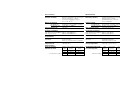
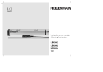
Instrucciones de montaje Mounting Instructions LB 302 LB 382 unisección Single-Section 4/2013 Indice Contents Página 4 Elementos suministrados Page 4 Items Supplied 6 Indicaciones para el montaje 6 Mounting Configuration Montaje 7 Trabajos preparatorios del montaje 8 Configuración de la salida del cable 9 Posición de la marca de referencia LB 302/LB 382 10 Dimensiones 12 Tolerancias de montaje 13 Sujeción de la regla 14 Comprobación de la regla 15 Trabajos finales del montaje 16 Compensación de errores lineales 17 Tensar la cinta de medida 18 Medidas de protección Mounting 7 Preparatory Work 8 Configuring the Cable Outlet 9 Reference Mark Position LB 302/LB 382 10 Dimensions 12 Mounting Tolerances 13 Securing the Encoder 14 Checking the Encoder 15 Final Steps 16 Linear Error Compensation 17 Tensioning the Scale Tape 18 Protective Measures Conexión eléctrica 19 LB 302/LB 302 C 21 LB 382/LB 382 C Electrical Connection 19 LB 302/LB 302 C 21 LB 382/LB 382 C Datos eléctricos 20 LB 302/LB 302 C 22 LB 382/LB 382 C Electrical Data 20 LB 302/LB 302 C 22 LB 382/LB 382 C Datos mecánicos 23 LB 302/LB 302 C 23 LB 382/LB 382 C Mechanical Data 23 LB 302/LB 302 C 23 LB 382/LB 382 C 2 Advertencias Warnings Atención: El montaje y la puesta en marcha deben ser realizados por un especialista cualificado, observando las prescripciones locales de seguridad. Conectar o desconectar el conector sólo en ausencia de tensión. El accionamiento no debe estar en marcha durante el montaje. Note: Mounting and commissioning is to be conducted by a qualified specialist under compliance with local safety regulations. Do not engage or disengage any connections while under power. The system must be disconnected from power! Dimensiones en mm Dimensions in mm 3 Elementos suministrados/Cable de conexión Items Supplied/Connecting Cable PF (2x) IIIIIIIIOIIIIIIOIIIIIIIIIIIIIIII IIIIIIIIOIIIIIIOIIIIIIIIIIIIIIII IIIIIIIIOIIIIIIOIIIIIIIIIIIIIIII IIIIIIIIOIIIIIIOIIIIIIIIIIIIIIII IIIIIIIIOIIIIIIOIIIIIIIIIIIIIIII IIIIIIIIOIIIIIIOIIIIIIIIIIIIIIII IIIIIIIIOIIIIIIOIIIIIIIIIIIIIIII IIIIIIIIOIIIIIIOIIIIIIIIIIIIIIII IIIIIIIIOIIIIIIOIIIIIIIIIIIIIIII IIIIIIIIOIIIIIIOIIIIIIIIIIIIIIII IIIIIIIIOIIIIIIOIIIIIIIIIIIIIIII IIIIIIIIOIIIIIIOIIIIIIIIIIIIIIII IIIIIIIIOIIIIIIOIIIIIIIIIIIIIIII Elementos suministrados Carro marca de referencia S1) Pieza de conexión A Tapón PF (repuesto) 1) en LB 302/LB 382 4 Items supplied Reference mark slider S1) Connecting piece A Plugs PF (replacement) 1) with LB 302/LB 382 a) b) c) ID 772141-01 Pedir por separado: a) Cable adaptador b) Cable de conexión correspondiente c) Galga de montaje Order separately: a) Adapter cable b) Matching connecting cable c) Mounting gauge 5 Indicaciones para el montaje 58 Escoger un lugar de montaje en el que el cabezal no pueda en ningún caso chocar con los extremos finales. Mounting Procedure 216 Choose a mounting position to ensure that the scanning unit cannot touch the end sections. Escoger una posición de montaje en la que los labios estén protegidos frente a posibles fuentes de contaminación. 6 En montaje vertical, extraer el tornillo de drenaje si no se usa aire comprimido. When mounting vertically, remove the drain screw if compressed air is not used. Mount with sealing lips facing away from possible sources of contamination. Trabajos preparatorios del montaje Preparatory Work Soltar ligeramente los tornillos de transporte del cabezal. Retirar la grapa de transporte. Loosen screws on shipping braces slightly. Remove the shipping brace clip. R 2. 1. Atornillar el cable adaptador (1 Nm), configurándolo de tal manera que el radio R de curvatura no sea inferior al permitido (ver datos técnicos). Md = 1 Nm Screw on the adapter cables (1 Nm). Configure the cable such that the bending radius R is not smaller than permissible (see Specifications). 7 Configuración de la salida del cable Changing the Cable Outlet Proteger la electrónica frente a cargas electrostáticas. Un brazalete puesto a tierra asegurará la protección durante la manipulación. Destornillar la tapa y, en caso necesario, el kit del cable. 2. Md = 1 Nm 4. 3. 180° Inclinar la pletina impresa con cuidado hacia abajo, extraerla y girarla 180 grados. Insertar primero la pletina por la parte del conector. ¡No pillar los hilos! 8 Detach the cover and (if necessary) the adapter cables. 3. 5. 1. 2. Protect the electronics from accumulating electrostatic charge. A grounded bracelet can ensure protection during handling. 1. Tilt the printed circuit board down carefully, pull it out and rotate it by 180°. Insert board connector side first. Do not pinch the wires. A continuación atornillar nuevamente la tapa y el kit del cable (1 Nm). Then attach cover and adapter cables again (1 Nm). Posición de la marca de referencia LB 302/LB 382 50 50 50 La marca de referencia puede activarse en cualquier taladro de montaje y en pasos n x 50 mm. 50 50 50 50 Reference Mark Position LB 302/LB 382 50 50 50 /2 ML 58 A reference mark can be activated at any mounting hole and at intervals of n x 50 mm therefrom. Tal como se suministra, la marca de referencia se activa en la mitad del recorrido de medida ML. As delivered, the reference mark is activated at the midpoint of the measuring length ML. RM R S RM RM Indique la posición de la marca de referencia deseada fijando la etiqueta RM en la carcasa. Cuidadosamente inserte el carro de marca de referencia rojo S a través de los labios de protección y mueva el selector R a la posición adecuada. Indicate the desired reference mark position by affixing the RM label on the housing. Carefully insert reference mark slider through the sealing lips and move the selector plate to the desired position. 9 Dimensiones Dimensions, Standard Version mm Tolerancing ISO 8015 ISO 2768 - m H < 6 mm: ±0.2 mm ML + 276 88 0.05 0.3 0.1 F 25 7 76±0.2 50 k 25 SW3 28 50 M5 (n x 200) ±0.15 k 98 80±0.15 k 200±0.15 d (168) k 0.3 F 18 40 25 40±0.2 r k 105 5 F = Guía de la máquina = Dimensiones requeridas usuario = Conexión de aire comprimido 160 40.08 80 0 40.04 10 0.1 F 8.5 25 ML/2 ML 58±2 17 35 s 85 58.5 63 d c = Posición de marca de F = Machine guideway referencia LB 302/LB 382 = Required mating = Posición de marca de dimensions referencia LB 302C/LB 382C = Compressed air inlet = Comienzo recorrido medida ML = Reference mark position LB 302/LB 382 = Reference mark position LB 302C/LB 382C = Start of measuring length ML Dimensiones, Versión reflejada Dimensions, Mirror-Imaged Version mm Tolerancing ISO 8015 ISO 2768 - m H < 6 mm: ±0.2 mm ML + 276 50 88 0.05 0.3 0.1 F 25 7 76±0.2 SW3 k 25 28 50 M5 168 (n x 200) ±0.15 200±0.15 k d k (98) 80±0.15 0.3 F k ML/2 ML 128±2 k 35 5 40.08 80 0 40.04 F = Guía de la máquina = Dimensiones requeridas usuario = Conexión de aire comprimido 40 25 40±0.2 r 160 s 0.1 F 8.5 105 17 25 85 58.5 18 63 d c = Posición de marca de F = Machine guideway referencia LB 302/LB 382 = Required mating = Posición de marca de dimensions referencia LB 302C/LB 382C = Compressed air inlet = Comienzo recorrido medida ML = Reference mark position LB 302/LB 382 = Reference mark position LB 302C/LB 382C = Start of measuring length ML 11 Tolerancias de Montaje Mounting Tolerances 0.1 // 0.1 // 0.1 F 10±0.3 k // 0.1 79±0.3 k 62±0.3 k // 0.3 F 0.05 // 0.1 F 45±0.3 k 15±0.3 k Posibilidades de montaje y tolerancias F = Guía de la máquina = Dimensiones requeridas usuario Mounting possibilities and tolerances F = Machine guideway = Required mating dimensions Es posible el montaje horizontal. A horizontal mounting attitude is possible. 12 25±0.2 k Sujeción de la regla Mounting M6 (M5) 50 76 +2 ML ISO 4762 M6 (ISO 4762 M5) M6 (M5) 40 25 Drill and tap fixing holes. Remove paint from mounting surface. ISO 4762 M6 (ISO 4762 M5) 35 ISO 4032 M6 ISO 4762 M6 Fijar la regla. No apretar fuertemente los tornillos. Secure the encoder. Attach screws loosely. Separar el seguro de transporte del cabezal y extraerlo. Slide shipping braces away from scanning unit and remove them. 8 Mecanizar los taladros y las roscas. La superficie de montaje debe estar libre de pintura. 80 ISO 7092 6 (ISO 7092 5) ISO 4762 M5 Posibilidad de montaje en la tapa del cabezal. No apretar fuertemente los tornillos. Mounting possibility on the cover of the scanning unit. Attach screws loosely. 13 Comprobación de la regla Checking the Encoder 0.3 // Número de puntos de medida: hasta ML 840: 2 x hasta ML 1740: 3 x hasta ML 3040: 4 x. F M6: Md = 8 Nm M5: Md = 5 Nm Verificar el paralelismo con la guía de la máquina. Posición de verificación en los extremos. Demás posiciones de verificación en intervalos regulares. Number of measuring points: Up to ML 840: 2 Up to ML 1740: 3 Up to ML 3040: 4. Check parallelism to machine guideway F. Gauging position at the ends. Further gauging positions at regular intervals. .1 // 0 1±0.3 M6 (M5) ID 772141-01 M5 Ajustar la distancia de trabajo con la regla de montaje (ID 772141-01). Apretar los tornillos uniformemente: M5: 5 Nm; M6: 8 Nm. 14 Set the scanning gap with the mounting gauge (ID 772141-01). Tighten the screws evenly: M5: 5 Nm; M6: 8 Nm. Trabajos finales del montaje Final Steps W Verificar la resistencia eléctrica entre la carcasa del conector y la regla: Valor nominal: 1 max. Check the shielding by measuring the resistance between connector housing and scale. Desired value: 1 max. Verificar las tolerancias de montaje y el funcionamiento del sistema de medida. Check mounting tolerances and functioning of encoder over the entire traverse range. 15 Compensación de errores lineales Linear Error Compensation Laser F 200µm 0.000 A 0 B 1m 2m 3m C L 200µm HEIDENHAIN HEIDENHAIN F 200µm LB 0.084 A 0 B 1m 2m 3m C L 200µm Puede efectuarse una compensación de un error lineal de hasta ± 100 µm/m sobre la longitud total de medida mediante el tensor de la cinta. HEIDENHAIN A linear error compensation of up to ± 100 µm/m can be applied to the entire measuring length with the tape tensioning device. Colocar un sistema de comparación (p.ej., interferómetro láser) en el plano de la pieza y medir la máquina. Set up a comparator system (such as a laser interferometer) in the workpiece plane and measure the machine tool. PF XK K µm = X K m Quitar el tapón PF. 16 Remove plug PF. Cálculo del valor de corrección K: medir la distancia XK, y multiplicar por el valor LK del protocolo de calibración. L K µm/m Calculate compensation value K: measure distance XK and multiply with linear compensation value LK (from measurement of machine). Tensar la cinta de medida Tensioning the Scale Tape PF 2.125 A B C HEIDENHAIN Tensar la cinta hasta que la visualización muestre el valor calculado anteriomente. Increase the tape tension until the display shows the value previously calculated. Ahora colocar de nuevo el tapón PF. Now replace plug PF. 17 Medidas de protección Protective Measures ID 226270-02 7 10 l/min 1 ± 0.2 bar 1±0.1 Nm Donde exista un importante peligro de contaminación se recomienda instalar sobre una regla una tapa adicional con una junta entre ésta y la superficie de montaje. If there is significant danger of contamination, fit a protective cover over the encoder with a seal between it and the mounting surface. Aire comprimido: 1 bar sólo a través del conector. Usar sólo aire limpio y seco. Compressed air: 14.5 psi only via connecting piece. Use only clean, dry air. Connection of compressed air at scanning unit. Compressed air unit available as accessory. Conexión del aire comprimido a las carcasas finales de la regla. Connect compressed air at scale end sections. DA 400 Conexión del aire comprimido al cabezal. Unidad de aire comprimido suministrable como accesorio. 18 Conexión eléctrica LB 302/LB 302 C Electrical Connection Conector 9 polos HEIDENHAIN 9-pin connector HEIDENHAIN LB 302/LB 302 C Conector Sub-D de 9 polos 9-pin connector D-Sub 1 2 5 6 7 8 3 4 6 1 8 3 9 5 7 2 5V 0V I1 I2 I0 + – + – + – UP UN verde Green amarillo Yellow azul Blue rojo Red gris Gray rosa Pink marrón Brown blanco White Carcasa Housing Carcasa Housing 9 Blindaje externo Ext. shield Blindaje interno Int. shield 4 blanco/marrón White/Brown Fuentes de interferencias Noise sources Para información general eléctrica, véase el catálogo de HEIDENHAIN For general eletrical information, refer to the HEIDENHAIN brochure 19 Datos eléctricos LB 302/LB 302 C Electrical Data LB 302/LB 302 C Tensión de alimentación Señales de salida DC 5 V ± 0,25 V/100 mA (sin carga) Power supply Output signals 5 V ± 0.25 V DC/100 mA (with no load) 360° el. I1 0 90° el. 0 0 Señales incrementales Amplitud de la señal con carga 1 k Señal marca de referencia Amplitud de la señal con carga 1 k Longitud del cable a la electrónica subsiguiente 20 2 señales sinusoidales I1 y I2 I1: 7 hasta 16 µAPP I2: 7 hasta 16 µAPP Uno (LB 302) o varios (LB 302 C) picos de señal I0 I0: 2 hasta 8 µA (componente útil) Máx. 30 m 360° el. I1 0 90° el. I2 0 I0 0 Incremental signals Signal amplitude with 1 k load Reference mark signal I2 I0 2 sinusoidal signals I1 and I2 I1: 7 to 16 µAPP I2: 7 to 16 µAPP One (LB 302) or several (LB 302 C) signal peaks I0 I0: 2 to 8 µA (usable component) Signal amplitude with 1 k load Cable length to subsequent Max. 30 m electronics Conexión eléctrica LB 382/LB 382 C Electrical Connection Acoplamiento de 12 polos HEIDENHAIN 12-pin HEIDENHAIN coupling Conector 12 polos HEIDENHAIN 12-pin HEIDENHAIN connector 5 6 8 A LB 382/LB 382 C 1 3 B 4 R + marrón – verde + gris – rosa + rojo – negro Brown Green Gray Pink Red Black 12 5V UP marrón/ verde Brown Green La línea del sensor está internamente conectada con la línea de alimentación. Blindaje situado en la carcasa. 10 0V UN blanco/ verde White Green 2 5V Sensor azul 11 0V Sensor blanco Blue White 9 libre Vacant / 7 libre Vacant violeta / libre Vacant amarillo Violet Yellow The sensor line is internally connected to the supply line. Shield is on housing. Fuentes de interferencias Noise sources Para información general eléctrica, véase el catálogo de HEIDENHAIN For general eletrical information, refer to the HEIDENHAIN brochure 21 Datos eléctricos LB 382/LB 382 C Electrical Data Tensión de alimentación Power supply DC 5 V ± 0,25 V/150 mA (con resistencia terminal Z0 = 120 ) Señales de salida Señales incrementales Amplitud de la señal Señal marca de referencia Amplitud de la señal Longitud del cable a la electrónica subsiguiente 22 LB 382/LB 382 C 5 V ± 0.25 V DC/150 mA (with terminating resistor Z0 = 120 ) Output signals 2 señales sinusoidales A y B A aprox. 1 VPP con resistencia terminal Z0 = 120 B aprox. 1 VPP con resistencia terminal Z0 = 120 Uno (LB 382) o varios (LB 382 C) picos de señal R R aprox. 0,4 V (coomponente útil) con resistencia terminal Z0 = 120 Máx. 150 m Incremental signals Signal amplitude 2 sinusoidal signals A and B A approx. 1 VPP with terminating resistor Z0 = 120 B approx. 1 VPP with terminating resistor Z0 = 120 Reference mark signal One (LB 302) or several (LB 302 C) signal peaks R Signal amplitude R approx. 0.4 V (usable component) with terminating resistor Z0 = 120 Cable length to subsequent Max. 150 m electronics Datos mecánicos Estándar de medida Marcas de referencia LB 302/LB 382 LB 302 C/LB 382 C Velocidad máxima de desplazamiento Mechanical Data Graduación AURODUR sobre cinta de acero Período de división P = 40 µm Coeficiente de dilatación térmica therm 10 · 10–6 K–1 Cada 50 mm, seleccionable con placas Codificadas con 2000 x P 120 m/min Measuring standard Reference marks LB 302/LB 382 Every 50 mm, selectable with plates LB 302 C/LB 382 C Distance-coded with 2000 x P Max. traversing speed Aceleración admisible máx. vibración (55 hasta 2000 Hz) 300 m/s2 (EN 60 068-2-6) 300 m/s2 (EN 60 068-2-27) máx. choque (11 ms) AURODUR graduation on steel tape Grating period P = 40 µm Thermal expansion coefficient therm 10 ppm/K 120 m/min (4724 ipm) Permissible acceleration Max. vibration (55 to 2000 Hz) 300 m/s2 (IEC 68-2-6) 300 m/s2 (IEC 68-2-27) Max. shock (11 ms) Fuerza requerida para el desplazamiento 15 N Required moving force 15 N Tipo de protección (EN 60 529) IP 53 si ha sido instalado según este modo de empleo IP 64 con conexión de aire comprimido Protection type (IEC 529) IP 53 when installed according to mounting instructions IP 64 with compressed air Temperatura de trabajo Temperatura de almacenamiento 0 hasta 50 °C –20 hasta 70 °C Operating temperature Storage temperature 0 to 50 °C (32 to 122 °F) –20 to 70 °C (–4 to 158 °F) Radio de curvatura admisible del cable Diámetr Para curvatura Para curvatura ocable flexible rígida Permissible bending radii for connecting cable Cable diameter For frequent flexing For rigid configuration 6 mm R 75 mm R 20 mm 6 mm R 75 mm R 20 mm 8 mm R 100 mm R 40 mm 8 mm R 100 mm R 40 mm con manguera metálica 10 mm R 75 mm R 35 mm R 75 mm R 35 mm with armor tubing 10 mm 23 ���������������������������� �������������������������������� ������������������������ � ������������� � ������������� �������������������������� ����������������� � ���������������� ����������������� � ���������������� ���������������������������������������� ����������� � ���������������� ���������������������������������������� �������������� � ���������������� ������������������������������������ ��������������� � ���������������� ��������������������������������� �������������� � ���������������� ������������������������������������������� ����������������� *I_673176-53* 673176-53 · Ver02 · Printed in Germany · 4/2013 · H