1
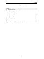
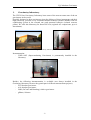
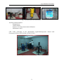
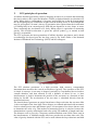
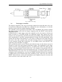
FG5
Absolute Gravimeter
José Manuel Serna, Pedro Vaquero, Sergio Sainz-Maza
Marta Calvo, B. Córdoba, Javier López
Carmen López, J.A.López Fernández
INFORME TÉCNICO IT - OAN 2012 - 01
Contents
Contents
Contents ............................................................................................................................. I
1. Gravimetry laboratory. ............................................................................................. 1
2. FG5 principles of operation. ..................................................................................... 3
3. Hardware components and function. ........................................................................ 5
3.1. The dropping chamber ....................................................................................... 5
3.2. The service ring ................................................................................................. 8
3.3. The dropper controller ....................................................................................... 9
3.4. Interferometer .................................................................................................. 10
3.5. Superspring ...................................................................................................... 11
3.6. Laser system .................................................................................................... 12
4. FG5 Setup ............................................................................................................... 13
5. Specifications ......................................................................................................... 15
6. Applications ............................................................................................................ 15
7. References .............................................................................................................. 16
Appendix. About the installation procedure (Spanish) .................................................. 17
-I-
Contents
-II-
Fg5 Absolute Gravimeter
1.
Gravimetry laboratory.
The CDT-Yebes Gravimetry Laboratory hosts some of the most accurate state of the art
gravimeters in the world.
Specially designed to host gravimeters given the delicacy of these instruments and their
high sensitivity, presents a very controlled thermal behavior (double chamber with air
conditioning system in the external one) and structural behavior (isolated concrete
pillars). We offer this laboratory for future RICAGs (regional AG comparisons, up to 6
instruments).
fig. 1 Gravimetry laboratory
Instrumentation:
- GWR OSG (Superconducting Gravimeter) is permanently installed in the
laboratory.
fig. 2 Observatory Superconducting Gravimeter
Besides, the following instrumentation is available (not always installed in the
Gravimetry laboratory because they participate in different measurement projects).
- FG5 absolute gravimeter.
- A10 absolute gravimeter.
- L&R (LaCoste and Romberg) relative gravimeter.
- gPhone, Scintrex.
-1-
Fg5 Absolute Gravimeter
fig. 3 Gravimeters (FG5, A10 and Scintrex)
Auxiliary instrumentation.
- Seismometers.
- GNSS stations.
- H maser for clock measurement/calibration.
- Maintenance stuff.
CDT Yebes participate in the international organizations/projects related with
Gravimetry Science (GGP, AGrav, ECAG, ICAG).
fig. 4 GWR-OSG and FG5 installed in Yebes
-2-
Fg5 Absolute Gravimeter
2.
FG5 principles of operation.
A ballistic absolute gravimeter works by dropping an object in a vacuum and measuring
the time it takes to fall a specified distance. Galileo recognized that the acceleration of a
freely falling body is independent of its mass, and legend has it that he demonstrated
this by dropping objects of different weight from the leaning tower of Pisa (though this
may be apocryphal). Newton’s theory of gravitation also required that the acceleration
of a falling body in an external gravity field did not depend on its size, shape, or mass.
Thus, measuring the acceleration of a freely falling object is equivalent to measuring
gravity. This freefall acceleration is given the special symbol, g, to remind us that
gravity is responsible.
The FG5 represents the latest generation of ballistic absolute gravimeters and is based
on technology developed over the last forty years by Dr. James Faller of the National
Institute of Standards and Technology (NIST) and his colleagues.
fig. 5 FG5 installed at Yebes
The FG5 absolute gravimeter is a high precision, high accuracy, transportable
instrument that measures the vertical acceleration of gravity. The operation of the FG5
is simple in concept: A test mass is dropped vertically by a mechanical device inside a
vacuum chamber, and then allowed to fall a distance of about 20 cm. A laser
interferometer is used to determine the position of the test mass as a function of time
during its freefall. The acceleration of the test mass is calculated directly from the
measured trajectory.
The interferometer generates an optical interference fringe each time the test mass falls
½ the wavelength of the laser light. These fringes are counted and timed with an atomic
clock to obtain precise time and distance pairs. A least-squares fit to these data are used
to determine the value of g. This method of measuring gravity is absolute because the
determination is purely metrological and relies solely on standards of length and time.
The distance scale is given by a frequency stabilized helium neon (HeNe) laser used in
the interferometer. A rubidium atomic time-base provides the accurate time scale. The
value of gravity obtained with the FG5 can be used without the loop reductions and drift
-3-
Fg5 Absolute Gravimeter
corrections normally required when using relative instrumentation. With the FG5, the
absolute gravity value is determined and reported immediately.
Figure 6 shows how gravity is measured with an FG5. A test body, containing a corner
cube retro-reflector, is dropped from the top of the dropping chamber. The laser light is
split to reflect off the falling corner cube and a fixed corner cube which serves as a
reference. The mass accelerates to the bottom of the chamber, and the raw fringe signal
is detected by the photodiode as the dropped object falls. The optical fringes in the raw
fringe signal are timed to create calibrated time and distance pairs. The lower part of the
figure demonstrates the increase in the fringe signal frequency as the test body
accelerates.
fig. 6 Direct measurement of Absolute g
-4-
Fg5 Absolute Gravimeter
3.
Hardware components and function.
The FG5 System consists of a Dropping (or Vacuum) Chamber, Interferometer Base,
Superspring, Laser, System Controller, and Electronics. The test mass is allowed to
free-fall inside the evacuated Dropping Chamber. The Interferometer Base (or “IB”) is
used to monitor the position of the freely-falling test mass. The Superspring is an active
long-period isolation device used to provide an inertial reference for the gravity
measurement. The System Controller (computer) allows a flexible user interface,
controls the system, acquires data, analyzes data, and stores the results. The Electronics
provides high accuracy timing necessary for the measurement and provides system
servo control. Each component is discussed in detail below.
fig. 7. FG5 subsystems
3.1.
The dropping chamber
The Dropping Chamber is an evacuated chamber which contains a drag-free cart which,
in turn, houses the test-mass/corner-cube. Next figure shows a schematic. A drive
mechanism is used to drop, track, and catch the test mass inside the drag-free cart. Laser
light passes through a window in the bottom of the Dropping Chamber to the corner
cube (inside the test mass), and is then reflected back down through the window to the
interferometer.
-5-
Fg5 Absolute Gravimeter
fig. 8 FG5 dropping chamber (front view)
-6-
Fg5 Absolute Gravimeter
fig. 9. FG5 dropping chamber (side view)
The drag-free cart is used to lift, drop, and catch the test mass. The term “drag-free”
refers to the fact that though the chamber is evacuated, there are still some residual air
molecules. The cart effectively pushes these molecules out of the way of the test mass,
which is falling inside the cart. In addition to reducing drag, the cart also reduces
magnetic and electrostatic forces on the test mass.
The test mass contains a retro-reflective corner-cube surrounded by a support structure
which is balanced at the optical center of the corner-cube. The corner-cube is a threesurface mirror which has the special optical property that the reflected beam is always
parallel to the incident beam. In addition, the phase shift of the reflected beam is
virtually constant with respect to any slight rotation or translation of the corner cube
around its optical center. When in contact with the cart, the test mass is supported by
three spherical feet (or “balls”) that fit and orient it to “vees” in the cart.
The drive mechanism is a support structure inside the dropping chamber on which the
cart/drag-free chamber travels up and down, and is driven by a DC servo motor. The
cart is attached to a belt that is driven up and down by a shaft attached to the motor. The
motor is located outside of the chamber is connected to the shaft via a ferrofluidic
feedthrough (this device allows the vacuum to be maintained inside the chamber while a
shaft rotates through the wall). The motor also turns an optical shaft encoder that
-7-
Fg5 Absolute Gravimeter
provides accurate information to the dropper controller on the position and velocity of
the pulley.
At the beginning of a drop, the cart accelerates downwards with an acceleration greater
than g allowing the test mass to begin freefall. Once a certain separation (typically about
3 mm) between the cart and the test mass is reached, the cart slowsdown and then tracks
the test mass, maintaining a constant separation of a few millimeters. Finally, at the
bottom of the drop, the cart gently catches the test mass and decelerates to a stop.
The tracking during the drop is accomplished by a sophisticated servo system that
works as follows: By keeping track of the cart position using a shaft encoder on the belt
drive pulley, and using the interferometer (fringes) to establish the object position, the
distance between the cart and the mass can be derived. During freefall, this separation is
maintained at a constant distance by using a servo-motor drive system to control the cart
inside the Dropping Chamber. Because there is essentially no relative motion between
the test mass and the drag-free chamber, the effects of residual air drag are eliminated.
fig. 10. Cart drag-free chamber
3.2.
The service ring
The Service Ring is at the base of the Dropping Chamber. It provides connections and
mounting for the following:
• A bellows-type vacuum valve for the initial evacuation of the vacuum system
• A Ferrofluidic rotary vacuum feedthrough which connects the motor shaft to the cart
drive mechanism
• A servo motor/rotary shaft encoder assembly which moves the cart and senses its
position
• An ion pump, mounted on a 2¾” Conflat flange, which maintains the vacuum once the
chamber has been evacuated by the roughing pump
• Spare 2¾” Conflat and Mini-Conflat flanges are blanked off, and can be used for
additional vacuum accessories
-8-
Fg5 Absolute Gravimeter
fig. 11. FG5 service ring
3.3.
The dropper controller
The dropper controller is the servo circuit that controls the motor that drives the cart.
Located in the SIM (please the SIM User’s Manual for more information), it is also the
interface between the user and the dropping chamber.
The controller can be operated in two modes: OSC and DROP. The operator controls
the status of these modes and the dropper triggering with the RESET switch and the
TRIGGER switch.
In DROP mode, a single trigger causes the controller to drive the motor to lift the cart
(and test mass) to a specified height. An additional trigger then initiates the drop
sequence: the cart pulls away with an acceleration greater than g, and then tracks the test
mass (maintaining a specified separation distance) during free-fall, and finally softly
catches the test mass at the bottom. If a TTL pulse is entered into EXT TRIG this will
also cause a lift, and a separate pulse will cause the drop. These are normally supplied
by the computer during data acquisition. To exit DROP mode, press RESET. The
controller is now insensitive to triggers.
OSC (oscillation) mode is used to slowly raise and lower the cart (the object is never in
freefall) to create slow and constant interference fringes. The magnitude of this fringe
signal is used for system alignment purposes. To initiate OSC mode, first make sure the
dropper is un-travel-locked, and the press OSC. You should see the position LEDs on
the front of the SIM indicate a slow movement of the cart. To stop OSC mode, press the
TRIGGER button at any time. The cart will automatically stop at the bottom of the next
oscillation cycle (Alternatively, you can press DROP, and this will place the controller
in DROP mode at the bottom of the next oscillation cycle). Take care not to hit the
RESET button directly, as this will immediately (and roughly!) drop the test mass and
cause excessive wear on the ‘balls’ and ‘vees’.
-9-
Fg5 Absolute Gravimeter
3.4.
Interferometer
fig. 12. Schematic of FG5 interferometer
The optical fiber directs the laser light from the laser head to the interferometer base. At
the input of the interferometer, a lens collimates the light from the optical fiber. It is
then directed to Beamsplitter #1, where it is split into the test beam and the reference
beam. The reference beam is split again at Beamsplitter #2 and travels to the Avalanche
Photo Diode (APD) and the fringe viewer. Note that the path length of the reference
beam remains constant.
The test beam is reflected vertically at beamsplitter #1, and passes through a
compensator plate and a window in the bottom of the Dropping Chamber. It is then
reflected back down by the corner cube in the test mass. The test beam returns through
the window, the compensator plate, and passes down through the interferometer base to
the Superspring. The test beam passes through the top window of the Superspring
chamber to the corner cube in the Superspring mass. From here, the test beam is
reflected back up out of the Superspring and into the interferometer base, where it
reflects off Mirror #1 (or the “pick off mirror”), passes through the translator plate
(“twiddler”), reflects off Mirror #2, and is recombined with the reference beam at
Beamsplitter #2.
fig. 13. Interferometer diagram
-10-
Fg5 Absolute Gravimeter
This interferometer is of the Mach-Zender type, with a fixed (reference) arm and a
variable (test) arm. During a drop, the motion of the test mass affects the path length of
the test beam. The interference fringes which result from the recombination of the test
beam and the reference beam provide an accurate measure of the motion of the test
mass relative to the mass suspended on the Superspring.
The two beams are recombined at Beamsplitter #2 and then split again. One set is
focused by a lens to strike the detector (APD). The interference fringes are converted to
an Analog signal and a Transistor-Transistor Logic (TTL) signal which is transmitted to
the time interval analyzer card in the system controller.
The other recombined beam set travels horizontally until it reaches the attenuator plate
(“rattler”). This beam is split yet again and reflects between the beamsplitter coating and
the uncoated side of the attenuator plate. Three beams of decreasing intensity emerge
from the coated side. The first and brightest of these beams travels horizontally into the
fringe viewer. The second and third beams are deflected vertically by a mirror. A flag in
front of the mirror blocks the second beam, allowing the third (dimmest) beam to exit
the interferometer where it is reflected off Mirror #3 and enters the collimating
telescope.
3.5.
Superspring
The Superspring is a long-period, active vertical isolator used to compensate for small
vertical motions of the first beam splitter. The Superspring has a short (20 cm)
mainspring with a natural period of about 1 second. The mainspring is contained in a
support housing (also supported by springs) that is actively servo-controlled to track the
Superspring mass at the end of the mainspring. The result is a long-period (30-60
second, or 16-30 mHz), spring-mass system that isolates against ground motions
occurring at a higher frequency than its own enhanced natural frequency. This insures
that any change in the length of the test beam is due only to the acceleration of the
dropped object.
fig. 14. Superspring schematic
-11-
Fg5 Absolute Gravimeter
3.6.
Laser system
The FG5 employs a stabilized helium-neon laser (Winters Electro-Optics Model 100
iodine stabilized laser) to provide an accurate and stable wavelength used in the
interferometric measurement system. This laser is a primary standard for the definition
of the meter at the Bureau International des Poids et Measures (BIPM) in Sevres,
France. It is a highly stabilized frequency standard (trivially converted to a distance
10
standard in a vacuum) having an absolute frequency accuracy of 1 part in 10 (50 kHz).
All models of lasers need to be warmed up and reach thermal equilibrium before gravity
data are acquired. As a rule of thumb, it is best to power on the laser the night before
measurements, if possible. At a minimum the lasers should be one at least 1-4 hours for
good results.
Again, regardless of the laser model, the light is always linearly polarized and reaches
the interferometer via a single mode, polarization-maintaining fiber optic cable. The
fiber polarization is set to match that of the laser light at the factory – under normal
operations, it is never necessary to adjust the rotation at the input of the fiber.
The light enters the fiber optic cable via a 5-axis mount that focuses the light down to a
diameter of a few microns. This adjustment is also done at the factory and is extremely
sensitive. The laser light exits the fiber and diffracts at a well defined angle to avoid
back-reflections. A collimating assembly is attached to the output of the fiber and is
adjusted such that the final beam is well collimated at approximately 8 mm. Again, note
that this collimation adjustment is performed at the factory, is extremely sensitive,
critical for the gravity measurement, and should not need to be adjusted.
Finally, because the laser light is polarized, it is necessary to rotate the output of the
fiber about its axis so as to evenly split the laser power between the test and reference
beams (horizontally polarized light is transmitted more efficiently into the reference
beam, while more vertically polarized light is transmitted in the test beam – the nominal
position is thus at about 45º). Again, this adjustment is performed at the factory and
should not need to be changed by the user.
-12-
Fg5 Absolute Gravimeter
4.
FG5 Setup
For more detailed description, please consult references.
Place electronics box approximately 1 m from measurement location
Check line voltage settings (especially for WEO laser)
Check that ion pump is powered on and operating correctly. Connect to reliable
AC power source.
Make sure the FG5 Power Supply AC & DC power is off
Make sure the WEO Controller switches (AC and HV) are set to OFF.
Turn FG5 Power Supply AC power on.
Place laser on stable surface, connect cables to WEO controller, turn on WEO
controller and enable HV. The laser should emit laser light within a minute or
so.
Place Superspring tripod at measurement location. Orient the line from the center
of the tripod to the bull’s eye level along a North-South axis.
Use tripod feet to center the bull’s eye level.
Measure and record the lower reference height
Place and lock Superspring in tripod with travel lock oriented towards bull’s eye
level
Level the Superspring tripod to the Superspring bubble levels
Remove Superspring dust cap
Place IB on top of Superspring with fiber optic oriented towards bull’s eye level
Assemble dropping chamber tripod
Place dropping chamber tripod onto IB with the small hole in the tripod oriented
towards the bull’s eye level.
Remove dust cap from IB
Place dropping chamber into dropping chamber tripod with the ion pump
oriented towards the beam-blocker side of the IB.
Place the dropping chamber tripod feet under the tripod and adjust them until
they are “just touching” the legs of the dropping chamber tripod
Turning each foot one turn counter-clockwise one turn at a time, lift the dropping
chamber two total turns
Fine tune the level of the dropping chamber.
If necessary, fine tune the level of the Superspring.
Measure and record the upper reference height
Un-travel lock the dropping chamber
(Verify DC power is OFF) Connect the cables from the electronics to
Superspring, IB, and dropping chamber.
Un-travel lock the Superspring
Turn on DC power
If necessary, Zero the Superspring
When spring motion has calmed down, enable Superspring Servo
Check and adjust (if necessary) beam verticality
Use Twiddler and lower mirror to maximize fringe signal (check with
oscilloscope and OSC mode)
Check and adjust (if necessary) beam verticality again
Place dropper in DROP mode
Verify that Rubidium clock has stabilized (RUB POWER light is steady ON)
Turn on Magma Box if necessary
-13-
Fg5 Absolute Gravimeter
Turn on laptop PC power
Turn computer power ON and set up software
Enter the total reference height and check all other parameters
Take data
Tear Down
Back up data (if applicable) and turn computer power OFF
Travel lock Dropper
Turn DC Power Off
Turn off laser HV and AC power
Turn AC Power off
Travel lock Superspring
Disconnect all cables (but get power to ion pump, and generally leave fiber optic
connected between laser and IB)
Unless shipping overseas, keep ion pump powered ON!
Remove dropper (double check it is travel locked)
Remove dropper tripod (and disassemble)
Remove IB from Superspring and place it and laser in shipping box
Remove Superspring (double check it is travel locked)
Pack Superspring tripod
-14-
Fg5 Absolute Gravimeter
5.
Specifications
6.
Applications
-15-
Fg5 Absolute Gravimeter
7.
References
[1] FG5Manual2007.pdf
[2] FG5PowerPoint.pdf
[3] FG5_brochure.pdf
[4] FG5-211 2010 Service Report.pdf
[5] workshop2010materialFG5.doc
-16-
Fg5 Absolute Gravimeter
Appendix. About the installation procedure (Spanish)
Pasos previos
• Elegir localización y buscar el Norte.
• Buscar 3 puntos cercanos de red AC (para la caja de electrónica, el controlador de la
bomba y el multímetro Fluke).
• Situar la caja de electrónica aproximadamente a 1 m del punto de localización.
• Comprobar que los voltajes de suministro son los correctos.
• Comprobar el funcionamiento correcto de la bomba iónica.
• Los siguientes interruptores deben estar apagados:
• Main AC power (trasera).
• Main DC power (trasera).
• Laser Main AC power y HV power (la llave).
• Si la bomba iónica está manteniendo el vacío del Dropper con la batería del
controlador de la bomba, desconectar el controlador (los tres interruptores AC, BAT y
HV, de derecha a izquierda), enchufarle a la red AC y volver a conectarlo (los tres
interruptores de izquierda a derecha).
• Situar el láser en el suelo, aproximadamente a 1 m del punto de localización. Situar la
fibra óptica en lugar seguro.
• Conectar el cable de Main AC power (trasera) a la red. Si utilizamos UPS: Conectar
UPS a red y el cable de Main AC power a la UPS.
• Encender los interruptores Main AC y DC power (trasera).
• Conectar los dos cables que van al Láser y encender el Láser para que alcance cuanto
antes su equilibrio térmico:
• Encender el interruptor Main AC Power del láser y la llave para HV.
• Seleccionar el pico de láser (normalmente el E).
• Colocar Servo Control en AUTO.
• Los demás controles deben estar siempre del siguiente modo:
• Meter Select: 1F.
• Gain: 1.
• Time Constant: 1.
• Body Temp Mode: TEMP.
• Meter: BIAS.
• Bias Voltage: Colocar en 0 V (meter).
• Dejar calentar al menos dos horas (o hasta que la temperatura se haya estabilizado)
antes de comenzar las observaciones.
Montaje del instrumento.
- Colocar la base, orientando la burbuja en la dirección N-S
-17-
Fg5 Absolute Gravimeter
-
Nivelar la base utilizando las 3 patas.
Medir la altura de referencia inferior, utilizando la regla micrométrica.
-
Limpiar bien la base y colocar encima el superspring, con el botón de bloqueo
mirando al lado del nivel esférico.
Fijarlo con las 3 sujeciones.
Nivelar los niveles del superspring.
-
Quitar la tapita.
Colocar encima el interferómetro, y poner el láser al lado.
La fibra óptica queda en la dirección N-S, encima de la burbuja
El ocular queda perpendicular a la dirección N-S.
Fijarlo con las 4 sujeciones. Apretar en diagonal.
-18-
Fg5 Absolute Gravimeter
-
Quitar la tapita.
Volver a nivelar la base.
Montar las patas de la segunda base. Apretarlas bien.
Colocar la segunda base (sin los pies) encima del interferómetro. El agujero debe
quedar mirando al lado del nivel esférico.
-
Colocar la cámara de caída encima de la segunda base.
La bomba iónica queda en la dirección del anteojo.
-
Fijarlo con las 3 sujeciones.
Desbloquear el Travel-Lock de la cámara de caída. Subir y bajar el carrito
manualmente con una llave allen.
-19-
Fg5 Absolute Gravimeter
-
Al transportar la cámara de caída, si la bomba iónica está manteniendo el vacío
del Dropper con la batería del controlador de la bomba, hay que desconectarlo
(de derecha a izq) enchufarle a la red AC y volver a conectarlo (de izq a dcha).
Comenzar a conectar los cables.
Dejar el cable del SS sin conectar, se conectará al final.
Conectar el láser para que empiece a calentarse (es lo que más tarda en alcanzar
la temperatura).
- Poner los pies bajo las patas y las almohadillas azules bajo los pies.
Una vez que los pies toquen las bolas blancas de nylon de las patas, elevar cada uno 1
vuelta y media, en sentido contrario a las agujas del reloj.
- Comprobar que están separadas las 2 partes, pasando un papel fino.
- Volver a nivelar en caso de ser necesario.
- Medir la altura de referencia superior, metiendo la regla por la hendidura.
-
-20-
Fg5 Absolute Gravimeter
Conexión de los cables
-
Comprobar que los cables de power/control del SS están bien conectados.
Lo mismo con los cables de power/control del DROPPER
-21-
Fg5 Absolute Gravimeter
-
Cables cámara vacío.
-
Cable de energía.
-22-
Fg5 Absolute Gravimeter
-
Cables láser.
-
Para empezar a calentar el láser (es el que tarda más en alcanzas su temperatura,
2 o 3 horas):
Panel trasero: AC on/DC on (En unos min se enciende la luz roja)
Panel delante: Power on + girar llave a la derecha
1. Meter Select 1F
2. Servo Control AUTO
3. Servo Control e
4. GAIN 1
5. TIME CONSTANT 1
6. BODY TEMP MODE TEMP
-23-
Fg5 Absolute Gravimeter
-
Cable fotodiodo.
-
Cable TTL.
-
Cable del reloj.
-24-
Fg5 Absolute Gravimeter
-
Cable de la temperatura.
-
Cables del ordenador.
-
Cable del SS.
-25-
Fg5 Absolute Gravimeter
-26-