1
MANUAL DE USO E INSTALACIÓN
INSTALLATION AND MAINTENANCE MANUAL
Sauna finlandesa
Finnish sauna
V.09/10
INDICE
Descripción.
Origen y evolución de la sauna . . . . . . . . . . . . . . . . . . . . . . . . . .Pag-1
Descripción general concepto sauna . . . . . . . . . . . . . . . . . . . . . .Pag-1
Materiales y componentes básicos . . . . . . . . . . . . . . . . . . . . . . .Pag-2
Detalle constructivo y de anclaje . . . . . . . . . . . . . . . . . . . . . . . . .Pag-3
Modelos disponibles. Capacidad y distribución . . . . . . . . . . . . . .Pag-3 a 5
Condiciones y precauciones previas a la instalación.
Condiciones del entorno a la sauna . . . . . . . . . . . . . . . . . . . . . . .Pag-6
Líneas de conexión para la sauna . . . . . . . . . . . . . . . . . . . . . . . .Pag-6
Cuadros de poténcias y acometidas eléctricas . . . . . . . . . . . . . .Pag-6
Proceso de montaje e Instalación.
Montaje de la cabina . . . . . . . . . . . . . . . . . . . . . . . . . . . . . . . . . . .Pag-7
Equipamiento interior. Montaje Accesorios . . . . . . . . . . . . . . . . . .Pag-7 a 11
Prolongaciones de fachada a techo . . . . . . . . . . . . . . . . . . . . . . .Pag-12
Conexionado eléctrico . . . . . . . . . . . . . . . . . . . . . . . . . . . . . . . . . .Pag-13
Equipos eléctricos.
Esquema eléctrico general opciones de conexión . . . . . . . . . . . .Pag-14,15
Cuadro de mandos Saunatherm, Saunatherm U y Microtherm . .Pag-16,17
. . . . . . . . . . . . . . . . . . . . . . . . . . . . . . . . . . . . . . . . . . . . . . . . . . .Pag-15
Calefactores S-33. . .W-25. . .SCA-45D . . . . . . . . . . . . . . . . . . . . . . . . . . .Pag-18 a 20
Equipo especial Bio Sauna-Vapor . . . . . . . . . . . . . . . . . . . . . . . . .Pag-23
Equipos opcionales.
Cromoterápia . . . . . . . . . . . . . . . . . . . . . . . . . . . . . . . . . . . . . . . . .Pag-21
Cromoterápia de Fibra Óptica cielo estrellado . . . . . . . . . . . . . . .Pag-22
Musicoterápia . . . . . . . . . . . . . . . . . . . . . . . . . . . . . . . . . . . . . . . .Pag-22
Equipo especila BIO . . . . . . . . . . . . . . . . . . . . . . . . . . . . . . . . . . .Pag-23,24
Calefactor oculto y equipos de dosificación.
Dosificación manual de agua . . . . . . . . . . . . . . . . . . . . . . . . . . . .Pag-25
Dosificación automática de agua . . . . . . . . . . . . . . . . . . . . . . . . .Pag-25
Dosificación automática de agua y esencias . . . . . . . . . . . . . . . .Pag-26
Aromaterápia múltiple . . . . . . . . . . . . . . . . . . . . . . . . . . . . . . . . . .Pag-26,27
Puesta en marcha y funcionamiento.
Normas de uso de la sauna . . . . . . . . . . . . . . . . . . . . . . . . . . . . . .Pag-29
Como debe realizarse la sesión de sauna . . . . . . . . . . . . . . . . . .Pag-29
Contraindicaciones . . . . . . . . . . . . . . . . . . . . . . . . . . . . . . . . . . . . .Pag-25
Uso de los aromas . . . . . . . . . . . . . . . . . . . . . . . . . . . . . . . . . . . . .Pag-26
Limpieza y desinfección de la cabina . . . . . . . . . . . . . . . . . . . . . .Pag-26
Posibles averías . . . . . . . . . . . . . . . . . . . . . . . . . . . . . . . . . . . . . .Pag-26
DESCRIPCION.
Origen y evolución del baño de sauna.
El baño de sauna tiene su origen secular en las zonas del Báltico. Su objeto era
inicialmente combatir las consecuencias de las bajas temperaturas que los
habitantes de la zona sufrían, sobre todo en la época invernal. Con el
transcurrir del tiempo y superada la necesidad de protegerse del clima propio
de la zona debido a los avances técnicos, la sauna se había convertido en un
ritual o especie de ceremonia familiar muy efectiva para alcanzar el bienestar y
relajación física y psíquica necesaria en toda sociedad moderna.
Hoy día, la sauna es considerada en los países que conforman esta zona,
principalmente FINLANDIA y SUECIA, como elemento esencial de toda
actividad cuyo fin sea encontrar ese bienestar físico. Es asímismo considerada
una terapia fundamental de relajacion mental.
Dadas estas particularidades, en estos países, y también en aquellos donde el
desarrollo social es alto, el uso de la sauna se ha ido extendiendo de forma
espectacular, hasta el punto en que, en algunas zonas, buena parte de las
viviendas están equipadas con este elemento terapéutico.
Como se ha visto, el objeto de la sauna es la relajación y el bienestar físico y
mental y, aunque tiene toda una serie de efectos positivos para el organismo,
su efecto principal no es la pérdida de peso, aunque siempre lo impulsa si se
acompaña de un régimen hipocalórico adecuado.
Efectos del baño de sauna sobre el organismo:
- Distensión nerviosa Relajación.
- Dilatación ramificaciones respiratorias Oxigenación.
- Vasodilatación periférica Estimulación de la circulación
sanguínea en extremidades.
- Elevación de la frecuencia cardíaca Estimula sist.circulatorio.
- Limpieza de toxinas de los poros Glándulas sudoríparas.
- Mejora de la elasticidad del tejido muscular y articulaciones
óseas.
pg.1
Descripción general concepto sauna.
En su origen, la sauna era una simple cavidad realizada en la superfície, en la
que se introducían piedras previamente calentadas al fuego para producir el
calor.
Posteriormente y con el desarollo de la técnica, se iniciaron las construcciones
de saunas en pequeñas casas de madera, siempre en el exterior. El calor se
producía a través de una chimenea tradicional interior a la sauna que, al fuego
calentaba las piedras, expulsando el humo por una salida directa.
Hoy día, la sauna finlandesa se ha ido enriqueciendo con los avances técnicos
de nuestro tiempo, de forma que ha sufrido importantes variaciones en su
construcción, las cuales se desarrollan en este manual.
La sauna finlandesa es, actualmente, un habitáculo vertebrado por una
estructura de madera tipo modular con material aislante en su interior y
recubierto por un revestimiento machiembrado. Está equipada con literas
o bancos y los accesorios
interiores pueden ser de lo
más variado y sofisticado.
El elemento esencial de la
sauna es el equipo eléctrico
que genera el calor, calentando el aire para provocar
una temperatura muy
elevada en su interior a la
vez que se obtiene un
nivel de humedad muy
bajo debido al efecto de
absorción de la madera.
La sauna se concibe de forma autónoma o independiente a la vivienda o local
en el que se encuentre. A su vez normalmente la mayoría de saunas son de
interior aunque se pueden construir también de exterior.
Tal como se ha podido adivinar, la sauna genera calor estrictamente seco,
reduciendo la humedad del aire al calentarse por defecto absorción. Con lo cual
es un error asociar la sauna al vapor,fenómeno que se produce expresamente
en los “BAÑOS DE VAPOR”, cuyo efecto y concepción son esencialmente
distintos.
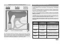
Sistema de convección y renovación de aire
75 - 100 °C
60 - 100 °C
Materiales y componentes básicos sauna.
40 - 60 °C
Los materiales utilizados en el proceso de fabricación de la sauna determinan
en gran medida su buen funcionamiento y las prestaciones y funcionalidad
esperados.
Al igual que cualquier producto que se precie de su calidad y resultado óptimo
en su uso, los componentes de fabricación de la sauna finlandesa deben
cumplir una serie de requisitos cualitativos.
Por ello, en las siguientes líneas se detalla la relación de los materiales
utilizados en la fabricación de la sauna,así como los criterios selectivos que se
utilizan en su elección.
LA MADERA: Esta es la principal materia prima utilizada en la fabricación de la
sauna, y las características de este material, junto con el sistema de fabricación
y anclaje, configuran esencialmente LA CALIDAD de la misma.
La sauna incorpora distintas clases de madera en su fabricación, y cada una de
ellas debe cumplir unos requisitos concretos según sea la función que va a
desempeñar.
Entrada
aire.
DETALLE PROGRESION TERMICA
Salida
aire.
Tal como podemos apreciar en esta figura, cuando la sauna está en régimen
de uso, se produce en su interior una progresividad térmica escalada. Esta
escala se debe a la mayor ligereza del aire cuando aumenta la temperatura. A
su vez este sistema nos permite una renovación contínua del aire,
manteniendo una elevada temperatura en el interior de la sauna.
TIPO DE
MADERA
PIEZA/S
CARACTERISTICA/S
ESENCIALE/S
ABETO BALTICO
MACHIEMBRADO
ESTRUC.BANCOS
AROS-PERIMETRO
ESTRUC.MODULOS
RESISTENCIA CONTRASTE TERMICO
POROSIDAD.ABSORCION HUMEDAD.
CAPACIDAD AISLAMIENTO TERMICO.
RESISTENCIA CONTRA ROTURAS.
HEMLOCK
CANADA
MACHIEMBRADL
EXTERIOR
IGUALES CARACTERISTICAS
(MADERA SIN NUDOS)
ABBACHI SAMBA
BANCOS- LITERAS
CABEZALES,
VALLA PROTECC.
POROSIDAD. ESPONJOSIDAD.
RESISTENCIA A TRANSMISION
TERMICA. (MADERA SIN NUDOS)
TABLEROS
FIBRAS
REVESTIMIENTO
TRASERA-TECHO
RESISTENCIA Y DURACION
CAPACIDAD AISLAMIENTO TERMICO
pg.2
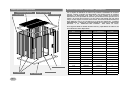
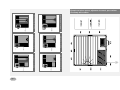
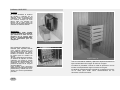
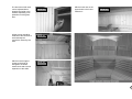
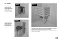
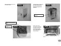
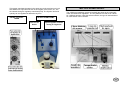
Detalle posición componentes.
N°6:MODULOS TECHOS
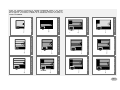
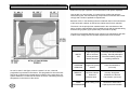
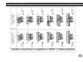
Modelos disponibles. Capacidades y distribución.
N°8:ARO SUPERIOR
N°7: CANTONERAS
N°7: CANTONERAS
Con el objeto de satisfacer al máximo las posibles necesidades de nuestros
clientes, nuestra compañía ha desarrollado una variada gama de modelos
stándard. Las diferencias entre cada uno de estos modelos se encuentran
básicamente en la capacidad de usuarios que simultáneamente pueden usar la
sauna o el confort de los mismos, ya que cuanto más amplia sea una sauna
mayor confort dispone el usuario de la misma. El total de modelos distintos es
MUY AMPLIO, más si se considera las 3 lineas de fabricación CLASSIC
PROFESIONAL y SELECTE y la disponibilidad de los mismos en ABETO DEL
BALTICO o en HEMLOCK DEL CANADA. Esta última sin nudos.
En la siguiente tabla se detallan las dimensiones y capacidades de cada uno de
los modelos de sauna disponibles.
N°3: PUERTA
N°2: MODULOS
pg.3
N°4: MARCO
N°1: ARO BASE
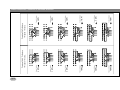
Modelo
Mod.
1-S
Medidas
ext. cm
114X114
S= SENTADO
A= TUMBADO
S=2 A=0
Consumo
Kw/h
3
2-S
130X130
S=2 A=0
3
2-S1
144X130
S=2 A=1
4
3-S
144X144
S=2 A=1
4
3-S1
164X144
S=3 A=1
4
4-S
182X144
S=3 A=1
4
4-S1
194X144
S=3 A=1
5
6-S
210X144
S=4 A=2
5
6-S1
164X164
S=3 A=2
4
6-S2
182X164
S=3 A=2
5
6-S3
194X164
S=4 A=2
5
6-S4
210X164
S=4 A=2
5
5-S
182X182
S=4 A=2
5
5-S1
7-S
194X182
210X182
S=4 A=2
S=4 A=2
5
6
7-S1
194X194
S=4 A=2
6
7-S2
210X194
S=4 A=2
6
8-S
210X210
S=5 A=2
6
8-S1
245X210
S=6 A=3
7
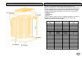
Modelo 6-S1 164x164 cm 4 KW
Modelo 6-S3 194x164 5 KW
Modelo 6-S2 182x164 5 KW
Modelo 3-S 144x144 cm 4 KW
Modelo 4-S 182x144 cm 4 KW
Modelo 6-S4 195x164 cm 5 KW
Modelo 2-S1 130x130 cm 4 KW
Modelo 3-S1 164x144 cm 4 KW
Modelo 6-S 210x144 cm 5 KW
Modelo 4-S1 194x144 cm 5 KW
Modelo 2-S 195 x144 cm 3 KW
Modelo 1-S 114x114 cm 3 KW
Todos los modelos incorporan la fachada EXTERIOR VISTA Y de forma
opcional pueden incorporar cualquier lateral. La altura exterior es de 206 cm.
En la figura 2 se muestra el detalle de la distribución interior de todos los
modelos STANDAR.
pg.4
pg.5
Modelo 7-S 210x182 cm 6 KW
Modelo 7-S1 194x194 6 KW
Modelo 7-S2 210x194 6 KW
Modelo 8-S 210x210 cm 6 KW
Modelo 5-S1 194x182 cm 5 KW
Modelo 5-S 182x182 cm 5 KW
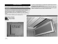
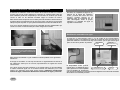
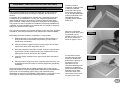
Ejemplo del plano que se adjuntara al manual, para realizar
el montaje de la cabina
CONDICIONES Y PRECAUCIONES PREVIAS A LA INSTALACION
Lineas de conexión para la sauna
Aunque sean pocas aquellas cuestiones a considerar antes de instalar una
sauna, creemos conveniente subrayar algunas que pueden ser interesantes
para facilitar el montaje y que pueden mejorar la funcionalidad y
las prestaciones de la misma.
El elemento de mayor importancia de la sauna es el equipo eléctrico,
destacando, en éste, el “calefactor”, ya que en él se produce el consumo de
electricidad a través de las resistencias.
Condiciones del entorno a la sauna.
A su vez es aconsejable que dicha línea sea independiente y esté protegida con
su magnetotérmico de intensidad adecuada.Normalmente el origen de la línea
deberá encontrarse en el cuadro general de la vivienda.
Las condiciones para realizar el montaje de la cabina de forma correcta son
principalmente dos:
- El elemento sobre el que se soporta la sauna es el aro inferior que encierra
todos los módulos en su parte más baja. Este aro queda directamente sentado
al suelo, por ello éste debe estar perfectamente nivelado. Si el suelo no está a
nivel dificultará el anclaje de los módulos con el aro superior.
Para evitar cualquier tipo de incidente debido al sobrecalentamiento de la
instalación eléctrica del local o vivienda, es imprescindible que la línea a la que
se conecta la sauna esté adecuada a la intensidad y consumo del calefactor.
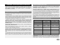
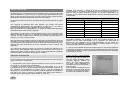
En el siguiente cuadro se detalla la relación adecuada entre el consumo del
equipo eléctrico, la intensidad correcta del magnetotérmico de protección y la
sección del cable de la línea.Se diferencia para cada modelo y según la tensión
del local.
Cuadro de poténcias y acometidas eléctricas.
- Cuando se utiliza la sauna el cuerpo suda, y parte de este sudor acaba
deslizándose hasta el suelo. Por ello el pavimento donde se asienta la sauna
debe ser lo menos poroso y absorbente posible. Si el suelo es absorbente, el
sudor penetrará en el mismo y se irá acumulando en él, junto a las toxinas y
suciedad que arrastra, de forma que facilitará la proliferación de gérmenes,
bacterias y hongos.
CONSUMO EQUIPO
3 KW
15 AMP
.............
2,5 mm
TIPO DE SUELO INDICADO: Pavimento de gres, terrazo o mármol preferiblemente
piezas grandes, 40x40 o 50x50 cm.
4 KW
20 AMP
10 AMP
4 mm
1.5 mm
5 KW
25 AMP
10 AMP
6 mm
1.5 mm
SUELO CONTRAINDICADO: Moqueta, corcho, parquet, cemento o cualquier
material que tenga capacidad de absorción.
6 KW
30 AMP
10 AMP
10 mm
2.5 mm
7 KW
40 AMP
15 AMP
10 mm
2.5 mm
8 KW
40 AMP
15 AMP
16 mm
2.5 mm
9 KW
..............
15 AMP
..............
2.5 mm
10 KW
..............
20 AMP
...............
4 mm
12 KW
..............
20 AMP
................
4 mm
25 AMP
................
6 mm
Cualquier modelo de sauna INBECA incorpora revestimiento machiembrado en
fachada y PUEDE LLEVAR los dos laterales, con lo que se facilita su ubicación.
Debe tenerse en cuenta que la pared trasera NORMALMENTE no incorpora
dicho revestimiento, por lo que, normalmente,deberá quedar contra la pared de
obra.
- Es aconsejable que la sauna esté situada cerca de una ducha para facilitar el
beneficio de la sesión. Aunque esta condición mejora al usuario la toma de
sauna, el agua de la ducha jamás debe alcanzar las paredes de la sauna.
15 KW
INTENSIDAD
MAGNETOTERMICO
220V
380V
..............
SECCION CABLEADO
220V
380V
...........
IMPORTANTE: Las líneas a las que se conecta la sauna deben disponer
siempre de toma de tierra. Si ésta no se conecta puede dar lugar a accidentes de
origen eléctrico. Todo local o vivienda debe disponer de su diferencial general.
pg.6
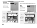
PROCESO DE MONTAJE E INSTALACION
Montaje de la cabina.
La sauna ha sido diseñada y construída especialmente para facilitar el montaje
de la misma a toda persona cuyos conocimientos en carpintería y electricidad
sean mínimos.
Se suministra en un “Kit” completo que incluye todas las piezas y accesorios
necesarios para la instalación. En cada unidad se adjuntan instrucciones
completas que resuelven cualquier duda o cuestión que pueda aparecer. Cada
una de las piezas están marcadas y estas marcas se corresponden a cada fase
del montaje que se encuentra perfectamente ilustrada y explicada, con lo cual
realizar la instalación completa es una tarea agradable y de extrema
facilidad para cualquier profano de la materia.
Las únicas herramientas necesarias para realizar el montaje completo de la
sauna son: Un destornillador con cabeza de estrella, uno con cabeza plana, alicates de corte y una escalera doméstica.
El montaje de la cabina supone completar 5 fases claves:
1- Asentar y atornillar con sus herrajes el aro base completo y a nivel en el lugar
y en el sentido que se deberá tener la sauna una vez completada.
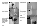
Equipamiento interior. Montaje accesorios
Una vez desembalado el
paquete, procederemos a
seleccionar las diferentes
piezas que forman el aro inferior
( véase figura número 1, 2, 3).
Las situaremos tal y como
indica el texto marcado en las
mismas “FACHADA, DERECHA,
TRASERA e IZQUIERDA.
Figura número 1.
Anclaremos dichas piezas,
entre sí,con las escuadras de
hierro prefijadas en cada una y
los tornillos de medidas 30 mm
tal y como se observa en la
figura número 1 y 2.
2- Encajar los módulos, junto sus cantoneras, sobre el aro base en el orden y
sentido que se ilustra.
3- Una vez cerrado el perímetro de las paredes, encajar las 4 piezas del aro
superior sobre los módulos tal como están marcados. Tornillar las piezas del aro
entre sí y los módulos.
4- Encajar los módulos de techo sobre el aro superior y tornillar los mismos
contra éste aro.
5- Colocar el equipamiento interior, bancos, cabezal, valla de protección, etc. tal
como se detalla y el conexionado del equipo eléctrico (se desarrolla
específicamente).
Todos los herrajes de anclaje que se suministran deben ser utilizados en su
lugar y posición correctas para asegurar el adecuado asentamiento y la
estanqueidad de la cabina. En las siguientes páginas se detalla e ilustra, paso a
paso, el orden de montaje e instalación de forma que, si no se omite
ninguno de ellos, se garantizará el perfecto funcionamiento de la sauna.
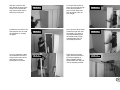
Figura número 2.
Deberá tenerse encuenta que
tal como se situe el aro inferior
determinará la posición de la
sauna una vez montada.
No prosiga el montaje si la
posición no es definitiva.
En caso de montar la cabina
entre paredes de obra, centrar
el rebaje del aro inferior de
fachada al hueco que tenga
para la puerta.
Figura número 3.
pg.7
Seleccionamos los módulos
número 1 y 2 anclándolos
sobre la esquina posterior
izquierda o los números que
mejor convengan de manera
que el último módulo a colocar
sea el de fachada para más
comodidad.
Detalle de las dos piezas de
unión entre módulos para
evitar fugas de calor.
Figura número 4.
Los uniremos con un tornillo de
80 mm tal como indica la figura
adjunta (véase en la figura
número 5).
En las caras vistas de la sauna
fijar las esquinas con los tornillos zincados para taparlos
posteriormente con tapón de
plástico.
Figura número 5.
Los módulos que se vayan
encajando sobre el aro deberán quedar en posición tal que
el texto marcado en ellos
quede visto desde el interior de
la sauna. Una vez realizado lo
anterior, se irán encajando los
diferentes módulos de forma
correlativa según los números
que en ellos encontraremos
hasta cerrar la cabina en sus
cuatro paredes.
Figura número 7.
Los módulos se encajarán
entre sí sin hacer uso de
ningún tornillo ni anclaje.
Únicamente se usarán los
tornillos para anclar las
esquinas a los paneles
adosados correlativamente
(véase en la figura número 5).
Será el aro superior la pieza
clave que unirá toda la
cabina-sauna proporcionándole
su estanqueidad y solidez
propias.
Figura número 8.
Fijar siempre los módulos con
el número que llevan marcado
hacia arriba. De lo contrario no
coincidirán posteriormente los
anclajes de las piezas interiores.
Figura número 6.
Figura número 9.
pg 8
Para colocar el último módulo,
levantarlo la distancia suficiente
para poder encajar la pieza por
los dos lados y dejarla caer por
su propio peso.
Fijar los tornillos de manera
que la cabeza de los mismos
quede enrasada con la madera para el alojamiento del
tapón. Nunca introducirlo más
de lo debido.
Figura número 13.
Figura número 10.
Colocar el conjunto marcopuerta con extremo cuidado
para evitar la posible rotura del
cristal.
Una vez tengamos todas las
paredes
colocadas
abrir
totalmentela puerta y para
evitar que la fachada ceda con
el peso de ésta hasta que esté
fijado por completo el aro
superior.
Figura número 14.
Figura número 11.
Muy importante fijar los tornillos
que hay a la altura del centro del
marco de la puerta para evitar
posteriores movimientos del
mismo.
Colocaremos las piezas que forman el aro superior tal y como
indica el texto marcado en las
mismas: FACHADA,
DERECHA, TRASERA e IZQUIERDA
con las escuadras de hierro
prefijadas.
Figura número 12.
pg.9
Figura número 15.
Fijar todos los módulos de
techo hacia el aro superior con
tornillos de 60 mm.
Fijar el aro superior a los módulos de pared con tornillos de 80
mm.
Fijar un tornillo para cada
módulo y tres para el marco de
la puerta.
Figura número 16.
Figura número 19.
Pasaremos la línea de la sonda
a través del orificio reservado
para ello y conectaremos en el
cuadro de maniobra.
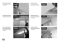
Colocar los módulos de techo
tal y como están marcados en
el aro y en el módulo.
Figura número17.
Para colocar el último módulo
de techo, como indica la foto,
dejarlo caer y ajustarlo desde el
exterior de la sauna.
Figura número 20.
Pasaremos la línea de la luz
interior a través del orificio
reservado para ello y conectaremos en el cuadro de maniobra.
Figura número 18.
Figura número 21.
pg.10
Los cierre de bola del marco, se
regulan hacia dentro o hacia
fuera según convenga para el
ajuste de la puerta de cristal.
Fijar el reposa espaldas encima
de las literas superiores en los
agujeros expresos para ello.
Figura número 22.
Figura número 26.
Deben fijarse todos los tornillos
debajo de los bancos para
evitar movimientos posteriores
provocados por el calor.
Figura número 23.
Fijar los tornillos del soporte de
banco a la litera para reforzar
el conjunto de la cabina de
sauna y evitar dilataciones en
las paredes.
Figura número 24.
pg.11
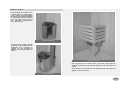
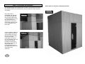
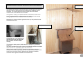
Detalle Acabados Interiores Opcionales.
Prolongaciones de fachada a techo.
La altura estandart de la cabina de sauna es 2.06 m. Para decorar una
habitación de 2.50 m podemos prolongar dicha sauna hasta el techo siguiendo la
misma estructura y diseño.
Sauna con prolongación a techo totalmente terminada.
Una vez montada la cabina
procederemos al montaje
colocando las dos piezas
que forman el ángulo tal como
apreciamos en la figura número
27. Dichas piezas se fijan al
techo de la sauna con un tornillo de 60 mm en el
travesaño de la parte inferior.
Figura número 27.
Es posible también previo pedido
colocar una puerta de acceso
para aprovechar la zona que
queda entre los dos techos.
En las prolongaciones a techo
colocaremos primero las molduras
verticales de suelo a techo.
Una vez fijadas colocaremos
las horizontales tanto en el aro
superior como en la parte
superior de la prolongación.
Figura número 28.
Figura número 29.
pg.12
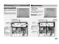
Conexión de la mámpara.
Conexionado eléctrico
Una vez montada la cabina y equipada con sus accesorios, se procederá a realizar
las conexiones eléctricas entre los cuatro elementos clave: Termostato, lámpara,
calefactor y cuadro de mandos.
Del módulo que incorpora todo
el cableado aparecen dos líneas
en paralelo ROJO BLANCO que
pasándolos previamente por el
orificio del aro superior deben
volver a introducirse desde el
exterior del techo por otro orificio
menor que aparece en el techo
indicado “TERMOSTATO”.
Introduciremos el cable manguera
por el orificio del techo, tal como
se observa en la figura.
Fijaremos el portalamparas en la
posición marcada. Destapar el
casco de cristal y conectarlo
según el esquema. A continuación
anclaremos las alcayatas en sus
marcas y colgaremos el protector
de madera de la lámpara.
Una vez padasos los cuatro
cables, conectar a las regletas
de la sonda tal como indica la
figura con cada color.
Posteriormente colocaremos el
protector de la sonda de madera
y lo fijaremos con tornillos de
30 mm con cabeza redonda.
Linea CLASSIC y saunas
con mandos incorporados
al calefactor.
Figura número 31.
Sonda del Termostato. Figura número 30.
Linea PROFESIONAL y
SELECTE:
IMPORTANTE
La instalación eléctrica queda canalizada íntegramente a través del módulo que
incorpora el cuadro de mandos de la sauna. Por la parte superior de este módulo
aparecen:
1234-
Cable
Cable
Cable
Cable
manguera: 5 hilos conexión a red.
manguera: 2 hilos conexión lámpara.
paralelo: 2 hilos 1, 5 mm Rojo-Blanco (Sonda Term. Seguridad)
paralelo: 2 hilos 1, 5 mm Rojo-Blanco (Sonda Term. Seguridad)
Por la parte inferior aparece también el 1- al calefactor.
Todos estos cables deben pasarse por el agujero del aro superior de fachada antes
de fijar el mismo y, posteriormente, los cables de la lámpara(2-) y los de la sonda de
temperatura (3- y 4-) deben pasarse por sus agujeros correspondientes del techo.
En este caso el proceso a seguir
es el mismo que el anterior,pero
se suministran dos apliques.
Uno de ellos corresponde a la
luz roja y el otro a la blanca con
regulador de intensidad.
Aunque normalmente la conexión
vendrá ya realizada, ésta deberá
quedar conectada según la figura
adjunta. Fijaremos los apliques
o portalamparas en la posición
marcada.
En cualquiera de los dos casos,
las lamparas se suministran con
los cables preinstalados.
Figura número 32.
pg.13
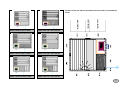
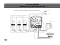
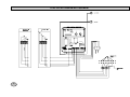
EQUIPOS ELECTRICOS
Esquema eléctrico general opciones de conexión.
ESQUEMA ELECTRICO GENERAL OPCIONES DE CONEXION
LUZ BLANCA
LUZ ROJA
CUADRO SAUNATHERM U
CONEXION
220 TRIFASICO
CONEXION
220 MONOFASICO
CONEXION
380 III
FASE
FASE
FASE
FASE
Luz
Puesta en Marcha
FASE
FASE
NEUTRO
NEUTRO
1x
FASE
TIERRA
Programador horas
Temperatura
Luz blanca
NEUTRO
TIERRA
TERMOSTATO INTERIOR
TIERRA
1 3 5 7
L1 L2 L3 N N K1 K2 U V W
2 4 6 8
1
2
3
4
TERMOFUSIBLE
SEGURIDAD
PTC
CONEXION CALEFACTOR
pg.14
pg.15
9 KW
Potencia Calefactor
8 KW
Potencia Calefactor
7 KW
Potencia Calefactor
6 KW
Potencia Calefactor
5 KW
Potencia Calefactor
4 KW
Potencia Calefactor
Tension 380 V Trifasico
+ Neutro + Tierra.
Tensión 220 Trifásico
+ Neutro + Tierra
9 KW
Potencia Calefactor
8 KW
Potencia Calefactor
7 KW
Potencia Calefactor
6 KW
Potencia Calefactor
5 KW
Potencia Calefactor
4 KW
Potencia Calefactor
Detalle conexiones a calefactor a diferentes tensiones.
tierra
tierra
tierra
tierra
tierra
tierra
neutro
neutro
neutro
neutro
neutro
neutro
fase
fase
fase
fase
fase
fase
fase
fase
fase
fase
fase
fase
fase
fase
fase
fase
fase
fase
tierra
tierra
tierra
tierra
tierra
tierra
neutro
neutro
neutro
neutro
neutro
neutro
fase
fase
fase
fase
fase
fase
fase
fase
fase
fase
fase
fase
fase
fase
fase
fase
fase
fase
Detalle conexiones a calefactor a 380III y 220monofásico
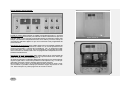
CUADRO DE MANDOS SAUNATHERM, SAUNATHERM U
Y MICROTHERM
Cuadro Modelo: SAUNATHERM:
Este cuadro de mandos dispone,
además de los dispositivos que se
detallan en la figura número de un
termostático automático de seguridad
que corta el suministro eléctrico a los
130°C.
Cuadro Modelo: SAUNATHERM U: Este cuadro es para la linea profesional y selecte
y además de disponer de los dispositivos del modelo Saunatherm, dispone de un
sistema programador de hasta 12 horas antes de su puesta en marcha.
Dispone de tres sistemas de
funcionamiento:
- durante 6 Horas.
- durante 12 Horas.
- uso continuo
Elegir el sistema deseado a través
del puente programado que detallamos
en la figura número 34.
Dispone asi mismo de un dispositivo
de seguridad por tiempo que corta a
las 6 horas de funcionamiento contínuo.
ATENCION: Para realizar esta
operación desconecte la sauna.
Figura número 33.
Figura número 34.
Luz Verde Activado
Luz Roja Calentando
Luz Verde Activado
Luz Roja calentando
Regulador
Temperatura
Interruptor
luz interior
Interruptor
luz interior
Regulador
Temperatura
Interruptor
programador de
puesta en marcha al
activar la sauna
funcionará 6 horas.
Para continuar la
sesión repetir el
proceso.
ATENCIÓN: Para
anular el programador consultar el
manual del puente
programador.
Interruptor
programador
de
puesta en marcha al
activar la sauna funcionará 6 horas . Para
continuar la sesión
repetir el proceso.
Indicador de horas
programadas.
Preprogramador
de tiempo 12 horas
pg.16
Cuadro Modelo: MICROTHERM :
1
7
2
3
8
9
4
5 6
10 11 12
Puesta en marcha: Esta operación se realiza a través del Interruptor n°7. Al pulsar
ponemos en marcha la función para calentar la cabina observaremos que en el
indicador digital n°2 nos marca 80° programados durante 10 segundos. Pasado este
tiempo nos indicará la temperatura interior de la cabina y al mismo tiempo se
encenderá el indicador digital n°3 que nos muestra las horas programadas de
funcionamiento.
Regulación de temperatura: Este cuadro dispone de un termostáto regulable de
40 a 120°C. Para regularlo pulsaremos el botón n°5, en cuanto aparezca la temperatura programada y a través de los pulsadores n°6 y 12 subiremos o bajaremos esta según nos convenga. Una vez regulada en 10 segundos los indicadores volverán a su estado inicial. Una vez programada la temperatura se mantendrá automáticamente.
Regulación de horas programadas: Este cuadro dispone de un temporizador de
horas de funcionamiento, regulable de 30 min m{inimo hasta 6 horas. Esta regulación se realiza a través del interruptor n°11.
Al pulsar el interruptor el indicador digital indica el tiempo al que está programado para regular más o menos tiempo utilizar los interruptores n°6 y n°12. El programador memoriza el tiempo indicado para próximas sesiones.
El interruptor número 10 es un programador horario de hasta 24 horas. Al pulsar nos indica en pantalla el tiempo que tardará el equipo enponerse en marcha. Este interruptor se puede programar de 0 hasta 24 horas.
pg17
Figura número 35.
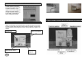
Valla de Protección lineas PROFESIONALES, SELECTE y CLASSIC.
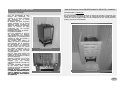
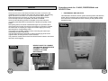
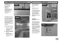
Calefactor S-33, W-25, SCA-45D
PROFESIONAL Y SELECTE:
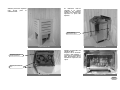
Instalación Calefactor.
Una vez desalojada la tapa
trasera del calefactor, se
conecta a la línea instalada
que aparece en la parte
inferior del módulo.
El detalle de esta conexión
queda reflejado en la figura
siguiente. Para modelos de
sauna con Mandos en Fachada.
Volver a colocar la tapa
protectora con los tornillos
correspondientes.
Realizado este paso, el calefactor quedará instalado.
Una vez superado el proceso
de producción en fábrica,
cada cabina-sauna es montada
íntegramente y conectada para
superar la fase de prueba y
el control de calidad.
Asi, pasado éste último, la
sauna se vuelve a desmontar
para embalar. En el momento
d'e desconectar el calefactor
no se aflojan los bornes de
conexión sino que se cortan
los cables, quedando asi un
segmento de cable colgando
de cada borne con su color
correspondiente.
Esto se hace para evitar una
posible confusión al conectar el
calefactor al montador la sauna
de forma definitiva.
Deberán aflojarse los bornes
para cambiar las puntas que
cuelgan
por
los
cables
originales haciendo coincidir los
colores.
La malla metálica protectora
de las lineas debe quedar
roscada al terminal del calefactor
para evitar tirones.
JAMAS OLVIDE CONECTAR
LA TOMA DE TIERRA INDICADA
CON EL SIMBOLO, PARA EVITAR POSIBLES DESCARGAS
DE TENSIÓN.
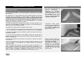
En esta ilustración podemos observar el sistema de anclaje y la posición que
deben tomar tanto el calefactor como la valla protectora para evitar posibles
contactos. Una vez fijada la valla con los tornillos de 70 rnm. colocaremos las
piedras graníticas suministradas.
Figura número 36.
Figura número 37.
Figura número 38.
pg18
Calefactor LANG W25.
CLASSIC:
En línea CLASSIC el sistema
de anclaje y sujeción de la
valla,asi como la posición del
calefactor son esencialmente
los mismos aunque en este
último caso, los tornillos de
fijación de la valla serán de
50 rnm. Como puede observarse
el diseño es también distinto.
ATENCION:
El calefactor debe quedar
siempre centrado en el espacio
que encierra la valla con las
paredes de la sauna para
evitar un sobrecalentamiento
de los elementos que los
componen.
Figura número 40.
Este modelo de calefactor es
indicado para aquellas saunas
cuyo espacio interior no es
muy amplio ya que su dimensión
permite aprovechar en mayor
medida el volumen interior de
la cabina para el usuario de
misma.
Tal como observamos en la figura,
el sistema de fijación de este
calefactor se realiza a través
de los tornillos siministrados que
acoplarán el mismo contra la
pared de la sauna en la esquina
correspondiente.
Para realizar esta operación
deberemos sacar la tapa cromada
previamente y realizar las conexiones con la linea preinstalada
para ello.
pg.19
Figura número 41.
Una vez conenctado el calefactor y fijado sobre la pared colocaremos la
tapa cromada del mismo según se indica en la figura.
Figura número 42.
Por último se procederá a colocar la valla de protección con los
tornillos correspondientes según se ilustra en la figura.
El calefactor quedará siempre centrado en el espacio que encierra la valla, para evitar sobre calentamientos de los
elementos cercanos al mismo.
Calefactor SCA 45
Este calefactor de reciente incorporación posee un diseño nuevo
y muy acorde a las necesidades
de espacio de la mayoria de saunas
de uso particular. Este calefactor
tiene una potencia de 4,5 kw y
sus medidas prácticamente
como las de W-25.
Figura número 43
Su sistema de anclaje consiste
en fijar en la pared la plancha de
Inoxidable que protegerá la
madera una vez colocado el
calefactor y sireve de soporte del
mismo.
Figura número 43.
Dicho soporte tiene 2 orificios arriba y dos más a bajo donde va
encajado el calefactor y porteriormente fijado con dos tornillos en el
centro.
Este calefactor no debe llenarse de piedras hasta arriba parra no
apagar en exceso el calor.
Figura número 44
pg.20
EQUIPOS OPCIONALES.
Hay la posiblilidad de añadir a la sauna equipos opcionales como pueden ser:
Cromoterápia, Cromoterápia de fibra óptica cielo estrellado y musicoterápia.
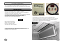
Cromoterápia.
El cuadro de maniobra dispone en la parte inferior izquierda de dos selectores
con los cuatro colores anteriormente inclinados que permiten seleccionar uno o
combinaciones de dos colores a la vez.
La Irradiación de los colores de la cromoterápia se proyectan a través de 4
tubos fluorescentes situados en una bandeja encima del techo de la sauna. Esta
bandeja esta protegina por una ventana completamente estanca que permite
acceder a ella desde el interior de la sauna en caso de avería.
Los colores son una importante fuente de salud para nuestro organismo.
Éste reacciona de forma distinta a las diferentes percepciones coloras o a las
distitas combinaciones antre los colores básicos de la naturaleza.
Este equipo pretende aplicar la CROMOTERÁRIA como complemento en
tratamientos dedicados al bienestar, la relajación y el estado nervioso en
general.
Junto con la sauna entregamos una llave para la apertura de dicha ventana.
Los colores básicos utilizados para este tratamiento son:
Figura número 46.
ROJO: creativo y estimulante.
VERDE: tranquilo y calmante.
AZUL: frio, sereno y sosegado.
AMARILLO: acogedor, cálido y
maduro.
Figura número 45.
pg.21
Cromoterápia de Fibra Óptica Cielo Estrellado
Musicoterápia.
La fibra óptica ocupa un puesto privilegiado en el estudio de la iluminación aplicado al interiorismo y arquitectura.
En la fotografía número49 se aprecia uno
de los equipos audios de alta fidelidad
que puede equipar la sauna.
A través de la fibra óptica conseguiremos
llevar luz donde antes era inviable sin
ningún riesgo.
Equipo para 3 CD,s y sonido esterio.
El equipo incluye la preinstalación de dos
altavoces interiores bajo los bancos
pudiendo conectarlos al equipo o a un
equipo de hilo musical de la propiedad.
Figura número 45.
La fibra óptica se compone tal y como
apreciamos en la figura número 48 de
hilos de monofibra envueltos en una
funda de teflón y filtro ultravioleta.
Un equipo emisor de luz transmite esta a
través de la fibra hasta donde queramos
sin ninguna transmisión de color ni
electricidad.
Características especiales:
Figura número 49.
1- permite el cambio de colores continuo
con un solo emisor de luz.
2- Mínimo consumo.
3- Anulación de rayos UV e infrarrojos.
4- Ideal para áreas con peligro de riego o
interferéncias eléctricas.
Características Técnicas del equipo:
Figura número 45.
Como se puede observar en la figura
número 50 estos altavoces están
especialmente diseñados para aumentar
gracias a su soporte en madera, la caja
de resonáncia y así conseguir un buen
nivel de audio a pesar de estar situado
debajo de las literas de la sauna.
Colocaremos los dos altavoces en los
dos puntos más alejados de la sauna
para lograr la mejor calidad de sonido.
Figura número 50.
pg.22
Equipo especial Bio.
El equipo BIO es un complemento opcional exclusivo que convierte la cabina de
sauna finlandesa en una en la que es posible elegir alternativamente entre
tomar el bano de sauna (Calor seco) o tomar el baño de vapor (Calor húmedo).
Obteniendo combinaciones optimas entre calor y humedad.
Pasados unos minutos, y cuando la sauna ha alcanzado la temperatura
correcta 45-50°C. se activa el generador e inicia la producción de vapor. A
partir de este momento funciona el equipo en su plena capacidad y se
mantiene en las condiciones de temperatura correcta y humedad previamente
seleccionada.
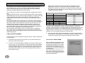
Tabla de Ensayo Equipo Bio en sauna de medidas 144x144x206 cm
El cuadro de mandos se ilustra en las siguientes figuras,desarrollando las reglas
de uso.
TIEMPO min.
TEMPERATURA C
% HUMEDAD RELATIVA
0
25°
60%
Con respecto al calefactor BIO cabe destacar que existen dos partes
perfectamente diferenciadas, los generadores de calor seco y de vapor a
través de un depósito de agua calentado por una resistencia.
Estos generadores son independientes y se ponen en marcha alternativamente
preseleccionando el tipo de baño deseado.
13
47°
45%
18
50°
45%
20
50°
50%
23
50°
55%
El generador de vapor tiene un tiempo limitado de uso ya que el depósito, que
debe ser llenado de agua, se va vaciando al evaporarse el agua por efecto
del calor. Por ello cuando se va a usar hay que verificar que haya agua en el
depósito y en caso contrario llenarlo.
35
45°
73%
47
45°
80%
Este generador de vapor BIO incorpora un dispositivo de seguridad en forma de
contactor en la parte posterior que desconecta la resistencia en caso de que el
nivel de agua este por debajo del mínimo, evitando así una posible averia. Si se
produce este caso, debe llenar de nuevo el depósito y volver a activar este
dispositivo.
Así mismo este elemento incluye una válvula de vaciado del depósito en su
parte inferior. Este dispositivo debe utilizarlo en caso de que vaya a estar un
tiempo prolongado sin usar la sauna, ya que el agua estancada en el depósito
podría dar lugar a la aparición de hongos en el mismo.
Utilización del Equipo Bio
Para el correcto uso de este elemento opcional seguiremos una serie de pasos
que se enumeran a continuación:
1.- Comprobación del nivel de agua del depósito. El nivel correcto será de al
menos 20 cm. por encima de la resistencia.
2.- Puesta en marcha: Colocar el regulador de temperatura a 0 y el de
humedad al nivel que se desee.Activar el interruptor de puesta enmarcha, en
ese momento se encenderán los pilotos verde y rojo del regulador de
temperatura, y unicamente se encenderá el verde del regulador de humedad, lo
que indica que esta en marcha el calefactor dela sauna para calentar el
ambiente pero el generador de vapor todavía no se activa.
pg.23
Una vez alcanzado el nivel correcto de temperatura 45-50 QC, ésta se
mantendrá constante, sin embargo el nivel de humedad depende de la
posición que se haya seleccionado con el regulador. En esta tabla la
posición de este regulador era de aproximadamente 3/4 de vuelta, por
ello el nivel de humedad no supera el 80%, si hubiera estado en 4/4 de
vuelta la humedad hubiera alcanzado el 100%.
3.- Una vez se ha realizado la sesión de baño de vapor con este equipo apagamos
el interruptor de puesta en marcha del cuadro. Observaremos que la sauna continua en funcionamiento un tiempo aproximado de 20 minutos para secar el ambiente producido por el vapor.
Cuadro Modelo: HIDROTHERM:
Este cuadro de maniobra corresponde al equipo Bio de doble función que puede incorporar opcionalmente algunas cabinas de
sauna. Con este equipo generamos calor y vapor obteniendo una
convinación de sauna finlandesa y
baño de vapor.
A este cuadro le corresponde el calefactor Bio en esencia igual al S-33
de apoyo a suelo pero que dispone
asi mismo de generador de vapor.
Figura número 51
Valla de protección especial
más
ancha
para
el
calefactor BIO.
El calefactor BIO va
colgado a la pared
mediante los tornillos
sujetos a la madera que
soportan el peso del
aparato.
Botón Rearme.
Resistencia Vapor.
Figura número 53
Figura número 52.
Detalle conexionado del
calefactor BIO.
Dispone de la conexión
normal a 380 trifásico y
otra linea en monofásico
para alimentación de la
resisténcia especial del
vapor.
Depóstico agua con
bandeja protectora.
Cámara para salida de
aire.
Figura número 54.
Figura número 55.
pg.24
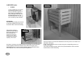
CALEFACTOR OCULTO Y EQUIPOS DE DOSIFICACION.
Dosificación manual de agua.
El sistema de calefactor oculto en el interior de la sauna consiste en conducir
el calor que crea el propio calefactor a través de un conducto para evitar que
dicho calefactor pueda ser manipulado por los usuarios. El conducto por donde
circula el calor es de distintas medidas según el modelo de sauna.
Se coloca un recipiente de agua en un
extremo de la pared del calefactor
oculto y encima del banco del nivel
superior. Cuando tiramos en el
recipiente este es conducido por un
tubo calorífugado hasta el propio
calefactor. La cantidad de agua es
regulada manualmente.
Este sistema está compuesto de una doble pared de similares características a
la própia cabina consiguiendo que el calor fluya entre una pared y la otra hasta
salir por la parte superior en que queda al descubierto la zona de salida de aire.
A su vez el propio calefactor incorpora una bandeja de hierro galbanizado que
conduce el calor a través de ésta para evitar riesgos de incendio.
Dosificación automática de agua.
A través de un temporizador cíclico y con la ayuda de una electroválvula,
inyectamos agua en el calefactor a través de un tubo de cobre que baja por la
pared del calefactor. Al final del tubo hay unos orificios por los que sale el agua
justo encima de la parrilla de piedras.
Cuadro de
temporizador
cíclico
maniobra sauna
ATENCION: Muy importante fijar
dicha bandeja a la pared trasera con
dos tornillos para evitar el movimiento
del calefactor.
Este sistema es utilizado en gran medida en saunas públicas como gimnásios,
hoteles etc.
El riesgo de accidente en este tipo de saunas es significativamente inferior a
las cabinas de sauna que no lo llevan, especialmente en lugares de mucha
concurrencia.
Al no tener acceso al propio calefactor no es posible subir el % de humedad de
la cabina vertiendo agua con el cucharón encima del calefactor por lo cual
existen tres sistemas para lograr dicha función: Instalación dosificación
manual de agua, instalación dosificación automática de agua y esencias.
pg.25
El temporizador cíclico permite
caja estanca con
Llave de
regular tanto la cantidad de agua
electroválvulas de agua.
paso red
que inyectamos en cada impulsión
como la cantidad de impulsiones
que queremos realizar en una sesión de sauna logrando así controlar la humedad
de la cabina con bastante precisión.
Dosificación automática de agua y de esencias.
Aromoterápia múltiple.
Este sistema regula el agua igual que el anterior pero también nos permite a
través de una bomba dosificadora de membrana, inyectar en la red aromas
como eucaliptus, menta, limón etc. Podemos graduar el tiempo de inyección y
la cantidad que interese en cada caso.
cuadro de
maniobra sauna
El sistema de Aromoterápia Múltiple es básicamente lo mismo que la
“Dosificación Automática de agua y esencias”. La única diferéncia existente es
que dispone de 4 depósitos para 4 tipos de aromas diferentes. Con la ayuda del
interruptor selector escogemos el tipo de aroma que queremos para cada
sesión.
depósito
de esencias
4 Tipos distintos de Aromas
Electroválvula de Agua.
Para selección del
tiempo de
dosificación
Para selección del
intervalo de tiempo entre dosificaciones
caja estanca con
electroválvulas de agua.
llave de
paso de red.
Bomba Dosificadora.
Temporizador Cíclico.
temporizador
cíclico.
bomba dosificadora
de membrana.
Llave de paso de Red.
Cuadro de Maniobra.
pg.26
PUESTA EN MARCHA Y FUNCIONAMIENTO.
Normas de uso de la sauna.
Respecto al uso de la sauna es conveniente tener presentes una serie de consejos
para optimizar su funcionamiento y maximizar su duración en condiciones correctas.
Se numeran aquellas de mayor importancia:
Compruebe que todos los elementos de la sauna funcionan y están conectados
correctamente, si no lo estuvieran revise las normas de montaje e instalación.
Una vez instalada la sauna, es conveniente que la cabina no supere los 60°C
durante los 5 primeros días de funcionamiento.
La sauna es un baño de calor seco y no está preparada para producir
vapor con continuidad, por ello no es conveniente vertir más de dos cazos de
agua sobre las piedras del calefactor consecutivamente.
Es recomendable, para prolongar la precisión de los mandos de control, no
variar contínuamente la temperatura programada o conectar y desconectar la
sauna con excesiva frecuencia.
Una vez terminada la sesión de sauna debe desconectarse el interruptor
general del cuadro de mandos.
Jamás deposite ningún objeto sobre las piedras del calefactor aunque no esté
usando la sauna. Ello podría provocar accidentes graves si el objeto es combustible.
Para evitar fisuras o fugas en el cubo para el agua, éste debe contener
normalmente líquido y no debe colocarse a una altura superior a un metro.
Cerrar siempre la puerta una vez terminada la sesión de sauna.
Desconectar el magnetotérmico de protección de la línea de la sauna
cuando no se va a usar en períodos prolongados.
No es conveniente intentar desplazar la sauna de forma compacta, sin
desmontarla previamente, ya que la estructura de la misma podría verse
afectada sensiblemente.
Para evitar averías o efectos no deseados sustituya siempre los componentes con
recambios originales o de las mismas características técnicas.
pg.27
Como debe realizarse la sesión de sauna.
El esquema básico de la sesión de sauna implica una repetición cíclica de etapa
calentamiento y etapa enfriamiento de forma alternada durante al menos 2 o 3 ciclos.
Desarrollo paso a paso:
1.- Ducha de agua caliente.
Ducha higiénica con jabón para limpiar impurezas
del poro. El agua caliente permite iniciar el proceso de abertura del poro de la piel. Es recomendable pasar antes por el WC e incluso en saunas públicas como en las piscinas es obligatorio en cualquiera de los casos.
2.- Secarse correctamente todo el cuerpo.
Si no secamos la piel correctamente retrasaremos
el proceso de transpiración al entrar en la sauna.
3.- Entrada en la sauna (Temperatura 80-90°C).
Inicialmente al entrar en la sauna escojeremos un
banco de nivel inferior pasando posteriormente a
niveles superiores con temperaturas superiores.
En la sauna tomaremos la posición más cómoda
posible intentando que las piernas queden al
mismo nivel o similar. El tiempo de permanencia en
la sauna debe quedar determinado por la necesidad
subjetiva y personal de cada bañista. No es
correcto salir de la sauna hasta que no se siente la
necesidad de refrigerarse, pero tampoco lo es
permanecer en ella aunque se sienta esa
necesidad. En cualquiera de los dos caso, podría
no obtenerse los efectos beneficiosos de la
sauna. Aún así, los periodos de estancia suelen
oscilar entre los 6 y 14 minutos según edad, sexo
y estado nervioso. Hay que tener en cuenta que
una misma persona en momentos distintos puede
sentir la necesidad de salir de la sauna en intervalos
distintos de tiempo, por ello es difícil hablar de
aguante de cada uno en la sauna.
4 - Salida de la sauna. “ Fase de respiración ”.
Antes de salir de la sauna debemos tomar la posición sentado para que el sist.
circulatorio se adapte de nuevo a la posición vertical. Una vez fuera de la sauna
y a temperatura ambiente expiraremos vigorosamente e inspiraremos suavemente.
A ser posible aire fresco para oxigenar con intensidad. Inmediatamente después,
pasaremos a la ducha de agua fria para conseguir una intensa refrigeración de la
piel. Durante esta ducha empezaremos siempre por las extremidades e iremos
acercándonos lentamente a la zona de 1 corazón y la cabeza.
5 - Proceso de repetición ( Iniciar fase 3 ) Hasta 2 ó 3 veces.
Durante la segunda y tercera repetición se suele producir los llamados "GOLPES DE
VAPOR" echando uno o dos cazos de agua sobre las piedras del calefactor para
aumentar la humedad interior. Con ello también aumentará la sensación de calor
dado que la humedad relativa aumentará.
6 - Posible baño de Inmersión.
Contraindicaciones.
Aunque son pocos aquellos casos en los que no es indicado tomar la sauna,
en las siguientes líneas se desarrollan los más importantes. Se incluyen también en esta sección algunas cuestiones importantes aconsiderar antes de
realizar una sesión de sauna.
En primer lugar, como en toda actividad corporal, es aconsejable consultar
con su médico antes de iniciarse en el uso de la sauna, aunque se puede asegurar que más del 95 % de las personas no tienen impedimento alguno para
usarla.
No realizar la sesión de sauna durante la digestión.
No tomar la sauna durante el periodo de gestación.
No tomar la sauna durante la menstruación.
Está contraindicada para aquellas personas con deficiencias cardíacas graves.
Problemas del corazón.
No aconsejable para aquellas personas que sufren problemas de hipotensión.
Casos avanzados de arterioesclerosis y tuberculosis.
7 - Fase de reposo.
Esta fase es seguida por algunos
bañistas y complementa el
efecto de relajación al tomar un descanso en reposo absoluto
durante unos 15 minutos. Se puede
complementar con un baño
de pies con agua caliente.
Posiblemente se seguirá sudando.
8 - Ducha de nuevo para eliminar del todo
el sudor.
9 - Si lo desea, puede ingerir agua o
algún zumo para recuperar el agua
perdida.
En ningún caso tomará bebidas
alcohólicas, durante o inmediatamente
después de tomar la sauna.
Consideraciones específicas.
Si se ha realizado algún ejercicio fatigoso no debe entrar en la sauna sin
haber realizado un previo descanso.
No ingerir bebidas alcohólicas durante el proceso de la toma de sauna.
La sauna no deshidrata. Unicamente reduce el nivel de humedad corporal
de forma temporal, ya que el cuerpo la mantiene de forma regular y vuelve a
absorber agua de la bebida o de la ducha e incluso del aire del ambiente.
No debe salir de la sauna si no siente la necesidad ya que ello impedirá recibir
los efectos de manera correcta. Tampoco debe seguir en la sauna si se siente
la sensación de agobio, ya que puede perjudicar más que favorecer.
Cada persona sentirá la necesidad de salir de la sauna en intervalos
distintos de tiempo. Además la misma persona en momentos distintos
aguantará periodos diferentes según se encuentre su sistema nervioso y
metabólico general. Por ello, no es indicado marcarse un tiempo determinado
de estancia en la sauna y generalizarlo para diferentes personas o momentos.
El baño de sauna es una terapia de relajación y debe producir
bienestar físico y equilibrio mental. Así, la sauna no debe tomarse con
prisas ni omitiendo la mayor parte de los pasos a seguir ya que los
beneficios serán nulos o mínimos.
Para estimular y mejorar los efectos de la sauna, debe tomarse con cierta frecuencia, aunque ésta no debe superar las dos o tres veces por semana.
La forma correcta de tomar la sauna
es completamente desnudo.
pg.28
Uso de los aromas.
Su proveedor habitual puede suministrar "KIT" de MANTENIMIENTO para la
limpieza, desinfección y acondicionamiento de la sauna. Este KIT puede incluir
varios productos de los cuales destaca el aroma de eucaliptus y el desinfectante.
El objeto de estos productos es proporcionar al usuario la posibilidad de extraer
el máximo beneficio del baño de sauna. El uso de estas esencias multiplica los
efectos que la sauna produce sobre el sistema respiratorio además de generar
un ambiente o atmósfera más agradable en el interior de la misma.
Modo de empleo de los aromas.
La esencia se suministra concentrada, por ello jamás se deberá verter directamente
de su envase.
En primer lugar debe diluirse el producto con agua en el cubo que se suministra
con la sauna. La relación aroma-agua determinará la concentración de la mezcla que
cada usuario realizará a su gusto.
Normalmente la proporción deberá estar entre el 5 y el 10% de esencia.
Por el simple hecho de tener en el interior de la sauna el cubo con mezcla de
esencia ya se aprecia el agradable olor de la misma ya que se produce cierta
evaporación, lenta pero contínua.
El mayor efecto de esta esencia se produce cuando se realizan los "Golpes de
vapor" (se vierte mezcla esencia-agua sobre las piedras del calefactor usando
siempre el cazo de madera que se suministra). Este es el momento culminante de los
efectos aromáticos y con él se esparce por
AROMAS.
toda la cabina la agradable sensación de
frescura y facilidad en la respiración.
Los aromas estimulan la oxigenación al
complementar el efecto de dilatación de
las vías respiratorias que ya, de por sí,
produce la sauna.
NO INGERIR.
NO DEJAR AL ALCANCE DE LOS NIÑOS.
MANTENER SIEMPRE CERRADO EL
ENVASE. SE EVAPORA CON FACILIDAD.
Limpieza y desinfección con productos.
Para el MANTENIMIENTO de la sauna también se dispone de los productos para la
LIMPIEZA y DESINFECCION de la sauna.
La función de estos productos es que el usuario de una sauna disponga de la misma
siempre en óptimas condiciones de uso, evitando posibles malos olores,
proliferación de hongos y/o bacterias, lo cual evitará la posiblilidad de contagios de
los mismos.
La importancia del uso de estos productos parece poca, dada la temperatura que
alcanza normalmente una sauna. Ello es cierto a una altura superior a 120-140 cm.
Pero dada la progresividad térmica que se produce en la cabina cuando está a pleno
rendimiento, en las zonas bajas, la temperatura es a veces inferior a 50°C siendo el
nivel de humedad elevado respecto a las zonas altas. Estas condiciones
ambientales a alturas relativamente bajas favorecen esa proliferación que debe ser
combatida con los productos especialmente diseñados para ello.
DESINFECTANTE:
Producto con amplio espectro fungicida y bactericida.
Destruye los gérmenes causantes de los malos olores.
MODO DE EMPLEO: Pulverizaar desde una posición
elevada sobre los bancos y sobre el suelo de la sauna.
FRECUENCIA: Debe aplicarse cada vez que se utiliza.
Desinfectar la sauna después de la limpieza o bien al
final de la jornada una vez se haya cerrado el recinto.
LIMPIADOR:
LIMPIADOR: Producto líquido adecuado para eliminar la
suciedad existente en paredes, suelos y bancos de la
sauna. No transfiere olores a la madera ni al recinto.
Contiene además desinfectante que ejerce una acción
residual potenciadora del producto desinfectante
pulverizador.
MODO DE EMPLEO: Aplicar mediante una esponja empapada o directamente raspando con un cepillo. Se aconseja el uso de guantes en su aplicación.
FRECUENCIA: Saunas públicas, mínimo una vez por
semana. Saunas privadas,mínimo una vez por mes.
NO INGERIR. NO DEJAR AL ALCANCE DE LOS NIÑOS. MANTENER SIEMPRE
CERRADO EL ENVASE.
pg.29
POSIBLES AVERIAS.
Las averías que se pueden producir en la sauna si está correctamente instalada son mínimas o nulas en uso doméstico. Así, se detalla esencialmente aquellas que se puedan producir por no instalar adecuadamente la misma o que con los años de uso se puedan producir. La mayoría de las averías consideradas son poco usuales aunque creemos
oportuno reflejarlas en el siguiente cuadro. Las averías que a largo plazo se puedan producir serán sobre el equipo eléctrico, ya que la cabina si está correctamente montada no las provocará. Si se produciera alguna rotura en algún elemento por accidente se procederá a su sustitución.
PROBLEMA
S I N TO M A S
CAUSA
PROBABLE
VERIFICACIÓN
DE LA CAUSA
SOLUCION
AL PROBLEMA
La sauna no supera 50°C
Contactor seguridad averiado
Termohigrómetro averiado.
Regulador manual nivel incorrecto.
Resistencia fundida.
Sensor interior averiado.
Reles averiados
Inspección
Inspección.
inspección.
Inspección calefactor.
Verificar pieza sensor.
Presionar puerta.
Sustituírlo.
Regular bien.
Sustituir.
Sustituir.
Se dispara diferencial del local.
Conexionado incorrecto.
Exceso de agua sobre el calefactor.
Resistencia comunicada al chasis.
Verificar manual.
Desconectar la sauna.
Verificar de que resistencia se trata.
Conectar correctamente.
Esperar 24 horas. Volver a conectar.
Desmontar y sustituir resitencia.
La sauna no activa.
No hay corriente en la conexión.
Sensor seguridad averiado.
Fusible del cuadro fundido.
Contactor bloqueado desactivado.
Conexionado incorrecto.
Transformador averiado.
Verificar magnetotérmico.
Verificar termofusible.
Inspección cuadro de mandos.
Inspeccionar contactor cuadro mandos.
Verificar manual.
Activarlo.
Sustituirlo.
Sustituir fusible del cuadro.
Consultar su proveedor habitual.
Conectar correctamente.
Subida de temperatura sin control.
Contactor bloqueado activado.
Regulador manual nivel máximo.
Inspeccionar contactor cuadro mandos.
Inspección.
Consultar su proveedor habitual.
Regular correctamente.
La lámpara no funciona.
Bombilla fundida.
Conexionado correctamente.
Verificar.
Verificar manual.
Sustituir.
Conectar correctamente.
Se dispara el magnetotérmico
de protección.
Sobrecalentamiento de la línea de
la sauna.
Cruce en el calentador.
Resistencia cruzada.
Verificar manual.
Corregir error en la línea.
Inspeccionar elemento.
Verificar que resistencia.
Corregir error un especialista.
Sustituir.
pg.30
INDEX
Description
Turning on and operation.
Origin and evolution of the sauna…… ............................................ 1
General Description of the sauna concept...................................... 1
Air Convection and renovation system…….................................... 2
Basic materials and components….. ............................................... 2
Detail of construction and anchorage .............................................. 3
Models available. Capacity and distribution….. ............................. 3
Guidlines for using the sauna............................................................. 35
How to sauna session should be conducted...................................... 35
Contraindications
......................................................................... 36
Use of aromas………..........................................................................37
Conditions and precautions before installation.
Conditions for the area surrounding of the sauna..............................6
Connection lines for the sauna………................................................6
Electrical power and connection tables………. .................................6
Assembly and installation process.
Assembling the booth ..................................................................... 7
Wall to ceiling extensions………….. ...............................................12
Electrical connection… ....................................................................13
Electrical equipment.
General electrical scheme, connection options….......................... 14
Control Panel……. ......................................................................... 16
Heaters…… ................................................................................... 21
Optional equipment.
Chromotherapy............................................................................... 26
Fibre optic starry sky chromotherapy………… ............................... 27
Music Therapy................................................................................. 27
BIO Special equipment…………… ..................................................28
Hidden heater and regulating equipment.
Manual water regulation
......................................................... 32
Automatic water regulation…….. ................................................... 32
Automatic water and essential oil regulation ................................ 32
Multiple aromatherapy.................................................................... 33
Troubleshooting .............................................................................. 38
DESCRIPTION
ORIGINS AND EVOLUTION OF THE SAUNA BATH
The Sauna bath has its secular origins in the Baltic areas. Its initial objective
was to combat the consequences of the low temperatures suffered by the
inhabitants of the area, especially in winter. As time passed and there was
no longer such a strong need to be protected from the local climate due to
technological advances, the sauna was converted into a ritual or type of
family ceremony that was very effective in reaching the state of well-being
and physical and psychological relaxation necessary in any modern society.
Today, in the countries of this area, especially FINLAND and SWEDEN, the
sauna is considered an essential element of all activity whose goal is to
arrive at the state of physical well-being. Likewise, it is considered a
fundamental therapy for mental relaxation.
Given this, in these countries and in others with high levels of social
development, the use of saunas has expanded dramatically, reaching the
point that, in certain areas, a large number of homes are equipped with this
therapeutic element.
As we have seen, the objective of the sauna is relaxation and physical and
mental well-being. Although it has numerous positive effects on the body, its
principal effect is not weight loss, though is always aided if accompanied by
an appropriate low-calorie diet.
Effects of a sauna bath on the body:
GENERAL DESCRIPTION OF THE SAUNA CONCEPT
At the beginning, the saunas was a simple caity made in the surface, into
whiche were placed stones previously heated in the fire to produce the heat.
Later, with technological advancements, people began to build saunas in little
wood huts, always outside. The heat was produced via a tradilional chimmey
within the sauna that, when heating the stones, expelled the smoke through a
direct output.
Nowadays, Finnish saunas have evolved with the technological advances
and have undergone important variations in construction, which are explained
in this manual.
Currently, Finnish saunas are “vertebrate” constructions with modular wooden
structures, insultaing material in the interior and covered in tongued and
grooved paneling. It is equipped with bunks or benches and the interior
accessories may be freatly vaired and sophisticated.
The essential element of a
sauna is the electrical
equipment that generates
the heat, warming the air
to very high temperatures
inside the sauna, while
maintainin a very low level
of humidity due to the
wood’s absorption.
¾
Relaxing the nerves. Relaxation.
¾
Dilation of respiratory branches. Oxygenation.
¾
Peripheral vasodilation.Stimulating blood flow in the extremities.
Elevating the heart rate. Stimulating the circulatory system.
The sauna is built separate from the home or other building where it is
located. At the same time, the majority of saunas are interior, although they
may also be exterior.
¾
Removing toxin from the pores. Sweat glands.
Of course, the sauna generates completely dry heat, reducing the humidity in
the air while heating due to absorption. Because of this, it is erroneous to
accosiate suanas with steam, a phenomena that is unique to “STEAM
BATHS”, whose effect and conception are essentially different.
¾ Improving the elasticity of muscular tissue and joints.
1
AIR CONVECTION AND RENOVATION SYSTEM
BASIC SAUNA MATERIALS AND COMPONENTS
The materials used in the manufacturing process of the sauna largely
determine its proper operation and the funcations and options expected.
Just as with any other porduct, it is valued for its quality and optimum
results during use; the manufacturing components of a Finnish sauna must
comply with a series of qualitative requirements.
Because of this, in the following lines the materials used in the manufacture
of the sauna are oultined, as well as the criterias used in their selection.
The wood: It is the principal raw material used in the manufacture of the
sauna, and the characteristics of this material, along with the manufacturing
and anchoring system, figure prominently in the sauna’s quality.
The sauna incorporates different types of wood in its manufacture and each
of them must comply with the concrete requirements for its functions.
TYPE OF
WOOD
BALTIC
FIR
As can be seen in this figuer, when the sauna is in use, a thermal
progression is produced in the interior. This progression is due to the fact
that the air is lighter as the temperature increases. At the same time, the
system allows for a continuous renovation of the air, maintaining the high
temperature in the interior of the sauna.
2
PIECE(S)
ESSENTIAL
CHARACTERISTIC(S)
Tongue and grooved Thermal contrast resistance
Bench structure
Porosity. Humidity absorption.
Frame perimeter
Thermal insulating capacity.
Module structure
Cracking resistance.
CANADIAN
HEMLOCK
Tongued an grooved
exterior
ABBACHI SAMBA
Benches / Bunks
Head rest
Protective fence
FIBRE
Rear-Ceiling cover
PRESSBOARDS
Same characteristics
(no knots)
Porosity. Songiness.
Resistance to thermal
Transmission (no knots)
Resistance and duration
Capacity thermal insulation
DETAIL OF COMPONENT POSITION
MODELS AVAILABLE. CAPACIETIES AND DISTRIBUTION
With the aim to completely satisfy the posible needs of our clients, our
company has developed a varied range of standard models. The
differences between each of these models are basically in the capacity –the
number of people that may simultaneously use the sauna-and their comfort,
since the larger the sauna is, the more comfortable for the user. The range
of different models is VERY DIVERSE, even more so if you consider the 3
manufacturing lines of :
- CLASSIC
- PROFESIONAL
- SELECTE
and their avilability in BALTIC FIR or in CANADIAN HEMLOCK. The latter is
without knots. The dimensions and capacities of each of the models
available are detailed in the following table
Model
Mod.
1-S
2-S
2-S1
3-S
3-S1
4-S
4-S1
6-S
6-S1
6-S2
6-S3
6-S4
5-S
5-S1
7-S
7-S1
7-S2
8-S
8-S1
External
S= SEATED
dimensions. cm A= RECLINED
114X114
S=2 A=0
130X130
S=2 A=0
144X130
S=2 A=1
144X144
S=2 A=1
164X144
S=3 A=1
182X144
S=3 A=1
194X144
S=3 A=1
210X144
S=4 A=2
164X164
S=3 A=2
182X164
S=3 A=2
194X164
S=4 A=2
210X164
S=4 A=2
182X182
S=4 A=2
194X182
S=4 A=2
210X182
S=4 A=2
194X194
S=4 A=2
210X194
S=4 A=2
210X210
S=5 A=2
245X210
S=6 A=3
Consumption
Kw/h
3
3
4
4
4
4
5
5
4
5
5
5
5
5
6
6
6
6
7
3
All models have the EXTERIOR VIEW front and may also incorporate any side optionally. The exterior height is 206 cm. Figure 2 shows the detail of
the distribution of all the standards models.
Model 1-S 114 x 114 cm 3 Kw
Model 2-S 195 x 114 cm 3 Kw
Model 4-S1 194 x 144 cm 5 Kw
Model 6-S 210 x 144 cm 5 Kw
Model 2-S1 130 x 130 cm 4 Kw
Model 3-S 144 x 144 cm 4 Kw
Model 6-S1 164 x 164 cm 4 Kw
Model 6-S2 182 x 164 cm 5 Kw
Model 3-S1 164 x 144 cm 4 Kw
Model 4-S 182 x 144 cm 4 Kw
Model 6-S3 194 x 164 cm 5 Kw
Model 6-S4 194 x 164 cm 5 Kw
4
Example of the plan that will be attached to the manual, to assemble the
booth.
Model 5-S 182 x 182 cm 5 Kw
Model 5-S1 194 x 182 cm 5 Kw
Model 7-S 210 x 182 cm 6 Kw
Model 7-S1 194 x 194 cm 6 Kw
Model 7-S2 210 x 194 cm 6 Kw
Model 7-S2 210 x 194 cm 6 Kw
5
CONDITIONS AND PRECAUTIONS BEFORE
INSTALLING
Although there are only a few things to keep in mind before installing a
sauna, we would like to point out some of them that may be of interest, to
failitate assembly and that may improve operation and the options of the
sauna.
CONDITIONS FOR THE AREA SURROUNDING THE SAUNA
There are two main conditions for assembling the booth correctly:
-
-
The element upon which the sauna is supported is the lower frame,
which encloses all the modules in its lowest part. This frame is set
directly on the ground, which requires that the earth below it be
perfectly leveled. If the earth is not level, it will be difficult to anchor
the modules with the upper frame.
When you use the sauna, your body perspires, and part of its
perspiration eventually makes its way to the floor. Due to this, the
pavement where the sauna is situated should be the least porous
and absorbent possible. If it is absorbent, the perspiration will
penetrate it and it will accumulate there, along with the toxins and
grime that it carries with it, which will facilitate germ, bacteria and
fungus growth.
TYPE OF FLOORING SUGGESTED: Stonewate, terrazo or marble,
preferably large pieces, 40x40 or 50x50 cm.
CONTRAINDICATED FLOORING: Carpeting, cork, parquet, cement or any
other absorbent material.
All INBECA sauna models incorporate a tongued and grooved panel for the
front of the sauna and MAY INCLUDE the two sides as well, which facilities
its positioning. Its important to consider that the rear wall does not
NORMALLY incorporate a lining, so normally, it will have to stay against the
constructed wall.
-
6
It is advisable that the sauna is situated close to a shower to
maximise the benefits of the session. Although this condition
improves the user’s sauna experience, the water must never touch
the walls of the sauna.
CONNECTION LINES FOR THE SAUNA
The most important element of the sauna is the electrical equipment,
particularly the “heater”, in which the electricity is produced through the
electrical resistance.
To avoid any type of incident due to overheating of the premises’ or homes’
electrical installation, it is essential that the line to which the sauna is
connected is appropriate for the intensity and consumption of the heater.
In turn, it is advisable that the line mentioned is indepenent and is protected
with its own circuit breaker, set at the appropriate intensity. Normally the
origin of the line should be found in the general electrical panel of the home.
In the table below, the ocnnection details between the consumption of the
electrical equipment, the correct intensity of the protective circuit breaker and
the section of the line cable will be given. Connections will differ depending
on the model and on the voltage of the premises.
ELECTRICAL POWER AND CONNECTION TABLE
INTENSITY
EQUIPMENT
CIRCUIT BREAKER
SECTION OF WIRING
CONSUMPTION
3 KW
4 KW
5 KW
6 KW
7 KW
8 KW
9 KW
10 KW
12 KW
220V
15 AMP
20 AMP
25 AMP
30 AMP
40 AMP
40 AMP
..............
..............
..............
380V
..............
10 AMP
10 AMP
10 AMP
15 AMP
15 AMP
15 AMP
20 AMP
20 AMP
220V
2,5 mm
4 mm
6 mm
10 mm
10 mm
16 mm
..............
..............
..............
380V
..............
1,5 mm
1,5 mm
2,5 mm
2,5 mm
2,5 mm
2,5 mm
4 mm
4 mm
..............
25 AMP
..............
6 mm
15 KW
IMPORTANT: The lines to which the sauna is connected must always be
grounded. If it is not connected, it can result in electrical accidents. All
premises and homes should have a general differential.
ASSEMBLY AND INSTALLATION PROCESS
ASSEMBLING THE BOOTH
The sauna was designed and constructed especially so that it could be
assembled by people whose knowledge in carpentry and electricity is
minimal.
A complete “Kit” is supplied which includes all the necessary pieces and
accessories for the installation. In every unit, complete instructions are
attached that will resolve any doubts or questions that may arise. Each
piece is marked. These marks correspond to each phase of the assembly.
The process on how to complete the installation is perfectly illustrated and
explained. Thus the installation is a pleasant task and should be extremely
easy for any amateur on the subject.
The only tools necessary for complete assembly of the sauna are: A phillips
screwdriver, a flat-head screwdriver, wire cutters and a household ladder.
Assembling the booth should be completed in a 5 key phases:
1. Settle and screw on the complete base frame with its fittings in a
level position and in the location and position you will have the
sauna when it is finished.
Once the packet is
unpacked, we will proceed
to select the different
prices that make up the
lower frame (see figures
1,2,3). We will situate them
in the wat indicated in the
text marked on them
“FRONT, RIGHT, REAR
AND LEFT”
Secure the mentioned
pieces to each other, using
the prefixed iron set
squares on each one and
the 30 mm screws, as
shown in figures 1 and 2.
FIG Nº 1
FIG Nº 2
2. Insert the modules, together with the corner pieces, into the base
frame in the same order and position shown.
3. Once the perimeter of the walls is closed, insert the 4 pieces of the
upper frame onto the modules as they are marked. Screw in the
frame pieces to each other and to the modules.
4. Insert the ceiling modules into the upper frame and screw them in
against it.
5. Place the interior equipment, seats, hearests, portective fence, etc.,
as detailed and the connection of electrical equipment (specifically
explained).
All the anchorage pieces that are pplied should be used in their correct
place and position to ensure the appropriate settlement and watertightness
of the booth. On the following pages, step by step instructions and
illustrations are given for the installation and assembly ina way that, if none
of the steps ar emised, a perfectly functioning sauna is guaranteed.
It is important to bear i
mind that how the lower
frame was situated will
determine the position of
the sauna once it is
assembled. Do not
continue assembling if the
position is not definitive.
When assembling to booth
between interior walls,
centre the notch of the
lower frame of the front to
the space for the door.
FIG Nº 3
7
Let’s select modules 1 and
2, moving them to the back
left corner, or whichever
numbers work best so that
the last module to put in
place is the front. This will
make completing the
process more comfortable.
We can now join them
together with an 80mm
screw as indicated in
figure 5). On the sides of
the sauna that are visible,
affix the corners with the
zinc screws, which are to
later be covered with
plastic caps.
As you mount the modules
on the lower frame, they
should be in a position that
allows you to still see the text
marked on them from within
the sauna. Once this is
accomplished, the various
modules will fit together in
correlation, according to the
numbers found on them
(until the booth is enclosed in
its four walls).
8
FIG Nº 4
FIG Nº 5
FIG Nº 6
Detail of the joining pieces
between modules to avoid
heat escapes.
The modules will fit
togehter without the need
for any screws or anchors.
Screws will only be used to
anchor the corners to the
correlating adjacent panels
which (see figure 5). The
upper frame will be the key
piece that joins the whole
booth together, giving it its
watertightness and own
strength.
Always affix the modules
so that the number marked
is at the top. Otherwise,
the anchors will not
coincide with the interior
pieces.
FIG Nº 7
FIG Nº 8
FIG Nº 9
Affix the screws so that
their heads are flush to the
wood to accomodate the
cap. Necer screw them in
further than this point.
Position the door-frame set
with extreme care to avoid
the possiblity of cracking
the glass.
It is very important to affix
the screws that are at the
height of the centre of the
door frame to avoid
subsequent movement.
FIG Nº 10
FIG Nº 11
FIG Nº 12
To put the last module in
place, lift it up high enough
to be able to insert the
piece on both sides and
then let it drop under its
own weight.
Once we have all the walls
positioned, open the door
completely, to avoid the
front wall collapsing with
the weight, keep it open
until the upper frame is
completely anchored.
Place the pieces of the
upper frame as indicated
by the text marked on
them: FRONT, RIGHT;
REAR AND LEFT with the
iron set squares prefixed.
FIG Nº 13
FIG Nº 14
FIG Nº 15
9
Affix the upper frame to
the wall modules with 80
mm screws.
FIG Nº 16
Place the roof modules as
they are marked on the
frame and on the module.
FIG Nº 17
To put the last module in
place, as indicated in the
photo, drop it into place
and adjust it from outside
the sauna.
10
FIG Nº 18
Affix all of the roof
modules to the upper
frame with 60 mm screws.
Pass the sensor line
through the hole reserved
for it, then connect it to the
control panel.
Pass the light cable
through the hole reserved
for it, then connect it to the
control panel.
FIG Nº 19
FIG Nº 20
FIG Nº 21
The door frame ball catch
can be adjusted either
towards the inside or the
outside, depending on th
eplacement of the glass
door.
All the screws should be
fixed below the benches to
avoid subsequent
movement caused by the
heat.
Affix the bench support
screws to the bunk to
strengthen the whole
sauna booth and to avoid
expansion of the walls.
FIG Nº 22
Affix the back rest on the
upper bunks in the holes
made for it.
FIG Nº 25
FIG Nº 23
FIG Nº 24
11
WALL TO CEILING EXTENSIONS
Sauna with roof extension completely finished.
The standard height of the sauna booth is 2.06m. For rooms that are 2.50m,
the standard sauna can be extended up to the roof with the same structure
and design.
FIG Nº 28
Once the booth is
assembled, proceed with
the assembly by placing
the two pieces that make
up the angle seen in figure
26. There pieces are
affixed to the roof of the
sauna with a 60mm screw
in the crosspiece of the
lower part.
Its also possible, subject to
order, to place an access
point between the roof of
the sauna and the ceiling
of the room to take
advantage of the space.
For the extensions, we will
first place the vertical
borders from the floor to
the ceiling. Once they are
affixed, place the
horizontal pieces both in
the upper frame and in the
upper part of the
extension.
12
FIG Nº 26
FIG Nº 27
ELECTRICAL CONNECTION
Once the booth is assembled and equipped with accessories, make the
electrical connections between the four keys elements: Thermostat, lamp,
heater and control panel.
From the module that includes all the wiring, two parallel cables RED WHITE
can be seen that pass first through the hole in the upper frame and should be
Re-inserte from the exterior of
the roof through the other,
smaller hole in the roof labeled
THERMOSTAT.
FIG Nº 29
Once the four cables are in
place, connect them to the
sensor terminal strip according
to colour, as indicated in the
figure.
Then, place the wooden
sensor protector in position
and attach it with 30 mm round
head screws.
IMPORTANT:
The electrical installation is channelled completely through the module that
includes the sauna’s control panel. In the upper part of this module, the
following can be seen:
1- Flexible cable: 5 network connection threads.
2- Flexible cable: 2 2 lamp connection threads.
3- Parallel cable: 2 strands 1, 5 mm Red-White(Thermostat sensor, Security)
4- Parallel cable: 2 strands 1, 5 mm Red-White (Thermostat sensor,security)
Lamp connection
CLASIC line and saunas with remote controls for the
heater.
Introduce the flexible cable
through the hole in the
ceiling, as shown in the
figure.
Affix the lamp holders in the
position marked. Uncover
the lamp globe and connect
it as in the diagram. Fasten
the hooks in their marked
positions and hang the
wooden lamp protector.
FIG Nº 30
PROFESIONAL and SELECTE line:
For there, the procedure to follow
is the same as before, but two
wall lamps are supplied. One of
them is the red light and the
other is the white, which has an
intensity regulator.
Although the connection will
usually come already completed,
it must be connected as in the
attached figure. Affix the wall
lamps and holders in the position
marked. For each of therre, the
lamps are supplied with preinstalled cables.
FIG Nº 31
In the lower part the 1- heater is also seen.
All the cables should be passed through the hole in the upper frame of the
front wall before affixing it and, subsequently, the lamp cables (2-) and those
of the temperature sensor (3- and 4-) should be passed through their
corresponding holes in the ceiling.
13
ELECTRICAL EQUIPMENT
GENERAL ELECTRICAL SCHEME, CONNECTION OPTIONS
ESQUEMA ELECTRICO GENERAL OPCIONES DE CONEXION
LUZ BLANCA
LUZ ROJA
CUADRO SAUNATHERM U
CONEXION
220 TRIFASICO
CONEXION
220 MONOFASICO
CONEXION
380 III
FASE
FASE
FASE
FASE
Luz
Puesta en Marcha
FASE
FASE
NEUTRO
NEUTRO
1x
FASE
TIERRA
Programador horas
Temperatura
Luz blanca
NEUTRO
TIERRA
TERMOSTATO INTERIOR
TIERRA
1 3 5 7
L1 L2 L3 N N K1 K2 U
2 4 6 8
V W
1
2
3
4
TERMOFUSIBLE
SEGURIDAD
PTC
CONEXION CALEFACTOR
14
9 KW
Potencia Calefactor
8 KW
Potencia Calefactor
7 KW
Potencia Calefactor
6 KW
Potencia Calefactor
5 KW
Potencia Calefactor
4 KW
Potencia Calefactor
fase
fase
fase
fase
fase
fase
fase
fase
fase
fase
fase
fase
fase
tierra
tierra
tierra
tierra
tierra
tierra
neutro
neutro
neutro
neutro
neutro
neutro
fase
fase
fase
fase
fase
fase
fase
fase
fase
fase
fase
fase
fase
fase
fase
fase
fase
fase
9 KW
fase
Potencia Calefactor
fase
8 KW
fase
Potencia Calefactor
fase
7 KW
neutro
fase
Potencia Calefactor
tierra
neutro
6 KW
tierra
neutro
Potencia Calefactor
tierra
neutro
5 KW
tierra
neutro
Potencia Calefactor
tierra
neutro
4 KW
tierra
Potencia Calefactor
Tension 380 V Trifasico
+ Neutro + Tierra.
Tensión 220 Trifásico
+ Neutro + Tierra
CONNECTION DETAILS FOR HEATING AT DIFFERENT VOLTAGE
Detalle conexiones a calefactor a 380III y 220monofásico
15
CONTROL PANELS
SAUNATHERM:
This control panel, in addition
to the features detailed in the
figure, has an automatic safety
thermostat that cuts off the
electricity supply at 130ºC.
Likewise, it has a time safety
feature that cuts off after 6
hours of continuous operation.
FIG Nº 32
SAUNATHERM U:
This panel is for the Profesional and Selecte Line. As well as having the
features of the Saunatherm model, it has a programming system of up to 12
hours before it is turned on. It has three operational systems:
- 6 hours.
- 12 hours.
- continuous
Choose the desired system
using the programmable
bridge, which is detailed in
figure 34.
ATTENTION: To carry out this
operation, disconnect the
sauna.
16
FIG Nº 33
HEATER
Heater installation
Once the rear cover of the heater has been removed, connect it to the
installed line that is located on the lower part of the module. The following
figuer shows this connection. For sauna models with Wall Controls.
Place the protective cover back on using the corresponding screws.
Once this step has been completedd, the heater is installed.
Once the manufacturing process is complete, every sauna-booth is
completely assembled and connected for the testing and quality control
phase.
After pasing these, the sauna is dismantled again to be packed. When
disconnecting the heater, the terminal connections not loosened, instead
the cables are cut, keeping one segment of cable hanging form every
terminal with its corresponding colour.
This avoids any possible confusion when connecting the heater upon
assembling the sauna definitively.
The terminals should be loosened to change the hanging ends for the
original cables, ensuring that the colours coincide.
The protective metallic mesh of the lines should remain bolted to the heater
terminal to avoid tugging.
FIG Nº 35
Protective guards for CLASIC, PROFESIONAL and
SELECTE lines.
PROFESIONAL AND SELECTE:
This illustration shows the anchor system and the position that both the
heater and the protective fence should be in to avoid possible contact.
Once the fence is fixed with the 70mm screws, put the granite stones
supplied in place.
FIG Nº 37
NEVER FORGET TO CONNECT
THE GROUND, INDICATED WITH
A SYMBOL, TO AVOID
POSSIBLE VOLTAGE
DISCHARGES.
FIG Nº 36
20
18
17
19
21
LANG W25 heater
FIG Nº 38
FIG Nº 40
CLASSIC
In the CLASSIC line, hte anchor
and fastening system of the
fence as well as the position of
the heater are essentially the
same, although in this last case,
the fastening screws for the
fence will be 50 mm. As you can
see, the desing is also different.
ATTENTION:
The heater should always be centred
in the space between the fence and
the sauna walls to avoid overheating.
This model of heater is
suitable for those saunas
where the interior space
isn’t very large. Its
dimensions allows for
efficient use of space,
considering the interior
capacity of the booth.
FIG Nº 39
As shown in the figure, the fixing process for this heater is done using the
screws supplied, which will connect it to the wall of the sauna in the
appropriate corner. To carry out this operation, we must first take off the
chrome-plated cover and connect the pre-installed line.
22
Once the heater is connected and fastened to the wall, put the cover back on as
indicated in the figuer.
Finally, put the protective fence in place using the corresponding screws, as
shown in the figure.
The heater will always remain centre in the space between the fence and the
sauna walls to avoid overheating.
SCA 45 Heater
This recently-introduced
heater has a new design
that meets the space
requirements for the
majority of personal use
saunas. It has a power
of 4.5kw and its
dimensions are almost
the same as the W-25.
FIG Nº 41
FIG Nº 43
FIG Nº 42
Its fastening system
consists of affixing the
stainless steel panel to
the wall, which will
protect the wood once
the heater is put in place
and will also serve as a
support for it.
This support has two holes at the top and two lower down where the heater is
fitted and subsequently affixed with two screws in the centre.
The heater should not be filled to the top with stones, so that it doesn’t switch
off due to excessive heat.
23
OPTIONAL EQUIPMENT
There is a possiblity to add optional equipment to the sauna, sucha
as:chromotherapy, fibre optic starry sky, chromotherapy and music therapy.
CHROMOTHERAPY
Colours are and important source of health for our bodies.
Our bodies react in different ways to different colours or to the different
combinations of the basic colours found in nature.
This equipment applies CHROMOTHERAPY as a compliment to treatments
for one’s well being, relaxation and general state of being.
Along with the sauna, we deliver a key for opening this window.
The basic colours used for this treatment are:
FIG Nº 46
RED: creative and stimulating.
GREEN: calming and soothing.
BLUE: cool, serene and calm.
YELLOW: warm, cosy and cheerful.
FIG Nº 48
The irradiaton of the Chromotherapy colours is projected through 4
florescent tubes situated in the tray above the ceiling of the sauna. This tray
is protected by a completely watertight window, which can be accessed
from the interior of the sauna in case of a breakdown.
FIG Nº 50
Cuadro de mandos:
A
On the lower part of the control panel, there are two sleector with the four
previously mentioned colours, which allow you to select one, or a
combination or two colors at a time:
24
26
FIG Nº 49
B
A: Selector de programación y puesta
en marcha.
- Escala del 0 al 4: horas de
funcionamiento
- Escala del 0 al 8: Programador
horario de puesta en marcha .
Ejemplo: Colocando el selector en el
numero 7 programamos la sauna para
que se ponga en marcha al cabo de 7
horas, el tiempo de funcionamiento será
de 4 horas con posterior parada
automática.
B: Regulador de temperatura de la
cabina.
De menor a mayor en el sentido horario
de las agujas del reloj
25
FIBRE OPTIN STARRY SKW CHROMOTHERAPY
Fibre optics have a
privileged place in the
study of lighting,
applied to interior
design and
architecture.
Using fibre optics we
have been able to put
lights in place where it
was previously
impoosible to do so
whitout risk.
Fibre optics, as we can
see in figure 51, is made
up of monofibre threads
wrapped in a sheath of
teflon with an ultraviolet
filter. A light transmitting
equipment transmits light
through the fibre to
wherever we want, without
transmitting any colour or
electricity.
Special Characteristics:
1. Allows for continuous
changing of colours
with only one light
transmitter.
2. Minimal consumption.
3. Cancels UV and infrared rays.
4. Ideal for areas with a
danger of water
infiltration or electrical
interference.
FIG Nº 51
MUSIC THERAPY
Photo 49 shows hi-fi
audio euqipment that
may come with the
sauna.
FIG Nº 53
Equipment for 3 CDs
and stereo sound.
The euqipment inclued
the pre-installation of two
interior loudspeakers
below the benches,
connecting them to the
equipment or to the
background music of the
property.
FIG Nº 52
Technical
specifications of the
equipment:
As shown in figure, 54,
these loudspeakers are
especially designed to
amplify. Thanks to its
wooden support, the
echo box can achieve a
good audio level despite
being situated below the
benches of the sauna.
Place the two
loudspeakers in the two
points furthest away
from one another within
the sauna to produce the
best quality sound.
FIG Nº 54
27
BIO SPEACIAL EQUIPMENT
BIO equipment is an exclusive and optional accessory that converts the
Finnish sauna booth into one in which is possible to alternate between
taking a sauna (dry heat) or taking a steam bath (wet heat). Obtaining
optimal combinations between heat and humidity.
The control panel is shown in the following figures, explaining the rules of
use.
Regarding the BIO heater, it’s worth mentioning that there are two perfectly
differentiated parts, the dry heat and steam generators. The latter operates
using a water tank warmed up by an element. These generators are
independent and are turned on alternatively by pre-selecting the desired
bath type.
The steam generator has a limited use time as the tank, which should be
full of water, empties due to evaporation as a result of the heat. Because of
this, before using it, ensure that there is water in the tank and if not, fill it.
This BIO steam generator includes a safety tank which works using a
contactor in the rear part. This disconnects the element when the water
level is below the minimum level, and thus avoid a possible breakdown. If
this occurs, fill the tank again and reactivate the device.
The component also includes a valve on its lower part for emptying the
tank. This component should be used if the sauna will not be used for a
long period of time, as the stagnant water in the tank could result in fungus
and bacteria growth.
USING THE BIO EQUIPMENT
Afgter a few minutes, and when the sauna has reached the correct
temeprature of 45-50ºC, the generator will be activated and steam
production will start. From this point, the quipment will be functioning at
full capacity and will maintain the correct temperature and the humidity
conditions previously selected.
Table of Bio Equipment Trial in sauna with dimensions 144x144x206 cm
TIME min.
TEMPERATURE C
% RELATIVE HUMIDITY
0
25°
60%
13
47°
45%
18
50°
45%
20
50°
50%
23
50°
55%
35
45°
73%
47
45°
80%
Once the correct temperature, 45-50ºC, has been reached, it will remain
constant, however the level of humidity depends on the position that has been
selected using the regulator. In this table the position of the regulator was
approximately ¾, because of this, the humidity level doesn’t surpass 80%, if it
had been at 4/4, the humidity would have reached 100%.
3. Once the steam bath session has finished, turn off the on switch on the
control panel for this equipment. Note that the sauna continues operation
for about 20 minutes to dry out the sauna after the steam session.
For the correct use of this optional component, follow a series of steps that
are listed below:
1. Verification of the water level in the tank. The correct level will be at
least 20 cm above the element.
2. Turning on: Put the tempearture regulator at 0 and the humidiy at the
level you want. Turn the switch on. At this point the green and red light
of the temperature regulator will go on and only the green light of the
humidity regulator will go on. This indicates that the suana heater is on
and ready to warm up the sauna, but the steam generator is still not
activated at this point.
28
Control panel: HIDROTHERM:
This control panel corresponds to the
dual-function Bio equipment that can
be optionally included in some sauna
booths. With this equipment, we can
generate heat and steam obtaining a
combination of the Finnish sauna and
the steam bath.
This control panel corresonds to the
Bio heater in essentially the same way
as the S-33 ground support but also
has a steam generator.
Wider special protection fence
for the Bio heater.
FIG Nº 55
The BIO heater is attached to
the wall using the screws
secured to the wood that
support the weight of the
apparatus..
FIG Nº 57
Re-arm button.Steam
Element.
Water tank with protective
tray
Chamber for air
release
FIG Nº 56
Detail of Bio heater
connections. It includes
a normal connection to
three-phase 380 and
other single-phase lines
for the special steam
element supply.
FIG Nº 58
29
ELECTRICAL DIAGRAM BIO EQUIPMENT
30
HIDDEN HEATER AND REGULATING EQUIPMENT
Protective fence
The hidden steam system in the sauna’s interior consists of forcing the heat
through a channel, this avoid having the heater being handled by user of
the sauna. The channel where the heat circulates can have different
measurements for the different sauna models.
This system is made up of a double wall with characteristics similar to the
booth, meaning that the heat flows between the walls unti it exits through
the upper part where the air release zone is uncovered.
Meanwhile, the heater includes a galvanised iron tray that pushes the heat
to avoid the risk of fire.
Dosification water tank
Stainlees steel
hood
ATTENTION: It is very important to
affix this tray to the rear wall with
two screws to avoid the heater
moving.
This system is widely used in public saunas, for example in gymnasiums,
hotels, etc.
The risk of accidents in this type of sauna is significantly lower than in booths
which don’t have it, especially in place with a lot of use.
Without having access to the main heater it is not possible to raise the
humidity in the booth by pouring water with the ladle onto the heater, for this
function there are three systems: Manual water regulation installation,
automatic water regulation installation and essential oils
31
MANUAL WATER REGULATION
A water container is placed on
the end of the hidden water wall
and above the bench on the
upper level. When we empty the
container, the water is taken
through a thermal-insulated tube
to the heater. The quantity of
water is regulated manually.
AUTOMATIC WATER AND ESSENTIAL OIL REGULATION
AUTOMATIC WATER REGULATION
Using a cyclical timer and a solenoid valve, we inject the water in the heater
through a copper tube that goes under the wall of the heater. The end of the
tube has various holes through which water exits just above the grille for the
stones.
Cyclical timer
Watertight box containing
water solenoid valves
32
Sauna control panel
Network
stopcock
This system regulates the water in the same way as the previous one, but it
also allows us to inject aromas such as eucalyptus, mint, lemon, etc., into
the network through a regulatory membrane pump. The injection time and
quantity can be regulated as desired every time.
DETAIL CYCLICAL
TIMER
DETAIL DOSING PUMP
Turn on/ off
button
MULTIPLE AROMATHERAPY
The multiple aromatherapy system is basically the same as the “Automatic
water and essential oil regulation”. The only difference is that it has 4 tanks
for 4 different aromas. Using the selector switchh, the type of aroma desired
for each session can be chosen.
Speed regulator of water
dosing or fragancies
33
TURNING ON AND OPERATION
GUIDELINES FOR USING THE SAUNA
Regarding the use of the sauna, it is advisable to consider some important
points in order to optimise its operation and maximise its duration in the
correct conditions. The most important of these are listed below:
34
Make syre that all the components of the sauna work and that they
are correctly connected, if they are not, revise the guidelines on
assembly the installation.
Once the sauna is installed, it is advisable that the booth does not
go above 60ºC during the first 5 days of operation.
The sauna is a dry heat bath and is not made to continuously
produce steam, for this reason it is not advisable to pour moe than
two containers of water onto the hot stones consecutively.
It is recommendable, to prolong the precision of the control panel,
not to vart the programmed temperature or connect and disconnect
the sauna with excessive frequency.
Once the sauna session is finished, turn off the general switch on
the control panel.
Never put any object onto the stones, even when you are not using
the sauna. This could cause serious accidents if the object were
flammable.
To avoid fissure or leaks in the water container, it should normally
contain liquid and never place it higher than one meter.
Always close the door once the sauna session is finished.
Turn off the protective circuit breaker of the sauna line when it is not
going to be used for long period of time.
IT is not advisable to try to mve the whole sauna, without dimantling
it first, as its structure might be slightly affected.
To avoid faults or unwanted effects, always replace the components
with original replacements or with the same technical specifications.
HOW THE SAUNA SESSION SHOULD BE CONDUCTED
The basic philosophy of the sauna session includes a cyclical repetition of the
warming up a cooling down stages alteratively for at least 2 or 3 cycles.
STEP BY STEP INSTRUCTIONS:
1. Hot water shower.
Hygienic shower with soap for cleaning impurities from pores. The hot
water starts the process of opening the skin pores. It is recommebable to
go to the WC beforehand, in public saunas, as in swimming pools, it is
compulsory.
2. Dry your whole body properly.
If you do’t dry your skin correctly, you will slow down the perspiration
process when you enter the sauna.
3. Enter the sauna (Temperature 80-90°C).
Initially when entering the sauna, you should choose a lower level bench
and then, susequently, move to the upper levels where the temperature is
higher. In the sauna, get into the most comfortable position, trying to keep
your legs at the same or similar level. The time spent in the sauna should
be determined by subjective necessity, which is individual to each user. It
is not correct to leave the sauna when you don’t geel the need to cool
down, but it is neither correct to stay in it although you feel this need. In
either of those two situations, it is possible not to receive the beneficial
effects of the sauna. Although, the length of time spent in the sauna is
usually between 6 and 14 minutes, depending on age, sex and state of
being. You must keep in mind that every person will feel the need to leave
the sauna at different times, and at different intervals. For this reason it is
difficult to talk about the capacity of each person in the sauna.
35
4. Leaving the sauna “Breathing phases ”.
Before leaving the sauna you must remain in a sitting position for a
moment, so that the circulatory system can adapt itself to the new vertical
position. Once out of the sauna and at ambient temperature, exhale
vigorously and inhale gently. If possible, do so in fresh air to oxygenate with
intesity. Immediately after, have a cold shower to thoroughly cool down the
skin. During this shower, always start with the extemities, slowing moving
towars the heart and the head.
5. Repeat the process (Start phase 3) Up to 2 or 3 times.
During the second and third repetitions, usually what’s called “SURGES OF
STEAM” are producced by pouring two or three containers of water on the
hot stones to increase the humidity. The sensation of heat will also increase
given that the relative humidity will increase.
CONTRAINDICATIONS
Although there are just a few cases where it is indicated not to have a
suana, the following explains the most important. In this section there are
also some important questions to consider before taking a sauna.
In the first place, as with any activity, it is advisable to consult your doctor
before beginning the use of the sauna, although you can be sure that more
than 95% of people do not have any problems using it.
Do not take a sauna during digestion.
Do not take a sauna during pregnancy.
Do not take a sauna during menstruation.
It is containdicated for those people with serious cardiac
deficiencies.
Heart problems.
It is not advisable for those who suffer from hypotension problems.
Advanced cases of arteriosclerosis and tuberculosis.
6. Possible immersion bath.
7. Resting phase
This phase is used by some users
and complements the relaxation
effect of taking a break at complete
rest for some 15 minutes. It can be
complemented by a warm water foot
bath. You may continue perspiring.
Specific considerations:
If you have done exhausting exercise, you should not enter the
sauna without having rested properly beforehand.
Do not drink alcoholic dinks while in the process of taking a sauna.
The sauna does not dehydrate. IT only reduces the level of corporal
humidity in a temporary way, as the body maintains itself as normal,
reabsorbing drinking water or shower water and even water from
the atmosphere.
Do not leave the sauna if you don’t feel the need, as this will
impede you receiving the effects properly. Nor should you continue
in the sauna if you feel anxious, as you can do further damage.
8. Shower again to remove
all perspiration
If you wish, you can drink some
water or juice to recuperate the lost
water.
Never drink alcoholic drinks
during or immediately after taking
a sauna
The correct way to tak e a sauna is
completely naked.
36
.
Everyone will feel the need to leave the sauna in different intervals
and at different times. Furthermore, the same person will tolerate
different periods at different times depending on their nervous
system and general metabolism. For this reason, specific length of
stay in the sauna are not marked or generalised for different people
or times.
The sauna bath is a relaxation therapy and should result is physical
well-being and mental balance. Likewise, the sauna should not be
taken in a rush nor should you omit any of the steps to continue
more quickly, as this will reduce the benefits to very low, or null.
To stimulate or improve the effects of the sauna, you should have a
sauna with a certain frequency, however this should not be more
than two or three times a week.
USE OF AROMAS
Your local supplier should supply the MAINTENANCE KIT for cleaning,
disinfecting and conditioning the sauna. This KIT may include various
products of which the aromas of eucalyptus and disinfectant stand out. The
objective of these products is to provide the user with the possiblity to get
the maximum benefit of the sauna bath. The use of these oils multiplies the
effects that the sauna produces regarding the respiratory system, and also
in generating the most pleasant environment and atmoshpere inside.
Cleaning and disinfecting with products
For the MAINTENANCE of the sauna, CLEANING and DISINFECTION
products for the sauna are also available.
The function of these products is so that the user always maintains the
sauna in optimum conditions. Avoiding the possiblity of bad odours and the
proliferation of fungi and/or bacteria, and thus avoiding the possiblity of
infections or spreading them.
The importance of using these products seems low, given the temperatures
reached in the sauna. This is true above 120-140 cm. But given the thermal
progressiveness produced in the booth when it is fully performing, in the
lower areas, the temperature is sometimes lower than 50ºC with a higher
level of humidity than in the upper areas. These atmospheric conditions at
relatively low height favour the proliferation that must be comabated with
the poducts especially designed for it.
Use of aromas
The oils are supplied concentrated, so you should never use them directly
from their container.
Firstly the product should be diluted with water in the bucket supplied with
the sauna. The ratio of aroma-water will determine the concentration of the
mix that every user should make to their own taste.
Normally, the proportion will be between 5 and 10% of oil. Simply having
the bucket with the essence mix inside the sauna is enough to produce the
pleasant scent as it evaporates, slowly, but continuously.
The best effects of the oil is produced during the “Surge of Steam” (pou the
oil-water mix over the hot stones always using the wooden container
supplied). At this point, the aromatic effects culminate and with this, it
spreads the pleasant freshness sensation all aroung the booth, easing
breathing.
The aromas stimulate oxygenation, complementing the dilation effect of the
respiratory routes taht, the sauna already produced.
DO NOT INGEST. DO NOT LEAVE WITHIN REACH OF CHILDREN.
ALWAYS KEEP THE CONTAINER CLOSED. IT EVAPORATES EASILY.
Product with a wide spectrum of fungicide
and bacteria killers.
Destroys the germs that cause bad odours.
USE: Dust over the sauna benches and
floor from an elevated position.
FREQUENCY: Should be applied for every
use. Disinfect the sauna after cleaning or at
the end o fthe session once the area has
been closed.
CLEANER: Liquid product adequate for
removing existing dirtiness on sauna walls,
floors and benches. Does not transfer
scents to the wood or the area. Contains a
disinfectant that acts a a residual
strengthener of the powder disinfectant
porduct.
USE: Apply using a damp sponge or
scraping directly with a brush. It is advised
to use gloves when applying this product.
FREQUENCY: Public saunas: at least
once per week. Private saunas:at least
once per month.
DO NOT INGEST. DO NOT LEAVE WITHIN REACH OF CHILDREN.
ALWAYS KEEP THE CONTAINER CLOSED.
37
POSSIBLE FAULTS
The faults that may be produced in the sauna if it is correctly installed are minimal or null in domestic use. Thus, the following list is essentially of those faults
that may be produced by improper installation of the sauna or after years of use. The majority of the faults considered are unusual, although we think it
important to show them in the following table. The long-term faults that may be produced will be with the electrical equipment, since the booth(if properly
assembled) will not provoke faults. If any element has broken due to accident, replace it.
PROBELMS
SYMPTOMS
PROBABLE
CAUSE
The sauna does not go above 50ºC Safety contactor faulty
VERIFICATION OF
THE CAUSE
SOLUTION OF THE
PROBLEM
Inspection
Put pressure on door
Thermohygrometer faulty
Inspection
Replace
Manual regulator level incorrect
Inspection
Monitor closely
Element melted
Heater inspection
Replace
Interior sensor faulty
Verify the sensor part
Replace
Relays faulty
The differential of the property is
Connection incorrect
Check manual
Connect correctly
tripped
Excess of water on the heater
Disconnect the sauna
Wait 24 hours. Connect again
Element connected to the chassis
Verify the resistance
Remove and replace resistance
There is no tension to the connection
Verify circuit breaker
Activate
Security sensor faulty
Verify thermofuse
Replace
Control panel fuse blown
Control panel inspection
Replace fuse in the panel
Blocked contactor deactivated
Control panel contactor inspections
Consult your distributor
Connection incorrect
Check manual
Connect correctly
Blocked contactor activated
Control panel contactor inspection
Consult your distributor
Manual regulator maximum level
Inspection
Regulate correctly
Bulb burned out
Verify
Replace
Connect correctly
Check manual
Connect correctly
The protective circuit breaker is
Overheating of the line to the sauna
Check manual
Correct the error on the line
Tripped.
Cross in the heater
Inspect element
Specialist correct the error
Resistance crossed
Verify the resistance
Replace
The sauna does not turn on
Transformer faulty
Temperature rises without control
The light does not work
38