1
2440 es/en - 10.2007 / d
C1
(U=U)
C2
(Cos ϕ )
Alimentación
Supply
UR
+
[ ∑ = U R - UA ]
-
UA
P1 (U=U)
(S1x S2)
ND
MEM
ϕ
(S1)
ON
OFF
P2 Cos ϕ
(S2)
SALIDA
OUTPUT
REGULADOR
A.V.R.
Tensión / Voltage
(Rhe 470 Ω)
MODULO R 726
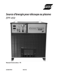
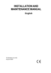
Funcionamiento en paralelo con la red
Paralleling with mains
Conexión y ajustes / Connection and adjustments
Módulo R 726
Module R 726
ATENCION
Aunque su aspecto es idéntico, el módulo R726,
que sustituye al módulo R725,
se conecta de manera diferente y, para su conexión, tal vez requiera transformadores de adaptación.
Véase Modo de empleo :
Sustitución de un módulo R725 por un módulo R726
CAUTION
Wether looking alike the module R725,
the module R726 is differently connected
and may require for its connection
additionnal adapting transformers.
See leaflet :
Replacing module R725 by model R726
Sustitución por un módulo R 726 de los módulos de 2 y 3 funciones siguientes:
Replacement by a module R 726 of the following 2 and 3 functions modules :
Mecánicamente intercambiables
Mechanically interchangeable
R 725
- 3 funciones/functions (Cos ϕ ; U = U)
R 725/100 - 3 funciones/functions (Cos ϕ ; U = U)
R 724
- 2 funciones/functions (Cos ϕ )
no/not
RS 180
- 2 funciones/functions (Cos ϕ )
Reguladores y sistemas de excitación coompatibles con el R 726 :
AVR's and excitation systems being conformable to module R 726 :
2
Reguladores/AVRs
Sistemas de excitación/Excitation system
R 438 LS, R 448, R 449
R 129
R 128.A, R 128.0, R 130
(AREP, SHUNT/RBS)
(ACTR)
(ACTR/RBC)
Módulo R 726
Module R 726
INDEX
INDICE DE CONTENIDO
1 - GENERALIDADES .........................................4
1.1 - Utilización
1.2 - Principio de funcionamiento
1 - GENERAL ........................................................4
1.1 - Purpose
1.2 - Operating principle
2 - ASPECTO . DIMENSIONES ...........................5
2 - OUTLINE DRAWING .......................................5
3 - DESCRIPCION ................................................5
3 - DESCRIPTION .................................................5
3.1 - Margen ajuste potenciómetros exteriores.
3.2 - Precauciones de cableado.
3.1 - Adjustment range of remote pot.
3.2 - Wiring precautions.
4 - ESQUEMA DE CONEXION .............................7
4 - CONNECTION DIAGRAM ...............................7
5 - FUNCIONAMIENTO .......................................8
5 - OPERATION PRINCIPLE ................................8
6 - AJUSTES .....................................................8
6 - ADJUSTMENTS ..............................................8
6.1 - Márgenes y condiciones funcionamiento
6.2 - Proced. de ajuste de puesta en servicio
6.1 - Operating ranges and conditions
6.2 - Adjustment procedure commissionning
7 - PROTECCIONES ESPECIFICAS .................11
7 - SPECIFIC PROTECTIONS ............................11
8 - FUNCIONAMIENTO EN // CON OTRO
ALTERNADOR (AISLADOS DE LA
RED)..............................................................11
8 - PARALLELING WITH ANOTHER GENERATOR (SEPARATE FROM MAINS) ................11
9 - ACOPLAMIENTO A LA RED EN //................11
9 - SYNCHRONISING WITH MAINS WHEN
PARALLELING WITH OTHERS (S)
GENERATORS (S) .......................................11
10 - REGULACION DE COS Ø DE UNA
INSTALACION ............................................11
10 - POWER FACTOR MONITORING
OF A PLANT ................................................11
11 - LOCALIZACION DE FALLOS ....................13
11.1 - Verificación del regulador
11.2 - Verificación del módulo R726
11 - TROUBLE SHOOTING ................................13
11.1 - Checking A.V.R.
11.2 - Checking module R 726
12 - AJUSTES ESTATICOS ..............................13
12 - STATIC ADJUSTMENTS ............................13
13 - REGIMEN DE NEUTRO..............................16
13 - NEUTRAL POINT STATUS .........................16
14 - TENSION FUERA DE MARGENES
ESTANDAR................................................16
14 - VOLTAGE OUT OF STANDARD RANGES..16
15 - ACCESORIOS ...........................................17
15 - ACCESSORIES ...........................................17
16 - ASISTENCIA TECNICA/PIEZAS
DE RECAMBIO............................................17
16 - TECHNICAL ASSISTANCE ........................17
17 - PRINCIPLE CONNECTION DIAGRAMS ....18
17 - ESQUEMAS DE PRINCIPIO........................18
17.1 - Regulador : R 438 LS o R 448 o
R 449 +R 726
17.2 - Regulador : R 129 + R 726
17.3 - Regulador : R 130 o R 128-0 o R 128-A
+ R726
17.1 - A.V.R. : R 438 LS or R 448 or
R 449 + R 726
17.2 - A.V.R. : R 129 + R 726
17.3 - A.V.R. : R 130 ou R 128-0 ou R 128-A
+ R726
18 - USING ONLY THE 2 nd FUNCTION ..........21
18 - UTILIZACION DE LA SEGUNDA FUNCION
SOLA ........................................................21
ATENCION :
CAUTION :
1) CON EL ALTERNADOR EN REPOSO, LA
TENSION DE RED PUEDE ESTAR PRESENTE
EN LAS BORNAS DE DETECCION DE TENSION
DEL MODULO. PELIGRO DE MUERTE.
1) WHEN THE GENERATOR, THE L.L. VOLTAGE OF MAINS MAY BE ON THE VOLTAGE
SENSING TERMINALS OF THE MODULE.
LIFE HAZARD.
2) NO REALIZAR ENSAYOS DIELECTRICOS
SIN DESCONECTAR EL MODULO Y EL REGULADOR ASOCIADO. EXISTE PELIGRO DE DESTRUCCION.
2) DO NOT PROCEED TO HIGH VOLTAGE
TESTS WITHOUT DISCONNECTING (INSULATING) THE MODULE AND ASSOCIATED AVR.
RISK OF DAMAGING COMPONENTS.
3
Módulo R 726
Module R 726
1 - GENERALIDADES
1 - GENERAL
1.1 - Utilización
1.1 - Purpose
El módulo adicional R 726 permite transformar los reguladores de tensión siguientes (siendo la primera FUNCION
principal la REGULACION DE TENSION PRINCIPAL) en
un sistema de regulación denominado de "4 FUNCIONES" :
. siendo la segunda FUNCION la regulación de COS ϕ
(factor de potencia), utilizando un T.I. para funcionamiento
en paralelo con la red.
. siendo la tercera función FUNCION la igualación de las
tensiones antes de acoplamiento (U = U) , la cual,generalmente está asegurada por un sincronizador que acciona el
potenciómetro de ajuste de tensión del regulador de tensión.
. la cuarta FUNCION (asociada a la tercera función) es la
marcha en paralelo con los demás alternadores o con
equipados con el mismo módulo R 726 durante la fase de
igulación de tensión antes del acoplamiento a la red.
The additionnal Module R 726 enables to operate the following automatic voltage regulators (the 1ST FUNCTION
being VOLTAGE REGULATION) into a so said
"4 FUNCTIONS" regulation system :
. the 2nd FUNCTION being the POWER FACTOR
("COS ϕ ") REGULATION, using an additionnal C.T., when
the alternator is paralleling with the mains.,
. the 3rd FUNCTION being the BALANCE (EQUALIZATION) OF VOLTAGES before paralleling (U = U) which is
generally realised by a synchronizer controlling the remote
voltage trimmer of the automatic voltage regulator,
. the 4th FUNCTION (working with the 3rd) is parallel operation with other(s) alternator(s) equpped with the same
module R726 during voltage equalization before paralleling with the mains.
REGULADORES
COMPATIBLES
SISTEMA
DE EXCITACION
VOLTAGE
REGULATOR
EXCITATION
SYSTEM
R 129 / R 128A
compuesta . ACTR
R 129 / R 128A
compound . ACTR
R 130
compuesta . RBC y ACTR
R 130
compound . RBC and ACTR
R 438 LS
AREP o ARPI
R 438 LS
AREP or ARPI
R 448
AREP o ARPI o ATR
R 448
AREP or ARPI or ATR
El módulo debe instalarse cerca del regulador de tensión
(en el interior o en el exterior del alternador).
Va conectado al regulador en lugar del potenciómetro exterior de ajuste de tensión.
El potenciómetro de ajuste de tensión a distancia se
conecta entonces (si así pide) al Módulo R 726 .
The module must be installed close to the voltage regulator
(inside or outside of the machine).
It is connected to the voltage regulator in lieu of the remote
voltage potentiometer of the AVR.
This remote voltage trimmer may be then connected if necessary to the Module R 726.
LAS DEMAS FUNCIONES DEL REGULADOR DE TENSION (PROTECCION EN CASO DE SUBVELOCIDAD,
LIMITACION, SOBREEXCITACION...) SE MANTIENEN.
THE OTHER FUNCTIONS OF VOLTAGE REGULATOR
(UNDERSPEED PROTECTION, EXCITATION LIMIT,
OVERCURRENT...) ARE KEPT.
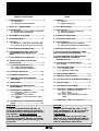
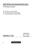
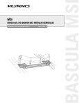
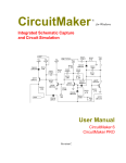
1.2 - Principio de funcionamiento
Esquema funcional
1.2 - Operating principle
Block diagram
R 726 - 4 Funciones
HT/HV
SEÑALIZACION ESTADO Y CONTACTOS
STATUS SIGNALLING AND RELAYING
RED
MAINS
CONTACTOS EXTERIORES
REMOTE CONTACTS
RC1
TP/VT
C1
RC2
(U=U)
(Cos ϕ)
BT(LV)
C2
(L2,L3)
(Cos ϕ )
Alimentación
Supply
(V =U)
P3 STAB
TenSión red
Main voltage
(L2,L3)
UR
+
[ ∑ = UR - UA ]
+
∑
-
UR
P1
UA
AND
ϕ]
MEM
ON
OFF
C2
(L2,L3)
P4 Límite
Cos ϕ
P2
T.I./ C.T. (1A)
IA
Intensidad de línea
Line current
(L1)
(S2)
SALIDA
OUTPUT
Tensión / Voltage
(Rhe 470 Ω)
4
UA
ϕ
(S1)
(S1x S2)
(UR)
(U=U)
Cuarta
función
[ ∑ = ϕ-
+
100V
(VA)
REGULADOR
A.V.R.
Tensión alternador
Generator output
voltage
G
Inductor excitación
ALTERNADOR
Exc field
GENERATOR
Módulo R 726
Module R 726
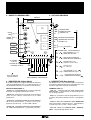
2 - ASPECTO /DIMENSIONES
2 - OUTLINE /DRAWING
115 mm
100 mm
U=U
R 726
T3
10
9
8
7
6
5
4
3
2
1
LED
}
}
ROJO
"U = U"
RED
VERDE
"Cos ϕ"
GREEN
T2
P3
STAB
LIMIT
P4
Cos ϕ
P2 ST1
P1
T1
ST2
R2 R1
SALIDAS DE CONTROL
CONTROL OUTPUT
J1
P5
C1
C2
400 TENSION ALTERNADOR
100 GENERATOR VOLTAGE
(PHASES 2-3)
0
}
S2
S1
}
TI / CT / 1A (FASE 1)
TENSION U = U
VOLTAGE
POTENTIOMETERS
P1
MAS TENSION ALT. (U = U)
MORE GEN VOLTAGE
P2
MAS POTENCIA REACTIVA
MORE REACTIVE POWEREST
P3
ESTABILIDAD (// red)
STABILITY (// with mainS)
P4
Límite de Cos ϕ
P.F. LAG Limit
P6
U
Borna no utilizada
Unused terminal
}
TENSION RED
MAINS VOLTAGE
(PHASES 2-3)
POTENCIOMETROS
1 2 3 4 5 6 7 8 9 10
Al regulador
To A.V.R.
400
100
0
MEDIDAS / SENSING 50/60 Hz
J2
MAS TENSION (en isla)
"Cos ϕ""Cos ϕ"
AJUSTES CONTROL
ADJUSTMENTS / MONITORING
P5 : (-R) = MORE VOLTAGE (single) +
P6 : (+R) =
MAS POTENCIA REACTIVA
MORE REACTIVE POWER
+
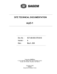
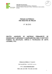
3 - DESCRIPCION (Véase dibujo)
3 - DESCRIPTION (See drawing)
El modelo R 726 posee 2 regletas de bornas de 10 bornas
cada una (FASTON 6,35 mm) J1 y J2 identificadas de 1 a
10, de izquierda a derecha, con las bornas vistas de frente.
The Module R 726 has 2 terminal strips of 10 terminals
consisting in FASTON LUGS (1/4") and mumbered 1 to 10
from left to right when facing the terminal strip.
REGLETAS DE BORNAS J1 :
. bornas 1-2 : SALIDA/MANDO de conexión al regulador
de tensión en lugar del potenciómetro exterior.
TERMINAL STRIP J1 :
. term. 1-2 : OUTPUT FOR VOLTAGE REGULATOR
MONITORING . connected in lieu of remote voltage trimmer of voltage regulator.
. bornas 3-4 : potenciómetro exterior de ajuste de tensión
(véase 3.1 para valores), cortocircuitar si no se utiliza
(puente ST1).
. bornas 5-6 : ENTRADA ORDEN DE FUNCIONAMIENTO "U =U" (en sincronización) - ( contacto seco C1), impedancia total de bucle < 5 ohms /50Hz o 60 Hz.
. bornas 7-8 : ENTRADA ORDEN DE FUNCIONAMIENTO "REGULACION DE COS ϕ " (en paralelo con la red ).
. term. 3-4 : connection of remote voltage trimmer (see 3.1
for values). Short these terminals if no pot. is used (jumper
ST1).
. term 5-6 : INPUT OF COMMAND: "U=U" OPERATION
when synchronising . external contact C1 . total impedance
of circuit loop to be ≤ 5 ohms , 50 Hz or 60 Hz.
. term. 7-8 : INPUT OF COMMAND "COS ϕ REGULATION" when paralleling with the mains.
5
Módulo R 726
Module R 726
(contacto seco C2) ; impedancia de bucle
(< 5 ohms /50Hz o 60 Hz),
External contact C2 ; total impedance of circuit loop to
be ≤ 5 ohms , 50 Hz or 60 Hz,
. bornas 9-10 : potenciómetro exterior de ajuste de cos
ϕ, cortocirtuitar las bornas 9-10 si no se utilizan (puente
ST2).
. term 9-10 : remote pot. to adjust power factor , short these
terminals of external pot. is not used (jumper ST2).
REGLETA DE BORNAS J2
TERMINAL STRIP J2
. bornas 1-2 : ENTRADA MEDICION INTENSIDAD
secundario S1 - S2 de un TI , 5VA cl 1 , IN/1A , en la fase 1
del alternador.
. term. 1-2 : INPUT/CURRENT SENSING ON C.T.
SECONDARY S1 - S2 (5VA cl 1, IN/1 AMP) installed on
phase 1 on generator output,
. borna 3 : vacío.
. term. 3 : not used,
. bornas 4-5-6 : ENTRADA MEDIDA DE TENSION LADO
ALTERNADOR y alimentación módulo, 15 VA :
. borna 4 a fase W3 ("OV"),
. borne 5 a fase V2 ("100V") para tensiones entre fases de
90 a 120 V,
. borna 6 a fase V2 ("400V") para tensiones entre fases de
340 a 440V/50Hz y 380 a 500V/60Hz,
. term. 4-5-6 : INPUT/VOLTAGE SENSING ON GENERATOR SIDE, and power supply to the module, 15 VA :
. term. 4 to phase W3 ("O volt"),
. term. 5 to phase V2 ("100 volt") for L-L voltages bewteen
90 to 120 V,
. term. 6 to phase V2 ("400v") for L-L voltages 340 to
440V/50Hz and 380 to 500V/60Hz,
. borna 7 : no utilizada.
. term. 7 : not used,
. bornas 8-9-10
ENTRADA MEDICION TENSION LADO RED 5VA :
. borna 8 a fase 3 ("OV"),
) idéntico margen
. borna 9 a fase 2 ("100V")
) de tensión
. borna 10 a fase 2 ("400V") ) que en las bornas 4-5-6
. term 8-9-10
INPUT/VOLTAGE SENSING ON
. term. 8 to phase 3 ("0 volt")
. term. 9 to phase 2 ("100V")
. term. 10 to phase 3 ("400V")
Nota : Para tensiones de alternador o de red fuera de los
márgenes de tensión arriba señaladas, deben utilizarse
transformadores de tensión de adaptación (T.P.).
Del mismo modo, si están disponibles T.I. con secundario
de 5A, se requieren T.I. de adaptación 5/1A (véase capítulo Nº 14).
Note : For generator or mains voltages out of the above
mentionned ranges, adapting voltage transformers shall
be used.
As well if C.T. with 5A secondaries are available, adapting
C.T. 5/1A shall be used (see par. 14).
3.1 - Margen de ajuste de los potenciómetros exteriores
3.1 - Adjustment range of remote potentiometers
- P5 : Tensión (3 vatios)
470 Ω : ± 5 %
1 kΩ : ± 10 %
(1)
- P6 : "Cos Ø" (3 vatios)
1 kΩ : ± 5°EL (grados eléctricos) (1)
2,2 kΩ : ± 10°EL (grados eléctricos)
(1) potenciómetro generalmente recomendado
3.2 - Precauciones de cableado
Los hilos que conectan con los contactos C1 y C2 y con los
potenciómetros P5 y P6 deben ser preferiblemente del tipo
de pares trenzados. El posible blindaje debe ir conectado
a masa del alternador en un solo punto.
Intensidad máxima en los hilos: 100 mA, salvo para el
circuito T.I. = 1,1 A.
6
- P5 : Voltage (3 watt)
470 Ω : ± 5 %
1 kΩ : ± 10 %
MAINS SIDE 5VA :
) voltage range
) the same
) as above
(1)
- P6 : "Cos Ø" (3 watt)
1 kΩ : ± 5°EL (electrical degree) (1)
2,2 kΩ : ± 10°EL (electrical degree)
(1) usually recommended
3.2 - Wiring precautions
The leads used for wiring of contacts C1 and C2 and P5 P6
potentiometers shall be preferably twisted (pairs). Eventual shielding shall be connected to the generator frame
(earthing terminal) at a same single point.
Maximum current in all leads except for CT connection
(1,1A) = 100 mA.
Módulo R 726
Module R 726
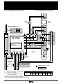
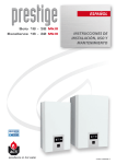
4 - R 726 ESQUEMA DE CONEXION
4 - R 726 CONNECTION DIAGRAM
1
2
3
Y
P2
P1
S2
S1
RED
MAINS
TP / VT
5VA
Y
INDUCTOR EXCITACION
EXCITER FIELD
E-
1
S2
RELE DE EXCITACION
EXCITATION MONITORING
REGULADOR DE TENSION VOLTAGE REGULATOR
J2
R 726
Colocar puentes ST1/ST
si no hay
potenciómetro
Fit jumpers ST1/ST2 if there
is no remote potentiometer
ST1
STZ
10
9
8
7
6
5
4
3
2
1
X Y
VALT
400 V
10 0 V
0V
C2
400 V
100 V
S2
P2
S1
P1
0V
TP / VT
100/110V - 15VA
J1
S2
P2
S1
P1
2
470 Ω
(5Ω / 50 Hz)
R2 R1
U
VALT
TI / CT
… /1A - 3VA
1
TENSION
VOLTAGE
3
S1
ST2
1 2 3 4 5 6 7 8 9 10
2
USUARIO LOCAL
LOCAL USER
E+
P1
ACOPLAMIENTO
PARALLELING
P2
U exc >< MAX
MIN
3
G
P6 Cos ϕ
1000 Ω
(5Ω / 50 Hz)
U SINCRONIZACION
C1 SYNCHRONISING
P5
VALT Relé de tensión alternador
V ALT > MIN
Regulador / A.V.R. RS 128A R 129 R 438 LS R448 R726 R130
Quitar el puente (STZ) o el potenciómetro
Bornas *
Y
5
1
3
3
1
5
existente en el regulador
Terminals
Remove jumper (STZ) or remote pot.
X
4
2
2
2
2
4
on the voltage regulator
* Las bornas de los conectores de los reguladores aparecen
indicadas y numeradas de izquierda a derecha.
* A.V.R.'s terminals are named like numbered from left to right.
R2
R1
7
Módulo R 726
Module R 726
5 - FUNCIONAMIENTO
5 - OPERATION PRINCIPLE
Según el modo impuesto por el estado de los contactos exteriores (designados por C1 para la función "U=U" y C2 para la función "Cos ϕ "). El estado cerrado de los contactos
se señaliza mediante LEDs.
Si no hay tensión en las bornas del alternador (cuando éste
está en reposo o desexcitado), para seguridad del personal, recomendamos cortar la alimentación/detección
de tensión de red, por ejemplo, mediante un relé de tensión
alimentado en el lado alternador (V ALT en el esquema de
principio, V ALT < 25 % de la tensión
nominal).
The module is operating according to the mode imposed by
external contacts (named C1 for equalizer function "U=U"
and C2 for power factor "Cos ϕ " régulation). Closing of the
contacts is signalled by LED.
For the case where the generator is supposed to deliver
no voltage (stopped or disenergized), we recommand for
life safety of personnel to switch off the supply to terminals
7-8-9 of J2 by using for example a voltage relay connected
across generator output (V ALT on principle diagram, V
ALT < 25 % of rated voltage).
C1 = 0 . abierto
C1 = 1 . cerrado
LED rojo
C2 = 0 . abierto
C2 = 1 . cerrado
LED verde
C
1
0
1
C 2
0
1
A
C
B
C
C1 = 0 . open
C1 = 1 . closed
red LED
C2 = 0 . open
C2 = 1 . closed
green LED
A = funcionamiento como REGULACION DE TENSION,
(módulo interno)
B = funcionamiento como IGUALADOR (U=U),
tercera función
C = funcionamiento en REGUL. COS ϕ,
segunda función
A = operating as a VOLTAGE REGULATOR,
(module not acting)
B = operating as a VOLTAGE EQUALIZER (U=U)
3 eme function
C = operating as a POWER FACTOR
REGULATOR (Cos ϕ) 2 nd function
6 - AJUSTES
6 - ADJUSTMENTS
6.1 - Márgenes y condiciones de funcionamiento
6.1 - Operating ranges and conditions
6.1.1 - Segunda función. Regulación de Cos ϕ
Con la conexión indicada, el potenciómetro interno P2 de
ajuste de Cos ϕ permite cubrir desde Cos ϕ = 0,95 AV (desexcitado , absorbiendo potencia reactiva ) a cos ϕ = 0,65
AR (sobreexcitado . entregando potencia reactiva)...
Un potenciómetro P4 (Límite) permite limitar el cos ϕ extremo, p. ej. 0,8 AR.
Se obtiene Cos ϕ = 1 a aproximadamente 1/3 del margen
de ajuste.
Precisión de regulación : ± 2° ELECTRICOS para una
intensidad en el secundario del TI de 1A para variaciones
de tensión de red ± 10%.
± 10° EL.Para una intensidad en el secundario de 0,1 A.
Margen de ajuste del potenciómetro exterior de reglaje de
cos ϕ, P6 (§ 3.2).
6.1.1 - 2nd function . Power factor (cos ϕ) regulation
When connected according to the diagram, the internal potentiometer P2 (Cos ϕ ) enables to adjust the power factor
from P.F. = 0,95 LEAD (underexcited . absorbing reactive
power) to P.F. = 0,65 LAG (overexcited . supplying reactive
power).
Potentiometer P4 (P.F. Limit) enables to set the lowest
Lag. P.F. (i.e. 0,8)
P.F. = 1 is achieved at about 1/3 of adjustment range of
pot. P2.
Accuracy = adjusted phase shift ± 2° ELECTRICAL with a
C.T. secondary current of 1A and mains voltage varying
within ± 10 %.
± 10° EL. with a C.T. secondary current of 0,1 A.
Adjustment range with external pot. P6 (§ 3.2).
6.1.2 - tercera función . Igualación de las tensiones antes del acoplamiento (U=U)
Funciona para una desviación inicial de tensión de hasta el
10 % entre el alternador en modo individual y lared.
El potenciómetro interior de ajuste P1 ((U=U) permite igualar las 2 tensiones antes de del acoplamiento, en lascondiciones normales de sincronización, con una precisión mejor que el 2 % si el reparto de las cargas activas entre los
grupos en paralelo es de ± 5% (cuarta función).
6.1.2 - 3rd function . Equalization of voltages when
synchronising (U = U)
Operates up to 10% voltage difference between the generator running single and the mains voltage.
The internal OFFSET potentiometer P1 (U =U) enables to
equalize the 2 voltages when syncrhonising with a
precision better than 2 %, if then applicable the active load
sharing between the gensets running in parallel is ± 5%
(4th function operating).
6.2 - Procemiento de ajuste de puesta en servicio
6.2 - Adjustment procedure when commissioning
IMPORTANTE :
Aun cuando haya varias máquinas funcionando en paralelo y/o usuarios locales, los ajustes relativos al acoplamiento en paralelo a la red se realizan primero de modo
individual, en vacío (sin usuario local).
IMPORTANT :
Even if there are several alternators supposed to work in
parallel together and/or local users, the adjustments
concerning paralleling with mains must be fulfilled at
first when running single, at no load (without local users).
8
Módulo R 726
Module R 726
6.2.1 - Comprobaciones preliminares
En primer lugar asegurarse que el sistema original de la
máquina se ha ajustado para funcionar sin anomalías en
todo el margen de variación de la tensión de la red para el
cos ϕ deseado (véase modo de empleo correspondiente).
EXCITACION COMPUESTA (ACTR . RBC) : el sistema
compuesto debe estar ajustado para que la tensión en
modo individual pueda ascender a la más alta tensión de
funcionamiento en paralelo con la red (p. ej. 430 V para 400
V nominal). Asimismo, asegurarse de que el regulador de
tensión permite disminuir a la tensión más baja (p. ej ,. 370
V para 400V nominal).
EXCITACION SHUNT + BOOSTER: el booster (transformador de intensidad) debe estar cortocircuitado en el modo de acoplamiento paralelo a la red o su acción debe reducirse mediante un limitador/monitor de booster.
PARA TODOS LOS REGULADORES, verificar el ajuste
del umbral de protección de subvelocidad (o de LAM) :
Debe ajustarse 2 Hz por debajo de la frecuencia más baja
para la cual el sincronizador permite el acoplamiento en
paralelo.
La ESTABILIDAD del regulador de tensión debe ajustarse
en funcionamiento individual.
6.2.1 - Preliminary checks
At first ensure that the excitation system of the machine has
been properly adjusted in order so operate in the whole
voltage variation range of the mains at the requested
power factor.( see advisable leaftet.)
COMPOUND EXCITATION (ACTR . RBC) : the compound
system must be adjusted high enough to be able to operate
single on load at the highest main voltage (i.e. 430 V for
rated 400 V). Check also if the voltage regulator enables to
drop the voltage to the lowest mains voltage level (i.e. 370V
for rated 400 V).
SHUNT + BOOSTER EXCITATION : the booster (current
transformer) shall be either short-circuited when paralleling
with the mains, or its action shall be reduced by a booster
limitor/ monitor.
ON ALL AVRS, check the setting of underspeed protection
or LAM : the threshold level must be adjusted 2 Hz below
the lowest frequency for which the synchronizer allows
paralleling.
The STABILITY of the voltage regulator must be set when
operating single.
6.2.2 - Ajuste de la tensión en funcionamiento en isla
Potenciómetro exterior P5 ajustado en el centro.
Ajustar la tensión del alternador mediante el potenciómetro interno de tensión del regulador.
6.2.2 - Adjustment of voltage in single operation
Remote potentiometer P5 in middle position.
Adjust the generator's output voltage by moving the internal voltage adjust. pot. of the voltage regulator.
6.2.3 - Igualación de las tensiones antes del acoplamiento en paralelo
Aparatos utilizados: tensión red/alternador = voltímetro
numérico 500 V.
Tensión de excitación (Uexc) = voltímetro analógico cal.
30/50 V cc.
Arrancar el grupo electrógeno y ajustar la velocidad para
ponerse en las condiciones normales de acoplamiento en
paralelo.
Cerrar el contacto C1 : el LED rojo debe encenderse.
SI LA TENSION CAE O "AUMENTA HASTA EL LIMITE" :
ERROR DE CONEXION ENTRE EL REGULADOR DE
TENSION Y EL MODULO. PARAR Y PERMUTAR LOS 2
HILOS QUE VAN A PARAR A LOS BORNES 1 y 2 DE LA
REGLETA DE BORNES J1 DEL Módulo R 726 .
Como alternativa, medir la tensión de red y la del alternador
con el mismo voltímetro.
Reducir la desviación actuando sobre el potenciómetro
P1 del módulo (U=U).
Si la tensión del alternador es inestable, entonces, observar la tensión de excitación Uexc y actuar sobre el potenciómetro P3 de ajuste ESTABILIDAD del Módulo R 726 .
6.2.3 - Equalization of voltages when synchronising
Apparatus = mains/generator voltages : digital voltmeter
500 V.
Excitation voltage (Uexc) : analogical index voltmeter 30/50
V DC.
Start the genset and adjust speed to meet normal synchronising conditions.
Close contact C1 : the red LED should light up.
IF THE GENERATOR VOLTAGE DROPS OR RAISES
FAR FROM MAINS VOLTAGE : BAD CONNECTION
BETWEEN THE AVR AND THE MODULE . STOP AND
TRANSPOSE THE 2 LEADS CONNECTED ON TERMINALS 1 and 2 OF TERMINAL STRIP J1 ON MODULE
R 726.
Measure alternatively voltages on mains and generator side with the same voltmeter.
Reduce difference by moving potentiometer P1 (U=U) on
the module.
If the genrator voltage is unstable, adjust on potentiometer P3 on the module, observing the excitation voltage
Uexc, until stabilisation.
6.2.4 - Ajuste del Cos ϕ
Posiciones iniciales :
- potenciómetro exterior de cos Ø (P6) = en el centro,
- potenciómetro interno (P2) situado en 1/4 de su carrera
comenzando a partir de la izquierda,
- potenciómetro P4 (Límite) a fondo, a la derecha
SINCRONIZAR Y ACOPLAR EN PARALELO.
El LED VERDE DEBE ENCENDERSE.
6.2.4 - Power factor (cos ϕ) adjustment
Initial settings :
- external power factor pot. P6 = middle,
- internal power factor pot. P2 = 1/4 of range, when starting
fully anticlockwise.
- internal pot (Limit) P4 fully clockwise.
SWITCH ON PARALLEL WHEN SYNCHRONISED
The green LED should light up.
SI EN EL MOMENTO DEL ACOPLAMIENTO EN PARALELO LA INTENSIDAD DE SALIDA DEL ALTERNADOR
AUMENTA BRUSCAMENTE A UN VALOR ELEVADO O
SI CAE LA TENSION DE EXCITACION, DESACOPLAR
INMEDIATAMENTE :
IF JUST AFTER SWITCHING ON THE LINE CURRENT
RISE TO A RATHER HIGH VALUE OR IF THE
EXCITATION VOLTAGE DROPS, SWITCH OFF IMMEDIATELY AND STOP GENSET :
9
Módulo R 726
Module R 726
WRONG CONNECTION (PHASES) OR REVERSED C.T.
EROR DE CONEXION (FASES) O TI INVERTIDO (PER(TRANSPOSE LEADS COMING FROM C.T. SECONDARY
MUTAR LAS 2 SALIDAS DE SECUNDARIO S1 S2),
S1 S2),
. carga el grupo aumentando la velocidad (+ kW) y ajus. load genset by increasing speed (+ kW) and adjust to
tar a 60 % de la carga nominal (kW),
about 60 % of rated load (kW),
. ajustar al cos ϕ extremo deseado mediante el poten. adjust the requested lowest power factor (cos ϕ ) with
ciómetro internO P 4 (Límite) : aumenta la potencia reacthe
module internal potentiometer P4 (LIMIT) = turning the
tiva entregada (= disminuye el cos ϕ ) girando P2 en sentipot. clockwise increases the supplied reactive power
do horario (véase nota),
(decreases P.F.). See note,
. si no puede obtener el cos ϕ deseado = ERROR DE
. if it is not possible to get the requested P.F. that means
CONEXION (FASES),
there is a CONNECTION MISTAKE (PHASES MARKING),
. INESTABILIDAD := actuar sobre el potenciómetro P3 y,
. IF UNSTABLE : set with STABILITY pot. P3 and eventualen su casO, sobre el potenciómetro ESTABILIDAD del rely with the STABILITY pot. of the voltage regulator.
gulador.
. adjust speed (+kW) to reach 90% of rated kW
. Ajustar (+kW) al 90% de la carga nominal (kW)
. adjust the rated P.F. with pot P2 (cos ϕ )
. Ajustar el cos ϕ nominal con ayuda del potenciómetro P2
NOTE :
(cos ϕ)
1) if neither phase-shift meter or power factor meter are
available, the line current Is has to be calculated to enable
NOTA :
1) si no se dispone de un fasímetro o de un "cosfímetro", es
adjustment of the required P.F. (cos ϕ )
preciso calculaR la intensidad de estátor (IS) que debe
kW : kilowattmeter reading (kW),
obtenerse para el cos ϕ deseado.
IS =
(kW) x 1000
U RESEAU = real reading mains
kW = indicación vatímetro (kW),
voltage (V)
U RED = tensión real red (V)
(A) (Cos ϕ)x 1,73 x (U red)
2) ajuste de cos ϕ = 1 : a cos ϕ = 1 la intensidad de estátor
Is es mínima para una potencia activa constante (kW) :
buscar el mínimo.
2) adjusting P.F. = 1 : at P.F1 the line current Is is minimum when the active load (kW) is kept constant.
Adjust P.F.1 by adjusting the minimum of line current.
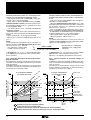
6.2.5 - Variacions típicas de la tensión (o de la intensidad) de excitación
Para identificar o confirmar el estado de funcionamiento del
alternador, resulta útil vigilar la tensión Uexc (o la intensidad) de excitación.
La unidad es la tensión de excitación en vacío U eo nominal
y los valores numéricos corresponden a una máquina con
una reactancia síncrona Xd = 200 %.
6.2.5 - Typical variations of excitation voltage (or
current)
To identify or confirm the operating conditions of the alternator it is useful to measure/monitor the excitation voltage
Uexc (or current).
The unit is the no-load excitation voltage Ueo (for rated
voltage) and datas correspond to an alternator having a
synchronous reactance Xd = 2.00 p.u.
A LA TENSION NOMINAL
AT RATED VOLTAGE
Uexc
Ueo
AG
6
0.
AR
3
(max)
0
75
R
5A
0.9
AD
LE
/
1 AV
5
0.9
1
(min)
P2
3
(max)
A
1
Cos ϕ
2
Cos ϕ
EN VACIO
NO LOAD
1
(min)
Sentido horario
Clockwise
CARGA
LOAD
B
0.8 AR / LAG
AG
/L
}
5
2.2
9
.
1
1.7
2
0.6 AR / LAG
}
2.
4
/L
5
3.
A
.8
AR
A CARGA CONSTANTE
AT CONSTANT LOAD
(kW)
Uexc
Ueo
AG
4
TENSION DE EXCITACION
EXCITATION VOLTAGE
/L
TENSION RED
1MAINS VOLTAGE
B
0
100%
0
(KW)
A SOBREEXCITACION (SOBRECARGA)
B
10
UN - 10%
UN -TEN
R
TENSION
NOMINAL
OVER EXCITATION (OVERLOAD)
SUBEXCITACION (PELIGRO DE PERDIDA DE SINCRONISMO)
UNDER EXCITATION (RISK OF GETTING OUT OF SYNCHRONISM)
UN + 10%
Módulo R 726
Module R 726
7 - PROTECCIONES ESPECIFICAS DE FUNCIONAMIENTO EN PARALELO CON LA RED
7 - SPECIFIC PROTECTIONS REQUIRED
WHEN PARALLELING WITH THE MAINS
. VOLTAGE relay V ALT (alternator output voltage) to cut
. El relé de tensión V ALT (presencia tensión alernador)
permite cortar la detección/alimentación del módulo en la
parada: SEGURIDAD DEL PERSONAL.
. relé de tensión diferencial (O ACOPLADOR)
(U RED . U ALTERNADOR) : prohibición de acoplamiento
en paralelo para una diferencia excesivamente importante.
. relé de MAXIMA EXCITACION (sobrecarga) y MINIMA
EXCITACION (peligro de pérdida de estabilidad), tensión
o intensidad cc,
. relé de MAXI de INTENSIDAD ESTATOR (TERMICA) o
SONDAS TERMICAS (sobrecarga estátor),
. MICROCORTES : todos los medios existentes disponibles deben utilizarse para impedir el reacoplamiento en paralelo o forzar el desacoplamiento en caso de microcorte
de tensión de red.
off the mains supply/sensing to the module when the
generator is stopped : LIFE SAFETY.
. differential voltage (U MAINS . U ALT) relay or synchroniser : prohibiting synchronisation for a too large difference,
. MAXIMUM EXCITATION (overload) or MINIMUM EXCITATION (risk of putting OUT OF SYNCHRONISM) DC
voltage or current relays.
. MAXIMUM LINE CURRENT (THERMICAL) OR THERMAL SENSORS (stator overload),
. MICROBREAKS : all available means shall be applied to
impede reconnection or force switching off in case o f mains
voltage microbreaks.
ATENCION : UN FALSO ACOPLAMIENTO EN PARALELO A LA RED, EN OPOSICION DE FASES, PUEDE DESTRUIR EL ALTERNADOR.
CAUTION : THE LIFE DURATION OF A GENERATOR
PARALLELED WITH MAINS MAY BE ONLY ONE
CONNECTION COMPLETELY OUT OF PHASE.
8 - FUNCIONAMIENTO EN PARALELO CON
UNO O VARIOS ALTERNADORES (EN ISLA)
8 - PARALLEL OPERATION WITH OTHER
GENERATOR(S) (INSULATED FROM MAINS)
Puede emplearse el mismo T.I. que para el módulo R726 =
las entradas de T.I. del regulador y del módulo deben
estar conectadas en serie, respetando el sentido previsto para el regulador.
The same C.T. as for Module R 726 may be used : the
current sensing imputs of AVR and of the module must be
connected in series, with respect to the connection
diagram of the voltage regulator.
NOTA : la detección de tensión de los reguladores para un
T I colocado en la fase 1 debe realizarse entre las fases 2 y
3, igual que para el módulo R726.
NOTE : the voltage sensing of the voltage regulator with a
C.T. located on phase 1, must be connected across phases
2 and 3, as for the module R726.
9 - ACOPLAMIENTO A LA RED DE 2 (O MAS)
ALTERNADORES QUE FUNCIONAN EN PARALELO ENTRE ELLOS - 4ª FUNCION
9 - SYNCHRONISING WITH MAINS 2 (OR
MORE) ALTERNATORS OPERATING IN
PARALLEL TOGETHER - 4th FUNCTION
(Transferencia de carga sin corte)
Con el módulo R726, la fase de sincronización utiliza la tercera función (U = U) - C1 cerrado.
La cuarta función es indisociable de la tercera función y se
pone fuera de servicio en el acoplamiento en paralelo (C2
cerrado).
Si la sincronización se realiza en carga (alternador funcionando en modo individual o en paralelo con otros), la cuarta
función introduce una desviación de tensión de varios %
(1...3) en función de la diferencia entre el cos ϕ ajustado
(segunda función) y el cos ϕ de la carga.
(source change-over without break)
With the module R726, the synchronisation is done by
using the 3rd function (U = U) - C1 closed.
The 4th function cannot be dissociated from the 3rd function : it is only out of duty when paralleling (C2 closed).
Whenever the synchronisation takes place when the alternator is loaded (single or paralleling with other(s)) the
action of the 4th function is so that it introduces a voltage
shift of % (1...3) depending of the gap between the adjusted P.F. (2nd function) and the real load P.F.
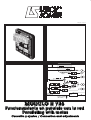
10 - REGULACION DE COS Ø DE UNA INSTALACION ALIMENTADA POR LA RED
10 - MONITORING THE POWER FACTOR OF
A PLANT SUPPLIED BY THE MAINS
- Excitación Shunt o AREP.
El alternador debe estar dimensionado para suministrar toda la potencia reactiva de la instalación (DEBEN ELIMINARSE LOS HABITUALES CONDENSADORES DE
COMPENSACION DE FACTOR DE POTENCIA).
- Shunt or AREP excitation only.
The generator should be rated taking into account the whole reactive power absorbed by the plant (EVENTUAL P.F.
COMPENSATION CAPACITORS MUST BE DISCONNECTED).
Si el dimensionamiento del alternador es insuficiente, además, es preciso instalar y ajustar una resistencia de limitación de RL en serie con el inductor de excitación (RL =
aprox. dos veces la resistencia del inductor), que debe
cortocircuitarse en el caso de funcionamiento en isla.
If the rating of generator is too weak to supply the whole
reactive power of the plant, an adjustable limiting resistor
RL must be connected in series with the exciter field (RL
value : = about 2 times the resitance of exciter field), to
be shorted when the generator operates single.
11
Módulo R 726
Module R 726
Instalar un TI (5VA..../1A) en la fase 1 del lado de llegada
de la red y conectarlo a las bornas 1 y 2 del conector J2 del
Módulo R 726
Fit a C.T. (5 VA .... /1A) on Line 1 on mains side power line
and connect the secondary S1, S2 to terminals 1-2 of term.
strip J2.
RED
MAINS
EL MODULO R 726 REGULA EL COS ϕ
DE LA INSTALACION
VISTA DESDE LA RED
THE MODULE R 726 REGULATES
THE POWER FACTOR OF PLANT
SEEN FROM MAINS
ALIMENTACION RED
TI / CT
… /1A - 5VA
S2
P2
S1
P1
1
y
Cos ϕ
=
PF
x 2 + y2
{
x kVAR
y kW
Cos ϕ
PF
=1
Visto desde la red
3
q kVAR
USUARIO LOCAL
LOCAL USER
CONSUMO LOCAL
LOCAL CONSUMPTION
2
MAINS SUPPLY
( y - z ) kW
Batería de condensadores a eliminar
Compensation capacitors
to remove
S2
P2
S1
P1
2
1
J2
G
RL
2
1
2
x
E+
1
y
E-
3
J1
MODULO
R 726
REGULADOR
AVR
(SHUNT / AREP)
EXCITACION
DIMENSIONAMIENTO DEL ALTERNADOR
RATING OF GENERATOR
{
x kVAR
z kW
Potencia motor
Engine rating
12
{
S (kVA) =
Cos ϕ
PF =
x2 + z2
z
S
de variación de tensión RED
+ Margen
MAINS VOLTAGE variation range
Módulo R 726
Module R 726
11 - LOCALIZACION DE FALLOS
11 - TRACKING THE ORIGIN OF A MISFUNCTION
El sistema completo se supone que ya ha funcionado correctamente.
The complete system is supposed to have been previously
operating satisfactorily.
11.1 - Verificación del regulador
(véase modo de empleo correspondiente)
. desconectar los dos hilos de conexión al Módulo R 726
(bornas 1-2 de J1). Cortocircuitar las dos bornas x-y del regulador previstas para la conexión del potenciómetro exterior del reglaje de tensión.
. hacer girar el alternador en modo individual en vacío a su
velocidad nominal. Si la máquina entrega una tensión regulada (comprobar actuando sobre el potenciómetro interno de reglaje de tensión del regulador), LA AVERIA NO
ESTA RELACIONADA CON EL REGULADOR DE TENSION
11.1 - Checking automatic voltage regulator
11.2 - Verificación del módulo R 726
Asegurarse que a las bornas del módulo llega toda la información necesaria : TENSION DE RED,
11.2 - Checking module R 726
TENSION DE ALTERNADOR, INTENSIDAD DE TI (R < 2
ohmios), CONTACTOS C1 y C2 (R < 5 ohmios) ,POTENCIOMETROS EXTERIORES, y que no está interrumpida
la conexión con el regulador de tensión.
SI EL REGULADOR DE TENSION ESTA EN PERFECTO
ESTADO Y SI LLEGA AL MODULO TODA LA INFORMACION NECESARIA, QUIERE DECIR QUE ESTE ESTA
FALLANDO.
(see aplicable handbook)
. disconnect the 2 wires linking to the Module R 726 (Term.
1-2 of J1) and short the 2 term. x-y of the AVR which are
normally for the connection of a remote voltage adjust. pot.,
. drive the generator at rated speed, operating single at noload. If the machine supplies a regulated voltage (to be
checked by turning the internal voltage adjustment potentiometer) that means that THE MISFUNCTION IS NOT
DUE TO THE VOLTAGE REGULATOR.
Check if all the required informations reach the terminals of the module : MAINS and GENERATOR VOLTAGES, C.T. SECONDARY CURRENT (R < 2 ohms),
CONTACTS C1 and C2 (R < 5 ohms ), REMOTE POTENTIOMETERS , and that connection to the voltage regulator
is not open.
IF THE AVR IS GOOD AND ALL INFORMATIONS INCOME MODULES TERMINALS IS MEANING THAT THE
MODULE IS FAILED.
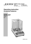
12 - AJUSTES ESTATICOS DEL MODULO
R726
12 - STATIC ADJUSTMENTS ON MODULE
R 726
Véase el esquema y la lista de material.
Los ajustes pueden realizarse con el alternador funcionando en isla en vacío o, en reposo, alimentado por la
red.
Desconectar la conexión del regulador de tensión (bornas
1-2 del conector J1 del módulo).
Conectar a estas bornas un voltímetro preferiblemente digital (cal +/ . 2 V cc),
Cortocircuitar las bornas correspondientes del regulador
(x-y),
Cablear el montaje de ensayo según el esquema.
Los interruptores y conmutadores pueden sustituirse por
enchufes o pinzas aisladas.
La self L (65 mH) sólo es necesaria para preajuste con un
cos ϕ ≠ 1 y para el ajuste de cos ϕ AR Límite.
See diagram and components list here after.
The adjustments may be done either on the generator
operating single at no load, or standing and supplied
by the mains.
Disconnect the 2 wires (OUTPUT) linked to the AVR (on
terminals 1-2 of terminal strip J1 of the module).
Connect to these terminals a DC voltmeter, preferably digital (cal ± 2V DC) and short the 2 terminals x-y of AVR which
were linked to the module,
wire the test assembly according to the diagram,
the switches and c/o switch may be replaced by insulated
plugs or clips.
The choke (reactor) L ( 65mH) is only necessary for a preadjustment at a power factor ≠ 1 et for adjustment of the limit
lowest P.F. LAG.
for P.F. = 1, only a fixed resistor of 27ohms /50 W is necessary.
Precision of such static adjustments is about ± 2% for the
3rd FUNCTION (U=U) and of ± 5° EL for the 2nd FUNCTION (P.F., Cos ϕ ), much depending of the quality of
available voltage transformer.
Para un preajuste con cos ϕ = 1, se requiere tan solo una
resistencia de 27 ohmios/50 W.
La precisión de los ajustes es del orden del ± 2% para la tercera FUNCION (U=U) y de ± 5° EL para la segunda FUNCION (cos ϕ ) en función de la calidad del transformador de
tensión utilizado.
PUEDE EMPLEARSE IDENTICO PROCEDIMIENTO PARA COMPROBAR EL ESTADO DEL MODULO: SI EL
MODULO NO REACCIONA DE LA FORMA DESCRITA,
QUIERE DECIR QUE ESTA FALLANDO.
THE SAME PROCEDURE IS APPLICABLE FOR CHECKING THE CONDITION OF MODULE : IF THE MODULE
IS NOT REACTING AS DESCRIBED, THAT MEANS IT IS
FAILED.
13
Módule R 726
Module R 726
COMPONENTS
MATERIAL UTILIZADO
V1
V2
S0
S1, S2, S3
R1
R2
L
CH
TP
Votímetro digital ± 2V c.c.
Voltímetro ~ cal. 30 V
Interruptor 500 V / 5 A - 2 polos
Interruptores 250 V / 5 A - 1 o 2 polos
Resistencia talón fija 15 Ω / 50 W
Reostato 15 Ω / 50 W
Self 65 mH - 1.5 A - 50 / 60 Hz *
Conmutador 2 posiciones A-B,1 vía, 250V- 5 A
Transfo "de seguridad" 110 - 220 / 24 V - 100 VA
o 220/380 - 24V - 100 VA
* Puede sustituirse por un condensador
C de 150 μF ; en tal caso, permutar S1/S2 del
transformador TP.
"U = U"
ROJO/RED
"Cos ϕ"
VERDE /GREEN
P3 - STAB
P1
U=U
P4 - LIMIT
REGULADOR
DE
TENSION
VOLTAGE
REGULATOR
J2
R 726
LED
P2 - Cos ϕ
ST1
Digital voltmeter range ± 2V DC
AC / RMS voltmeter cal 30 V
500 V / 2 pole switch (5 A)
Switches 250 V / 5 A, 1 or 2 pole
Fixed resistor 15 Ω / 50 W
Rheostat 15 Ω / 50 W
Choke (reactor) 65 mH - 1.5 A - 50 / 60 Hz *
Change over switch 2 positions A - B, 1 way, 250 V - 5 A
"Safety" voltage transformer 110 - 220 / 24 V - 100 VA
or 220/380 - 24V - 100 VA
* May be replaced by a capacitor C of about 150 μF.
Then transpose S1/S2 on voltage transformer TP.
10
9
8
7
6
5
4
3
2
1
0V
S0
400 V
0V
P2
ST2
P1
100 VA
(200-250)/24 V
1 2 3 4 5 6 7 8 9 10
TP
S1
S2
J1
X Y
(350-460V ; 50/60 Hz)
RED o ALTERNADOR
MAINS or GENERATOR
0
1
2
3
(N)
400 V
24V
}
S3
1
Cortocircuitar X,Y
Short-circuit X,Y
2
P5
P6
V2
(UTOT)
Cal ± 2V
V1
(UCOM) S1
15 Ω
S2
FUNCION / FUNCTION
S0 x S1
U=U
Cos ϕ UR
PF =UTOT
Cos ϕ = 1
L
(B)
C4
R2 - 15 Ω
R1
V2
(A)
(UR)
Cos ϕ = 1
(S0 x S1 = S0 y S1 CERRADOS / S0 and S1 CLOSED)
S0 x S1 x S3 x (C4 (A) o/or C4 (B)) = cuarta función /4th function
x C4 (A) Cos ϕ = 1
S0 x S2 x S3
x C4 (B) Cos ϕ = 1
14
Simulación de
circuito medición
intensidad
Simulation of
current sensing
circuit
(S0 x S2 x S3 = S0 y S2 y S3 CERRADOS /
S0 and S2 and S3 CLOSED)
Módulo R 726
Module R 726
AJUSTE DE LA TERCERA FUNCION (U=U)
. Posición inicial de los potenciómetros exteriores (si los
hay) = en el centro,
. cerrar el interruptor S0 (alimentación),
. cerrar el interruptor S1 (U=U),
. el LED rojo se enciende,
.el voltímetro VI indica una tensión UCOM bien de aproximadamente (- 1 V) o bien aproximadamente (+ 1 V),
. girando el potenciómetro P1 (U=U) de izquierda a derecha la tensión UCOM pasa de uno de estos valores extremos al otro,
. el punto de ajuste es la posición de P1 para la cual el voltímetro VI indica una tensión que oscila de (+) a (-) 0,5 V.
ADJUSTMENT OF THE 3RD FUNCTION (U=U)
. initial setting of external ptentiometers (if any) = mid
position,
. switch on S0 (supply switch),
. switch on S1 (U=U Command),
. the red LED lights up.
. the voltmeter V1 indicates a voltage UCOM either about
(-1 volt) or about (+ 1 volt).
By rotating potentiometer P1 (U=U) dockwise from fully
antibockwise position, voltage UCOM triggers from one of
the maximum negative (or reverse) to the other maximum.
The setting position of P1 is that one where the voltmeter V1
indicates a voltage changing from (+) to (-) 0,5 V.
AJUSTE DE LA SEGUNDA FUNCION (COS ϕ)
a) ajuste de P4
.girar los potenciómetros P2 (cos ϕ) y P4 (LIMITE) a fondo a
la derecha.
cerrar el interruptor S2 ( cos ϕ ),
. El LED verde se enciende,
. commutador C4 : B (cos ϕ ≠1),
. cerrar el interruptor S3 (simulación de TI),
. ajustar el cos ϕ límite deseado
. girar el potenciómetro P4 (límite) hasta la posición para la
cual el voltímetro V1 indica una tensión que oscila (+) a (-)
0,5 VOLTIOS.
b) ajuste de P2 (cos ϕ nominal)
C4 en posición B o A : ajustar el cos ϕ nominal deseado y
proceder con P2 como antes con P4.
. abrir todos los interruptores y conectarlos según el esquema.
ADJUSTMENT OF THE 2ND FUNCTION (COS ϕ)
a) adjustment of P4
. set potentiometers P2 (Cos ϕ) and P4 (LIMIT) fully clockwise.
. close switch S2 (COS ϕ FUNCTION COMMAND),
. the green LED lights up,
. change over switch in position : B (PF≠1),
. switch on S3 (circuit simulating C.T.),
. adjust to the required P.F. (no adjustment for P.F. = 1),
. rotate potentiometer P4 (LIMIT) until to reach a position
where voltmeter V1 indicates a voltage tilting from (+) to (-)
0,5 Volt.
b) adjustment of P2 (rated P.F.)
C4 in position B or A - Adjust the required rated P.F.,
proceed with pot P2 as préviously with P4.
. switch off all the switches and reconnect according
relevant diagram.
Cuarta FUNCION
(Funcioanmiento en paralelo durante la igualación de tensión)
No existe ajuste para la cuarta función, pero es posible
asegurarse que está en funcionamiento.
Los ajustes de las funciones segunda y tercera se supone
que se realizan como se ha descrito previamente.
Cerrar S0 y S1 (tercera función U = U).
El voltímetro V1 indica una tensión UCOM comprendida
4th FUNCTION
(Parallel operation with other(s) generator(s) during voltage equalization)
There is no adjustment for the 4th function, but it is possible
to check it is acting.
The adjustment of 2nd and 3rd functions are supposed to
have been performed as described precedently.
Close S0 and S1 (3rd function U = U).
The voltmeter V1 should indicate a voltage UCOM comprised
between + or - 0.5V.
Select with switch C4 a power factor different from
which has been adjusted :
C4 (A) if the power factor has been adjusted or C4 (B)
position ; or C4 (B) if the power factor has been adjusted on
C4 (A) position.
Close S3 : the voltage UCOM indicated by the voltmeter V1
should change to ± 1 Volt, showing tha the 4th function is
acting.
entre + o - 0,5V.
Seleccionar mediante C4 un cos ϕ distinto del cos ϕ
ajustado:
C4 (A) si el cos ϕ se ajusta mediante C4 (B) ; o C4 (B) si el
cos ϕ se ha ajustado mediante C4 (A).
Cerrar S3 : la tensión UCOM indicada por el voltímetro V1 debe cambiar a ± 1 Volt, lo cual indica que está actuando
la cuarta función.
15
Módulo R 726
Module R 726
13 - REGIMEN DE NEUTRO
13 - NEUTRAL LINE STATUS
El régimen de neutro no influye para nada en el funcionamiento del módulo.
Por el contrario, si el alternador tiene un devanado de estátor cuyo paso es distinto de 2/3 y los neutros del transformador y del alternador están conectados directamente
o a través de tierra, es preciso instalar en série con el
neutro una self (reactancia) limitadora de la intensidad
armónica.
Sea X ( ohmios ) la reactancia de la self y L (HENRIOS)
su inductancia X = 314 x L a 50 Hz y 377 x L a 60 Hz.
La intensidad armónica en el neutro Ih será :
U (v)
I h = 0,038 x
(U TENSION ENTRE FASES)
X (ohmios)
The neutral line status has no influence on the module operation.
Adversely, if the winding pitch of the stator winding of
the alternateur is different from 2/3, and the neutral of the
mains transformer and of the generator a connected together either directly or through the carthing circuit, an harmonic current limiting choke (reactor) must be installed
in series with the generator neutral connection.
If X ( ohms ) is the reactance of the choke and L (HENRY) its
inductance : X = 314 x L at 50 Hz and 377 x L at 60 Hz
the harmonic current in neutral line Ih will be =
U(V)
I h = 0,038 x
(U LINE TO LINE VOLTAGE)
X (ohms )
A LA CUAL SE AÑADIRA LA INTENSIDAD HOMOPOLAR
I o DEBIDA A LAS CARGAS DESEQUILIBRADAS.
To this current is adding the zero sequence current I o due
to load unbalance (LN loads):
I NEUTRO =
V (IO)2 + (IH)2
(Amperios eficaces)
I neutral (Amperes R.M.S.) =
V (IO)2 + (IH)2
14 - MEDICION DE TENSIONES E INTENSIDADES FUERA DE MARGENES ESTANDAR
DEL MODULO R 726
14 - MEASUREMENT OF VOLTAGES AND
CURRENTS OUT OF STANDARD RANGES
OF MODULE R 726
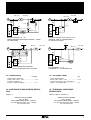
Se emplean transformadores de adaptación dimensionados de la siguiente manera:
Adapting transformers shall be used, rated as follows.
14.1 - Transformadores de tensión (TP)
14.1 - Voltage transformers (V.T.)
Dimensionamiento térmico 50 VA - 50/60Hz
Tensión de primario: tensión disponible en TP o en baja
tensión ≠ 230 - 250 V y 380 - 480 V (100 - 110 - 120 - 500 600V)
Tensión de secundario : 220 o 400 V.
Thermal rating 50 VA - 50/60 Hz.
Primary voltage : the voltage available from measurement
voltage transformer (HV) or low voltages differing from 200
- 250 V or 380 - 480 V (i.e. 100 - 110 - 120 - 500 - 600V)
Secondary voltage : 220 or 400 V.
14.2 - Transformador de intensidad: (T.I.)
14.2 - Current transformer : (C.T.)
3 VA - clase 1
Intensidad de primario: 5A
Intensidad de secundario : 1A
3 VA - classe 1
Primary current: 5A
Secondary current : 1A
14.3 - Referencias de los transformadores
14.3 - References of available transformers
TT : Tensiones de primario 200 - 240 V : ............
500 - 600 V : ............
(Tensión de secundario 100-120 V)
VT : primary voltage
T.I. : Transformador de intensidad : .......................
C.T. : Current transformer : .......................
16
100 - 120 V : ............
500 - 600 V : ............
(Secondary voltage 100-120 V)
Module R 726
Module R 726
AT / HV
BT / LV
G
3 VA
R 726
"U=U"
100V
"Cos ϕ"
1A
C2
400V
100V
100V
REGULADOR
A.V.R.
15 VA
100V
3 VA
C2
5 VA
REGULADOR
A.V.R.
400V
230V
5A
3 VA
MONTAJE BLOQUE - 2F + 3F
TRANSFORMADOR ELEVADOR INTEGRAL - TODAS
LAS FUNCIONES
"Cos ϕ"
400V
1A
MONTAJE BLOQUE - Sólo regulación Cos ϕ
INTEGRAL STEP-UP TRANSFORMER PF REGULATION ONLY
C2
C2
BT / LV
400V
5 VA
400V
100V
R 726
AT / HV
3 VA
REGULADOR
A.V.R.
15 VA
BT / LV
G
3 VA
5 VA
REGULADOR
A.V.R.
AT / HV
100V
1A
BAJA TENSION NO ESTANDAR
OUT OF STANDARD LOW VOLTAGES
15 - ACCESORIOS
5A
400V
R 726
G
AT / HV
G
R 726
BT / LV
400V
1A
3 VA
B.T. ESTANDAR - T.I. 5A
STANDARD LV - CT SECONDARY 5A
15 - OPTIONAL ITEMS
Cantidad
. potenciómetros exteriores 470 Ω / 1kΩ / 2,2kΩ ; 3 W ..............................1 ó 2
. TI 5 VA/secundario 1 A
primario = según la máquina ..........................1 ó...
Qty
. remote potentiometers
470 Ω / 1kΩ / 2,2kΩ ; 3 W ........................... 1 or 2
. current transformer 5 VA/ secondary 1A
Primary : according rating...............................1 or ...
16 - ASISTENCIA TECNICA/PIEZAS RETIRADAS
16 - TECHNICAL ASSISTANCE
SPARE PARTS
Dirigirse a :
Address enquiries and orders to :
MOTEURS LEROY SOMER
Usine de Sillac
16015 ANGOULEME CEDEX - FRANCE
Tel : (33) 05.45.64.43.69 - Telex : 790 044
Fax : 05.45.64.43.24
MOTEURS LEROY SOMER
Usine de Sillac
16015 ANGOULEME CEDEX - FRANCE
Tel : (33) 05.45.64.43.69 - Telex : 790 044
Fax : 05.45.64.43.24
17
60Hz
F1
F2
S1 S2
2 3 4 5
380
220
X2
Z1
X1
Z2
E+
E0
V
W
P2
P4
P3
U=U
C1
J2
W
V
L1
° °
° °
L2
°
°
°
°
Nota
Nota
L3
°
°
°
°
W
RED / MAINS
cos ϕ
C2
P2
° °
° °
S2
P1
V
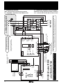
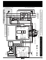
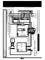
Note : Para el sentido de giro inverso, permutar los hilos de detección de tensión V,W.
For reverse rotation direction, transpose voltage sensing leads to V.W.
Pot. cos ϕ ext. : 1000 Ω
Remote P.F. adjt.
J1
S2
S1
400
100
0
400
100
0
U Alt
1A
T.I / C.T.
S1
U
ALTERNADOR/ALTERNATOR
USUARIO LOCAL / LOCAL USER
Para sentido giro estándar: sentido horario visto lado accionam.
For standard direction of rotation; clockwise seen from Drive End
tercera función / 3 rd function
Sincronización / Synchronizing
U=U
1 2 3 4 5 6 7 8 9 10
Cos ϕ
LIMIT P1
Stab
R 726
Pot. Tensión ext.. : 470 Ω
Remote voltage adjt.
R 438 LS ou/or R 448
o/or R 449 + R 726
Retirado/removed
ST4
1
R 438 LS
o/or
R 448
ou/or
R 449
50Hz
E+
Referencias tensión alternador
Voltage sensing (Generator side)
See internal connection diagram
Véase esquema conexión interno
1 2 3 4 5 6 7 8 9 10
18
ST3
Inductor
de excitación
Exciter field
E-
Bobinados auxiliares AREP
Auxiliary windings
Módulo R 726
Module R 726
17 - ESQUEMAS DE PRINCIPIO
(400V - detección directa) (Sentido de giro horario)
17 - PRINCIPLE CONNECTION DIAGRAMS
17.1 - Regulador : R 438 LS o R 448 o R449+ R 726
17.1 - A.V.R. R 438 LS or R 448 or R 449 + R 726
(400V-direct sensing) - (Direction of rotation : clockwise)
ST4
0
220
380
(STAT)
P1
+ RED
+E
-E
S2
S1
−
+
V
W
P2
P4
P3
P1
U=U
C1
L1
° °
° °
L2
°
°
°
°
L3
°
°
°
°
Nota
Nota
USUARIO LOCAL / LOCAL USER
Nota : Para el sentido de giro inverso, permutar los hilos de detección de tensión V.W
For reverse rotation direction, transpose voltage sensing leads to V,W
RED / MAINS
cos ϕ
C2
P2
° °
° °
S2
P1
W
17.2 - A.V.R. R 129 + R 726
Para sentido giro estándar: sentido horario visto lado accionam.
For standard direction of rotation; clockwise seen from Drive End
J2
W
V
1
2
Pot. cos ϕ ext. : 1000 Ω
Remote P.F. adjt.
J1
S1
S2
400
100
0
400
100
0
U Alt
1A
T.I / C.T.
S1
V
17.2 - Regulador R 129 + R 726
Tercera función / 3 rd function
Sincronización / Synchronizing
U=U
1 2 3 4 5 6 7 8 9 10
Cos ϕ
LIMIT
Stab
R 726
Pot. Tensión ext. : 470 Ω
Remote voltage adjt.
COMPOUND
SISTEMA
Referencias tensión alternador
Voltage sensing (Generator side)
U
ALTERNADOR/ALTERNATOR
Module R 726
R 129 + R 726
Retirado/removed
1 2
P5 (LIM. EXC.)
P2 (VOLT)
P3 (VOLT/Hz)
P6 (STAT. INT.)
P4 (STAB)
R 129
E-
E+
See internal connection diagram
1 2 3 4 5 6 7 8 9 10
Inductor
de excitación
Exciter field
1 2 3 4 5 6 7 8 9 10
Véase esquema conexión interno
Módulo R 726
19
−
+
P2
P4
P3
P1
U=U
C1
L1
° °
° °
L2
°
°
°
°
L3
°
°
°
°
W
Nota
Nota
USUARIO LOCAL / LOCAL USER
Nota :Para el sentido de giro inverso, permutar los hilos de detección de tensión V,W.
For reverse rotation direction, transpose voltage sensing leads to V,W
RED/ MAINS
cos ϕ
C2
P2
° °
° °
S2
P1
V
17.2 - A.V.R. R 130 + R 726
Para sentido de giro estándar: sentido horario visto lado accionam.
For standard direction of rotation; clockwise seen from Drive End
J2
W
V
1
2
Pot. cos ϕ ext. : 1000 Ω
Remote P.F. adjt.
J1
S1
S2
400
100
0
400
100
0
U Alt
1A
T.I / C.T.
S1
U
17.2 - Regulador: R 130 + R 726
Tercera función / 3 rd function
Sincronización / Synchronizing
U=U
1 2 3 4 5 6 7 8 9 10
Cos ϕ
LIMIT
Stab
R 726
Pot. Tensión ext. : 470 Ω
Remote voltage adjt.
COMPOUND
SISTEMA
Referencias tensión alternador
Voltage sensing (Generator side)
See internal connection diagram
ALTERNADOR/ALTERNATOR
Module R 726
R 130 o R 128.0 o R 128 A
+ R 726
R01
S2 S1 0 220 380
3 4 5 6 7 8 9 10
Retirado/removed
ST4
-E +E
1 2
ST1
CUT ST1
CORTAR ST1
R 130
E-
E+
Inductor
de excitación
Exciter field
P1 (STAT. INT.)
Véase esquema conexión interno
1 2 3 4 5 6 7 8 9 10
20
P5 (VOLT/Hz)
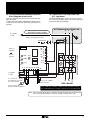
Hay que señalar que no se debe conectar los cables 4 y 5 del regulador R130 como indicado en la figura, sino que hace falta invertirlos para conectar el módulo R726. Solo se deben invertir los
cables del regulador R130.
It is necessary to point out that wires 4 and 5 of the R130 regulator have to be inverted with regard to the drawing in case of connection to the R726 module. This inversion of wires only applies to
the R130 regulator.
Módulo R 726
Módulo R 726
Module R 726
18 - UTILIZACION DE LA SEGUNDA FUNCION
SOLA (Regulación de Cos Ø).
18 - USING ONLY THE 2nd FUNCTION
(P.F. regulation).
Véase los esquemas anteriores para la conexión del regulador de tensión.
La alimentación del módulo "EN SERVICIO" debe realizarse durante la sincronización (antes del acoplamiento en
paralelo)
See preceeding diagrams for the connection of A.V.R.
The connection of supply "ON" has to be done during synchronization (before paralleling)
Véase esquema conexión interno
ALTERNADOR/ALTERNATOR
U
V
W
See internal connection diagram
Al regulador
To AVR
Referencia tension alternador
Voltage sensing (Generator side)
1A
ON
400
100
0
utilizadas
terminals
Stab
U=U
P3
LIMIT P1
P4
400
100
0
S2
S1
Cos ϕ
1
V
° °
° °
W
J2
P2
P2
°
°
°
°
°
°
°
°
L2
L3
C2
cos ϕ
1 2 3 4 5 6 7 8 9 10
J1
A regulador
° °
° °
To AVR
Pot. Tensión ext. : 470 Ω
Eventualmente controlado
por el sincronizador
Remote voltage adjt.
Synchronizer when applicable
Pot. cos ϕ ext. : 1000 Ω
Remote P.F. adjt.
L1
USUARIO LOCAL / LOCAL USER
Unused
S2
Nota
2
1 2 3 4 5 6 7 8 9 10
R 726
P1
T.I / C.T.
EN SERVICIO
Bornas no
S1
RED / MAINS
Para sentido giro estándar: sentido horario visto lado accionam.
For standard direction of rotation; clockwise seen from Drive End
Nota : Para el sentido de giro inverso, permutar los hilos de detección de tensión V.W.
For reverse rotation direction, transpose voltage sensing leads to V,W.
21
Notas / Notes
MOTEURS LEROY-SOMER 16015 ANGOULÊME CEDEX - FRANCE
338 567 258 RCS ANGOULÊME
S.A. au capital de 62 779 000 €
www.leroy-somer.com