1
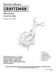
Operator's
Manual
I:Rl FI'SlVl N
208cc Engine
Front Tine Tiller
Model No. 247.29934
*
*
*
*
*
*
CAUTION: Before using
this product, read this
manual and follow all
safety rules and operating
instructions.
Sears Brands
Management
Corporation,
Hoffman
Estates,
SAFETY
ASSEMBLY
OPERATION
MAINTENANCE
PARTS LIST
ESPANOL
iL 60179, U.S.A.
Visit our web site: www.craftsman.com
FORMNO. 769-05511C
2/1/2011
WarrantyStatement
..................................
Pace2
SafetyInstructions
....................................
Paces 3-6
SafetyLabels............................................
Pace7
Assembly
..................................................
Paces 8-10
Operation
..................................................
Paces 11-17
ServiceandMaintenance
.........................
Paces 18-22
Off-Season
Storage..................................
Pace 23
CRAFTSMAN
Troubleshooting
........................................
Page24
PartsList...................................................
Page26-37
LabelMap.................................................
Page38
RepairProtection
Agreement
...................
Page41
Espa_ol
.....................................................
Page42
ServiceNumbers......................................
BackCover
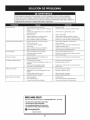
TWO YEAR FULL WARRANTY
FORTWO YEARSfrom the dateof purchase,this productiswarrantedagainstanydefectsin materialor workmanship.Defectiveproductwill
receivefree repairor free replacementif repairis unavailable.
For warranty
coverage
This warranty
•
details to obtain repair or replacement,
covers ONLY defects
visit the web site: www.craftsman.com
in material and workmanship.
Warranty
coverage
does NOT include:
Expendableitemsthat can wearoutfrom normalusewithin thewarrantyperiod,such as
blades,tines,or belts.
Productdamageresultingfrom userattemptsat productmodificationor repairor caused by productaccessories.
Repairsnecessarybecauseof accidentor failureto operateor maintainthe productaccordingto all suppliedinstructions.
Preventivemaintenance,or repairsnecessarydue to improperfuel mixture,contaminatedor stalefuel.
This warrantyis void if this productis ever usedwhileprovidingcommercialservicesor if rentedto anotherperson.
This warrantygivesyou specificlegal rights,and you mayalso haveotherrightswhich vary from stateto state.
Sears Brands
Management
EngineSeries:
208cc
EngineOil Type:
EngineOil Capacity:
Fuel:
10w30
20 ounces
UnleadedGasoline
SparkPlug:
F6RTC
SparkPlugGap:
.030"
© Sears Brands,LLC
Corporation,
Hoffman
Estates,
IL 60179
Model Number.................................................................
Serial Number .................................................................
Dateof Purchase.............................................................
Recordthe modelnumber,serialnumber
and dateof purchaseabove
2
This machinewas built to be operatedaccordingto the safe operation practicesin this manual.As with any type of powerequipment,
carelessnessor error on the part of the operatorcan resultin
seriousinjury.This machineis capableof amputatingfingers,hands,
toes and feet and throwingdebris. Failureto observethe following
safetyinstructionscouldresultin seriousinjuryor death.
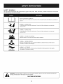
This symbolpointsout importantsafetyinstructionswhich,if not
followed,couldendangerthe personalsafetyand/orpropertyof
yourselfand others. Readand followall instructionsin this manual
beforeattemptingto operatethis machine.Failureto complywith
these instructionsmay resultin personalinjury.Whenyou seethis
symbol,HEEDITS WARNING!
CALIFORNIA
PROPOSITION
65
Your Responsibility=Restrict the useof this powermachineto
personswho read,understandand follow thewarningsand instructions in this manualand on the machine.
EngineExhaust,someof its constituents,and certainvehicle
componentscontainor emit chemicalsknownto Stateof California
to cause cancerand birthdefects or other reproductiveharm. Battery posts,terminals,and relatedaccessoriescontainleadand lead
compounds,chemicalsknownto the Stateof Californiato cause
cancer and reproductiveharm.Washhandsafter handling.
SAVETHESEINSTRUCTIONS!
TRAINING
PREPARATION
•
Read,understand,and followall instructionson the machineand
in themanual(s)beforeattemptingto assembleand operate.
Keepthis manualin a safe placefor futureand regularreference
and for orderingreplacementparts.
•
•
•
Readthe Operator'sManualand followall warningsand safety
instructions.Failureto do so can resultin seriousinjuryto the
operatorand/or bystanders.Forquestions,call 1-800-4MY-HOME.
Be familiarwith all controlsand their properoperation.Knowhow
•
to stop the machineand disengagethemquickly.
Neverallowchildrenunder 14 yearsof age to operatethis
machine.Children14and over shouldreadand understandthe
instructionsand safe operationpracticesin this manualand on
•
the machineand be trainedand supervisedby an adult.
•
•
•
Neverallowadultsto operatethis machinewithoutproper
instruction.
•
Keepbystanders,pets,and childrenat least 75 feetfrom the
machinewhile it is in operation.Stopmachineif anyoneenters
the area.
•
•
•
Alwayswear safetyglassesor safetygogglesduring operation
and while performingan adjustmentor repair,to protectyour
eyes.Thrownobjectswhich ricochetcan cause seriousinjuryto
the eyes.
Wearsturdy,rough-soledwork shoesand close-fittingslacksand
shirts.Loosefittingclothesor jewelrycan be caughtin movable
parts.Neveroperatethis machinein bare feet or sandals.
Beforestarting,checkall bolts and screwsfor propertightnessto
be surethe machineis in safe workingcondition.Also,visually
inspectmachinefor any damageat frequentintervals.
Disengageclutchleversand shift (if provided)into neutral("N")
beforestartingtheengine.
Neverleavethis machineunattendedwith the engine running.
•
Neverattemptto make anyadjustmentswhilethe engineis
running,exceptwherespecificallyrecommendedin the operator's
manual.
•
Maintainor replacesafetyand instructionslabels,as necessary.
Neverrun an engine indoorsor in a poorlyventilatedarea.Engine
exhaustcontainscarbonmonoxide,an odorlessand deadlygas.
3
Thoroughlyinspectthearea wherethe equipmentis to be used.
Removeall rocks,bottles,cans,or otherforeignobjectswhich
could be pickedup or thrownand cause personalinjuryor
damageto the machine.
Safe Handling of Gasoline:
Toavoidpersonalinjuryor propertydamageuseextremecare in
handlinggasoline.Gasolineis extremelyflammableand the vaporsare
explosive.Seriouspersonalinjurycan occurwhengasolineis spilled
on yourselfor yourclotheswhichcan ignite.Washyour skin and
changeclothesimmediately.
•
•
Use onlyan approvedgasolinecontainer.
Neverfill containersinsidea vehicleor on a truckor trailerbed
with a plasticliner.Alwaysplacecontainerson the groundaway
fromyour vehiclebeforefilling.
•
Whenpractical,removegas-poweredequipmentfromthe truck
or trailerand refueliton the ground.If this is notpossible,then
refuelsuchequipmenton a trailerwith a portablecontainer,rather
thanfrom a gasolinedispensernozzle.
Keepthe nozzlein contactwith the rimof the fuel tank or
containeropeningat all times untilfuelingis complete.Do not use
a nozzlelock-opendevice.
•
•
•
•
•
•
•
•
•
Extinguishall cigarettes,cigars,pipesand other sourcesof
ignition.
Neverfuel machineindoors.
•
•
•
•
•
bottomof filler neck to allowspacefor fuel expansion.
Replacegasolinecapand tighten securely.
If gasolineisspilled,wipe itoff theengineand equipment.Move
unitto anotherarea.Wait5 minutesbeforestartingthe engine.
To reducefire hazards,keepmachinefreeof grass, leaves,or
otherdebrisbuild-up.Cleanup oil or fuel spillageand removeany
fuel soakeddebris.
Neverstorethe machineor fuel containerinsidewherethereis an
•
•
•
•
openflame,spark or pilotlightas on a water heater,space heater, •
furnace,clothesdryer or othergas appliances.
•
OPERATION
•
•
•
•
•
•
•
•
After strikinga foreignobjector ifyour machineshouldstart makingan unusualnoiseor vibration,immediately
shut the engineoff.
Disconnectthe sparkplug wire,ground itagainstthe engineand
performthe followingsteps:
a. Inspectfor damage.
b.
c.
Neverremovegas capor add fuel whilethe engineishot or running.Allowengineto cool at leasttwo minutesbeforerefueling.
Neveroverfill fueltank. Fill tankto no morethan1/2inchbelow
•
Lookdownand behindand usecare whenin reverseor pulling
machinetowardsyou.
Start the engineaccordingto the instructionsfoundinthis manual
and keepfeet well awayfromthe tines at all times.
Do not puthandsor feet near rotatingparts.Contactwith the
rotatingpartscan amputatehandsand feet.
Do notoperatemachinewhileunder the influence
of alcoholor
drugs.
•
Repairor replaceanydamagedparts.
Checkfor anyloose partsand tightento assurecontinued
safe operation.
Disengageall clutchlevers(if fitted)and stopengine beforeyou
leavethe operatingposition(behindthe handles).Wait until
the tines cometo a completestop beforeuncloggingthe tines,
makingany adjustments,or inspections.
Neverrun an engineindoorsor in a poorlyventilatedarea.Engine
exhaustcontainscarbonmonoxide,an odorlessand deadlygas.
Mufflerand enginebecomehot and cancause a burn.Do not
touch.
Usecautionwhentillingnear fences,buildingsand underground
utilities. Rotatingtines can causepropertydamageor personal
injury.
Donot overloadmachinecapacityby attemptingto till soil too
deep at too fastof a rate.
If the machineshouldstart makingan unusualnoiseor vibration,
stop the engine,disconnectthe spark plugwire and groundit
againstthe engine.Inspectthoroughlyfor damage.Repairany
damagebeforestartingand operating.
Keepall shields,guards,and safetydevicesin placeand operating properly.
Neverpick up or carry machinewhilethe engineis running.
Useonly attachmentsand accessoriesapprovedby the manufactureras listedin the PartsList pagesof this operator'smanual.
Failureto do so can resultin personalinjury.
If situationsoccur whichare notcoveredinthis manual,use care
and good judgement.ContactCustomerSupportat 1-800-4MYHOMEfor assistanceand the nameof thenearestservicedealer
MAINTENANCE
Neveroperatethis machinewithoutgood visibilityor light.Always
be sureof yourfootingand keepa firm hold on the handles.
Keepbystandersawayfrom the machinewhileit isinoperation.
Stopthe machineif anyoneentersthe area.
Be carefulwhentilling in hard ground.Thetines maycatchin the
groundand propelthe tillerforward.If this occurs,let go of the
handlebarsand do not restrainthe machine.
•
Keepthe machine,attachmentsand accessoriesin safeworking
order.
•
Allowthe machineto coolat leastfive minutesbeforestoring.
Nevertamperwith safetydevices.Checktheirproperoperation
regularly.
Checkboltsand screwsfor propertightnessat frequentintervals
to keepthe machineinsafeworkingcondition.Also,visually
inspectmachineforany damage.
Beforecleaning,repairing,or inspecting,stop the engineand
makecertain thetines and all movingparts havestopped.
Disconnectthe sparkplug wireand grounditagainstthe engineto
preventunintendedstarting.
•
Exerciseextremecautionwhenoperatingon or crossinggravel
surfaces.Stayalert for hiddenhazardsor traffic. Do notcarry
passengers.
Neveroperatethe machineat hightransportspeedson hard or
slipperysurfaces.
Exercisecautionto avoidslippingor falling.
•
4
& STORAGE
•
Do notchangethe enginegovernorsettingsor over-speedthe
engine.Thegovernorcontrolsthemaximumsafeoperatingspeed
of engine.
Maintainor replacesafetyand instructionlabels,as necessary.
Followthis manualfor safe loading,unloading,transporting,and
storageof this machine.
Alwaysreferto theoperator'smanualfor importantdetailsif the
machineis to be storedforan extendedperiod.
If thefuel tank hasto be drained,do this outdoors.
Observeproperdisposallawsand regulationsfor gas,oil, etc.to
protectthe environment.
Accordingto the ConsumerProductsSafetyCommission(CPSC)
and the U.S.EnvironmentalProtectionAgency(EPA),this product
hasan AverageUsefulLifeof seven(7) years,or 130 hoursof
operation.At the endof theAverageUsefulLifehavethe machine
inspectedannuallyby an authorizedservicedealerto ensurethat
all mechanicaland safetysystemsare workingproperlyand not
wornexcessively.Failureto do so can resultin accidents,injuries
or death.
DO NOT MODIFY
ENGINE
Toavoidseriousinjuryor death, do not modifyenginein anyway.
Tamperingwith the governorsettingcan leadto a runawayengineand
causeit to operateat unsafespeeds.Nevertamperwith factory setting
of enginegovernor.
NOTICE
REGARDING
EMISSIONS
Engineswhich are certifiedtocomplywith Californiaand federal
EPAemissionregulationsfor SORE(SmallOff RoadEquipment)are
certifiedto operateon regularunleadedgasoline,and mayinclude
the followingemissioncontrol systems:EngineModification(EM),
OxidizingCatalyst(CO), SecondaryAir Injection(SAI)and ThreeWay
Catalyst(TWO)if so equipped.
SPARK
ARRESTOR
This machineis equippedwith an internalcombustionengineand
shouldnotbe usedon or near anyunimprovedforest-covered,
brushcoveredor grass-coveredland unlessthe engine'sexhaust
systemis equippedwith a sparkarrestormeetingapplicablelocal or
statelaws (if any)
If a sparkarrestoris used, it shouldbe maintainedin effectiveworking
order by theoperator.Inthe State of Californiathe aboveis required
bylaw (Section4442 of the CaliforniaPublicResourcesCode). Other
statesmayhavesimilarlaws. Federallawsapplyon federallands.
A spark arrestorfor the muffleris availablethroughyournearestSears
Partsand RepairServiceCenter.
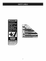
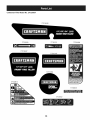
SAFETY
SYMBOLS
This pagedepictsand describessafetysymbolsthat mayappear on this product. Read,understand,and followall instructionson the machine
beforeattemptingto assembleand operate.
i
READ THE OPERATOR'S MANUAL(S)
Read, understand,
i
and follow
all instructions
in the manual(s) before
attempting
to assemble
and
operate
WARNING--
ROTATING TINES
Do not put hands or feet near rotating
hands and feet.
WARNING--
parts. Contact with the rotating
parts can amputate
parts. Contact with the rotating
parts can amputate
ROTATING TINES
Do not put hands or feet near rotating
hands and feet.
WARNING--GASOLINE
IS FLAMMABLE
Allow the engine to cool at least two minutes
WARNING--
CARBON MONOXIDE
Never run an engine indoors
monoxide,
WARNING--
or in a poorly ventilated
area. Engine exhaust contains carbon
an odorless and deadly gas.
HOT SURFACE
Engine parts, especially
and muffler
before refueling.
the muffler,
become extremely
hot during
operation.
Allow engine
to cool before touching.
WARNING: YourResponsibility--Restrictthe use of this powermachineto personswho read,understandand followthe
warningsand instructionsin this manualand on the machine.
SAVETHESEINSTRUCTIONS!
6
Fire Prevention Requirements,
7
f
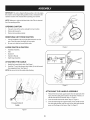
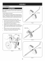
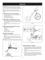
IMPORTANT:This unit isshippedwithoutgasolineor oil inthe engine.
Be certain to serviceenginewithgasolineand oil as instructed
in the
Operationsectionof this manualbeforeoperatingyourmachine.
NOTE:Referenceto rightand left hand sideof the Tillerisobserved
fromthe operatingposition.
OPENING
CARTON
1.
Cut eachcornerof the cartonverticallyfromtop to bottom.
2.
3.
Removeall looseparts.
Removeloosepackingmaterial.
REMOVING
1.
2.
UNIT FROM CARTON
Use the handlebarto lift and pullthe tiller backwardsto a flat
area.Checkthecarton thoroughlyfor looseparts.
Be sure notto kinkthe forwardclutchcable.
J
LOOSE
•
•
HandlebarAssembly
Tiller
•
•
EngineOil
Operator'sManual
•
DepthGage Assembly
ATTACHING
1.
Figure2
PARTS IN CARTON
f
THE CABLE
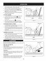
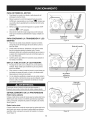
Identifythe forwardclutchcable. See Figure1.
2.
Hookthe "Z" end of the forwardclutchcable(A) intothe forward
fineengagementlever.See Figure2.
NOTE:Be sure notto kink the cablewhileattaching.
/
/
/
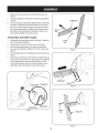
Figure3
ATTACHING
1.
2.
Forward
3.
Clutch
Cable
J
Figure1
8
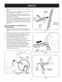
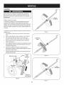
THE HANDLE
ASSEMBLY
Removethe hexbolt and cuppedwasherfrom the rightside of the
frame.Holdthe cableguide bracketon the left sideof frameas it
will fall whenthe boltis removed.Step 1 in Figure3.
Insertthe handle intothe tillerframe.Step2 in Figure3.
Insertthe bolt throughthe cuppedwasher,frame,handleand into
the cableguide bracket(notethe notch in the cableguide bracket
goes overtheflangeon theframe.)Step3 in Figure3.
4.
5.
6.
7.
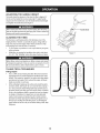
Tightenthe boltsecurelyafter securingthe handlebrace.See
Figure4.
Locatethecarriagebolt, bell washerand hand knobpackedwith
yourtiller.
Insertthe carriagebolt throughthe weldedbracketon the handle,
bell washer,handlebraceand intothe hand knob.See Figure4.
Selectone of the threehandleheightpositions(threenotchesin
the weldedhandlebracket)and tightenthe hand knobto secure
the handlein the desiredposition.See Figure4. Returnto the
lowerhandleand tightenthe hexbolt securely.
ATTACHING
1.
2.
3.
4.
5.
Tail Bracket
THE DEPTH
Depth
Stake
GAGE
Disassemblethedepthgage assembly.See Figure5. Retainthe
pin and clip for laterreassembly.
Removethetwo screwsfrom the tail bracket.See Figure6.
Insertthe depthgage bracketintothe frameand reinstallthe
two screwsremovedearlier.Tightenthe hexbolts securely.See
Figure6.
Pin
Figure5
Insertthe depthstakeintothe depthgage bracketassembly.See
Figure7.
Securethe pin with the clip removedearlier.Thedepth stakecan
be placedat variouspositions.Forsetuppurposesit is suggested
that the depthstakebe assembledwith the stakejust above
or levelwith the groundsurface.Forfurther instructionson the
DepthStake referto the OperationSectionof this manual.
..................
/,
.....................
Tail Bracket
Hand Knob
Figure6
f
(:otter
Pin
_Clevis
Pin
J
Figure7
9
f
ADJUSTMENTS
Prior to operatingyour tiller,carefullyreadand followall instructions
below.Performall adjustmentsto verifyyourtiller isoperatingsafely
_andpropery.
Checkthe adjustmentof the wheels:
Thetiller isshippedwith the wheelsadjustedso thatthe machinesits
level.Thewheels needto be adjustedto meetyourtillingneedsbefore
operation.This adjustmentismadeby removingtheclevis pin fromthe
wheelyokeand raisingthe wheelsto thedesiredheight.See Figure8.
Checkthe adjustmentof the forwardclutchcableas follows:
1.
2.
3.
Disconnectand groundthe spark plugwire againsttheengine.
Adjustthe cableby looseningthe hexnut. See Figure9.
Turnthe cablecollar sectionone or two turnsto increaseor
4.
decreasetensionon thecable. See Figure10.
Retightenthe lock nut againstthe cablecollar.See Figure11.
J
Figure9
5.
Withthe forwardfine engagementhandlein the neutral(released)
position,pull the starterrope severaltimes. Thetines shouldnot
turn.
6.
If they turn forwardor in reverse,adjustthe clutchcableto
decreaseor increasetensionusingthe previousstepslisted.
Checkagain for correcttensionon the clutchcable.
7.
f
Wheel Yoke
Pin
\
Figure10
f
Nut
Depth
Stake
J
Figure8
J
Figure11
10
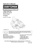
f
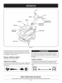
Muffler
Forward
Engagement
--
Handle
Tine
Lever
Height
Adjustment
Fuel Ca
Oil Fill Cap
& Dipstick
_th Stake
Tiller Tines
.J
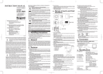
Figure12
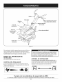
Nowthat youhaveset up yourtillerfor operation,get acquaintedwith
its controlsand features.Theseare describedon the next two pages
and illustratedon this page.This knowledgewill allowyou to useyour
newequipmentto its fullestpotential.
RECOIL
STARTER
The operationof anytiller can resultin foreignobjectsbeingthrown
intothe eyes,which can damageyoureyesseverely.Alwayswear
safetyglassesduringoperationor whileperforminganyadjustments
or repairs.
HANDLE
This handleis usedto startthe engine.
THROTTLE
CHOKE
CONTROL
The chokecontrolis foundon the sideof the engineand is activated
by movingthe leverto the CHOKEposition.Activatingthe choke
controlclosesthe chokeplateon the carburetorand aids in startingthe
engine.
CONTROL
Thethrottlecontrolis locatedon the sideof the engine.It regulatesthe
spreadof the engineand will shut off theenginewhen movedintothe
STOPposition.
CHOKE
Meets ANSi Safety Standards
CraftsmanTillersconformto the safety standardof the AmericanNationalStandardsInstitute(ANSI).
11
RUN
AiR FILTER
DEPTH
STAKE
Theair filter is a deviceon the engineair intakethat preventsdust and
dirt enteringthe engine.See Figure12.
The depthstakecontrolsthe tillingdepth.See Figure12.
HANDLEBAR
MUFFLER
HEIGHT
ADJUSTMENT
Engineexhaustexitsthe enginevia the muffler.See Figure12.
The handleheightmay be adjusted.Loosenthe knobto changethe
position.Tightenhardwarewhencomplete.See Figure12.
OIL FILL CAP & DIPSTICK
TINES
Engineoil levelcan be checkedand oil addedthroughtheoil fill. See
Figure12.
NOTE:This unitwas shippedWITHOUToil inthe engine.Oil is
includedin the plasticbag packedwith the manualin with the unit.
Add theoil as directedin theGas & Oil Fill Up section.Checkthe oil
levelbeforeeachoperationto ensureadequateoil is inthe engine.
Forfurther instructions,
referto the stepsin the EngineMaintenance
sectionof this manual.
Tillingtines are usedto cultivate,furrowand prepareyourgardenfor
seeding.See Figure12.
FORWARD
TINE ENGAGEMENT
LEVER
Theforwardtine engagementlevercontrolsthe engagementof the
tines.Releasethe leverto stop the tines.See Figure12.
12
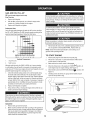
GAS AND OIL FILL-UP
Oil (one bottle shipped with unit)
FirstTime Use
1.
2.
Removeoil fill dipstick.
With the tilleron levelground,usea funnelto emptyentire
contentsofoil bottle providedintothe engine.
3.
Replaceoil fill dipstickand tighten.
Alcoholblendedfuels (calledgasoholor usingethanolor methanol)
canattract moisturewhich leadsto separationand formationof acids
duringstorage.Acidicgas can damagethe fuel systemof an engine
whilein storage.
Toavoidengineproblems,the fuel systemshouldbe emptied
beforestoragefor 30 days or longer.Drainthegas tank,start the
engineand let it run untilthe gastank, fuellinesand carburetorare
empty.Usefresh fuel next season.See STORAGEInstructionsfor
additionalinformation.
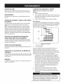
Subsequent Uses
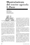
Only usehigh qualitydetergentoil ratedwith APIserviceclassification SF,or SG.Selectthe oil'sSAE viscositygradeaccordingto the
expectedoperatingtemperature.Followthe chart below.
Imml mira
10w
_
mm
_
)0W
Neveruseengineor carburetorcleanerproductsin the fueltank or
permanentdamagemayoccur.
m?0
mmm mmm B30
3.
Fillfuel tank with clean,fresh,unleadedregulargasolineonly. Do
not usegasolinecontainingMETHANOL.Replacefuel cap.
NOTE:Checkthe fuellevelperiodicallyto avoid runningout of
gasolinewhileoperatingthe tiller.
40 I_
20w40.20w50
I
I
15w40, 15w50 ml
®
_
_
_
_
.,i,_
m_,R, ram= .,,,,=._ ,,,,,,,,,l_
v
m..-
10w40
[
P"
10w30
(°C)-300
(°F)-20 o
iw,_mm_
-200 -100 0'_
0o
Ambient
1.
SingleViscosity
2.
MultiViscosity
_m
TO START
100 200 300 400
200 400 60o 800
1000
1.
2.
Temperature
3.
Althoughmulti-viscosityoils (5W30, 10W30,etc.)improvestarting
in coldweather,theywill result in increasedoil consumptionwhen
usedabove32°F.Checkyourengineoil levelmorefrequentlyto avoid
possibleenginedamagefrom runninglowon oil.
1.
2.
3.
Checkthe oil levelmakingcertain notto rubthe dipstickalong
the insidewallsof the oil fill tube.This would resultin a false
Attachspark plugwire and rubberbootto sparkplug.
Filltank to no morethan 1/2inch belowbottomof filler neckto
providespacefor fuelexpansion.
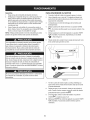
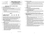
Makesurethe tineclutchcontrol isdisengaged.
4.
Movethechoke leveron the engineto CHOKEI'_1 position.(A
warm enginemay not requirechoking.)See Figure13.
5.
Movethrottlecontrolto START/RUN(Rabbit)_1_ position.See
Figure13.
Standingon the sideof the unit, graspstarterhandleand pull
ropeout untilyou feela drag.
6.
dipstickreading.Wipedipstickcleanwith cloth. Replacedipstick
into theoil fillerneck, butdo not screwit in. Removeand check
oil level.Refillto FULLmarkon dipstick,if necessary.Capacityis
approximately20 oz. Overfillingwill causethe engineto smoke
profuselyand will resultin poorengine performance.
Replaceoil fill dipstickand tighten.
Keepoil levelat FULL.Runningthe enginewith too little oil can
result in permanentenginedamage.
ENGINE
f
Useextremecarewhenhandlinggasoline.Gasolineis extremely
flammableand the vaporsare explosive.Neverfuel machineindoors
or whilethe engineis hotor running.Extinguishcigarettes,cigars,
pipes,and othersourcesof ignition.
Gasoline
1.
2.
Removefuelcap from thefuel tank.
Make surethecontainerfromwhich youwill pour the gasolineis
cleanand freefrom rust or foreignparticles.Neveruse gasoline
that may be stale from long periodsof storagein its container.
Gasolinethat has beensittingfor any periodlongerthan four
weeksshouldbe consideredstale.
\
Figure13
13
7.
8.
Pullthe rope with a rapid,continuous,full arm stroke.Keepa firm
grip on the starterhandle.Letthe rope rewindslowly.
Repeat,if necessary,untilenginestarts.Whenengine starts,
movechokecontrol graduallytowardthe RUNI _' I position..
If enginefalters,movechokecontrol backtowardthe CHOKE
I'_1 positionand repeatsteps5 though8.
10. ALWAYSkeepthe throttlecontrol in the START/RUN(Rabbit)
positionwhenoperatingthe tiller.
9.
TO STOP ENGINE
1.
Tostop the wheelsand tines,releasethe ForwardClutchBail.
2.
Movethrottlecontrolleverto slow (turtle)_
position.
Wheneverpossible,graduallyreduceenginespeedbefore
stoppingengine.
Wheel
Wheel Yoke
J
3.
Movethrottlecontrolleverto STOP_
4.
Disconnectsparkplug wireand groundit againsttheengineto
preventaccidentalstartingwhilethe equipmentis unattended.
TO ENGAGE
1.
2.
3.
2.
3.
Figure14
Wheel Yoke
DRIVE & TINES
Forforwardmotionof thewheelsand powerto the tines pull the
ForwardClutchBail up againstthe handlebar.
Whentilling, relaxand let thewheels pull themachinewhilethe
tines dig.Walk slowlybehindthetiller allowingit to moveat its
own pacewhilekeepinga securegrip on the handlebarwith your
elbowsflexed.
Releasethe bail to stopthe forwardmotionof wheelsand tines.
TURNING
1.
or OFF position.
THE TILLER
Practiceturningthe tillerin a level,openarea. Be very carefulto
keepyourfeet and legs awayfrom thetines.
Tobegin a turn, lift the handlebarsuntil thetines are out of the
groundand the engineand tines are balancedoverthe wheels.
With the tillerbalanced,push sidewayson the handlebarto steer
in thedirectionof the turn. Afterturning, slowlylowerthe tines into
the soilto resumetilling.
.J
Figure15
f
Becertain spark plugwire isdisconnectedand groundedagainst the
enginewhen performingany adjustments.
SETTING
Wheel
Depth Stake
THE DEPTH
Yoke Forward
Attachthe wheelyoke so that the wheelsare forward(nearestto tines)
for shallowtilling,cultivatingand transportby removingthe clevispin
and cotterpin. See Figure14.
Yoke Back
Attachthe wheelyoke so that the wheelsare towardthe rear (closest
to depthstake)for deeptilling and cultivatingby removingtheclevis
pin and cotter pin.See Figure15.
Depth
Stake
Thedepth stakeacts as a brakefor the tiller and controlsthe depth
and speedat which themachinewill operate.Removetheclevis pin
and hairpinclip to raiseor lowerthedepth stake.See Figure16.
Figure16
14
ADJUSTING
THE HANDLE
HEIGHT
The handleshouldbe adjustedso that whenthe tilleris digging3-4"
intothe soil, the handlefalls to aboutwaste-high.To adjusthandle,
simplyloosenthe handleknob, movethe handleto the desiredheight
and retightenthe handleknob. See Figure17.
Beforeclearingthe tines by hand,stop theengine,allowall moving
partsto stopand disconnectthe sparkplug wire. Failureto followthis
warningcouldresultin personalinjury.
CLEARING
THE TINES
Thetines havea self-clearingactionwhich eliminatesmostof the
tanglingof debris. However,occasionallydry grass,stringystalksor
toughvinesmay becometangled.Followthese proceduresto help
avoidtanglingand to clearthe tines,if necessary.
•
Tryto till undercrop residuesor covercropswhile theyare green,
moistand tender.
•
Whiletilling,try swayingthe handlebarsfrom sideto side (about
6" to 12").This "fishtailing"actionoften clears thetines of debris.
Figure17
f
Beforetilling,contactyour telephoneor utilitiescompanyand inquire
l if undergroundequipmentor linesare usedon your property.Do not
|till near buriedelectriccables,telephonelines,pipesor hoses.
[
TILLING
TIPS & TECHNIQUES
Tilling Depth
•
This isa FRT(forward-rotatingfine) tiller.Whenthe forwardtine
engagementleveris pressedagainstthe handlethe tines rotate
forward.This createsan "uppercut"tine actionwhich digsdeeply,
uprootingsoiland weeds.Don'toverloadthe engine,but dig as
deeplyas possibleon eachpass.
•
Whencultivating(breakingup the surfacesoilaroundthe plants
to destroyweeds,See Figure18),try to havethe tines onlydig 1"
to 2" deep.Usingthe shallowtilling depthhelpspreventinjuryto
the plantswhose rootsoftengrow closeto the surface.If needed,
lift up on the handlebarsslightlyto preventthetines from digging
toodeeply.(Cultivatingon a regularbasis notonly eliminates
weeds,it alsoloosensand aeratesthe soilfor bettermoisture
absorptionand fasterplantgrowth.)Wateringthe gardenarea a
few daysprior to tillingwill maketillingeasier,as will lettingthe
newlyworkedsoil set fora day or two beforemakinga final, deep
tillingpass.
15
J
Figure18
Choosing
the Correct Tine Speed
With experience,you will findthe tillingdepthand tilling speed
combinationthat isbest for yourgarden.Set theengine throttleleverat
a speedtogive the engineadequatepowerand yet allowit tooperate
at the slowestpossiblespeeduntilyou haveachievedthe maximum
tillingdepthyoudesire. Fasterenginespeedsmay be desirable
whenmakingfinalpassesthroughthe seedbedor when cultivating.
Selectionof the correctenginespeed,in relationto the tillingdepth,
will ensurea sufficientpowerlevelto do thejob withoutcausingthe
engineto labor.
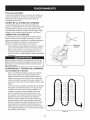
Suggested
•
•
•
Tilling
Patterns
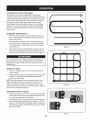
Whenpreparinga seedbed,go overthesame pathtwice inthe
first row,thenoverlapone-halfthe tillerwidth on the rest of the
passes.See Figure19.
Whenfinishedinone direction,makea secondpass at a right
angle,See Figure20. Overlapeachpass for thebest results(in
very hard ground,itmay take threeor four passesto thoroughly
pulverizethe soil.)
If thegarden sizewill not permitlengthwiseand then crosswise
tilling,then overlapthe firstpassesby one-halfa tillerwidth,followedby successivepassesat one-quarterwidth.See Figure21.
Figure19
[
Donot operatethe tilleron a slopetoo steepfor safeoperation.Till
slowlyand be sureyouhavegood footing.Neverpermitthe tiller to
freewheeldownslopes.Failureto followthis warningcouldresultin
personalinjury.
Tilling
1.
2.
m_m_
on a Slope
Till onlyon moderateslopes,neveron steep groundwherethe
footingisdifficult.
Tillingup and downslopes isrecommendedoverterracing.Tilling
verticallyon a slopeallowsmaximumplantingarea and also
leavesroomforcultivating.
NOTE:Whentilling on slopes,be surethe correctoil levelismaintainedinthe engine (checkeveryone-halfhour of operation).The
inclineof the slopewillcause the oil to slant awayfrom itsnormal
leveland this can starveengineparts of requiredlubrication.Keepthe
motoroil levelat thefull pointat all times.
t
Figure20
Tilling Up and Down a Slope
1. Tokeepsoil erosionto a minimum,be sureto add enoughorganic
matterto the soilso that it hasgood moistureholdingtextureand
try to avoidleavingfootprintsor wheelmarks.
2.
Whentillingvertically,try to makethe first pass uphillas the tiller
digs moredeeplygoing uphillthan it doesdownhill.In soft soilor
weeds,you may haveto lift the handlebarsslightlywhile goinguphill.Whengoing downhill,overlapthe first pass byaboutone-half
the widthof the tiller.
Figure21
16
j
f
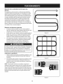
Terrace Gardening
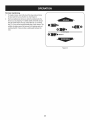
1. Tocreatea terrace,startat thetop of the slopeand work down
Go back and forth acrossthefirst row. See Figure22.
2.
Eachsucceedinglowerterraceis startedby walkingbelowthe
terraceyouare preparing.Foradded stabilityof the tiller,always
keepthe uphillwheelin the soft, newlytilledsoil. Donot till the
last 12"or moreof thedownhilloutside edgeof each terrace.This
untilledstrip helpspreventthe terracesfrombreakingapart and
washingdownhill.It also providesa walkingpath betweenthe
,O
rows,
' REPEA'
J
Figure22
17
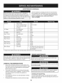
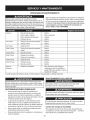
MAINTENANCE
SCHEDULE
Followthe maintenanceschedulegivenbelow.This chart describes
serviceguidelinesonly. Usethe ServiceLog columnto keeptrackof
completedmaintenancetasks.To locate the nearest Sears Service
Centeror to scheduleservice,simplycontactSears at
1-800-4-MY-HOME®.
Beforeperforminganytypeof maintenance/service,
disengageall
controlsand stoptheengine.Waituntilall movingpartshavecometo
a completestop.Disconnectsparkplugwireandgrounditagainstthe
enginetopreventunintendedstarting.Alwayswearsafetyglassesduring
operationor whileperforminganyadjustments
or repairs.
=
EachUse
.
2.
3.
Engineoil level
Looseor missinghardware
1.
Check
2.
3.
Tightenor_place
Clean
4.
Check
4.
Engineand aroundmuffler
Air cleaner
1.
Drivebelt tension
1.
Check
2.
Nutsand Bolts
2.
Check
1st5 hours
1.
Engineoil
1.
Change
Every10 hours
1.
Drivebelt tension
1.
Check
2.
1st2 hours
=
Unit
2.
Lubricate
Every25 hours
1.
Sparkplug
1.
Check
Every30 hours
1.
Tinesfor wear
1.
Check
2.
Tirepressure
2.
Check
Every50 hours
1.
Engineoill-
1.
Change
Every100hours
1.
Air cleaner
2.
SparkPlug
1.
2.
Change
Change
1.
Fuelsystem
1.
Runengineuntilit stopsfrom lackof
fuel or add a gasolineadditiveto the
gas in thetank.
BeforeStorage
Changeoil every twentyfive hourswhenoperatingengineunder heavyload or in high temperatures
ENGINE
MAINTENANCE
Alwaysstop engineand disconnectspark plug wirebeforeperforming
DO NOTcheckfor sparkwith spark plug removed.DO NOTcrank
enginewith sparkplug removed.
lany maintenanceor adjustments.Alwayswearsafetyglassesduring
[operationor while performingany adjustmentsor repairs.
GENERAL
RECOMMENDATIONS
•
Alwaysobserveall safety rulesfoundon productlabelsand in
this operator'smanualwhenperformingany maintenance.Safety
rulescan be foundon the productlabelsand in this Operator's
Manualbeginningon page3.
•
Thewarrantyon this tillerdoes notcover itemsthat havebeen
subjectedto operatorabuseor negligence.Toreceivefull value
fromwarranty,operatormust maintainthe equipmentas
instructedhere.
•
Someadjustmentswillhaveto be madeperiodicallyto maintain
yourunit properly.
•
Periodicallycheckall fastenersand makesuretheseare tight.
If the enginehas been running,the mufflerwill be very hot. Be careful
notto touch the muffler.
Thespark plug mustbe securelytightened.An improperlytightened
sparkplug can becomevery hot and may damagethe engine.
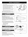
Checking
the Spark Plug
Toensureproperengineoperation,the spark plug mustbe properly
gappedand free of deposits.Checkthe spark plugevery 25 hoursand
replaceitevery 100 hours.
18
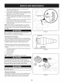
1.
2.
Removethespark plug bootand use a sparkplug wrenchto
removethe plug.See Figure23.
Visuallyinspectthe spark plug.Discardthe spark plug if thereis
apparentwear,or if the insulatoris crackedor chipped.Cleanthe
sparkplug with a wirebrush if it is to be reused.
3.
Measurethe plug gap with a feelergauge.Correctas necessary
by bendingsideelectrode.See Figure24.The gap shouldbe set
to 0.030in.
4.
Checkthatthe sparkplug washeris in good conditionand thread
the sparkplug in by handto preventcrossthreading.
5.
After thespark plug is seated,tightenwith a spark plugwrenchto
compressthe washer.
NOTE:Wheninstallinga newspark plug,tighten 1/2turn after the
sparkplug seatsto compressthe washer.Whenreinstallinga used
sparkplug,tighten 1/8-1/4turnafter the spark plug seatsto compress
the washer.
Figure23
Neverusegasolineor low flash pointsolventsfor cleaningthe air
c eanere ement.A f re or expos on cou d resut.
,Electrode
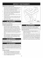
Servicing
the Air Cleaner
Theair cleanerpreventsdamagingdirt, dust,etc.,from enteringthe
carburetorand beingforced intothe engineand is importantto engine
life and performance.Neverrun the enginewithoutan air cleaner
completelyassembled.Checkthe air cleanerbeforeeach use.
Paperfilterscannotbe cleanedand mustbe replacedonce a year
or every 100operatinghours;moreoften if usedin extremelydusty
conditions.
1.
2.
3.
4.
0.02-0.03
in.
===_1_====0.60-0.80 rnrn
Pressthe tab on the air filter cover,lift the coverand removethe
air filter.See Figure25.
Discardold air filter.
Installnewair filter.
Closethe cover.
J
Figure24
NOTE:If the filter is torn or damagedin anyway,replaceit.
Donot sprayenginewith waterto clean becausewatercould
contaminatefuel. Usinga garden hoseor pressurewashingequipment canalso forcewater intothe muffleropening.Waterthat passes
throughthe mufflercanenterthe cylinder,causingdamage.
Air Filter
Cover
Filter
Accumulationof debrisaroundmufflercouldcause a fire. Inspectand
cleanbeforeevery use.
Cleaning
the Engine
If theengine hasbeen running,allowit to coolfor at least halfan hour
beforecleaning.Periodicallyremovedirt build-upfrom theengine.
Cleanaroundthe muffler.Cleanwith a brushor compressedair.
J
Figure25
19
Check Engine Oil
1. Checkoil beforeeachuse. Stopengineand wait severalminutes
beforecheckingoil level.With the tilleron levelground,the oil
mustbe to FULLmarkon dipstick.
2.
3.
Removeoil fill dipstickand wipe cleanwith cloth.
Replacedipstick intothe oil filler neck,but do not screwitin.
Removeand checkoil level. Levelshouldbe at FULLmark.
4.
5.
If needed,add oil slowly- recheck.Do not overfill.
Wipedipstickclean, replacebut do not tighten.Removeand
checkoil level.Oil levelshouldbe at FULLline on dipstick.
Replaceand tighten dipstickfirmlybeforestartingengine.
6.
DO NOTuse non-detergentoil or 2-strokeengineoil. It could shorten
the engine'sservicelife.
Change Engine Oil
•
SAE 10W-30is recommendedforgeneral,all temperatureuse.
Whenaddingoil to the engine,referto viscositychart inthe
operationsection.Usea 4-stroke,or an equivalenthigh detergent, premiumqualitymotoroil certifiedto meetor exceedU.S.
automobilemanufacturer'srequirementsfor serviceclassification
SG,SR MotoroilsclassifiedSG,SF will showthis designationon
thecontainer.
•
Changeengineoil after thefirst five to eight hoursof operation,
and everyfifty hoursor every seasonthereafter.Changeoil every
twentyfive hourswhenoperatingengineunder heavyload or in
high temperatures.
oil
Drain
Figure 26
4.
Replaceand tightenthe oil drain end cap.
5.
Whenengine isdrainedof all oil, placeenginelevel. Refillwith
approximately20 oz. of fresh oil. Fillto FULLline on dipstick.
Donot overfill.Referto CheckEngineOil inthis SERVICE&
MAINTENANCEsection.
6.
Replacespark plugwire beforestarting.
Beforetippingengineor equipmentto drainoil, drain fuel fromtank by
runningengineuntilfuel tank isempty.
Used motoroil maycause skincancer ifrepeatedlyleft in contactwith
the skin for prolongedperiods.Althoughthis isunlikelyunlessyou
handleusedoil on a daily basis,itis still advisableto thoroughlywash
yourhandswith soapand wateras soonas possibleafter handling
usedoil.
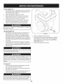
To Drain Oil
1.
Drainthe fuelfrom the tank by runningthe engineuntil thefuel
tank isempty.Be surefuel fill cap issecure.
2.
Withengine OFF butstill warm,disconnectspark plugwire and
keepitawayfrom spark plug.
Removeoil drain end cap locatedat the baseof the engine,and
drainoil into an appropriatereceptacle.See Figure26.
3.
Used oil isa hazardouswasteproduct.Disposeof usedoil properly
IDo not discardwith householdwaste.Checkwith yourlocalauthori_tiesor SearsServiceCenterfor safedisposal/recyclingfacilities.
2O
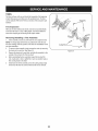
LUBRiCATiON
f
After every 10operatinghours,oil or greasethe lubricationpoints.Use
cleanlubricatingoil (#30 weightmotoroil is suitable)and cleangeneral
purposegrease(greasecontaininga metallubricantis preferred,if
available).
*
Removethetines and cleanthe fine shaft. Usea file or sandpaper to gently removeany rust,burrsor roughspots(especially
aroundthe holesin the shaft). Applygreaseto the endsof the
shaftbeforeinstalling
the tines.
,
*
J
Hex Stop
Nut
Removethebelt coverand lubricateall the pivot pointsand
linkageswith a lightcoat of oil. Keepthe beltsfree of lubrication.
Thechaincase is pre-lubricatedand sealedat the factoryand
requiresno maintenance.
HARDWARE
Checkfor looseor missinghardwareafter every 10operatinghours
and tightenor replace= as needed= beforereusingthe tiller.Be
sureto checkthe screwsunderneaththe tillerhood that securethe
transmissioncoverand the DepthRegulatorLeverto thetransmission.
Washer
Figure27
Beforeperformingany type of maintenanceon the machine,wait for
all partsto stop movingand disconnectthe spark plugwire. Failure
to followthis instruction
couldresult inpersonalinjuryor property
damage.
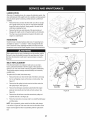
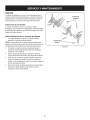
BELT REPLACEMENT
If thedrive beltneedsto be replaced,makesureyou useonly a
factoryauthorizedbelt listedin the Partspagesof this operator's
manual,as an "over-the-counter"beltmay not performsatisfactorily.
Theprocedurerequiresaveragemechanicalability and commonly
availabletools.
Toreplacethe Drivebelt,follow these steps:
1.
Removethebelt coverfrom the left side of the tillerby removing
the two self tappingscrewsand hex stop nutand washer.See
Figure27.
2.
Removetheidlerpulleybolt and movethe beltfrom underthe
Transmission
idlerpulleykeeper.See Figure28.
3.
Pulley
Removethebelt keeperassemblylocatedbehindtheengine
J
pulleyby removingthe two hexbolts and lock washers.See
Figure28
Figure28.
4.
Removetheold beltfrom aroundthe transmissionpulleyand
installthe new belt. See Figure28.
5.
Followthe instructionsin reverseorder to re-installthe beltkeeper
and idler pulley.
NOTE:Uponreassernbly,makecertain that the idlerpulleykeeper
isas shownin Figure28. Takenoteof the notchon the bottomof the
keeperand the alignmentwhenreassemblingwith the replacement
belt.
21
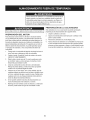
TINES
Thetines will wearwith useand shouldbe inspected
at the beginning
of eachtillingseasonand after every30 operatinghours.Thetines
can be replaced.Referto the PartsList sectionof this manualfor part
numbers.
Clevis Pin
Tine inspection
With use,the tines will becomeshorter,narrowerand pointed.Badly
worntines will resultina lossof tillingdepth,and reducedeffectivenesswhen choppingup and turningunderorganicmatter.
Removing/Installing
a Tine Assembly
1. A tine assemblyconsistsof a left hand fineand a righthandfine.
NOTE:Thesharpedgesof the tines are positionedto enterthe soil
firstwhen rotating.Notethis positionof the tines for reinstallationof the
newfine assemblies.
2.
3.
4.
5.
To removea fine assembly,simplyremovethe cotterpin securing
theclevis pin for eachfine. See Figure29.
Removethe clevispin foreachfine, and slidetheassemblyto the
outsideof the unitand off of the fine shaft.
Beforereinstallingthe fineassembly,inspectthe tine shaftfor
rust, roughspotsor burrs. Lightlyfile or sand,as needed.Applya
thincoat of greaseto the shaft.
Installeachtine of theassemblyso that thecutting(sharp)edge
of the tineswill enterthe soil firstwhenthe tiller movesforward.
22
J
Figure29
Neverstoretiller withfuel in tank indoorsor in poorlyventilatedareasI
wherefuel fumesmay reachan open flame,spark,or pilotlightas on
a furnace,water heater,c othesdryer, or gas app ance.
PREPARING
THE ENGINE
Enginesstored between30 and 90 days needto be treatedwith a
gasolinestabilizerand enginesstoredover90 days needto be drained
of fuel to preventdeteriorationand gumfrom formingin fuel systemor
on essentialcarburetorparts.If the gasolinein yourenginedeterioratesduringstorage,you mayneed to havethecarburetor,and other
fuel systemcomponents,servicedor replaced.
1. Removeall fuel from tank by runningengine untilit stopsfrom
lack of fuel.
2.
Changethe oil. See ChangeEngineOil in SERVICEAND
MAINTENANCE
section.
3.
Removespark plugand pourabouta 1/2ounceof engineoil into
the cylinder.Replacespark plug and crankit slowlyto distribute
oil.
4.
Cleandebrisfrom aroundtheengine and the muffler.Touchup
any damagedpaint,and coat otherareasthat may rustwith a light
film of oil.
5.
Storein a clean,dry and wellventilatedarea awayfromany appliancethat operateswith a flame or pilot light, suchas a furnace,
water heater,or clothesdryer.Alsoavoidany areawith a spark
producingelectricmotor,or wherepowertoolsare operated.
If possible,also avoidstorageareaswith high humidity,because
that promotesrust and corrosion.
6.
7.
THE TILLER
Whenthe tillerwon't be usedfor an extendedperiod,prepareit for
storageas follows:
1. Cleanthe tillerand engine.
Neverleaveengineunattendedwhileit is running.
PREPARING
1
Keeptheengine levelin storage.Tiltingcan causefuel or oil
leakage.
23
2.
Followthe lubricationrecommendations
and checkfor looseparts
and hardware.
3.
4.
Storethe tiller in a clean,dry area.
Neverstore the tillerwith fuel in the fuel tank in an enclosedarea
wheregas fumescould reachan open flameor spark,or where
ignitionsourcesare present(spaceheaters,hot waterheaters,
furnaces,etc.).
Beforeperforminganytype d maintenance/service,
disengageall controlsand stoptheengine.Waituntilall
movingpartshavecometo a completestop.Disconnectsparkplugwireandgroundit againsttheengineto prevent
unintendedstarting.Alwayswearsafetyglassesduringoperationor whileperforminganyadjustmentsor repairs.
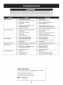
1.
Sparkplugwire disconnected.
1.
Reconnectwire.
2.
3.
4.
EngineThrottleControlLeverincorrectlyset.
Fueltank emptyor stale fuel.
Dirtyair filter.
2.
3.
4.
Putleverin STARTposition.
Filltank with clean,fresh gasoline.
Cleanor replacefilter.
5.
6.
7.
Defectiveor incorrectlygappedspark plug.
Misadjustedthrottlecontrol.
Dirt orwater in fuel tank.
5.
6.
Clean, adjustgap,or replace.
Contactyour SearsParts& RepairCenter.
7.
Contactyour SearsParts& RepairCenter.
1.
2.
3.
Defectiveor incorrectlygappedspark plug.
Dirtyair filter(s).
Carburetorout of adjustment.
1.
2.
3.
Clean, adjustgap,or replace.
Cleanor replace.
Contactyour SearsParts& RepairCenter.
4.
5.
Stalegasoline.
Dirt or water in fuel tank.
4.
5.
Replacewith fresh gasoline.
Contactyour SearsParts& RepairCenter.
6.
Enginecoolingsystemclogged.
6.
Cleanair coolingsystem.
1.
Enginecoolingsystemclogged.
1.
Cleanair coolingarea.
2.
3.
Carburetorout of adjustment.
Oil levelis low.
2.
3.
Contactyour SearsParts& RepairCenter.
Checkoil level.
Enginedoesnot shut off
1.
Misadjustedthrottlecontrolor ignitionswitch. 1.
Contactyour SearsParts& RepairCenter.
Tineswill notturn
1.
2.
Improperuse of controls.
Worn,broken,or misadjusteddrive belt.
1.
2.
ReviewOperationsection.
Replaceor adjustbelt.
3.
4.
Foreignobjectlodged in tines.
Tineclevispin(s) missing.
3.
4.
Dislodgeforeignobject.
Replacetineclevispin(s).
1.
Worntines.
2.
Incorrectthrottlesetting.
3.
DriveBelt slipping.
1.
1.
1.
ReplaceTines.
See Service& MaintenanceSection.
See Service& MaintenanceSection.
Enginefails to start
Enginerunserratically
Engineoverheats
Poortilling performance
NEED MORE HELP?
Youq.] [_}d the a_swe_
a_d. mo_e on ma_agemy_i_eo_em
Find this and all your other product manuals online.
Get answers
from
our team
of home experts,
Get a personalized maintenance plan for your home.
Find information
and tools to help with home projects,
÷managemylife
24
- ff}[ f_'ee!
25
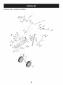
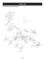
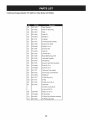
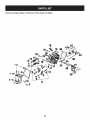
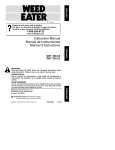
Craftsman
Tiller B IViodel No. 247.29934
22
12
21
14
32
1
26
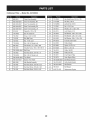
Craftsman
Tiller B IViodel No. 247.29934
720-0274
Grip,Handle
2
686-0081A-0637 WheelBracketAssembly
911-0415
ClevisPin, .375x 1.75
22
731-06253A
HandleCover
3
714-04043
BowTie Cotter Pin
23
931-1645B
ClutchBail Holder
4
734-04547
CompleteWheelAssy.8 x 1.75
24
936-0140
Fiat Washer,.385x .62 x .063
5
738-0929
ShoulderScrew,.496x 1.4453/8-16
25
736-0242
Bell Washer,.340x .872x .060
6
710-0805
HexHeadScrew,5/16-18x 1.50
26
936-0921
Lock Washer,1/2
7
712-04063
Nut,5/16-18,FlangeLock
27
936-3020
Flat Washer,.271x .630x .065
8
750-0890
Spacer,.325ID x .75OD x .520
28
749-1401A-4044 HandleBrace
9
786-0003-0637
Tail Bracket,LH
29
710-0176
Hex HeadScrew,5/16-18x 2.75
10
786-0004-0637
Tail Bracket,RH
30
710-0502A
SEMSScrew,3/8-16
11
786-0005-0637
DepthBar
31
710-0602
Self-TappingScrew,5/16-18x 1.00
12
649-04040-4044 CompleteHandleAssembly
32
710-0604A
Self-TappingScrew,5/16-18x .625
13
686-0083-0637
ClutchBail
33
912-0240
Jam Nut,7/16-20
14
710-0641
HexHeadScrew,1/4-20x 2.25
34
912-0429
Nylon HexLock Nut,5/16-18
15
710-1236
CarriageScrew,5/16-18x 1.00
35
936-0171
Lock Washer,7/16
738-0934
ShoulderScrew,.475x 2.115/16-18
Spacer,.47OD x .96
16
710-3194
HexHeadScrew,1/2-20x .750
36
17
912-0298
Jam Nut, 1/4-20
37
750-0470
18
912-0442
Nut,1/4-20,Lock
38
786-0138A-4044 Frame,RH
19
720-0195
HandleKnob
39
786-0139A-4044 Frame,LH
20
720-0269
Grip,ClutchBail
40
786-0145A-4044 EngineMountingPlate
27
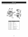
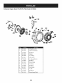
Craftsman
Tiller B Model No. 247.29934
\\
17
i_
34
33
35
37
27
_26
10
28
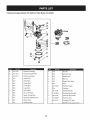
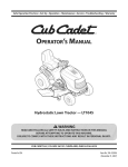
Craftsman
Tiller B IViodel No. 247.29934
710-3005
Hex HeadScrew,3/8-16x 1.25
711-1036A
Hex Nut,5/16-18
986-0091
ChainCaseAssembly
2
642-0002-0637
inner TineAssembly,RH
24
3
642-0003-0637
inner TineAssembly,LH
25
,7120266A
4
642-0004-0637
OuterTineAssembly,RH
26
712-3029
Nut,1/2-20,Jam
5
642-0005-0637
OuterTineAssembly,LH
27
736-0112
Washer,.531x 1.62x .045
6
911-0415
ClevisPin,.375x 1.75
28
936-0119
LockWasher,5/16
7
714-04043
BowTie CotterPin
29
736-0242
Bell Washer,.340x .872x .060
8
710-0599
Screw,1/4-20x 0.500
30
736-0312
FiatWasher,1.26x 1.87x .150
9
711-0919
Bolt, Belt Cover
31
936-0452
Bell Washer,.396x 1.140x .095
10
712-0392
Nut, 1/4-28,Lock
32
946-0918
ForwardClutchCable
11
712-3004A
Nut,5/16-18,FlangeLock
33
948-0350
PulleyAdaptor
12
936-3020
Fiat Washer,.271x .630x .065
34
950-0892
Spacer,.64 ID x 2.4
13
738-0930
ShoulderScrew,.560x .1655/16-18
35
954-0428
Belt,4L x 41.9LG
14
786-0056A-4044 Belt Cover
36
756-0313
Pulley1.88OD
15
710-3008
Hex HeadScrew,5/16-18x .75
37
756-0585
Pulley6.00OD
16
712-04063
Nut,5/16-18,FlangeLock
38
756-0971
InnerEnginePulley
17
786-0043A-4044 TineShield
39
756-0972
Outer EnginePulley
18
786-0053-0637
Bracket,Tine Shield
40
786-0039B-0637 BeltKeeperBracket
19
686-0088
Idler BracketAssembly
41
786-0129-0637
CableGuide Bracket
20
710-0189
Hex HeadScrew,5/16-18x 3.00
42
786-0144-0637
IdlerBracket
21
710-0237
Hex HeadScrew,5/16-24x .625
43
786-0149
BeltKeeper
22
710-1039
Hex HeadScrew,3/8-24x 1.00
44
952Z170-VOB
ReplacementEngine
29
. Jamlock Nut,3/8-16
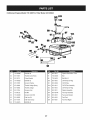
Craftsman
Engine
IViodel 170=VOB For Tiller IViodel 247.29934
17
2O
31
m
D =
O
0
20
951-11285
ExhaustPipe Gasket
21
712-04214
Nut,M8
22
751-12294
MufflerAssembly
23
710-05002
Bolt
30
951-10806
Air CleanerHousing
31
712-04213
Nut
32
710-05102
Self-TappingBolt M4.2x16
34
951-12135
SilencerPlate
35
951-10794
Air CleanerAssembly
36
951-10794
Air CleanerAssembly
37
951-12136
Air CleanerCover
3O
Craftsman
Engine
IViodel 170-VOB For Tiller IViodel 247.29934
29
m
D =
I!
m
q!
28
951-10797
CarburetorAssembly
29
951-11571
CarburetorGasketPlate
a
951-11177
ControlLever,Choke
b
N/A
ChokeShaft
C
N/A
ChokePlate
d
N/A
e
f
D =
I!
O
I11
N/A
FloatPin
n
N/A
EmulsionTube
0
N/A
NeedleValve
P
N/A
MainJet
q
N/A
NeedleValveSpring
ThrottleShaft
r
N/A
Float
N/A
ThrottlePlate
s
951-11589
FuelBowlGasket
N/A
ScrewM3x5
t
N/A
FuelBowl
g
N/A
LockWasher
U
951-11348
FuelBowlGasket
h
N/A
IdleJet Assembly
V
710-04945
FuelBowlMountingBolt
I
N/A
Gasket,ThrottlePlate
W
951-11349
FuelDrainPlugGasket
J
N/A
IdleSpeedAdjustingScrew
X
710-04938
FuelDrainPlug
k
N/A
MixtureScrew
951-12119
CarburetorKit- Major
I
N/A
CarburetorBody
(Incl Ref.I,m,n,o,p,q,r,s,u
& w)
31
Craftsman
Engine
IViodel 170=VOB For Tiller IViodel 247.29934
|56
32
Craftsman
Engine
IViodel 170=VOB For Tiller IViodel 247.29934
m
D =
B
44
951-11253
PistonRingSet
45
951-11632
PistonPin Snap Ring
46
951-12007
Piston
47
951-11633
PistonPin
48
710-04915
Bolt M6x12
49
951-11113
Air Shield
5O
951-11573
ConnectingRodAssembly
51
951-11356
GovernorArm Shaft
52
736-04461
Washer5.2xl.9
53
951-11574
GovernorSeal
54
714-04074
CotterPin
55
951-11575
CamshaftAssy.
56
951-11369
RadialBall Bearing,6205
57
951-12160
CrankshaftAssembly
58
951-10307
WoodruffKey
59
951-11576
GovernorGear/ShaftAssembly
6O
715-04092
DowelPin 7x14
61
715-04089
DowelPin 9x14
62
951-11371
CrankcaseCoverGasket
63
951-12125
CoverComp,Left Crankcase
64
710-04932
Bolt M8x32
65
951-11377
Oil FillerPlugAss'y
65a
951-11577
O-Ring
66
951-11578
Oil Seal,25x41.25x6
67
951-12155
Short Block
(Incl Ref.4,20,25,26,38,
40,41,44-47,50-70)
68
736-04440
Washer10x16x1.5
69
710-04906
Oil DrainPlug
112
951-10370
Oil DrainPlug& WasherAssembly
113
951-11283
Oil FillPlug Assembly
33
Craftsman
Engine
Model 170=VOB For Tiller Model 247.29934
42
40
1
1
11
1
I
5
34
Craftsman
Engine
IViodel 170=VOB For Tiller IViodel 247.29934
m
D =
B
m
0
D =
O
1
710-04968
BoltM6x16
19
710-05276
MufflerStud M8x36
2
951-11054
ValveCover
19
951-10657
MufflerStudAssembly
3
731-07059
BreatherHose
24
710-05101
StudM6x110
951-11567
CarburetorInsulatorGasket
3a
726-04101
HoseClamp
25
4
951-11565
ValveCoverGasket
26
951-11568
CarburetorInsulator
5
951-11892
RockerArmAssembly
27
951-11569
CarburetorGasket
6
751-11124
Nut,Pivot Locking
38
951-11572
Gasket,CylinderHead
AdjustingNut ,Valve
39
951-10648
PushRod
RockerArm
4O
951-11899
Tappet
715-04090
DowelPin 10x16
7
751-11123
8
951-11893
9
710-04902
Bolt, Pivot
41
10
951-11895
PushRodGuide
42
951-10647A
ValveKit
11
951-12000
Retainer,In.ValveSpring
43
951-10647A
ValveKit
12
951-12002
Adjuster,ExhValve
114
951-11063A
ValveCoverKit
13
951-12003
Retainer,Ex.ValveSpring
951-10819
CylinderHeadService Kit
14
951-12004
ValveSpring
15
951-11894
IntakeValveSeal
16
710-04933
BoltM8x55
17
951-10668A
CylinderHeadAssembly
18
951-10292
(Incl Ref.4,15,16& 38)
951-12120
GasketKit, External
(Incl Ref.4,20,25,26,27,29
& 68)
951-12121
GasketKit, Complete
(Incl Ref.4,6-15,17,20,
(Incl Ref.4,20,25,26,27,29,38,52,
25,26,38,42& 43)
53,62,66,68& 70)
SparkPlug/F6Rtc
35
Craftsman
Engine
IViodel 170=VOB For Tiller IViodel 247.29934
75
72
7g
78
73
74
8O
m
D =
O
O
7O
951-12126
Oil Seal25x41.25x6
71
951-10792
IgnitionCoil Assembly
72
710-04919
BoltM6x25
73
951-10805
Flywheel
74
951-10909
Fan,Cooling
75
951-10911
Pulley,Starter
76
712-04209
Nut,Special,M14x1.5
77
710-04915
BoltM6x12
79
951-11583
BlowerHousing
80
736-04455
FlatWasher
81
710-04974
BoltM6xlO
82
951-12127
RecoilStarter
109
712-04212
Nut,M6
110
710-04918
BoltM6x20
111
951-11109
BlowerHousingShield
36
Craftsman
Engine
IViodel 170=VOB For Tiller IViodel 247.29934
O3
O2
107
m
D =
m
O
D =
O
O
1
710-04968
BoltM6x16
96
951-11914
DipstickDecorationCover
83
951-11067
ThrottleControlKnob
97
710-04905
Bolt
84
951-12131
PrimerBracket
98
710-04915
Bolt M6x12
85
710-04928
BoltM6x12
1CO 951-11903
Oil FillTubeO-Ring
86
951-11585
GovernorSpring
101
Oil FillTube
87
951-10664
ThrottleLinkageSpring
101a 951-11913
Oil FillTubeAssembly
88
951-10665
ThrottleLinkage
102
951-11904
Oil FillTubeO-Ring
9O
951-11106
GovernorArm
103
951-11912
DipstickAssembly
91
712-04212
Nut M6
104
951-10917A
FuelCapAssembly
92
710-04908
GovernorArmBolt
106
951-11933
FuelLevelIndicator
93
951-10650
FuelLine Kit
107
951-12159
FuelTank
94
951-11700
FuelHoseClamp
108
951-10651
FuelTankNipple
95
710-04915
BoltM6x12
37
951-10656
Craftsman Tiller
IViodel No. 247.29934
777D15526
777123259
777i23174
777S33498
777D15527
777D15447
777D15452
777S33612
777120358
777122502
38
(Thispage applicablein the U.S.A.and Canadaonly.)
Sears Brands Management Corporation (Sears), the California Air Resources Board (CARD)
and the United States Environmental
Protection Agency (U.S. EPA)
Emission Control System Warranty Statement (Owner's Defect Warranty Rights and Obligations)
EMISSIONCONTROLWARRANTYCOVERAGEISAPPLICABLETO CERTIFIEDENGINESPURCHASEDIN CALIFORNIAIN 1995ANDTHEREAFTER,WHICHARE USEDINCALIFORNIA,ANDTO CERTIFIEDMODEL
California
and United
States
YEAR 1997AND LATERENGINESWHICHARE PURCHASEDAND USED
ELSEWHEREIN THE UNITEDSTATES(ANDAFTERJANUARY1,2001 IN
CANADA).
Emission
Control
The CaliforniaAir ResourcesBoard(CARD),U.S.EPAand Searsare pleased
to explainthe EmissionControlSystemWarrantyon your modelyear2000and
latersmalloff-roadengine(SORE).In California,newsmall off-roadengines
mustbe designed,builtand equippedto meetthe State'sstringentanti-smog
standards.Elsewherein the UnitedStates, newnon-road,spark-ignition
enginescertifiedfor modelyear 1997and latermustmeetsimilar standardsset
forth bythe U.S.EPA.Sears mustwarrantthe emissioncontrol systemon your
Sears Emission
Control
Statement
parton yourengineis defective,the part will be repairedor replacedbySears.
Warranty
Responsibilities
Asthe smalloff-roadengine owner,you are responsiblefor the performanceof
the requiredmaintenancelistedin yourOperatingand MaintenanceInstructions.Searsrecommendsthatyou retain all yourreceiptscoveringmaintenance
on yoursmalloff-roadengine,but Sears cannotdenywarrantysolelyfor the
lackof receiptsor for yourfailureto ensurethe performanceof all scheduled
maintenance.As the smalloff-roadengineowner,you shouldhoweverbe
awarethat Searsmay denyyou warrantycoverageif your smalloff-roadengine
or a part hasfailed dueto abuse,neglect,impropermaintenanceor unap-
Sears Emission
Warranty
Defects Warranty Coverage
Smalloff-roadenginesarewarrantedrelativeto emissioncontrol partsdefects
fora periodof one year,subjectto provisionsset forth below.Ifany covered
Owner's
Defects
enginefor the periodsoftime listedbelow,providedtherehas been noabuse,
neglector impropermaintenanceof your smalloff-roadengine.Youremission controlsystemincludespartssuch as the carburetor,air cleaner,ignition
system,mufflerand catalyticconverter.Also includedmay be connectorsand
otheremissionrelatedassemblies.Wherea warrantableconditionexists,Sears
will repairyour smalloff-roadengineat no costto you includingdiagnosis,parts
and labor.
provedmodifications.You
are responsiblefor presentingyour smalloff-road
engineto an AuthorizedSearsServiceDealeras soonas a problemexists.The
undisputedwarrantyrepairsshouldbe completedina reasonableamountof
time,not to exceed30 days. Ifyou haveany questionsregardingyourwarranty
rightsand responsibilities,you shouldcontacta SearsService Representative
at 1-800-469-4663.
The emissionwarrantyis a defectswarranty.Defectsare
judged on normalengineperformance.Thewarrantyis not relatedto an in-use
emissiontest.
Control Defects Warranty Provisions
Thefollowingarespecificprovisions
relativetoyourEmission
ControlDefectsWarranty
Coverage.
Itisin addition
totheSearsenginewarranty
fornon-regulated
enginesfound in the Operatingand MaintenanceInstructions.
1. WarrantedParts
3. NoCharge
Repairor replacementof anyWarrantedPartwill be performedat no
chargeto the owner,includingdiagnosticlabor whichleads to the
determinationthata WarrantedPartis defective,if the diagnosticwork is
performedat an AuthorizedSears ServiceDealer.For emissionswarranty
servicecontact yournearestAuthorizedSears ServiceDealeras listed in
the "YellowPages"under"Engines,Gasoline,""GasolineEngines,""Lawn
Mowers,"or similar category.
4. Claimsand CoverageExclusions
Warrantyclaimsshall be filed in accordancewiththe provisionsof the
Sears EngineWarrantyPolicy.Warrantycoverageshall be excludedfor
failuresof WarrantedPartswhichare not original Sears partsor because
of abuse, neglector impropermaintenanceas setforth inthe Sears
EngineWarrantyPolicy.Sears is not liableto coverfailuresof Warranted
Partscausedby the use of add-on, non-original,or modifiedparts.
5. Maintenance
Coverageunderthis warrantyextendsonly to the parts listedbelow (the
emissioncontrolsystemsparts)to the extentthese partswere presenton
the engine purchased.
a. FuelMeteringSystem
• Cold start enrichmentsystem
• Carburetorand internalparts
• FuelPump
b. Air lnduction System
• Air cleaner
• Intakemanifold
c. IgnitionSystem
• Spark plug(s)
• Magnetoignitionsystem
d. CatalystSystem
• Catalyticconverter
• Exhaustmanifold
Any WarrantedPart whichis not scheduledfor replacementas required
maintenanceor whichis scheduledonly for regularinspectionto the effect
of "repairor replaceas necessary"shallbe warrantedasto defectsfor the
warrantyperiod.Any WarrantedPartwhich is scheduledfor replacement
as requiredmaintenanceshallbe warrantedasto defectsonly forthe
periodof time up to the first scheduledreplacementfor that part. Any
replacementpart that is equivalentin performanceand durabilitymay
be usedin the performanceof any maintenanceor repairs.The owneris
responsibleforthe performanceof all requiredmaintenance,as definedin
the SearsOperatingand MaintenanceInstructions.
6. ConsequentialCoverage
Coveragehereundershallextend to the failure of any engine components
caused bythe failureof any WarrantedPartstill underwarranty.
• Air injectionsystemor pulsevalve
e. MiscellaneousItemsUsedin AboveSystems
• Vacuum,temperature,position,time sensitivevalves
andswitches
• Connectorsandassemblies
2. Lengthof Coverage
Searswarrantsto the initialownerand eachsubsequentpurchaserthat
the WarrantedParts shallbe free from defects in materialsandworkmanshipwhich causedthe failure of the WarrantedPartsfor a periodof one
yearfrom the datethe engineis deliveredto a retailpurchaser.
Inthe USAandCanada,a 24 hour hot line, 1-800-469-4663,has a menu of pre-recordedmessagesofferingyou enginemaintenanceinformation.
GD0C-100188Rev.B
55
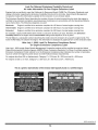
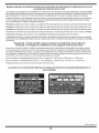
Look For Relevant Emissions Durability Period and
Air index information On Your Engine Emissions Label
Engines that are certified to meet the California Air Resources Board (CARB) Tier 2 Emission Standards must
display information regarding the Emissions Durability Period and the Air Index. Sears Brands Management
Corporation makes this information available to the consumer on our emission labels.
The Emissions Durability Period describes the number of hours of actual running time for which the engine is
certified to be emissions compliant, assuming proper maintenance in accordance with the Operating & Maintenance Instructions. The following categories are used:
Moderate:
Engine is certified
to be emission compliant
for 125 hours of actual engine running time.
Intermediate:
Engine is certified
to be emission compliant
for 250 hours of actual engine running time.
Extended:
Engine is certified
to be emission compliant
for 500 hours of actual engine running time.
For example, a typical walk-behind lawn mower is used 20 to 25 hours per year. Therefore, the Emissions
Durability Period of an engine with an intermediate rating would equate to 10 to 12 years.
The Air index is a calculated number describing the relative level of emissions for a specific engine family. The
lower the Air Index, the cleaner the engine. This information is displayed in graphical form on the emissions label.
After
July 1,2000, Look For Emissions
Compliance
On Engine Emissions
Compliance
Label
Period
After July 1, 2000 certain Sears Brands Management Corporation engines will be certified to meet the United
States Environmental Protection Agency (USEPA) Phase 2 emission standards. For Phase 2 certified engines, the
Emissions Compliance Period referred to on the Emissions Compliance label indicates the number of operating
hours for which the engine has been shown to meet Federal emission requirements.
For engines less than 225 cc displacement,
For engines of 225 cc or more, Category
Category
C = 125 hours, B = 250 hours and A = 500 hours.
C = 250 hours, B = 500 hours and A = 1000 hours.
This is a generic representation of the emission label typically found on a certified engine.
FAMILY YBSXS.3192VA
274812
GDOC-100182
Rev.B
54
Congratulationson makinga smartpurchase.YournewCraftsman@
productis designedand manufacturedfor yearsof dependableoperation. But likeall products,it may requirerepairfrom time to time.That's
whenhavinga RepairProtectionAgreementcansave youmoneyand
aggravation.
Here'swhat the RepairProtectionAgreement*includes:
* Expert service byour 10,000professionalrepairspecialists
o Unlimitedserviceand no chargefor partsand laboron all
coveredrepairs
o Product replacementup to $1500if yourcoveredproductcan't be
fixed
• Discountof 10%from regularprice of serviceand relatedinstalled
parts notcoveredby theagreement;also, 10%off regularpriceof
preventivemaintenancecheck
• Fast help by phone- we call it RapidResolution- phone support
from a Searsrepresentative.Thinkof usas a "talkingowner's
manual."
58
Onceyou purchasethe Agreement,a simplephonecall is all that it
takesfor youto scheduleservice.Youcan call anytimedayor night,or
schedulea serviceappointmentonline.
The RepairProtectionAgreementis a risk-freepurchase.If youcancel
for any reasonduringthe productwarrantyperiod,wewill providea full
refund.Or,a proratedrefundanytimeafter the productwarrantyperiod
expires.Purchaseyour RepairProtectionAgreementtoday!
Somelimitationsand exclusionsapply. For pricesand additional
informationin the U.S.A. call 1-800-827-6655.
*Coverage in Canadavaries on some items. Forfull details call
Sears Canadaat 1-800-361-6665.
Sears Installation Service
ForSearsprofessionalinstallationof homeappliances,garagedoor
openers,waterheaters,and othermajorhomeitems,in the U.S.A.or
Canadacall 1-800-4-MY-HOME®.
Declaraci6n de garantia ...............
Medidas importantes de seguridad..
Armado ........................
Funcionamiento .................
Servicio y Mantenimiento ..........
Pagina 42
Paginas 43-46
Paginas 47-49
Paginas 50-56
Paginas 57-61
CRAFTSMAN
Almacenamiento fuera de temporada .... Pagina 62
Soluci6n de problemas ................
Pagina 63
Acuerdo de protecci6n para reparaciones. Pagina 66
NOmero de servicio ............
Cubierta posterior
DE DOS AI_IOS DE GARANTiA
PORDOSANOSa partir de la fechade cornpra,este productoest_garantizadocontracualquierdefectode materialo rnanode obra.El
productodefectuosorecibir_la reparaci6no la sustituci6ngratuitasi la reparaci6nno est_ disponible.
Para detalles sobre la garantia de cobertura
craftsman.corn
Esta garantia
NO incluye:
cubre los defectos
para obtener
SOLO de rnateriales
la reparaci6n
y fabricaci6n.
o reernplazo,
Cobertura
visite el sitio web: www.
de la garantia
•
•
Elernentosreutilizablesque puedengastarsepor el uso normaldentrodel periodode garanfia,tales corno
cuchillas,dientes,o cinturones.
•
•
ProductodaSosresultantesde los intentosdel usuariode rnodificaci6ndel producto,reparaci6no causadospor accesoriosde productos.
Reparadonesnecesariasdebidoal accidenteo por no operaro rnantenerel productosegQnlas instruccionesprovistas.
•
El rnantenirnientopreventivoo reparacionesnecesariasdebidoa una rnezclaincorrectade combustible,combustiblecontarninadoo
pasado.
Estagarantiaes inv_.lidasi este productose utilizaal rnisrnotiernpola prestaci6nde servicioscornercialeso si sealquila a otra persona.
Estagaranfiale otorgaderechoslegalesespedficos,y usted tarnbi_npuedetenerotrosderechosque variande estadoa estado.
Sears Brands
Management
Seriedel motor:
208cc
Tipode aceite del motor:
Capacidadde aceitedel motor:
10W30
20 onzas
Combustible:
Bujia:
Gasolinasin plorno
F6RTC
Separaci6nde las bujias:
.030"
© Sears Brands,LLC
Corporation,
Hoffman
Estates,
IL 60179
NSmero de rnodelo ..........................................................
NSmero de serie ..............................................................
Fechade compra .............................................................
Registreel nQrnerode rnodelo,nQrnerode serie
y fechade cornprarn_sarriba
42
Esta
m&quina
est&
diseSada
para
serutilizada
respetando
lasnormas
deseguridad
contenidas
eneste
manual.
AIigual
queconcualquier
tipo
deequipo
motorizado,
undescuido
oerror
porparte
deloperador
puede
producir
lesiones
graves.
Esta
m_quina
escapaz
deamputar
dedos,
manos
ypies
ydearrojar
residuos.
Denorespetar
lasinstrucciones
de
seguridad
siguientes
sepueden
producir
lesiones
graves
olamuerte.
Lapresencia
deeste
simbolo
indica
que
setrata
deinstrucciones
de
seguridad
importantes
que
sedeben
respetar
para
evitar
poner
enpeligro
suseguridad
personal
y/omaterial
yladeotras
personas.
Lea
ycumpla
todas
lasinstrucciones
deeste
manual
antes
deintentar
operar
esta
m&quina.
Sinorespeta
estas
instrucciones
puede
provocar
lesiones
personales.
Cuando
veaestesimbolo,
ipreste
atenci6n
alaadvertencia!
PROPOSICION 55 DE CALIFORNIA
Su responsabilidad--Lirnite el usode esta rn_.quinarnotorizada
alas personasque lean,cornprendany curnplanlas advertenciase
instruccionesque aparecenen este manualyen la rn_.quina.
El escapedel motorde este producto,algunosde suscomponentesy
algunos componentesdel vehiculocontieneno liberansustanciasquimicas
que el estadode Californiaconsideraque puedenproducirc_ncer,
defectosde nacimientouotros problemasreproductivos.Los homes de la
bateriay los accesoriosalines contienenplomoy compuestosde plomo,
sustanciasquimicasquesegQnIo establecidopor el Estadode California
causan c&ncery daSosen el sistemareproductivo.L&veselas manos
despuesde estar en contactocon estos componentes.
i6UARDEESTAS
INSTRUCCIONES!
CAPACITACION
PR E PA RATIVO S
•
Lea,cornprenday respetetodas las instruccionesque figuranen
la rn_.quina
yen el o los rnanualesantesde procedera arrnarlay
hacerlafuncionar.Guardeeste manualen un lugar seguropara
consultasfuturasy peri6dicas,asi cornopara solicitarrepuestos.
•
Reviserninuciosarnente
el &readonde se va a usarel equipo.
Retiretodaslas piedras,botellas,latasy otrosobjetosextra_os
que puedanser levantadoso arrojadoscausandolesiones
personaleso da_osa la rn_.quina.
•
Lea el manualdel operadory sigatodas las advertenciase
instruccionesde seguridad.Deno hacerlo,puedeocasionar
heridasde gravedadal operadory/o a los observadores.Ante
cualquierduda,Ilarneal 1-800-4MY-HOME.
Farniliarfcesecontodos los controlesy su correcto
funcionarniento.Sepac6rnodetenerla rn_.quina
y c6rno
desconectarloscontrolesr_.pidarnente.
No perrnitanuncaque los ni_osrnenoresde 14a_osutilicen
esta rn_.quina.Los ni_osde 14a_osen adelantedeben leer y
entenderlas instruccionesde operaci6ny norrnasde seguridad
contenidasen este manualyen la rn_.quinay deben ser
entrenadosy supervisadospor un adulto.
•
Paraprotegerselosojos, utilice siernpregalas o anteojosde
seguridadrnientrasopera la rn_.quinao rnientrasla ajusta o
repara.Losobjetosarrojadosque rebotanpuedenproducir
lesionesocularesgraves.
Utilicezapatosde trabajoresistentes,de suelafuerte,y
pantalonesy carnisasajustados.Las prendassueltasy las
alhajasse puedenengancharen laspiezas rn6viles.Nuncaopere
esta rn_.quinaestandodescalzoo consandalias.
Antes de encenderla rn_quinacontroleque todos los pernosy
tornillosest_n bienajustadospara garantizarque la rn_.quinase
encuentraen condicionessegurasde operaci6n.Adern_.s,realice
una inspecci6nvisualde la rn_.quina
a intervalosfrecuentespara
controlarsi la rnisrnaest,. da_ada.
•
•
•
•
•
•
•
Nuncaperrnitaque los adultosoperenesta rn_.quinasin recibir
antesla instrucci6napropiada.
Mantengaa losobservadores,rnascotasy ni_osal rnenosa 25
metrosde la rn_.quina
rnientrasest,. en funcionarniento.Detenga
la rn_.quinasi alguiense acerca.
•
Antes de arrancarel motor,desenganchelas palancasdel
ernbraguey despl_.celas(en casode haber)a la posici6nneutral
("N").
Nuncaenciendael motoren espacioscerradoso en unazona
con pocaventilaci6n.El escapedel motorcontienernon6xidode
carbono,un gas inodoroy letal.
•
Nuncadeje larn_.quinaen funcionarnientosin vigilancia.
•
Nuncaintenterealizarajustesrnientrasel motorest,. en rnarcha,
exceptoen los casosespecificarnenterecornendadosen el
manualdel operador.
Mantengao reernplacelas etiquetasde seguridade instrucciones
segQnsea necesario.
•
43
•
Manejo seguro de la gasolina:
Para evitarlesionespersonalesy da_os materialestenga muchocuidado al
manipularla gasolina.La gasolinaes sumamenteinflamabley sus vapores
puedencausarexplosiones.Si se derramagasolinaencimao sobre la ropa
se puedelesionargravementeya quese puedeincendiar. Lavesela piely
c_mbiesede ropade inmediato.
•
Utilices61olos recipientesparagasolinaautorizados.
•
Nunca Ilenelosrecipientesen el interiorde un veh[culoo cami6no
caja de remolquecon un recubrimientopl&stico.Coloquesiemprelos
recipientesen el pisoy lejos delveh[culoantesde Ilenarlos.
•
Cuandosea factible,retireel equipo a gasolinadel cami6no remolquey
Ileneloen el suelo.Si esto no es posible,Ileneelequipo en un remolque
con contenedorport_til,en vez de desde una boquilladispensadorade
gasolina.
•
Mantengala boquillaen contactocon el hordedel tanquede
combustibleo de laabertura del recipienteen todo momento,hasta
terminarde cargar.No utiliceun dispositivopara abrir/cerrar la boquilla.
•
Apaguetodos los cigarrillos,cigarros,pipas y otras fuentesde
combusti6n.
•
•
•
•
•
•
•
•
•
Nunca carguecombustibleen lam&quinaen un espaciocerrado.
Nunca saquela tapa de la gasolinani agreguecombustiblemientrasel
motorest&calienteo en marcha.Permitaque el motorse enfr[epot Io
menosdos minutosantesde volvera cargar combustible.
Nunca llene en excesoeltanquede combustible.Lleneel tanqueno
m&sde Y2pulgadapordebajo de la basedel cuello del tap6n de carga,
para dejar espaciopara laexpansi6ndel combustible.
Vuelvaa colocar la tapadel combustibley ajL]stelabien.
Limpiela gasolinaquese puedahaberderramadosobre el motoro el
equipo.Trasladela m_quinaa otra zona. Espere5 minutosantesde
encenderel motor.
•
Para reducirel riesgode incendio,mantengala m&quinalimpiade
pasto,hojas y de acumulaci6nde otrosescombros.Limpielosderrames
de aceiteo combustibley saquetodos los escombrosembebidosde
combustible.
•
Nunca guardela m_quinao el recipientede combustibleen un espacio
cerradodondehayafuego,chispas o luz piloto,como por ejemplode
calentadoresde agua, calefactoresde ambientes,hornos,secadoresde
ropa u otros aparatosa gas.
•
•
•
•
•
•
MANTENINIIENTO
FUNCIONANIIENTO
•
•
•
•
•
•
•
•
•
•
Si golpea algOnun objeto extraSoo si la m&quinacomienzaa emitir
un sonidopococomOno a vibrar,apagueel motorde inmediato.
Desconecteel cable de la buj[a,p6ngalohaciendomasacontrael motor
y siga los pasossiguientes:
a.
Inspeccionela m&quinaparaver si est_ daSada.
b.
Repareo reemplacelas piezasdaSadas.
c. Controlesi hay piezas flojasy ajQstelaspara asegurarque la
m&quinafuncionede maneraseguray continua.
Desenganchetodas las palancasde embrague(si las hay)y detengael
motorantes de dejar la posici6nde operaci6n(detr&sde las manijas).
Esperehasta quelosdientes se detengancompletamenteantesde
limpiarlos,hacer algQnajusteo inspeccionarlos.
Nunca enciendael motoren espacioscerradoso en unazonacon poca
ventilaci6n.El escape del motorcontienemon6xidode carbono, un gas
inodoroy letal.
El silenciadory el motorse calientany puedencausar quemaduras.No
los toque.
Tengaprecauci6ncuandolabreterrenocerca de vallas,edificiosy
servicios subterr_neos.Los dientesrotatoriospuedencausar daSos
materialeso lesionespersonales.
No sobrecarguela capacidadde la m_quinaintentandolabrarel suelo a
un niveldemasiadoprofundoo a unavelocidaddemasiador@ida.
Si la m&quinaarranca haciendoun sonidoo unavibraci6nrata, detenga
el motor,desconecteel cable de la buj[ay conecteloa masacontrael
motor.Inspeccionelam&quinaminuciosamenteparaver si est& daSada.
Reparetodoslos daSosantesde encendery operar la m&quina.
Mantengatodos los escudos,protectoresy dispositivosde seguridaden
su lugary en correctofuncionamiento.
Nunca levanteo transportela m_quinacuandoel motorest_ encendido.
Utilice s61odispositivosde sujeci6no accesoriosaprobadospor el
fabricanteque figuranen las paginasde lalista de piezas de este
manualdel operador.Si no Io hace,puedenproducirselesiones
personales.
Si se presentansituacionesque no est&nprevistasen este manual,sea
cuidadosoy useel sentido comL]n.P6ngaseen contactocon Asistencia
al Cliente parasolicitar ayuda y el hombre del distribuidorde servicio
m_s cercano.
•
Nocoloque las manosni los piescerca de piezas giratorias.El contacto
con las piezasgiratoriaspuedeocasionaren la amputaci6nde manos
o pies.
No utilicela m_quinabajo la influenciadel alcoholo lasdrogas.
Nunca opereesta m_quinasi no hay buenavisibilidado iluminaci6n.
Siempredebeestar segurode que est_ bien afirmadoy sujetando
firmementelas manijas.
Mantengaa lostranseL]ntesalejadosde la m&quinamientrasla misma
est&en funcionamiento.Detengala m_quinasi alguiense acerca.
Tengacuidadoal labrarun terrenoduro.Los dientespuedenclavarseen
latierra e impulsarlacultivadorahacia adelante.Si esto ocurre, suelteel
manubrioy deje la m_quinalibre.
Seasumamenteprecavidocuandoopere la m&quinasobre una
superficiecon grava o al cruzarla.Mantengasealerta porsi se
presentanpeligros ocultoso tr&nsito.No transportepasajeros.
Nunca utilicela m&quinaa altasvelocidadesde desplazamientosobre
superficiesduras o resbaladizas.
Tengacuidadopara evitarresbalaro caerse.
Mire haciaabajo y hacia atr&sy tenga cuidadocuandose desplaceen
marchaatr&so cuandojale de la m_quinahacia usted.
Arranqueel motorde acuerdocon lasinstruccionesdel manualy aleje
los piesde losdientesen todo momento.
•
•
•
Antesde limpiar,repararo revisar,detengael motory asegOresede que
los dientesy todas laspartesm6vilesse handetenido.Desconecteel
cable de la buj[ay p6ngalohaciendomasacontrael motorpara evitarque
se enciendaaccidentalmente.
•
No cambielaconfiguraci6ndel reguladordel motorni Io hagafuncionar
a demasiadavelocidad.El reguladordel motorcontrolala velocidad
m_ximade funcionamientosegurodel motor.
Mantengao reemplacelasetiquetasde seguridady de instrucciones
segOnsea necesario.
Siga las instruccionesde este manualpara cargar,descargar,transportar
y almacenarde maneraseguraesta m_quina.
Si la m_quinase vaa almacenarpor un per[odo prolongado,consulte
siempreel manualdeloperadorpara obtenerinformaci6nimportante.
Si debevaciareltanquede combustible,h_galoal airelibre.
•
•
•
•
44
Y ALMACENANIIENTO
Mantengala m_quina,losaditamentosy accesoriosen condicionesde
funcionamientoseguro.
Dejeque la m_quinase enfr[epor Io menoscincominutosantes
de guardarla.Nuncaalterelos dispositivosde seguridad.Controle
peri6dicamentequefuncionancorrectamente.
Verifiquefrecuentementeque lospernosy tornillosestenajustados
correctamenteparaasegurarsede que la m_quinaeste trabajandode
manerasegura.Adem_s,haga unainspecci6nvisualde la m_quinapara
verificarsi est_ daSada.
,, Observe
lareglamentaci6n
ylasnormas
respecto
alaeliminaci6n AVISO REFERIDO A EMISIONES
correcta
degasolina,
aceite,
etc.para
proteger
elmedic
ambiente.
Losmotoresque est_ncertificadosy cumplencon las regulacionesde
• SegOn
laComisi6n
deSeguridad
deProductos
para
elConsumidor
de emisionesfederalesEPAy de Californiapara SORE (EquiposSmall Off Road
losEstados
Unidos
(CPSC)
ylaAgencia
deProtecci6n
Ambiental
delos Equipment)est&ncertificadosparaoperar con gasolinacomL]nsin plomoy
Estados
Unidos
(EPA),
esteproducto
tiene
una
vida
Otilmedia
desiete puedenincluirlos siguientessistemasde controlde emisiones:Modificaci6n
(7)a_os
6130horas
defuncionamiento.
AIfinalizar
lavida
Qtilmedia de motor(EM), catalizadoroxidante(OC),inyecci6nde airesecundaria(SAI)
haga
inspeccionar
anualmente
esta
unidad
porundistribuidor
deservicioy catalizadorde tresvias (TWO)si est&nequipadosde esa manera.
autorizado
para
cerciorarse
deque
todos
lossistemas
mec_nicos
yde AMORTIGUADOR
DE CHISPAS
seguridad
funcionan
correctamente
ynotienen
excesivo
desgaste.
Sino
Iohace,
pueden
producirse
accidentes,
lesiones
olamuerte.
NO MODIFIQUE
EL MOTOR
Paraevitar lesionesgraves o la muerte,no modifiqueel motorbajo ninguna
circunstancia.Si altera laconfiguraci6ndel regulador,el motorse puede
desbocary funcionar avelocidadesqueno son seguras.Nunca modifiquela
configuraci6nde f_brica del reguladordel motor.
Esta m&quinaest&equipadacon un motorde combusti6ninternay no
debe set utilizadaen un terrenoagrestecubiertopot bosque,malezaso
hierbani cercadel mismoexceptoque el sistemade escapedel motor
este equipadocon un amortiguadorde chispas quecumpla con las leyes
localeso estatalescorrespondientes(encaso de existir).
Si se utilizaun amortiguadorde chispas el operadorIo debe manteneren
condicionesde uso adecuadas.En el Estadode Californialas medidas
anteriormentemencionadasson exigidaspor ley (Arficulo4442del C6digode
RecursosPQblicosde California).Esposibleque existanleyessimilaresen
otros estados.Las leyesfederalesse aplicanen territoriosfederales.
Podr&obtener un amortiguadorde chispas parael silenciadoren el centrode
servicio de piezasy reparacionesSears m_s cercano.
45
SiIVIBOLOS
DE SEGURIDAD
En esta p_ginase presentany describenlos simbolosde seguridadque puedenapareceren este producto. Lea,entienday cumplatodas las
instruccionesincluidasen la m_quinaantes de intentararmarlay utilizarla.
LEA LOS MANUALES DEL OPERADOR
Lea, entienda
y cumpla
todas las instrucciones
incluidas
en los manuales
antes de intentar
armar la
unidad y utilizarla.
ADVERTENCIA-
DIENTES GIRATORIOS
No coloque las manos ni los pies cerca de piezas giratorias.
ocasionar en la amputaci6n
de manos o pies.
ADVERTENCIA-
J'?i
con las piezas giratorias
puede
El contacto
con las piezas giratorias
puede
DIENTES GIRATORIOS
No coloque las manos ni los pies cerca de piezas giratorias.
ocasionar en la amputaci6n
de manos o pies.
ADVERTENCIA-
El contacto
LA GASOLINA ES INFLAMABLE
Deje que el motor
se enfrie por Io menos dos minutos antes de cargar combustible.
ADVERTENCIA - MONOXIDO
DE CARBONO
Nunca encienda
el motor en espacios cerrados o en una zona con poca ventilaci6n.
motor contiene
mon6xido
de carbono,
un gas inodoro
El escape del
y letal.
ADVERTENCIA -- SUPERFICIE CALIENTE
Las piezas del motor, especialmente
motor y el silenciador
el silenciador,
se recalientan
durante
la operaci6n.
Deje que el
se enfrien antes de tocarlos.
ADVERTENCIA: Su responsabilidad--Limiteel usode esta m&quinamotorizadaa las personasque lean,comprendany
cumplanlasadvertenciase instruccionesque aparecenen este manualy en la m&quina.
iGUARI)EESTAS
INSTRUCCIONES!
46
IMPORTANTE:Estaunidadse envfasin gasoNnani aceiteen el
motor.Antesde operarla rn&quinacargueel motorcon gasoNnay
aceitecornose indicaen la secci6nFundonarnientode este manual.
NOTA:Lasreferenciasa los ladosderechoe izquierdode la
cultivadorase hacenobservandola rn&quinadesdela posici6nde
operaci6n.
APERTURA
DE LA CAJA DE CARTON
1.
Cortecada una de lasesquinasde la cajaverticalrnente,de la
partesuperiora la base.
2.
3.
Saquetodas laspiezas sueltas.
Quiteel rnaterialde empaquesuelto.
COIVIO SACAR
1.
2.
LA UNIDAD
DE LA CAJA
Use el rnaniNarpara levantary tirar de la tillerbackwardsa una
zonaplan& Inspeccionerninuciosarnente
la caja para detectarsi
haypiezas sueltas.
Asegt]resede no doblar el cable del ernbraguede rnarcha
direct&
PIEZAS
SUELTAS
DENTRO
DE LA CAJA
•
•
•
Montajede las barrasde control
Cultivadora
Aceitedel motor
•
Manualdel propietario
•
Montajedel caNbradorde profundidad
uNION
1.
J
Figura2
DE LOS CABLES
Identifiqueel cabledel ernbraguede rnarchadirect& Vea la
Figura1.
2.
Engancheel extrerno"Z" del cabledel ernbraguede rnarcha
directa(A) en la palancade enganchede losdientesde rnarcha
direct& Vea la Figura2.
NOTA:Asegt]resede no torcerel cablernientrasreaNzala instalaci6n.
-
ii_i
/M,J"--d
....
/
Figura3
/
INSTALACION
1.
2.
3.
Cable de
embrague de
marcha directa
J
Figura1
47
DE LA NIANIJA
Retireel perno hexagonaly la arandelac6nica del lado derecho
del bastidor.Sostengala rn_nsulade la gufadel cabledel lado
izquierdodel bastidorya que se caer_al quitarel perno.Paso1
en la Fig.3.
Insertela rnanijadentrodel bastidorde la cultivadora.Paso 1 en
la Fig.3.
Inserteel pernoa travesde la arandelac6nica,el bastidor,la
rnanijay dentrode la rn_nsulade gufadel cable (observeque la
rnuescade la rn_nsulade la gufa del cablepasapor encirnade la
brida sobreel bastidor).Paso1 en la Fig. 3.
4.
5,
6,
7.
Asegureel pernodespu6sde ajustarla trabade la manila.Yea la
Figura4,
Ubiqueel pernode carro,la arandelade campanay la perilla de
manoempaquetadosconsu cultivadora,
Inserteel perno de carroa travesdel soportesoldadode la
manila,la arandelacampana,la traba de la manila,y dentrode la
perillade mano,Veala Figura4,
Seleccioneuna de las tres posicionespara la alturade la manila
(tres muescasen la m6nsulasoldadade la manila),y ajustela
perillade manoparafijar la manilaen la posici6ndeseada.Veala
figura4, Regresea la manilainferiory ajusteel perno hexagonal
firmemente.
INSTALACI(SN
PROFUNDIDAD
1.
DEL CALIBRADOR
DE
Desensambleel calibradorde profundidad.Vea la figura5.
Qu6deseconel pasadory el brochepara reensamblarlosm_.s
tarde.
Extraigalosdos tornillosde la m6nsulaposterior.Vea la Figura6.
3.
Insertela m6nsuladel calibradorde profundidaddentrodel
bastidory reinstalelosdos tornilosantesextraidos.Ajustelos
pernoshexagonalesfirmemente.Vea la Figura6.
Insertela estacade profundidaddentrodel conjuntode la
m6nsuladel calibradorde profundidad.Vea la Figura7.
5.
de
chaveta
2.
4.
Estaca de
profundidad
J
Ajusteel pasadorcon la abrazaderaque sequit6 anteriormente.
La estacade profundidadse puedecolocaren diversas
posiciones.A losefectosde la configuraci6nse sugiereque
la estacade profundidadse armecon la estacajusto encima
o al nivelde la superficiedel terreno.Paraobtenerm_.s
instruccionessobrela Estacade profundidadconsultela secci6n
Funcionamientode este manual.
Figura6
f
Pasador
de
chaveta
Arandela
Tirante de !a manila
Figura4
campana
J
Figura7
48
f
AJUSTES
Antes de operar sucultivadora,lea atentamentey cumplatodas
las instruccionesque aparecena continuaci6n.Realicetodos los
ajustespara verificarque la unidadest&operandocon seguridady
correctamente,
Tuerca
he×agonal
Verifiqueel ajustede las ruedas:
La cultivadorase entregacon las ruedasajustadasde modoque
la m_.quinaest_ nivelada,Es necesarioajustarlas ruedaspara
adaptarsea sus necesidadesde labranzaantes de hacerfuncionarla
m&quina.Este ajustese realizaretirandoel pasadorde horquilladel
ret_nde las ruedasy levantandolas ruedasa la alturadeseada,Vea
la Figura8,
Compruebeel ajustedel cabledel embraguede marchadirectade la
siguienteforma:
1,
Descon@telosy haga masacon el cablede la bujia contrael
motor,
2.
Ajusteel cableaflojandolatuerca hexagonal.Yea la Figura9.
3.
Gire la parte del collarindel cableuna o dos vueltaspara
aumentaro aflojarla tensi6nsobreel cable.Vea la Figura10.
Vuelvaa ajustarla tuerca de seguridadcontrael collarindel
cable.Vea la Figura11.
4.
5.
6.
7.
Figura9
f
Con la manijade enganchede dienteshaciaadelanteen posici6n
neutral(liberada),tire de la cuerdadel arrancadorvariasveces.
Losdientesno debengirar.
Si giran haciaadelanteo haciaatr_.s,ajusteel cabledel
embraguepara aumentaro aflojarla tensi6nutilizandolos pasos
mencionadosanteriormente.
Controlenuevamenteparaverificarque la tensi6ndel cabledel
embraguesea adecuada.
Pasaclor
de
horquilla
Figura10
f
Pasador de
Tuerca
he×agonal
profundidad
Figura8
J
Figura11
49
f
Silenciador
enganche de rnarcha
hacia adelante de los dientes
Filtro de
aire
uste de la altura
de la rnanija
Tap6nde
combustible
Tap6n de
Ilenado y varilla
del nivel de
aceite
de profundidad
Dientes de la
cultivadora
.J
Figura12
Ahoraque tiene lacultivadorapreparadapara funcionar,farniliaricese
con loscontrolesy funciones.Encontrar_.lasdescripcionesen las
siguientesdos p_.ginasy las ilustracionesen _sta. Esteconocirniento
le perrnitir_,utilizarsu nuevoequipo a su rn_.xirnacapacidad.
iVlANIJA DEL ARRANCADOR
RETROCESO
DE
Esta rnanijase utiliza paraarrancarel motor.
CONTROL
DEL REGULADOR
El controldel reguladorest,. ubicadoen la partelateraldel motor.
Regulala velocidaddel motor,y Io apagacuandose Iocolocaen la
posici6nSTOP(detenci6n).
Cumple con los est_ndares
AI operaruna cultivadoraes posibleque arrojeobjetosextra_osa
losojos, Io cualpodria causarleslesionesgraves.Utilicesiernpre
losanteojosde seguridadconesta unidado protectorespara ojos
rnientraslabray rnientrasrealizaajusteso reparaciones.
CONTROL
DE OBTURACION
El controldel cebadorseencuentraen la partelateraldel motor,y
se activahaciendogirar la palancaa la posici6nCHOKE(cebador).
AI activarel controldel cebadorse cierrala placadel cebadordel
carburadory esto ayudaa poneren rnarchael motor.
CHOKE
de seguridad
RUN
de ANSI
LascultivadorasCraftsmancurnplencon las norrnasde sequridaddel InstitutoNacionalArnericanode Norrnalizaci6n(ANSi).
50
FILTRO DE AIRE
LLENADO
El filtro de aire es un dispositivode la tornade aire del motorque
impidela entradade polvoy suciedaden el motor.Vea la Figura12.
Aceite (se envfa una botella con la unidad)
Primeruso
SILENCIADOR
1.
2.
Saquela varilladel nivelde aceite.
Conla cultivadorasobreterrenonivelado,utiliceun ernbudopara
vaciardentrodel motortodoel contenidode la boteNade aceite
suministradacon la unidad.
3.
Vuelvaa colocar la variNade Ilenadode aceitey ajOstela.
El escapedel motorsaledel motora travesdel silenciador.Vea la
Figura12.
TAPON DE LLENADO
DE ACEITE
Y VARILLA
DE GASOLINA
Y ACEITE
DEL NIVEL
Usosposteriores
Use solamenteun aceitedetergentede alta calidadcuyaclasificaci6n
de servicioAPIsea SFo SG. Seleccioneel grado de viscosidadSAE
del aceitesegOnla temperaturade operaci6nesperada.Cumplala
tablaque aparecea continuaci6n.
Es posiblecontrolarel nivelde aceitedel motor,asf como tambi_n
agregaraceite,a travesdel Ilenadode aceite.Veala Figura12.
NOTA:Estaunidad seentregaSINaceite en el motor.Se incluye
aceiteen la bolsaplAsticaempacadaconel manualde la unidad.
Agregueaceitecornose indicaen la secci6nCargade gasoNnay
de aceite.Controleel nivelde aceiteantesde cadaoperaci6npara
asegurarsede que hayaaceitesuficienteen el motor.Param_s
informaci6n,consultelas instruccionesde la secci6nMantenimiento
del motorde este manual.
m_m
PALANCA DE ENGANCHE
DE MARCHA
HACIA ADELANTE DE LOS DIENTES
R, mm
I
I
v
i
La palancade enganchede marchahaciaadelantede losdientes
controlael enganchede losdientes.Sueltela palancapara detener
los dientes.Vea la Figura12.
v
_
Immm
mmmlm Immm mmmlm _
,,
,,_
Ternperatuta
ESTACA DE PROFUNDIDAD
1.
Viscosidad
monogrado
La estacade profundidadcontrolala profundidadde la labranza.Vea
la Figura12.
2.
Viscosidad
multigrado
AJUSTE DE LA ALTURA
CONTROL
DE LA BARRA
DE
La alturade las manijassepuede ajustar.Aflojela periNaparacarnbiar
la posici6n.Ajusteloselementosde ferreterfacuandohayaterminado.
Veala Figura12.
arnbiente
Aunquelosaceitesde viscosidadmOltiple(5W30, 10W30,etc.)
mejoranel encendidocuandoel clima est&fifo, los rnismos
incrementanel consumode aceite cuandose usanamas de 32°F.
Compruebeel nivelde aceitecon mayorfrecuenciapara evitardaSos
debidoa que el motortrabajecon un nivelde aceite bajo.
1.
DIENTES
Losdientes seutilizanpara cultivar,surcary prepararsu jardfnpar la
siembra.Vea la Figura12.
2.
3.
Compruebeel nivelde aceiteasegur&ndoseque la varilladel
nivelde aceite no rocecon las paredesinteriores
del tubo de
Ilenadode aceite.Dehacerlose puedeproduciruna lecturafalsa
de la varilladel nivelde aceite.Sequela varillade medici6ncon
un trapo.Vuelvaa colocarlaen el cueNode Ilenadode aceitepero
no la atornille.Saquela variNay verifiqueel nivelde aceite.Llene
hastala rnarca FULL(lleno)de la varilladel nivelde aceite,si
es necesario.La capacidades de aproximadamente20 onzas.
Llenarloen excesohaceque el motoreche muchohumoy
disminuyeel rendimiento.
Vuelvaa colocar la varillade Ilenadode aceitey ajOstela.
Mantengael nivelde aceiteen la marca FULL.Si pone el
motoren marchacon muy pocoaceitele puedecausardaSos
permanentes.
Tengamuchocuidadoal trabajarcongasolina.La gasolinaes
sumamenteinfiamabley sus vaporespuedencausarexplosiones.
Nuncacarguecombustibleen la m&quinaen un espaciocerrado
o cuandoel motoresta calienteo en marcha.ApaguecigarriNos,
cigarros,pipasy otrasfuentesde combusti6n.
51
Gasolina
PARA ENCENDER EL MOTOR
1. Saque
latapadelcombustible
deldep6sito
delrnisrno.
1. Conecteel cablede la bujiay la rnangade gornaa la rnisrna.
2. Verifique
queelrecipiente
delquevaaverter
lagasolina
est_
2. Lleneel dep6sitocon no rn_.sde 1/2 pulgadapor debajode la
lirnpio
ylibrede6xido
odeobjetos
extraSos.
Nousenunca
parte inferiordel cuellode Ilenadoparaofrecerespaciopara la
gasolina
quepueda
estarviejaporhaber
estado
alrnacenada
expansi6ndel combustible.
ensurecipiente
porlargos
periodos.
Lagasolina
quehaestado
3.
Cornpruebeque el controldel ernbraguede los dientesest_
estacionada
porunperiodo
superior
acuatro
sernanas
debe
desenganchado.
considerarse
vieja.
4. Muevala palancadel cebadordel motora la posici6nCHOKE
3. Llene
eltanque
decombustible
s61o
congasolina
normal
sin
plorno,
lirnpia
yfresca.
Nousegasolina
quecontenga
METANOL. I&l . (Si el motorest,. tibio puedeno set necesariocebarlo).Vea
Vuelva
acolocar
latapadecombustible
ensulugar.
la Figura13.
NOTA:
Verifique
peri6dicarnente
elniveldecombustible
paraevitar 5. Muevala palancade controldel reguladora la posici6nSTART/
quedarse
singasolina
rnientras
est,.operando
lacultivadora.
RUN(encendido/ funcionando,representadopor una liebre
_lJ).
6.
Loscombustibles
conrnezcla
dealcohol
(queseIlarnan
gasohol,
oqueutilizan
etanol
ornetanol)
pueden
atraer
lahurnedad,
Io
queconduce
alaseparaci6n
yforrnaci6n
de_.cidos
durante
elalrnacenarniento.
Elgasacidico
puede
daSar
elsisterna
de
combustible
deunmotor
durante
elalrnacenarniento
delrnisrno.
Veala Figura 13.
Situadoal ladode la unidad,tome la rnanijadel arrancadory tire
de la cuerdahasta que sientaun tir6n.
f
Para
evitar
problernas
conelmotor,
elsisterna
decombustible
debeservaciado
antes
dealrnacenar
larn_.quina
durante
30diaso
rn_.s.
Vadeeltanque
denafta,
encienda
elmotor
ydejelo
funcionar
hasta
queeldep6sito
denafta,
laslineas
decombustible
yel
carburador
est_n
vados.
Lasiguiente
ternporada
usecombustible
nuevo.
Consulte
lasInstrucciones
deALMACENAMIENTO
sidesea
inforrnaci6n
adicional.
\
>errnanentes.
Figura13
7.
Tire de la cuerdade rnanerar_.piday continua.Mantengaun
ajuste firrnesobrela rnanijadel arrancador.Dejeque la cuerda
se enrolle lentarnente.
8.
Repitaeste paso,de ser necesario,hasta que se enciendael
motor.Cuandoel motor arranque,rnuevael control del cebador
gradualrnentehasta la posici6n RUNI _tI.
9.
Si el motorfalla, vuelvael control del cebadora la posici6n
CHOKEI"_.1 y repitalos pasos5 a 8.
10. MantengaSlEMPREel controldel reguladoren posici6nSTART/
RUN(encendido/funcionando)(Liebre)rnientrasopere la
cultivadora.
52
PARA DETENER
EL MOTOR
1.
Paradetenerlas ruedasy losdientes,suelteel ganchodel
embraguede marchadirecta.
2.
Muevala palancade controldel reguladorhasta._la
posici6n
SLOW(lento,representadopor una tortuga)_ll_,. Siempreque
sea posible,reduzcagradualmentela velocidaddel motorantes
de detenerlo.
3.
Muevala palancade controldel reguladora la posici6nSTOP
4.
(detenci6n)
u OFF (apagado).
Desconecteel cablede la bujfay hagamasaconel motorpara
evitarque seenciendaaccidentalmenteel equipoal dejarlosin
vigilancia.
PARA ENGRANAR
DIENTES
1.
LA TRANSMISION
Paramoverlas ruedashaciaadelantee impulsarlosdientes
coloqueel ganchodel embraguede marchadirectacontra la
barrade control.
3.
Suelteel ganchopara detenerel movimientohaciaadelantede
las ruedasy los dientes.
DAR LA VUELTA
3.
rueda
Ret_n de la ruecla
CON LA CULTIVADORA
Practiquedar la vuelta conla cultivadoraen un _.reaabiertay
nivelada.Tengacuidadopara mantenerlos piesy las piernas
lejosde los dientes.
Paracomenzara voltear,levantelasbarrasde control hastaque
los dientesse separendel sueloy el motor y los dientesest_n
balanceadospotencima de las ruedas.
Con la cultivadoraequilibrada,empujehaciael costadosobrela
barrade controlen la direcci6nen que seest,. volteando.Luego
de dar la vuelta,introduzcalentamentelosdientesen el suelo
para reiniciarla labranza.
de rueda de
calibraci6n
Figura 15
Cerci6resede que el cablede la bujia est,. desconectadoy
haciendomasa contrael motorantesde realizarcualquierajuste.
ESTABLECIMIENTO
RetCh hacia
Ret_n de la
Figura14
Cuandorealicela labranza,disti_ndasey deje que las ruedas
tirende la m_.quinamientraslosdientescavan.Camine
lentamentedetr_.sde la cultivadorapermitiendoque se muevaa
su propio ritmomanteniendola barrade controlbien sujetacon
los codosfiexionados.
2.
caiibraci6n
Y LOS
2.
1.
de rueda de
DE LA PROFUNDIDAD
adelante
Coloqueel retch de las ruedasde maneraque las ruedasest_n hacia
delante(puntom_.scercanoa losdientes)para labranzasuperficial,
cultivoy transporte,extrayendoel pasadorde horquillay de chaveta.
Vea la Figura14.
Ret_n hacia atras
Coloqueel ret_nde las ruedasde maneraque las ruedasest_n hacia
atr_.s(puntom_.scercanoa la estacade profundidad)para labranza
superficial,cultivo,extrayendoel pasadorde horquillay de chaveta.
Vea la Figura15.
Figura16
53
_,
Estaca de profundidad
La estacade profundidadfuncionacornoun frenode lacultivadoray
controlala profundidady la velocidada la cual funcionala rn_.quina.
Retireel pasadorde horquillapara subiro bajarla estacade
profundidad.Vea la Figura16.
AJUSTE
DE LA ALTURA
DE LA MANIJA
La rnanijadebe ajustarseparaque cuandola cultivadoraest_
labrandoa una profundidadde 3-4" en el suelo,la rnanijaseencuentre
aproxirnadarnente
a la alturade la cintura.Paraajustar la rnanija,
sirnplernenteaflojela perillade la rnanija,rnuevala rnanijaa la altura
deseaday vuelvaa ajustarla perillade la rnanija.Vea la Figura17.
LIIVIPIEZA DE LOS DIENTES
Losdientestienenuna acci6nautolirnpianteque elirninala mayor
partede losdesechosque se enredan.Sin embargo,a vecesse
puedenenredarpastoseco,tallosfibrososo enredaderasresistentes.
Siga estosprocedirnientospara ayudara evitarque seforrnen
maracasen losdientesy para lirnpiarlos,si es necesario.
•
Tratede realizarla labranzadebajode los residuosde cosechao
cultivosde coberturarnientrasest_.nverdes,hOrnedosy tiernos.
•
Mientrasrealizala labranza,trate de balancearlas barrasde
controlde un lado al otto (aproxirnadarnente
entre6" y 12").La
acci6nde "coleado"a rnenudodespejalosdientesdesprendiendo
los desechos.
de
los dientes
Perilla de la
palanca
el
todas las partesen rnovirnientose detengany desconecteel cable
de la bujia.Si
no se observaesta
advertenciase puedenproducir
lAntes
despejar
a rnano,detenga
motor,deje que
lesionespersonales.
SUGERENCIAS
la profundidad
•
•
Y Ti_CNICAS
Figura17
DE LABRANZA
de la labranza
Estaes una cultivadorade "dientesque rotanhaciaadelante"
(CRT). Cuandola palancade enganchede dienteshacia
adelantese presionacontrala rnanijalos dientesrotanhacia
adelante.Estocrea una acci6nde "gancho"de losdientesque
cavanen profundidad,arrancandode rafzsueloy rnalezas.No
sobrecargueel motor,pero caveIo rn_.sprofundoposibleen cada
pasada.
Cuandolabre la tierra (rornpiendola superficiede sueloalrededor
de lasplantaspara destruirlas rnalezas,veala Fig. 18),ajuste
los dientesparacavar Onicarnente
a unaprofundidadde 1 a
2 pulgadas.La labranzaa poca profundidadayudaa evitar
lesionesa lasplantascuyasfarcesa rnenudocrecen cerca
de la superficie.Si es necesario,levantelas barrasde control
ligerarnentepara evitarque los dientescavendernasiado
profundo.(La labranzaregularno s61oelirninarnalezas,sino
que adern_.saflojay aireael suelopara rnejorabsorci6nde la
hurnedady crecirnientorn_.sr_.pidode las plantas).Si se riega
el _.readel jardin unoscuantosdias antes de la labranzase
facilitar_,esta tarea;tarnbi_nse contribuyeperrnitiendoal suelo
reci_ntrabajadoasentarsepor uno o dos diasantes de la pasada
final, profunda,de la cultivadora.
f
Figura18
54
Elecci6n
dientes
de la velocidad
correcta
para los
Conexperiencia,podr_,encontrarla cornbinaci6nde profundidady
velocidadde labranzarn_.sadecuadaalas necesidadesde su jardin.
Ajustela palancadel reguladordel motora una velocidadque d_ al
motoradecuadapotenciay que al rnisrnotiernpole perrnitafuncionar
a la rnenorvelocidadposiNe hastaque hayaalcanzadola rn_.xirna
profundidadde labranzadeseada.AJrealizarlaspasadasfinales
a travesdel lechode siernbrao al realizarla labranzatal vez sea
deseaNeutilizarvelocidadesrn_.sr_.pidasdel motor.La selecci6n
de la velocidadcorrectadel motor,en relaci6ncon la profundidadde
labranza,asegurar_,un nivelde potenciasuficienteparahacerla tarea
sin sorneteral motora excesivaexigencia.
IViodelos
•
•
•
de labranza
sugeridos
AI prepararel lechode siernbra,recorrala rnisrnasendados
vecesen la prirnerahilera,luegotraslapela rnitaddel anchode la
cultivadoraen el restode las pasadas.Veala Figura19.
Cuandoterrnineen una direcci6n,realiceuna segundapasadaen
_.ngulorecto,veala Fig. 20.Traslapecada pasadapara obtener
el rnejorresultado(en terrenornuyduro,puede sernecesario
realizartres o cuatropasadasparapulverizarel sueloa fondo).
J
Figura19
f
Si lasdirnensionesdel jardinno perrnitenla labranzaen sentido
longitudinaly luegotransversal,traslapelas prirneraspasadas
por la rnitaddel anchode la cultivadora,continuandocon
sucesivaspasadasa un cuarto del ancho.Vea la Figura21.
m
Noopere la cultivadoraen una pendientedernasiadoernpinadapara
una operaci6nsegura. Realicela labranzalentarnentey asegQrese
de estar firrnernenteparado.Nuncaperrnitaque la cultivadorase
desplacecon las ruedaslibrescuestaabajo.Si no se observaesta
advertenciase puedenproducirlesionespersonales.
Labranza en pendiente
1. Realicela labranzaQnicarnente
en pendientesrnoderadas,nunca
en terrenodernasiadoernpinadodonde seadificil rnantenerla
estabilidad.
2.
Se recorniendalabrarsubiendoy bajandolas pendientesen lugar
de hacerloen forrnade terrazas.La labranzaverticalen una
.J
Figura20
f
pendienteperrniteun _.reamaximade plantaci6ny adern_.sdeja
espacioparael cultivo.
NOTA:Cuandorealicelalabranzaen pendientes,asegQresede
rnantenerel niveJde aceitecorrectoen el motor(controlecadamedia
hora de funcionarniento).La inclinaci6nde la pendientehaceque el
aceitese rnuevaen sentidooblicuorespectode su nivelnormaly esto
puedesubalirnentarciertaspartesdel motorque requierenlubricaci6n.
Mantengael nivelde aceitede motoren el puntorn_.saltoen todo
rnornento.
Figura21
55
E
Labranza cuesta arriba y cuesta abajo
1. Pararnantenerla erosi6ndel sueloal rninirno,aseg_resede
agregarsuficienternateriaorg_.nicaal suelopara que rnantenga
un nivelde hurnedadadecuado,y tratede evitardejar pisadaso
rnarcasde ruedas.
2.
AI realizarla labranzaverticalrnente,trate de hacerla prirnera
pasadahaciaarriba yaque la cultivadoracavacon mayor
profundidadcuandosube quecuandobaja. En sueloblandoo
dondehay rnalezas,puedeser necesarioque levantelas barras
de control levernenteal ir cuestaarriba.AI realizarla labranza
,O
-m
!1_
cuestaabajo,traslapela prirnerapasadaen aproxirnadarnente
la
rnitaddel anchode la cultivadora.
Jardineria
1.
2.
_.
en terrazas
Paracrear unaterraza,cornienceen la cirnade la pendientey
trabajehaciaabajo.Recorrala prirnerahilera haciaatr_.sy hacia
adelante.Vea la Figura22.
El trabajoen cadaterraza inferiorsucesivacornienzacarninando
en la terrazadebajode la que est,. preparando.Para mayor
estabilidadde la cultivadora,siernprernantengala ruedacuesta
arribaen el sueloblando,reci_nlabrado.No realicela labranza
en lasQltirnas12"o rn_.sdel hordeexteriorcuestaabajode cada
terraza.Estafranjasin labrarayudaa evitarque las terrazasse
quiebreny desintegrencuestaabajo.Tarnbi_nproporcionauna
sendaparacarninarentrelas hileras.
REPITA
Figura22
56
PROGRAMA
DE MANTENIMIENTO
Siga el cronograrnade rnantenirnientoque se presentaa continuaci6n.
Estatabla s61odescribepautasde servicio.Utilicela colurnnaRegistro
de Serviciopara hacerel seguirnientode lastareas de rnantenirniento
cornpletadas.Para ubicar el Centro de Servicio Sears m_s cercano
o para programarun servicio, sirnplementecomuniquese con
Sears al tel_fono 1-800-4-MY-HOME®.
Antesde realizarcualquiertipode rnantenirniento
o servicio,
desenganchetodosloscontrolesy detengael motor.Esperea quese
detengancornpletarnente
todaslaspiezasrn6viles.Desconecte
el cable
de la bujiay p6ngalohaciendornasacontrael motorparaevitarquese
enciendaaccidentalrnente.
Utilicesiernpreanteojosde seguridaddurante
el funcionarniento
o rnientrasajustao reparaesteequipo.
Cadauso
1ras 2 horas
l ras5 horas
Cada 10horas
1.
Nivelde aceitedel motor
1.
Verificar
2.
Piezassueltaso faltantes
2.
Ajuste o reernplace
3.
4.
Motory alrededordel silenciador
Purificadordeaire
3.
4.
Lirnpieza
Verificar
1.
Tensi6nde la correade transrnisi6n 1.
Verificar
2.
Tuercasy pernos
2.
Verificar
1.
Aceitedel motor
1.
Carnbiar
1.
Tensi6nde la correade transrnisi6n 1.
Verificar
2.
Unidad
2.
Lubrique
Verificar
Cada25 horas
1.
Bujiadeencendido
1.
Cada30 horas
1.
2.
Desgastedelosdientes
Presi6nde los neurn_ticos
1.
Verificar
2.
Verificar
Cada50 horas
1.
Aceite del rnotort
1.
Carnbiar
Cada 100horas
1.
Purificadordeaire
1.
Carnbiar
2.
Bujfadeencendido
2.
Carnbiar
1.
Sisternade combustible
1.
Hacerfuncionarel motorhasta que
sedetengapor falta de combustibleo
agregaraditivopara gasolinaa la que se
encuentraen el tanque.
Antesde
alrnacenar
Carnbieel aceitecadaveinticincohorassi el motortrabajacon cargaspesadaso a elevadaternperatura.
MANTENIMIENTO
siernpredetengael motory desconecteel cablede la bujia antes
de hacercualquiertipo de rnantenirnientoo ajustes. Utilicesiernpre
lanteojosde seguridadduranteel funcionarnientoo rnientrasajustao
re ara este e ui o.
RECOMENDACIONES
Siernpreobservetodaslas reglasde seguridadque se
encuentranen las etiquetasdel productoyen el manualdel
operadorcuandovaa realizarrnantenirniento.
Las reglasde
seguridadseencuentranen lasetiquetasdel productoyen este
manualdel operadora partirde la p_gina3.
•
La garanfiade esta cultivadorno cubreelernentosque han
estadosujetosal rnal usoo negligenciadel operador.Para
recibirel reernbolsototal de la garantia,el operadordeber_dar
rnantenirnientoal equipotal y cornose indicaen este manual.
Algunosajustesdeben ser realizadosperi6dicarnentepara el
mantenirnientoadecuadode la unidad.
•
NOpruebe la chispasi no est,. la bujiade encendido.NOd_
arranqueal motorsi no est_ la bujia de encendido.
GENERALES
•
•
DEL MOTOR
Si el motorha estadofuncionando,el silenciadorestar_ rnuycaliente.
Tengacuidadode no tocarel silenciador.
La bujia debe estarfirrnernenteasegurada.Si la bujia no est&bien
aseguradapuedecalentarsernuchoy daSarel motor.
Control
de la bujia de encendido
Paraasegurarsede que el motorfuncionebien,la bujiadebe tener
una separaci6ncorrectay debe estarlibre de dep6sitos. Controlela
bujia cada 25 horasy reernpl&celacada100 horas.
Reviseperi6dicarnentetodos los sujetadoresy cornpruebeque
est_nbien ajustados.
57
1.
2.
3.
4.
Retirela fundade bujia y utiliceuna Ilavepara bujiaspara extraer
la bujfa.Veala Figura23.
Inspeccionevisualrnentela bujfa.Elirninela bujfasi presenta
rnuchodesgaste,o si el aislanteest,. agrietadoo astillado.Lirnpie
la bujfacon un cepillode alarnbresi seva a reutilizar.
Bujia de
Midala separaci6nde bujfacon un calibrador.Corrijade ser
necesariotorciendoel electrodolateral.Veala figura24.La
separaci6ndebeestablecerseen 0,030pulg.
Verifiqueque la arandelade la bujfaest_ en buenascondiciones
y coloquela bujia enrosc_.ndola
a rnanopara no estropearla
encendido
i
rosca.
5.
Unavez que la bujfaest,. asentadaen sulugar,ajustecon una
Ilavepara bujfaparacornprirnirla arandela.
NOTA:Cuandoinstaleuna bujfanueva,una vezasentadala bujia,
ajuste 1/2vuelta paracomprirnirla arandela.Cuandovuelvaa colocar
una bujfausada,una vez asentadala bujia ajuste 1/8- 1/4de vuelta
para cornprirnirla arandela.
Figura23
Nuncause gasolinao solventesde puntode encendidobajo para
lirnpiarel elernentodel depuradorde aire. Podriaproducirseun
incendioo explosidn.
Mantenimiento
del filtro
,Electrodo
"_
de aire.
El filtro de aire evitael ingresoal carburadorde suciedad,polvo,
etc.perjudicialesy evita que los rnisrnosseanintroducidos
dentro
del motor.Adern_.s,dichofiltro es irnportante
para la vida t_tily el
rendirnientodel motor.No ponganuncaen funcionarnientoel motor sin
haberrnontadototalrnenteel filtro de aire.Verifiqueel depuradorde
aire antesde cadauso.
Losfiltrosde papel no se puedenlirnpiar.Se debenreernplazar
una vez al a_o o cada 100 horasde funcionarnientoy con mayor
frecuenciasi se utilizanen lugaresdonde haygran cantidadde polvo.
1. Oprirnala pesta_ade la tapadel filtro de aire,levantela tapay
retireel filtro. Veala Figura25.
2. Desecheel filtro de aire usado.
3. Instaleel filtro de aire nuevo.
4. Cierrelacubierta.
NOTA:si el filtro est,. rotoo da_ado,c_.rnbielo.
J
Figura24
E
Elemento
espuma ..............................
Norocieel motorcon agua para lirnpiarloporqueel agua podria
contarninarel combustible.Si se utiliza una rnanguerade jardin o
equipode lavadoa presi6ntarnbi_npuedeentraragua dentrode la
aberturadel silenciador.El agua que pasapor el silenciadorpuede
ingresaren el cilindro,causandodaSos.
Tapa del
filtro de
aire
de
aire
La acurnulaci6nde residuosalrededordel silenciadorpodriaproducir
un incendio.Inspecci6neloy lirnpieloantesde cadauso.
Limpieza del motor
Si el motor ha estadofuncionando,d_jelo enfriardurantepor Io
rnenosmediahoraantes de lirnpiarlo.De rnaneraregular,elirninela
acurnulaci6nde suciedaddel motor.Lirnpiealrededordel silenciador.
Lirnpieconun cepilloo aire cornprirnido.
J
Figura25
58
f
Inspeccione
el aceite del motor
1. Controleel aceiteantes de cada uso. Detengael motor y espere
variosrninutosantes de verificarel nivelde aceite.Con la
cultivadorasobreuna superficiepareja,el aceite debealcanzarla
rnarcaFULL (lleno)de la varilladel nivelde aceite.
2.
3.
Extraigala varillade rnedici6nde aceitey sequelacon un trapo.
Vuelvaa colocarlaen el cuellode Ilenadode aceite pero no la
atornille.Saquela varillay verifiqueel nivelde aceite.El nivel
deberiaestar en la rnarcaFULL (lleno)
4.
Si es necesario,agregueaceite lentarnentey vuelvaa controlar.
No Io Ileneen exceso.
5.
Lirnpiela varilla,vuelvaa colocarlasin ajustarla.Saquela varilla
y verifiqueel nivelde aceite.El nivelde aceite debe alcanzarla
rnarcaFULLde la varilla.
6.
Vuelvaa colocarla varillade rnedici6nde aceitey ajOstelabien
antesde poneren rnarchael motor.
Drenaje
delaceite
NO utiliceaceitessin detergenteni aceitepara motorde dostiernpos.
Podria reducirsela vida Otildel motor.
Cambie
•
•
el aceite
Figura 26
del motor
Se recorniendaSAE 10W-30para usogeneral,a todas las
ternperaturas.Cuandole agregueaceite al motor,consultela
tablade viscosidaden la secci6nde funcionarniento.Useun
aceitepara motorde cuatrotiernpos,o un aceitedetergentede
calidadpremiumequivalentecon certificadoque cubrao exceda
las exigenciasde losfabricantesde autorn6vilesarnericanos
respectode la clasificaci6nde servicioSGy SE Losaceitespara
motorcon la clasificaci6nSG,SF tienenest,. designaci6nen el
envase.
El aceiteusadoes un residuopeligroso.Desecheel aceiteusado
correctarnente.No Ioarrojejuntocon los residuosdorn_sticos.
Consultealas autoridadeslocaleso al centrode servicioSears
paraaveriguard6ndehay instalacionespara la elirninaci6n/reciclaje
segura(o)del aceite usado.
Carnbieel aceite del motordespu_sde las prirnerascinco a ocho
horasde funcionarniento,y a partirde entoncescadacincuenta
horasde funcionarnientoo unavez porternporada.Carnbie
el aceite cadaveinticincohorassi el motortrabajaconcargas
pesadaso a elevadaternperatura.
Antesde inclinarel motoro equipopara drenarel aceite,dreneel
combustibledel dep6sitohaciendofuncionarel motorhastaque el
dep6sitode combustibleest_ vado.
El aceite usadodel motorpuedecausarcancerde piel sientra en
contactocon la piel de rnanerareiteraday por periodosprolongados.I
Si bienesto es improbable
a rnenosque rnanipuleaceite usadotodos
los dias, sin embargoes recornendablelavarsebien las rnanoscon I
aguay jab6ninrnediatarnente
despu_sde haberrnanipuladoaceite I
usado,
j
Drenaje del aceite
1. Vade el combustibledel tanquehaciendofuncionarel motor
hastaque el tanquede combustibleest_vado. Cerci6resede
que el tap6n de Ilenadodel combustibleest,. bien ajustado.
2.
Conel motorapagadoperotodavia caliente,desconecteel cable
de bujiay rnant_ngaloalejadode labujia.
59
3.
Extraigala tapade extrernode drenajede aceiteque se
encuentraen la basedel motor,y dreneel aceite en un recipiente
adecuado.Vea la Figura26.
4.
5.
Vuelvaa colocary ajustela tapade extrernode drenajede aceite.
Cuandose ha drenadotodo el aceite del motor,coloqueel motor
en una superficienivelada.Vuelvaa Ilenarconaproxirnadarnente
20 onzasde aceite nuevo.Llenehasta la linea FULL(lleno)de la
varillade rnedici6n.NoIo Ileneen exceso.ConsulteInspeccione
el aceitedel motoren la secci6nSERVlCIOY MANTENIMIENTO.
6.
Vuelvaa colocarel cablede la bujiaantes de arrancarla unidad.
LUBRICACION
f
Despu_sde cada 10 horasde funcionarniento,aceite o engraselos
puntosde lubricaci6n-Useaceite lubricantelirnpio(esadecuado
el aceitepara rnotoresde peso#30) y grasade usogenerallirnpia
(es preferiblegrasaque contengaun lubricantede metal,si hay
disponible).
•
Retirelos dientesy lirnpieel eje de losdientes.Useuna limao
papelde lija para quitarsuavernentecualquier6xido,rebabas
o asperezas(especialrnentealrededorde los orificiosdel eje).
Apliquegrasaa losextrernosdel eje antes de instalarlos dientes.
/
/
Tuer¢a
he×agonal d
detenci6n
Extraigala cubierta de la correay lubriquetodoslos puntosde
pivotey el varillajecon una levecapade aceite.Mantengalas
correassin lubricaci6n.
El c_.rterde la cadenaseentregapreviarnentelubricadoy sellado
en f_.bricay no requierernantenirniento.
Arandela
HARDWARE
Verifiquesi hayherrajessueltoso faltantescada 10horasde
operaci6ny ajQsteloso c_.rnbielos
(segQnsea necesario)antesde
volvera usarla cultivadora.AsegOresede inspeccionarlostornillos
que est_.ndebajode la cubiertade la cultivadoraque sujetanla
cubiertade la transrnisi6ny la palancadel reguladorde profundidada
la transrnisi6n.
Figura27
Antesde Ilevara cabo algQntipo de rnantenirnientoen la rn_.quina,
deje que todas las piezassedetengany desconecteel cablede la
bujia. Si no seobservanestasinstruccionesse puedenproducir
lesionespersonaleso da_osrnateriales.
CAiVIBIO DE CORREA
Si la correade transrnisi6ndebe ser reernplazada,aseg_resede
utilizarQnicarnenteuna correacertificadaen f_.bricaincluidaen
las p_.ginasde Piezasde este manualdel operador,dado que una
correaadquirida"sobreel rnostrador"puedefuncionarde rnanerano
totalrnentesatisfactoria.El procedirnientorequierehabilidadrnec_.nica
mediay herrarnientashabitualrnentedisponibles.
Para reernplazarla correade transrnisi6n,sigaestospasos:
1.
Guardacorrea
Retirela cubiertade la correadesdeel lado izquierdode la
Polea
Iota
Polea de
transrnisi6n
cultivadoraretirandolos dostornillosautorroscantesy la tuerca
J
hexagonaly la arandela.Vea la Figura27.
2.
Figura28
Retireel pernode la polea Iocay rnuevala correadesdedebajo
NOTA:AI volvera arrnar,aseg_resede que el guardacorreasde la
del guardacorreasde la polea Ioca.Vea la Figura28.
3.
poleaIocaquede tal cornose rnuestraen la Figura28. Observela
Retireel conjuntodel guardacorreasde la correaubicadodetr_.s
rnuescaen la parteinferiordel guardacorreasy la alineaci6ncuando
vuelvaa arrnarcon la correanueva.
de la polea del motorextrayendolos dos pernoshexagonalesy
las arandelasde seguridad.Veala Figura28.
4.
Extraigala correausadade alrededorde la poleade transrnisi6n
e instalela nuevacorrea. Vea la Figura28.
5.
Siga las instruccionesen ordeninversapara reinstalarel
guardacorreasde la correay la poleaIoca.
6O
DIENTES
Losdientesse desgastanconel uso y se los debe inspeccionaral
comienzode cadatemporadade labranzay a intervalosde 30 horas
de funcionamiento.Losdientesse pueden reemplazar.Consulteel
nQmerode piezaen la secci6nLista de piezasde este manual.
Pasadorde
horquilla
Inspecci6n
de los dientes
Conel uso, losdientes seacortan,se angostany vuelven
puntiagudos.El usode dientesmuy desgastadosresultaraen p_rdida
de profundidadde la labranzay en menoreficaciaparacortar y girar
debajode la materiaorg_.nica.
Retiro/Instalaci6n
de un conjunto
1
de dientes
1.
Unconjuntode dientesconstade un conjuntode dientes
izquierdoy un conjuntode dientesderecho.
NOTA:Loshordesfilososde los dientesestanposicionadospara
penetraren el sueloprimerocuandorotan.Observeesta posici6nde
los dientesparapoder reinstalarlos conjuntosde dientesnuevos.
1.
2.
3.
4.
chaveta
J
Figura29
Para retirarun conjuntode dientes,simplementesaqueel
pasadorde chavetaasegurandoel pasadorde horquiNapara
cadadiente.Vea la Figura29.
Retireel pasadorde horquillapara cadadientey desliceel
conjuntohaciaafuerade la unidady lejosdel eje de los dientes.
Antesde volvera instalarel conjuntode dientes,inspeccione
el eje de los dientespara verificarsi hay 6xido,asperezaso
rebabas.Limeo Njeligeramente,segQnsea necesario.Apliqueal
eje una capadelgadade grasa.
Instalecada conjuntode dientesde modoque el hordecortante
(filoso)de los dientespenetreel sueloprimerocuandola
cultivadorase muevahaciaadelante.
61
Nuncaalrnacenela cultivadoraconcombustibleen el tanqueen un
espaciocerradoo en _.reaspocoventiladasdonde los gasesdel
combustiblepuedanNegara una Narnaexpuesta,una chispao un
pilotocornoel que tienenalgunoshornos,calentadoresde agua,
secadoresde ropao algQnartefactoa gas.
PREPARACI6N
Si la cultivadorano se va a usarduranteun perfodoprolongado,
prep_.relaparael alrnacenarnientode la siguienteforrna:
1. Lirnpiela cultivadoray el motor.
Nuncadeje el motorsin vigilanciarnientrasest,. en funcionarniento.
PREPARACI6N
DEL MOTOR
2.
Paraalrnacenarrnotoresentre 30 y 90 dfas es necesariotratarlos
con un estabiNzadorde gasolinay para alrnacenarlosdurantern_.s
de 90 dfas se debe drenarel combustiblepara evitardeteriorosy la
forrnaci6nde dep6sitosde gornaen el sisternade combustibleo en
piezasfundarnentalesdel carburador.Si la gasolinaen su motorse
deterioraduranteel alrnacenarniento,
es posibleque deba reparar
o reernplazarel carburadory otros cornponentesdel sisternade
combustible.
1.
2.
Retirela bujfay viertacerca de 1/2onzade aceitepara motor
en el ciNndro.Vuelvaa colocarla bujfay d_ rnarchaal motor
lentarnentepara distribuirel aceite.
4.
Lirnpiela suciedadde las _.reasdel motory del silenciador.
Retoquela pinturadaSada,y revistaotras _.reasque puedan
oxidarsecon una pelfculadelgadade aceite.
Alrnaceneen un sectorlirnpio,seco y bien ventilado,lejosde
cualquierartefactoque funcionecon una Narnao luz pilotocorno
un homo,calentadorde aguao secadorde ropa.Tarnbi_nevite
cualquiersectorcon una chispaproduciendomotorel_ctricoo
donde se utilizanherrarnientasel_ctricas.
5.
6.
7.
3.
4.
Extraigatodo el combustibledel dep6sitohaciendofuncionarel
motor hastaque se detengapor falta de combustible.
Carnbieel aceite.Consulteel Carnbiode aceiteen la secci6n
SERVlCIOY MANTENIMIENTO.
3.
DE LA CULTIVADORA
Deser posible,tarnbi_nevita _.reasde alrnacenarnientocon
rnuchahurnedadpara evitaroxidaci6ny corrosi6n.
Mantengael motorniveladocuandoIoalrnacene.La inclinaci6n
del motorpuede resultaren fugas de combustibleo aceite.
62
Siga las recornendacionessobrelubricaci6ny verifiquesi hay
partes o piezassueltas.
Alrnacenela cultivadoraen un _.realirnpiay seca.
Nuncaalrnacenela cultivadoraconcombustibleen el tanqueen
un _.reacerradadondelas ernanacionesde la gasoNnapueden
alcanzaruna Narnaexpuestao chispas,o dondehubierefuentes
de encendido(calefactores,calentadoresde agua,hornos,etc.).
Antesde realizarcualquiertipode rnantenirniento
o servicio,desenganche
todosloscontrolesy detengael
motor.Esperea que sedetengancornpletarnente
todaslaspiezasrn6viles.Desconecte
el cablede la bujfay
p6ngalohaciendornasacontrael motorparaevitarqueseenciendaaccidentalrnente.
Utilicesiernpreanteojosde
seguridaddurantelaoperaci6no rnientrasrealizaajusteso reparaciones.
El motor no arranca
El motorfunciona de manera erratica
El motor recalienta
1.
Reconecteel cable.
2.
Coloque la palancaen la posici6nSTART(arranque).
3.
Llene el tanquecon gasolina limpia y nueva.
Separaci6ndefectuosao incorrectaen la bujia.
4.
5.
Limpieo cambieel filtro.
Limpiela, ajuste ladistancia disruptiva o cambiela.
6.
7.
Ajusteincorrecto delcontrol del regulador.
Aguao suciedaden el tanque del combustible.
6.
7.
Contacte con su centrode piezas y reparacionesSears.
Contacte con su centrode piezas y reparacionesSears.
1.
Separaci6ndefectuosao incorrectaen la bujia.
1.
Limpie,ajuste la separaci6n,o cambie la bujia.
2.
3.
Filtro(s) de aire sucio(s).
Es necesario regularel carburador.
2.
3.
Limpieo reemplace
Contacte con su centrode piezas y reparacionesSears.
4.
5.
Gasolinavieja.
Aguao suciedaden el tanque del combustible.
4.
5.
Cambiela por gasolina fresca.
Contacte con su centrode piezas y reparacionesSears.
6.
Sistema de enfriamientodelmotor tapado.
6.
Limpieel sistema de enfriamientodel motor
1.
2.
Sistema de enfriamientodelmotor tapado.
Es necesario regularel carburador.
1.
2.
3.
Limpieel Areade enfriamientodel motor
Contacte con su centrode piezas y reparacionesSears.
Reviseel nivelde aceite.
1.
Contacte con su centrode piezas y reparacionesSears.
1.
2.
Se ha desconectadoel cable de la bujfa.
Ajusteincorrecto de la palancade control del regulador
delmotor.
3.
4.
El dep6sito de combustibleesta vacfo o elcombustible
seha echado a perder.
Filtrode aire sucio.
5.
3.
Nivelde aceitebajo.
El motor no seapaga.
1.
Ajusteincorrecto delcontrol del reguladoro del
interruptorde encendido.
Las ruedasy los dientesno giran
1.
Usoincorrecto de los controles.
1.
Revisela secci6n de Funcionamiento
2.
Correa(s)de transmisi6ndesgastada(s), rota(s) o mal
ajustada(s).
2.
Reemplaceo ajuste las correas.
3.
4.
Trasmisi6ninternadesgastada o dafiada.
Pernosuelto en la polea de transmisi6n.
3.
4.
Contacte con su centrode piezas y reparacionesSears.
Ajuste el perno.
1.
El uso incorrectode los controles.
2.
1.
2.
Secci6nde Operaci6n de revisi6n.
Reemplazaro ajustar el cintur6n.
3.
Desgastados,rotoso correa de transmisi6ndel mal
ajustado.
Exterioresobjeto presentado en pOas.
3.
Objeto de desalojar a extranjeros.
4.
Horquillade Tine pin (s) que faltan.
4.
ReemplazarpOashorquilla pin(s).
1.
Dientesdesgastados.
1.
ReemplazarTines.
2.
3.
Incorrect throttlesetting.
Correade transmisi6ndel deslizamiento.
2.
3.
Yea la secci6n de Servicio y Mantenimientode.
Yea la secci6n de Servicio y Mantenimientode.
Dientes no se enciende
Bajo rendimientoen la labranza
63
(Esta p_.ginase aplica s61oen EE.UU. y Canada.).
Sears Brands Management Corporation, el Consejo de Recursos Ambientales de California (CARB)
y la Agencia de Protecci6n Ambiental de los Estados Unidos (EPA)
Declaraci6n de garantia del sistema de control de emisiones (derechos y obligaciones
de la garanfia de defectos del propi=
etario)
LA COBERTURADE LA GARANTJADE CONTROLDE EMISIONESES
Y PARALOSMODELOSCERTIFICADOSDELANO 1997Y POSTERIORES,
APLIOABLEA LOS MOTORESCERTIFICADOSCOMPRADOSEN CALIFOR- QUESE COMPRENY UTILICENEN CUALQUIERPARTEDE LOS ESTADOS
NIA EN 1995Y POSTERIORMENTE,
QUESE UTILIZANENCALIFORNIA,
UNIDOS(Y A PARTIRDEL 1 DE ENERODE 2001 EN CANADA).
Declaraci6n de garanfia sobre defectos en el control de emJsiones para California y los Estados UnJdos
El Consejode RecursosAmbientalesde California(CARB),la EPA(Agencia
siones de su motorpara losperiodosde tiempoenumeradosa continuaci6n,
de Protecci6nAmbientalde los EE.UU.)y Searstienenel gusto de explicarla
siemprequeno hayaabuso,negligenciao mantenimientoindebidode su
garantiadel sistemade control de emisionespara motoresdela_o 2000y para motortodoterrenopeque_o.Su sistemade controlde emisionespuedeincluir
elfuturo con relaci6na motorespeque_ostodo terreno(SORE).En California,
piezastales comoel carburador,el filtro de aire, elsistemade encendido,el
los nuevosmotorespeque_ostodo terrenodebenestar dise_ados,construidos silenciadory el conversorcatalitico.Tambienpuedeincluirconectoresy otras
unidadesrelacionadascon lasemisiones.Dondeexistaunacondici6ncubierta
y equipadosparacumplircon las rigurosasnormasanti-smogdelestado.En
el restode los EstadosUnidos,losmotoresnuevostodoterrenode encendido
por la garantia,Searsreparar_su peque6omotortodo terrenosin costo alguno
porchispa certificadosparael a_o 1997debencumplirest_ndaressimilares
incluyendodiagn6stico,piezasy manode obra
establecidospot la EPA.Sears debegarantizarel sistemade control de emiCobertura de la garantJa Sears para defectos en el control de emJsiones
Los motorestodo terrenopeque6osest_ngarantizadosen Io relativoalcontrol
alas disposicionesque se indiquena continuaci6n.Si una partede su motor
de emisionesparadefectosen piezasdurante un periodode dos a_os,sujeto
cubiertapot lagaranfiaes defectuosa,Sears reparar_o sustituir_dicha parte.
Responsabilidades del propietario en relacibn con la garantia
Comopropietariodel motortodo terrenopeque_o,Ud.es responsablede la
a modificacionesno aprobadas.Ud.es responsablede presentarsu motor
realizaci6ndel mantenimientorequeridoquese incluyeen las instrucciones
todoterrenopeque6oa un distribuidorde serviciosSearsautorizadotan pronto
de operaci6ny mantenimiento.Searsrecomiendaquese conserventodoslos
comoaparezcaun problema.Las reparacionesde la garantiasinconfiicto
recibosrelativosal mantenimientode su motortodoterrenopeque_o,pero
debencompletarseen un plazode tiempo razonable,no superiora 30 dias.Si
no pude denegarla garantiasimplementepor la faltade los mismos,o por su
tienealguna preguntarespectoa sus derechosy responsabilidadesreferentes
incumplimientodel mantenimientoprogramatic.Comopropietariodel motor
a lagarantia,debe contactarcon un representantede serviciosSears al 1-peque_otodoterrenodebe saberque, sinembargo,Sears lepuedenegar
800--469--4663.La garantiade emisioneses unagarantiapot defectos.Los
lacoberturade lagarantiasi su motortodoterrenopeque6oouna piezadel
defectosse juzgande acuerdocon elfuncionamientonormalde un motor.La
mismohanfalladodebido a abuso,negligencia,mantenimientoindebidoo
garantiano est_ relacionadacon unapruebade emisionesen uso.
Disposiciones de la garantJa Sears para defectos en el control de emJsiones
Las siguientesson disposicionesespecificasrelacionadascon la coberturade lagarantia paradefectosen el controlde emisiones.Esun a_adidoa lagarantiade
motorSearspara motoresno reguladosquese encuentraen lasinstruccionesde funcionamientoy mantenimiento.
1. Piezascon garantia
sin cargo alguno parael poseedor,incluyendotareasde diagn6sticoque
permitan determinarsi una partecon garantiaes defectuosa,siempreque
La coberturade esta garantiase extiendeL]nicamentealas piezas
dicho diagn6sticose realiceen un distribuidor de servicios Searsautorizaqueaparecena continuaci6n(las partesde lossistemasde control de
do. Parael servicio de lagarantia de emisiones,contacteal distribuidorde
emisiones),siempreque dichas piezasestuvieranya en el motoren el
servicios Searsautorizadom_s cercanoincluidoen las"P_ginasamarillas"
momentode su compra.
a. Sistemade medici6n de combustible
en lascategorias"Motores,gasolina","Motoresde gasolina","Podadoras
de cesped",o similares.
• Sistema de enriquecimientopara arranqueen frio
4.
Reclamacionesy exclusionesa la cobertura
• Carburadory partesinternas
Las reclamacionesde lagarantia debenenviarsede acuerdocon las
• Bombade combustible
disposicionesde la politica de garantia para motoresSears. La cobertura
b. Sistemade inducci6nde aire
de lagarantia excluir_defectosen piezascon garantia queno sean partes
• Filtrode aire
originalesSears,o abuso,negligenciao mantenimientoincorrecto,tal y
• Colector de admisi6n
como se estableceen lapolitica de garantia para motoresSears.Sears no
c. Sistemadeencendido
es responsablede lasfallas en piezas con garantia provocadaspor el uso
• Bujia(s) de encendido
de partesa_adidas,que no seanoriginaleso quese hayan modificado.
• Sistema de encendidomagneto
5. Mantenimiento
d. Sistemadelcatalizador
Cualquierpartecon garantiaque no este programadapara set reempla• Convertidorcatalitico
zadacomo mantenimientorequerido,o que s61odeba inspeccionarse
• Colector de escape
regularmentealefecto de "inspeccioneo reemplacesegL]nsea necesario",
• Sistema de inyecci6nde aireo v_lvulade impulsos
estar_garantizadacontradefectosduranteel periodode la garantia.Todas
e. Elementosvariadosusadosen lossistemasanteriores
las piezasgarantizadasqueesten programadaspara su reemplazopara
• Wlvulas de vacio,sensiblesa temperatura,posici6ny tiempo
cumplir con los requisitosde mantenimientoestar_ngarantizadass61o
e interruptores
por el periodoanterior al primerreemplazoprogramaticparadicha pieza.
• Conectoresy montajes
Cualquierpiezade recambioquesea equivalenteen funcionamientoy
2. AIcancede la cobertura
durabilidadpuedeusarse para realizarmantenimientoo reparaciones.El
propietarioes responsablede realizartodoel mantenimientorequerido,tal
Searsgarantizaal poseedorinicialy a loscompradoressubsiguientes
y comose define en las instruccionesde funcionamientoy mantenimiento
quelas piezas con garantiano tendr_n defectosen materialesni mano
Sears
de obra que provoquenla falla de las mismasduranteun periodode
6.
Coberturaindirecta
dos aSosa partirde la fechaen queel motorse entregaa un comprador
particular.
Porla presente,la coberturase extiendea la falla de cualquiercomponente
de motorprovocadapot lafalla de unapieza con garantiaque este todavia
3. Sin cargo
en periodode garantia.
La reparaci6no reemplazode cualquierpartecon garantia se realizar_
En los EstadosUnidosy Canad_hay unalinea de atenci6nde 24 horas,1-800-469--4GG3,
quecuentacon un menL]con mensajespre-grabadosque contienen
informaci6npara el mantenimientode motores.
Busque
el periodo
de duraci6n
de emisiones importantes
yla informaci6n
la etiqueta de emisiones
de su motor
de clasificaci6n
de aire en
Los motores cuyo cumpiimiento con los estAndares de emisi6n Tier 2 de la Comisi6n de Recursos Ambientales de California (CARB)
est6 certificado deben exhibir la informaci6n relacionada con el periodo de duraci6n de ias emisiones y la clasificaci6n de aire. Sears
Brands Management Corporation ponen esta informaci6n a disposici6n del consumidor en nuestras etiquetas de emisiones.
Ei Periodo de Duraci6n de las Emisiones describe el nQmero de horas de tiempo real de funcionamiento para el cuai se certifica que
el motor cumpie con ias reglas de emisi6n, descontando el mantenimiento adecuado del mismo segQn las instrucciones de operaci6n y mantenimiento. Se utilizan las siguientes categonas:
Moderado:Se certifica que el motor cumpie con las reglas de emisi6n durante 125 horas de tiempo real de funcionamiento
del motor.
Inmediato:Se
certifica que el motor cumpie con las reglas de emisi6n durante 250 horas de tiempo real de funcionamiento
del motor.
Extendido:Se certifica que el motor cumpie con las reglas de emisi6n durante 500 horas de tiempo real de funcionamiento
del motor.
Por ejemplo, una cortadora de c6sped tJpica que se empuja desde arras se usa entre 20 y 25 horas por aSo. Por Io tanto, el Periodo
de Duraci6n de Emisiones de un motor con una clasificaci6n
intermedia sena equivaiente a entre 10 y 12 aSos.
Laciasificaci6n de aire es un nQmero calculado para describir el nivel relativo de emisiones para un grupo de motores en particular.
Cuanto menor sea la clasificaci6n de aire, mayor es la limpieza del motor. La informaci6n se presenta de forma grAfica en la etiqueta
de emisiones.
Despu_s del 1 de julio de 2000, busque el periodo de cumplimiento
de las reglas de
emisiones en la etiqueta de cumplimiento
de las reglas de emisiones del motor
Despu6s del 1 de julio de 2000 se certificarA que determinados
motores Sears Brands Management Corporation cumplen
con los estAndares de emisiones de la fase 2 de la Agencia de Protecci6n Ambientai de los Estados Unidos (USEPA). Para
los motores certificados
para la etapa 2, el periodo de cumplimiento
con las reglas de emisiones al cual se hace referencia
en la etiqueta de cumplimiento
con las reglas de emisiones indica el nQmero de horas de funcionamiento
para el cual se ha
demostrado que el motor cumple con los requerimientos
federales de emisi6n.
Para los motores
con desplazamiento
inferior a 225 cc, Categoria
Para los motores
con desplazamiento
de 225 cc o mAs, Categoria
El desplazamiento
de los motores
C = 125 horas, B = 250 horas y A = 500 horas.
C = 250 horas, B = 500 horas y A = 1000 horas.
de la serie modelo 150112 es 249 cc.
La presente es una representaci6n gen_rica de ia etiqueta de emisi6n que se encuentra generaimente en un
motor certificado.
FAMILYYBSXS.3192VA
274812
GDOC-100182Rev.A
65
Felicitacionespor haberrealizadouna adquisici6ninteligente.El
productoCraftsman@que ha adquiridoest_ dise_adoy fabricado
para brindarrnuchosa_osde funcionarnientoconfiable.Perocorno
todoslos productosa vecespuederequerirde reparaciones.Esen
esernornentocuandoel disponerde un Acuerdode protecci6npara
reparacionesle puedeahorrardineroy problernas.
A continuaci6nsedetallanlos puntosincluidosen el Acuerdo:
• Servicio experto prestadopor nuestros10,000especialistasen
reparacionesprofesionales
Unavezadquiridoel Acuerdo,puedeprograrnarel serviciocon
tan s61orealizaruna Ilarnadatelef6nica.PuedeIlarnaren cualquier
mornentodel dia o de la nocheo prograrnarun servicioen linea.
El Acuerdode Protecci6nde Reparaci6nes una cornprasin riesgo.
Si ustedanula por alguna raz6nduranteel periodode garantiade
producto,proporcionarernosun reernbolsoIleno.O,un reernbolso
prorrateadoen cualquiermornentodespu_sdel periodode garantia
de productoexpira, iAdquieraboysu acuerdode protecci6npara
reparaciones!
• Servicio ilirnitadosin cargopara laspiezasy la rnanode obra en
todaslas reparacionescubiertas
• Reernplazodel productohasta 1500d61aressi no es posible
repararel productocubierto
Se aplican deterrninadaslirnitaciones y exclusiones.Paraobtener
inforrnaci6nadicional y preciosen los Estados UnidosIlarne al
1-800-827-6655.
El *Coverage en Canad_variaen algunosarticulos. Paradetalles
Ilenosla IlarnadaCharnuscaCanad_en 1-800-361-6665.
• Descuentode 10%del precionormaldel servicioy de las piezas
relacionadascon el rnisrnoque no est_ncubiertaspor el acuerdo;
adern&s,10%del precionormalde la verificaci6nde rnantenirniento Servicio de instalaci6nde Sears
preventivo
Si deseasolicitarla instalaci6nprofesionalde Searsde aparatos
dorn_sticos,dispositivospara abrir portones,calentadoresde agua
• Ayudar_pida pot tel_fono- IoIlarnarnos
Resoluci6nR_pida- el
y otrosarficulosdorn_sticosirnportantes,
en los EstadosUnidoso
apoyotelef6nicode un Charnuscaal representante.Pienseen
Canad_Ilarneal 1-800-4-MY-HOME®.
nosotroscornoel manual"de un due_ohablador."
66
67
Your Home
For troubleshooting,
product manuals and expert advice:
managernylife
www.managemylife.com
For repair - in your home - of all major brand appliances,
lawn and garden equipment, or heating and cooling systems,
no matter who made it, no matter who sold it!
For the replacement parts, accessories and
owner's manuals that you need to do-it-yourself.
For Sears professional installation of home appliances
and items like garage door openers and water heaters.
1-800-4-MY-HOME
®
(1-800-469-4663)
Call anytime, day or night (U.S.A. and Canada)
www.sears.com
www.sears.ca
Our Home
For repair of carry-in items like vacuums, lawn equipment,
and electronics, call anytime for the location of your nearest
Sears Parts & Repair Service Center
1-800-488-1222
(U.S.A.)
www.sears.com
To purchase a protection
1-800-827-6655
agreement
Para pedir servicio de reparaci6n
a domicilio, y para ordenar piezas:
(1-888-784-6427)
www.sears.com
®
(Canada)
www.sears.ca
(U.S.A.)
1-888-SU-HOGAR
1-800-469-4663
on a product serviced
by Sears:
1-800-361-6665
(Canada)
Au Canada pour service
en frangais:
1-800-LE-FOYER
Mc
(1-800-533-6937)
www.sears.ca
® Registered Trademark / TMTrademark of KCD IP, LLC in the United States, or Sears Brands, LLC in other countries
® Marca Registrada ! TMMarca de Fabrica de KCD IP, LLC en Estados Unidos, o Sears Brands, LLC in otros paises
MCMarque de commerce ! MDMarque deposee de Sears Brands, LLC