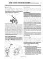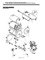
1
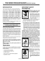
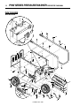
®
P R E S S U R E WA S H E R S
PHW
OPERATOR’S MANUAL
■ PHW2-1100
■ PHW4-2000
LIS T E D
■ PHW3-1100
■ PHW4-3000
®
LANDA, INC. ■ 4275 N.W. Pacific Rim Blvd. ■ Camas, WA 98607 ■ USA
For technical assistance or the Landa Dealer nearest you, call 800-LANDA-4-U (800-526-3248) or (360) 833-9100
or consult our web page at www.landa.com
3
CONTENTS
Introduction ................................................................................................................................... 4
Unpacking..................................................................................................................................... 4
Important Safety Information ......................................................................................................4-5
Component Identification .............................................................................................................. 6
Pre-Operation Check .................................................................................................................... 7
Set Up Procedures ....................................................................................................................... 7
Operating Instructions ................................................................................................................... 7
Shut Down Procedures ................................................................................................................. 7
General Washing Techniques........................................................................................................ 8
Steam Combination ...................................................................................................................... 8
Preventative Maintenance............................................................................................................. 8
Maintenance & Service ............................................................................................................8-10
PHW Exterior Exploded View and Parts List .......................................................................... 11-13
PHW Control Panel Exploded View and Parts List ................................................................. 14-15
PHW Tank Assembly Exploded View and Parts List ...............................................................16-17
PHW Chassis Exploded View and Parts List ......................................................................... 18-19
PHW Pump Assemblies Exploded View and Parts List .......................................................... 20-21
PHW Power Platform Exploded View and Parts List .............................................................. 22-23
Hose & Spray Gun Assembly (All Models) .................................................................................. 24
PHW Float Tank Exploded View and Parts List ........................................................................... 25
Burner Specifications .................................................................................................................. 26
Troubleshooting ..................................................................................................................... 27-32
Preventative Maintenance........................................................................................................... 33
Oil Change Record ..................................................................................................................... 33
Warranty ..................................................................................................................................... 34
Spanish Translations .............................................................................................................. 35-39
Model Number ______________________________
Serial Number ______________________________
Date of Purchase ____________________________
The model and serial numbers will be found on a decal attached to
the pressure washer. You should record both serial number and
date of purchase and keep in a safe place for future reference.
PHW Manual • Form #96-6020 • Revised 9/02
4
PHW SERIES PRESSURE WASHER OPERATOR’S MANUAL
INTRODUCTION
Thank you for purchasing a Landa Pressure Washer.
This manual covers the operation and maintenance of the PHW3-11021D, PHW4-20021A,
PHW4-20021B, PHW4-20021C, PHW4-20021G,
PHW4-20021H, PHW4-20025K, PHW4-20025N,
PHW4-20025P, PHW4-30021A, PHW4-30021B,
PHW4-30021C, PHW4-30021F, PHW4-30021H,
PHW4-30021M, PHW4-30021G, PHW4-30021P,
PHW4-30025N, PHW5-30021B, PHW5-30021C,
PHW5-30021F, PHW5-30021H, PHW5-30021N and
PHW5-30025N washers. All information in this manual
is based on the latest product information available at
the time of printing.
Landa, Inc. reserves the right to make changes at any
time without incurring any obligation.
The PHWS Series was designed for maximum use
of 8 hours per day, 5 days per week.
Owner/User Responsibility:
The owner and/or user must have an understanding of
the manufacturer’s operating instructions and warnings
before using this Landa pressure washer. Warning information should be emphasized and understood. If the operator is not fluent in English, the manufacturer’s instructions and warnings shall be read to and discussed with
the operator in the operator’s native language by the purchaser/owner, making sure that the operator comprehends its contents.
Owner and/or user must study and maintain for future
reference the manufacturers’ instructions.
IMPORTANT SAFETY
INFORMATION
CAUTION: To reduce the risk of
WARNING
CAUTION
injury, read operating instruc-
READ OPERATOR’S
MANUALTHOROUGHLY
PRIOR TO USE.
2. Know how to stop the product and bleed pressures
quickly. Be thoroughly familiar with the controls.
3. Stay alert - watch what you are doing.
4. All installations must comply with local codes. Contact your electrician, plumber, utility company or the
selling distributor for specific details. To comply with
the National Electrical Code (NFPA 70) and provide
additional protection from risk of shock, this product
is provided with a ground fault circuit interrupter
(GFCI) built into the power cord plug (250V 30 amp
or less, 1 PH). If replacement of the plug or cord is
needed, use only identical replacement parts.
DANGER: Improper connection of the equipmentgrounding conductor can result in a risk of electrocution. Check with a qualified electrician or service
personnel if you are in doubt as to whether the outlet
is properly grounded. Do not modify the plug provided
with the product. If it will not fit the outlet, have a
proper outlet installed by a qualified electrician.
WARNING
This manual should be considered a permanent
part of the machine and should remain with it if
machine is resold.
When ordering parts, please specify model and
serial number.
UNPACKING
Carefully unpack your new LANDA washer and check
contents against packing slip. Basic equipment with each
machine includes:
1. Pressure washer assembly
2. High pressure discharge hose
3. Wand assembly
4. Spray gun on machines where applicable
5. Operator’s manual
tions carefully before using.
1. Read owner's manual thoroughly. Failure to follow instructions could cause malfunction
of the machine and result in
death, serious bodily injury and/
or property damage.
WARNING: Do not use gasoline,
crankcase drainings or oil containing gasoline, solvents or alcohol. Doing so will result in fire and/
or explosion.
WARNING: Risk of explosion-do
not spray flammable liquids.
5. In oil burning models, use only
kerosene, No. 1 home heating
fuel, or diesel. If diesel is used, add a soot remover
to every tankful.
RISK OF EXPLOSION:
DO NOT USE WITH
FLAMMABLE
LIQUIDS.
WARNING
RISK OF
ASPHYXIATION.
USE THIS PRODUCT
ONLY IN A WELL
VENTILATED AREA.
LANDA PHW • 9/02
WARNING: Risk of asphyxiation.
Use this product only in a well
ventilated area.
6. Avoid installing machines in
small areas or near exhaust
fans. Adequate oxygen is
needed for combustion or dangerous carbon monoxide will result.
PHW SERIES PRESSURE WASHER OPERATOR’S MANUAL
WARNING
RISK OF EXPLOSION:
DO NOT USE WITH
FLAMMABLE
LIQUIDS.
WARNING: Risk of fire. Do not add
fuel when machine is operating or
still hot.
7. Turn machine off before refueling. Fire and/or explosion may
occur if this is not done. Refuel
in a well ventilated area.
WARNING: Keep water spray
away from electrical wiring or
fatal electrical shock may result.
Read warning tag on electrical
cord.
8. To protect the operator from
KEEP WATER SPRAY
electrical shock, the machine
AWAY FROM
must be electrically grounded.
ELECTRICAL WIRING.
It is the responsibility of the
owner to connect this machine
to a UL grounded receptacle of proper voltage and
amperage ratings. Do not spray water on or near
electrical components. Do not touch machine with
wet hands or while standing in water. Always disconnect power before servicing.
WARNING
CAUTION: Spray gun kicks back — hold with both
hands.
9. Grip cleaning wand securely with both hands before
starting the cleaner. Failure to do this could result in
injury from a whipping wand.
WARNING
RISK OF EXPLOSION:
DO NOT USE WITH
FLAMMABLE
LIQUIDS.
WARNING
WARNING: Flammable liquids
can create fumes which can ignite
causing property damage or severe injury.
10. Oil burning appliances shall be
installed only in locations where
combustible dusts and flammable gases or vapors are not
present. Do not store or use
gasoline near this machine.
5
12. Never make adjustments on machine while it is in
operation.
WARNING: High pressure spray
can cause paint chips or other
particles to become airborne and
fly at high speeds.
13. Eye safety devices, foot protection and other protective clothUSE PROTECTIVE
ing must be worn when using
CLOTHING WHEN
this equipment.
OPERATING.
14. The spray gun should not be
operated with the trigger in the off position for extensive periods of time as this may cause damage to
the pump. Check to make sure burner shuts off with
spray gun closed.
15. Protect from freezing.
16. Protect discharge hose from vehicle traffic and sharp
objects.
17. To prevent serious injury, be certain quick coupler
on discharge hose has locked before using pressure washer.
18. Before disconnecting discharge hose from hot water outlet, turn off burner and open spray gun to allow water to cool to 100°, then turn off pump motor
and water supply and open spray gun to relieve back
pressure in hose. This will prevent coil damage from
thermal expansion.
19. Do not allow acids, caustic or abrasive fluids to pass
through the pump.
20. Inlet supply water must be cold and clean fresh water.
21. The best insurance against an accident is precaution and knowledge of the machine.
22. LANDA will not be liable for any changes made to
our standard machines or any components not purchased from LANDA .
23. To reduce the risk of injury, close supervision is necessary when a product is used near children. Do not
allow children to operate the pressure washer. This
machine must be attended during operation.
WARNING
WARNING: Risk of injection or severe injury to persons. Keep clear
of nozzle. Do not touch or direct
discharge stream at persons. This
machine is to be used only by
trained operators.
HIGH PRESSURE
STREAM CAN
PIERCE SKIN AND
TISSUES.
CAUTION: Hot discharge fluid. Do
not touch or direct discharge
stream at persons.
11. High pressure developed by these machines will cause
personal injury or equipment damage. Use caution
when operating. Do not direct discharge stream at
people, or severe injury or death will result.
LANDA PHW • 9/02
6
PHW SERIES PRESSURE WASHER OPERATOR’S MANUAL
COMPONENT IDENTIFICATION
ALL MODELS
Discharge
Nipple
Quick Coupler
& Collar
Pump & Burner
Switch
High Pressure
Nozzle
Hour
Meter
High Pressure/
Steam Valve
Adjustment
Detergent
Bucket
(not included)
Stackless Top
Adapter Kit
(optional #30-199)
All Three Phase
Machines Plus
PHW4-20021G
PHW4-30021A
Nozzle Quick
Coupler
Water Supply
(not included)
Control
Handle
Float Tank
Brass Soap
Nozzle
Variable
Pressure
Control
Wand
PHW4-20021A
PHW3-11021D
PHW2-11021D
Power Supply
20 Amp
Water
Supply Hose
(not included)
GFCI
Inlet
Swivel
Connector
Spray Gun
Trigger
Fuel
Tank
LANDA PHW • 9/02
Hand
Brake
PHW SERIES PRESSURE WASHER OPERATOR’S MANUAL
24. Do not overreach or stand on unstable support. Keep
good footing and balance at all times.
25. Follow the maintenance instructions specified in the
manual.
26. Do not operate this product when fatigued or under
the influence of alcohol or drugs. Keep operating area
clear of all persons.
PRE-OPERATION CHECK
❑ Check pump oil level. (Use SAE 30W non-detergent
oil). Dipstick is located on top of pump.
❑ Cold water supply (minimum 6 gpm, 5/8", 20 psi)
❑ Hose, wand, nozzle (nozzle size per serial plate)
❑ Water filter (intact, non restrictive)
❑ Open spray gun to relieve pressure before starting.
SET-UP PROCEDURES
Machines must be stored indoors when not in use.
❑ Location of machine is important. Avoid installing
near combustible material or in poorly ventilated areas.
❑ Electrical connection to machine should be the
proper voltage, phase and amperage. See specifications for particular model. Plug the power cord into
a grounded receptacle. The PHW2-11021D and
PHW3-11021D each require a 20 amp receptacle
to comply with UL 1776 standards.
❑ Water source for machines should be supplied by a
5/8" I.D. garden hose with a city water pressure of
not less than 30 PSI. If the water supply is inadequate, or if the garden hose is kinked, the machine
will run very rough and the burner will not fire.
❑ Fill fuel tank with proper fuel.
❑ Adding exhaust vent pipe to your oil fired burner is
not recommended because it restricts air flow. This
causes carbon build-up, which affects the operation
and increases maintenance on the coil. If a stack
must be used, refrain from using 90 degree bends. If
the pipe can not go straight up then use only 45 degree bends and go to the next larger size pipe. The
overall pipe length must not exceed 6 feet in length.
7
❑ Connect the high pressure hose quick coupler to discharge nipple by sliding the quick coupler collar back
and inserting quick coupler on coupler nipple and
pushing the quick coupler collar forward to secure it.
❑ Connect the wand, nozzle, hose and spray gun
(where applicable). Use teflon tape on pipe thread
connections to avoid water leaks (see component
identification).
❑ Plug the power cord into the proper power supply.
(Refer to serial plate for information.)
❑ Grip spray gun and wand handle securely.
❑ Turn the pump and burner switch to the pump position.
When a steady stream of water flows from the spray
gun and wand, turn the pump and burner switch to
the burner position. The burner will light automatically when the spray gun trigger is pulled.
❑ Turn the variable pressure control handle clockwise
to increase pressure.
❑ Place detergent hose into detergent container and
open detergent valve. NOTE: Do not run this machine more than five minutes with spray gun closed.
When spray gun is closed more than two minutes,
the pump protector may open to allow hot water to
dump on the ground; thus allowing cold water to reenter the pump.
SHUT DOWN PROCEDURES
❑ Place detergent line in a bucket of water allowing
detergent to be flushed from system. Then turn detergent valve off.
❑ Push burner switch off or turn switch to pump position and open trigger on spray gun, allowing water
to flow, which will cool down the heating coil.
❑ After water has cooled, turn the pump and burner
switch to the OFF position.
❑ Turn water off.
❑ Protect from freezing (see Winterizing Procedures).
OPERATING INSTRUCTIONS
❑ Read safety, installation and preventative maintenance instructions before starting machine.
❑ Connect the water supply hose to the float tank inlet
swivel connector and turn on water supply.
❑ Check fuel tank level.
LANDA PHW • 9/02
8
PHW SERIES PRESSURE WASHER OPERATOR’S MANUAL
GENERAL WASHING
TECHNIQUES
This machine is equipped with a spray gun and various
nozzle patterns, use the wide patterns on easy soil removal jobs and the narrow patterns on the more difficult
jobs or tight areas such as cracks and holes.
In most cases, faster results and better detergent
economy will be obtained by applying the detergent and
letting it “set” for a few minutes, prior to rinsing. This enables it to do its soil penetrating and loosening work.
Most cleaning work terminates with a high pressure rinse
as part of the normal cleaning procedure. In some cases,
however, the last operation may be the application of a
detergent (sanitizing, for example). After such work, run
machine for 20 - 30 seconds to clear the pump and lines.
Do not run anything through this machine that will damage the steel heating coil and pump.
STEAM COMBINATION
❑ Open the pump access panel.
❑ Turn the unloader knob counterclockwise lightly until you feel resistance. (Detergent will not siphon when
the steam valve is opened.)
❑ Turn the thermostat knob to the 270° mark. (The thermostat is a high limit device and does not regulate
temperature).
❑ To stop, reverse steps 1 to 3 and set all controls to
their original settings.
❑ Turn burner switch off, open trigger on spray gun
and allow water to cool.
❑ Never run pump dry for extended periods of time.
❑ Periodically delime coils as per instructions.
❑ If machine is operated with smoky or eye-burning
exhaust, coils will soot up and prevent water from
reaching maximum operating temperature. See section on burner adjustments.
MAINTENANCE AND SERVICE
Pump Lubrication:
Use only LANDA SAE 30 weight, non-detergent oil.
Change oil after first 50 hours of use. Thereafter, change
oil every three months or at 500 hour intervals. Oil level
should be checked through use of dipstick found on top
of pump or red dot visible through oil gauge window. Oil
should be maintained at that level.
Fuel:
Use clean (not contaminated with water and debris) kerosene, No. 1 home heating fuel or diesel. Drain fuel tank
and replace fuel filter every 100 hours of operation.
Electrode Setting - Wayne:
Gap
1/8"
Electrodes
1/8"
3/8"
1/2"
3/16"
2-7/8"
Nozzle Adapter
Side View
Top View
Periodically Check Wiring Connections. If Necessary
To Adjust Electrodes, Use Diagram
PREVENTATIVE
MAINTENANCE
❑ Use clean fuel - kerosene, No. 1 home heating fuel
or diesel. Clean or replace fuel filter every 100 hours
of operation. Avoid water contaminated fuel as it will
seize up the fuel pump. De-soot coils monthly or use
an additive if diesel is being used.
❑ Check to see that water pump is properly lubricated.
❑ Follow winterizing procedure to prevent freeze damage to pump and coils.
❑ Always flush detergents from system after use.
❑ If water is known to be high in mineral content, use a
water softener on your water system or use a LANDA
recognized coil cleaning detergent.
❑ Do not allow acidic, caustic or abrasive fluids to be
pumped through the system.
❑ Always use high grade quality LANDA cleaning detergents.
Electrode Setting Beckett:
5/32" Gap
Electrode
5/16" Above
Nozzle
1/16"
Top View
Side View
Periodically Check Wiring Connections. If Necessary
To Adjust Electrodes, Use Diagram
LANDA PHW • 9/02
PHW SERIES PRESSURE WASHER OPERATOR’S MANUAL
9
Ignition Circuit:
Burner Nozzle:
Periodically inspect wires, spring contact and electrodes
for condition, security and proper spacing. Transformer
test: CAUTION: 10,000 volts — use defect free insulated screwdriver and keep fingers off blade! Lay blade
across one contact: OK if arc will span 1/2" between end
of blade and other contact (see illustration).
Keep tip free of surface deposits by wiping with clean,
solvent-saturated cloth, being careful not to plug or enlarge nozzle. For maximum efficiency, replace nozzle
each season.
Transformer Check:
Fuel Control System:
These machines utilize a fuel solenoid valve located on
the fuel pump to control the flow of fuel to the combustion chamber. This solenoid, which is normally closed, is
activated by the flow switch. When an operator releases
the trigger on the spray gun, the unloader goes into a
by-pass mode, thus stopping electrical current to the fuel
solenoid coil. With the solenoid closed, the fuel supply to
the combustion chamber ceases. Periodic inspection to
insure that the fuel solenoid valve functions properly is
recommended. This can be done by operating the machine and checking to see that when the spray gun is in
the off position, the burner is not firing.
Fuel Pressure Adjustment:
To adjust fuel pressure, turn the adjusting screw clockwise to increase, counterclockwise to decrease. Do not
exceed 200 PSI. NOTE: When changing fuel pump, a
bypass plug must be installed in return line port or fuel
pump will not prime.
Air Shutter
Locking Screw
Air Adjustment:
Machines are preset and performance tested at the factory elevation of 100'. A onetime initial correction for your
location will pay off in economy, performance and extended service life. If a smoky or eye-burning exhaust is
being emitted from the stack, two things should be
checked. First, check the fuel to be certain that kerosene or No.1 home heating fuel is being used. Next, check
the air adjustment on the burner. An oily, smoky fire indicates a lack of air and the air band should be moved to
allow the air to flow through the burner. Sharp eye-burning fumes indicate too much air flowing through the combustion chamber. The air band should be readjusted to
allow less air to flow through the burner.
To adjust, start machine and turn burner ON. Loosen
two locking screws found in the air shutter openings (refer to illustration) and close air shutter until black smoke
appears from burner exhaust vent. Note air band position. Next, slowly open the air shutter until white smoke
just starts to appear. Turn air shutter halfway back to the
black smoke position previously noted. Tighten locking
screws.
If the desired position cannot be obtained using only the
air shutter, lock the air shutter in as close a position as
can be obtained, then repeat the above procedure on
the air band setting.
Cleaning of Coils:
In alkaline water areas lime deposits can accumulate
rapidly inside the coil pipes. This growth is increased by
the extreme heat buildup in the coil. In areas where alkaline water is an extreme problem, periodic use of
LANDA Deliming Powder will remove lime and other deposits before coil becomes plugged. (See Deliming instructions for use of LANDA Deliming Powder).
Air Shutter
Deliming Coils:
Air Band
Periodic flushing of coils is recommended.
1. Fill the float tank with 4 gallons of water, then add 1
lb. of deliming powder. Mix thoroughly.
2. Remove nozzle from wand assembly and put spray
gun and wand assembly into float tank. Attach a nylon stocking to the end of the wand to collect debris.
3. Turn pump switch on, allowing solution to be pumped
through coils and back into the float tank. Solution
should be allowed to circulate 2 - 4 hours.
Air Shutter
Locking Screw
Air Band Locking
Screw
LANDA PHW • 9/02
10
PHW SERIES PRESSURE WASHER OPERATOR’S MANUAL
4. After circulating solution, clean and drain float tank
and flush entire system with fresh water. Replace
nozzle in wand.
Unloader valves are preset and tested at the factory before shipping. Occasional adjustment of unloader may
be necessary to maintain correct pressure. (See section
in manual and consult your local LANDA Dealer for the
correct procedures in adjusting the unloader valve.)
3. Remove all the fittings from the discharge and inlet
side of the coil.
4. Remove the burner assembly from the combustion
chamber.
5. Remove 3 - 3/8" bolts from either side of coil and
tank assembly (these bolts are used to fasten tank
and handles to chassis).
6. Remove the two 3/8" nuts which are underneath the
bottom wrap (to keep the coil from moving).
7. Remove tank top wrap exposing insulation and coil.
Carefully bend insulation tabs at exhaust stack.
8. Carefully fold back the insulation and remove the
coil.
9. Replace or repair any insulation found to be torn or
broken.
10. Reinstall new or cleaned coil by reversing steps 8
through 1.
Winterizing Procedure:
Temperature and Pressure Relief Valve:
Damage due to freezing is not covered by warranty. Adhere to the following cold weather procedures whenever
the washer must be stored or operated outdoors under
freezing conditions.
During the winter months, when temperatures drop below 32° F, protecting your machine against freezing is
necessary. Siphoning a small amount of antifreeze into
the system is recommended. This is done by pouring a
50/50 mix of antifreeze and water into the float tank and
then siphoning 100% antifreeze through the detergent
line with the pump on. If compressed air is available, an
air fitting can be screwed into the float tank strainer fitting and, by injecting compressed air, all water will be
blown out of the system.
(Pump Protector)
Low Pressure Diagnosis:
High Limit Hot Water Thermostat:
Refer to the low pressure section of the troubleshooting
guide. If, by referring to the guide, the trouble is found to
be either the unloader or pump, your next step is to determine which is the problem. This can be done by eliminating the unloader from the system and attaching the
discharge hose directly to the pump. If high pressure is
present, then the unloader needs repairing or replacing.
For safety, machines are equipped with a high limit snap
switch. If the temperature of the water should exceed its
operating temperature, the high limit snap switch thermostat will turn the burner off until the water cools, then
it will automatically reset itself.
Spray Nozzles:
Each machine is equipped with one spray nozzle. Different spray nozzles are calibrated for each machine depending on the flow and pressure of that particular model.
Spray nozzles vary in bore size and angle of spray. Popular spray angles are 0°, 15°, 25° and 40°. When ordering, please specify size and angle of nozzle. Nozzle size
for each machine is located on the serial plate.
Unloader Valves:
CAUTION: When using this procedure to test components, keep spray gun open at all times.
Coil Removal:
Removal of the coil because of freeze breakage or to
clean soot from it, can be done quickly and easily.
1. Disconnect hose from pump/unloader to inlet side
of coil.
2. Disconnect the electrical connections to the thermostat or remove thermostat sensor.
Machines with spray gun control offer the operator the
convenience of stopping and starting the flow of water at
the end of the discharge hose. When the spray gun stops
the flow of water, the unloader valve, back at the machine, opens and recycles the cold water back to the
inlet side of the pump. Recycling for longer than five minutes causes the cold water within the pump to heat up.
To avoid damage to the pump, a temperature and pressure relief valve is installed next to the inlet side of the
pump that will open in the event the water temperature
exceeds 140° F. Therefore, while operating the machine,
do not leave the spray gun closed for an extended period of time.
Rupture Disk:
If pressure from pump or thermal expansion should exceed safe limits, the rupture disk will burst, allowing high
pressure to be discharged through hose to ground. When
the disk ruptures, it will need to be replaced. Torque
replacement disk to 35 lbs.
LANDA PHW • 9/02
PHW SERIES PRESSURE WASHER OPERATOR’S MANUAL
PHW EXTERIOR VIEW
ALL MODELS
25
14
29
18
33
19
12
5
11
13
30-199
32
7
31
30
17
27
24
6
26
20
8
23
1
2
15
10
22
9
16
21
3
4
28
LANDA PHW • 9/02
11
12
PHW SERIES PRESSURE WASHER OPERATOR’S MANUAL
PHW EXTERIOR VIEW
ALL MODELS PARTS LIST
ITEM
PART NO.
DESCRIPTION
1
10-02025A
Label, “HOT” Warning Exhaust 1
2
2-01101
Grip, Handle (Waffle), 1"
2
3
10-08018
Label, Warning Service Cord
1
4
10-020110
Label, Use Only Kerosene
1
5
2-0103
Grommet, 1/8", Rubber
4
6
6-05152
Strain Relief, Plastic (3-1100)
1
6-051595
Fitting, Strt, LQTITE
(4-2000, 4-3000, 5-3000)
1
6-05170
7
Strain Relief, 3/4"
(4-2000G, 4-3000A,G)
1
ITEM
PART NO.
DESCRIPTION
6-0108
Cord, Service, SOWA, 10/3 /ft.
(4-2000K)
15
6-010690
GFCI, 240V 1PH, 40 Amp, 36',
8/3 Cord (4-2000G,4-3000A,G) 1
24
7-01471
Insulation Gasket, Stackless Top
(optional 30-199)
1
25
10-99083
Label, Warning, Hot Water
1
26
90-20041
Collar, 5/8" Bore Shaft, 3010
4
27
95-07101012
Axle, 27", PHW
2
28
95-07121010S Chassis, All Models
29
2-2007
Nipple, 3/8" x 3/8" NPT ST Male1
Label, PHW Plat. Series
1
23
QTY
1
Screw, 1/4" x 3/4", SS Tek
(optional 30-199)
4
30
10-99056
8
95-07121014S Top Wrap, Stainless Steel
1
31
10-020PHW
Label, PHW
1
9
95-07121015
Wrap, Bottom, Stainless Steel 1
32
10-2031100
Label, 3-1100
1
10
95-07121110
Handle “J”
2
10-2042000
Label, 4-2000
1
11
7-10049
Adapter, Flue, 8" Stackless Top
(optional 30-199)
1
10-2043000
Label, 4-3000
1
4-12804000
12
10-080221
Label, PHW, Control Panel
1
Nozzle, SAQCMEG, 0004, Red
(4-3000)
1
13
95-07121024
Control Box, Series II
1
4-12804015
2-01107
Weather-stripping /ft.
4
Nozzle, SAQCMEG, 1504, Yellow
(4-3000)
1
90-19942
Screw, 10/32" x 3/4",
Hex Wash Slot
4-12804025
2
Nozzle, SAQCMEG, 2504, Green
(4-3000)
1
4-12804040
Nozzle, SAQCMEG, 4004, White
(4-3000)
1
4-12804500
Nozzle, SAQCMEG, 00045,
Red, (4-2000K)
1
4-12804515
Nozzle, SAQCMEG, 15045,
Yellow, (4-2000K)
1
4-12804525
Nozzle, SAQCMEG, 25045,
Green, (4-2000K)
1
14
90-3003
QTY
15
2-01104
Trim, 1/16" Black, 750B-2
16
2-01157
Cap, PHW, w/ Fuel Gauge, 14" 1
17
2-1905
Strainer, 1/4" w/ Check Valve
1
18
2-3015
Valve Control, Metering
1
19
4-02080000
Tube, 1/4" x 1/2", Clear Vinyl /ft.8
33
/ft. 2
20
4-0303
Wheel & Tire Assy, 4"
21
6-01060
Cord, w/ GFCI Plug, 120V 20A,
36 ft. (3-1100)
1
4-12804540
Cord, w/ GFCI 240V, 30A, 36 ft.
(4-2000A)
1
Nipple, SAQCMEG, 40045,
White (4-2000K)
1
4-12805000
Nipple, SAQCMEG, 0005,
Red (4-2000N/P, 5-30025N)
1
22
23
6-01059
6-0105
6-01041
6-0109
4
Cord, Service, SEO, 12/4 /ft.
(4-2000C/N/P, 4-3000C/F/N/P) 36
4-12805015
Cord, Service, SJOWA, 12/3
(3-1100K)
Nozzle, SAQCMEG, 1505,
Yellow (4-2000N/P)
1
4-12805025
Nozzle, SAQCMEG, 2505,
Green (4-2000N/P)
1
Nozzle, SAQCMEG, 4005,
White (4-2000N/P)
1
Cord, Service, SEO 10/4 /ft.
(4-2000B/H, 4-3000B/H/M)
15
36
LANDA PHW • 9/02
4-12805040
PHW SERIES PRESSURE WASHER OPERATOR’S MANUAL
PHW EXTERIOR VIEW
ALL MODELS PARTS LIST CONTINUED
ITEM
PART NO.
DESCRIPTION
35
4-12805500
Nozzle, SAQCMEG, 00055,
Red (3-1100)
1
4-12805515
Nozzle, SAQCMEG, 15055,
Yellow (3-1100)
1
4-12805525
Nozzle, SAQCMEG, 25055,
Green (3-1100)
1
4-12805540
Nozzle, SAQCMEG, 40055,
White (3-1100)
1
4-12806000
Nozzle, SAQCMEG, 0006,
Red (4-2000)
1
4-12806015
Nozzle, SAQCMEG, 1506,
Yellow (4-2000)
1
4-12806025
Nozzle, SAQCMEG, 2506,
Green (4-2000)
1
Nozzle, SAQCMEG, 4006,
White (4-2000)
1
4-12806040
QTY
LANDA PHW • 9/02
13
14
PHW SERIES PRESSURE WASHER OPERATOR’S MANUAL
PHW CONTROL PANEL
ALL MODELS
4
20
19
6
1
24
23
5
22
21
18
2
30
4
32
15
33
16
17
10
11
14
28
7
27
26
5
29
25
9
12
8
13
17
16
3
31
LANDA PHW • 9/02
PHW SERIES PRESSURE WASHER OPERATOR’S MANUAL
15
PHW CONTROL PANEL
ALL MODELS PARTS LIST
ITEM
1
PART NO.
DESCRIPTION
6-4000
Contactor, CH, CE15BNS3AB,
(4-2000C)
1
6-4004
Contactor, CH, CE15CNS3AB,
(4-3000C/F)
1
6-4007
Contactor, CH, CE15DNS3AB,
(4-2000B/H)
1
6-4010
2
7
8
6-021595
Din Rail Track
9
6-0517
Strain Relief, 3/4"
1
10
6-051597
Bushing, Terminal
1
11
6-0515
Connector, Flex, 90°, 3/8"
1
12
6-0122
Conduit, Flex, Alum, 3/8" /ft.
2
6-01220
▲ Conduit, Bushing, Anti-Short 2
6-05152
Strain, Plastic (2-1100, 3-1100) 1
13
QTY
/inch
5
Fitting, Strt, LQ Tite
(4-2000, 4-3000)
1
6-5009
Overload, CH, C316FNA3P,
7.5-11 Amps (4-2000C)
6-05170
Strain Relief, 1"
(4-2000G, 4-3000A/G)
1
6-05172
▲ Lock Nut
1
14
2-01411
Bushing, 1" Snap
1
15
2-3015
Valve, Metering
1
16
2-1085
Hose Barb, 1/4" Barb x
1/4" ML Pipe
2
1
6-5010
Overload, CH, C316FNA3Q, 10-14
Amps (4-3000C/F)
1
6-5011
Overload, CH, C316FNA3R,
13-19 Amps (4-2000B/H)
6-020201
6-6003
Overload, CH, C316FNA3S,
18-24 Amps (4-3000B/H/M)
1
1
Overload, CH, C316FNA3C,
29-42 Amps (4-3000A)
1
Switch, 3 Pos., 115V-230V
1-3PH
1
Transformer, Micron,
208/277V-120V, .500 KVA
(4-3000H)
1
Transformer, Micron, 240/480120/240V, .500 KVA (4-2000C,
4-3000C)
1
6-05234
Transformer, 600V-120V, 1.00 KVA
(4-3000F)
1
6-60101
Transformer, Micron, 240/480120V, .050 KVA/Glass
(4-2000A/B/H, 4-3000A/B/M) 1
6-60141
6
DESCRIPTION
6-051595
6-60021
5
PART NO.
Contactor, CH, CE15HNS3AB-09,
(4-3000A)
1
6-5015
4
Contactor, CH, CE15ENS3AB,
(4-3000B/H/M)
1
ITEM
6-4018
6-5012
3
QTY
6-02294
6-022970
17
2-9000
Clamp, Screw #4
2
18
2-0103
Grommet, 1/8", Rubber
1
19
2-01168
Cap, Rubber, Capacitor
3
20
90-017
Nut, 10/32", Keps
3
21
2-0100193
Clamp, 2" Click
3
22
90-1999
Screw, 10/32" x 3/4" BH SOC
3
Start Capacitor (4-3000A)
2
Run Capacitor (4-3000A)
1
23
24
10-02032
▲ Label, Discharge Capacitors
(4-3000A)
1
90-1040
Screw, 10/32" x 1/2" Sckt, CAP 4
26
6-03565
Fuse Block (4-3000C/F/N)
1
27
6-02306
Fuses, 3 Amp, 600V
(4-2000, 4-3000C/F)
2
25
Transformer, Micron, 208V-120V,
.075 KVA (4-2000G)
1
28
Fuse, ATMR, 1 Amp, 240V
(4-2000A/B/G/H,
4-3000A/B/H/M)
2
Fuse, Paper, Buss, FNM-1/2,
250V (4-2000A/B/G/H,
4-3000A/B/H/M)
29
6-023090
Paper Fuse, FNM5 (4-2000C) 2
90-16
Screw, 8/32" x 3/4" (4-2000,
4-3000C/F)
1
90-200490
Nut, 8/32" Keps (4-2000,
4-3000C/F)
1
90-19942
Screw, 10/32" x 3/4", Hex
Wash Slot
2
Nut, Cage, 10/32" x 16 Ga.
2
1
6-022910
Fuse, Paper, Buss, FNM 8, 250V
(4-3000C/F)
1
30
90-2018
31
10-08021
Label, Disconnect Power Supply 1
6-02292
Fuse, 10 amp MDL, 380V
32
4-02090000
Hose, 1/4" x 1/2", Braided Vinyl 3
33
11-1042
Label, Ground
1
LANDA PHW • 9/02
1
16
PHW SERIES PRESSURE WASHER OPERATOR’S MANUAL
PHW TANK ASSEMBLY
ALL MODELS
1
21
22
23
18
17
19
24
26
16
20
13
7
6
2
25
To
Unloader
5
7
8
38
4
12
6
26
11
27
10
9
14
34
3
35
To Fuel
Tank
36
31
28
29
33
30
14
To Fuel
Tank
32
33
37
15
LANDA PHW • 9/02
PHW SERIES PRESSURE WASHER OPERATOR’S MANUAL
17
PHW TANK ASSEMBLY
ALL MODELS PARTS LIST
ITEM
PART NO.
DESCRIPTION
1
10-99083
Label, Warning Hot Water
QTY
2
Burner Assembly, See Burner Spec's Page 26
1
ITEM
PART NO.
DESCRIPTION
23
7-01484
Insulation, Blanket - Die Cut, 28"1
QTY
24
90-20040
Nut, 3/8" Flange Whiz Loc
2
3
2-0039
Cross, 1/2" Female, Steel
3
25
90-1019
Bolt, 3/8" x 1-3/4"
2
4
2-00602
Elbow, 1/2" JIC x 1/2" Fem.
1
26
90-4002
Washer, Flat, SAE, 3/8"
5
5
2-00091
Nipple, Galv., 1/2" x 3", Sch. 80 1
27
90-2002
Nut, ESNA, NC, 3/8"
3
6
95-07121113
Insulation Retainer
2
28
2-1022
Elbow, Street, 1/4"
1
2
29
2-1002
Nipple, Close, 1/4"
1
30
2-9905
Filter, Fuel Oil/H2O Separator
1
2-99051
Element, Fuel/H2O Separator
1
31
2-1089
Hose Barb, 90°, 1/4" Barb x
1/4" Pipe
1
4
7
7-0144
Gasket, Burner Plate
8
4-02047725
Hose, Pres. Loop, 100R2,
25" x 3/8"
1
9
2-00101
Nipple, Galv., 1/2" x 4", Sch. 80 1
10
2-00120
Nipple, Galv., 1/2" x 5", Sch. 80 1
11
2-00241
Coupling, 1/2" x 3/8"
1
32
2-9000
▲ Clamp, Screw #4
12
2-2007
Nipple, 3/8" x 3/8" NPT ST Male1
33
4-02100000
Hose, 1/4", Push-on, Fuel Line 2
13
7-0140
Insulation, Front Head, No Hole 1
34
2-3480
14
2-3408
Rupture Disk Assy, 8000 PSI
(All models)
Rupture Disk Replacement,
8000 PSI (All Models)
1
1
35
2-90041
Screw Clamp, #16
1
36
2-1085
Hose Barb 1/4" Barb x 1/4"
ML Pipe
1
37
4-02130050
Hose, 7/8" Push On /ft.
2
38
6-0516
Strain Relief, 1/2"
1
15
4-05091
Switch, Snap, 275 Dr Hi-Limit
1
16
95-07121015
Bottom Wrap, Stainless Steel
1
17
18
19
20
95-07121212
7-01430
7-0141
7-12484
Coil Replacement, Schedule 80
w/ Steel Wrap
1
▲ Not Shown
Insulation, Blanket w/ No Foil
24" x 57"
1
Insulation, Burner Head,
w/ Hole
1
Gasket Standard - Large
2
21
95-07121014S Top Wrap, Stainless Steel
22
2-01104
1
Trim, 1/16" Black, 750B-2 /ft.3.25
LANDA PHW • 9/02
18
PHW SERIES PRESSURE WASHER OPERATOR’S MANUAL
PHW CHASSIS
ALL MODELS
42
43
30
44
10
45
7
34
44
Fuel Line
to Burner
40
8
1
36
6
36
35
25
35
3
30
5
2
9
29
4
32
26
33
17
12
31
24
14
40
22
41
18
23
37
27
21
20
40
38
13
39
11
4
28
19
16
15
LANDA PHW • 9/02
PHW SERIES PRESSURE WASHER OPERATOR’S MANUAL
19
PHW CHASSIS
ALL MODELS PARTS LIST
ITEM
1
2
PART NO.
DESCRIPTION
95-07121017
Panel, Rear Access
1
10-02028
▲ Label, Warning Exposed Pulleys
90-50031
QTY
ITEM
PART NO.
DESCRIPTION
QTY
23
90-1999
Screw, 10/32" x 3/4",
BH SOC CS
1
24
90-40002
Washer, 1/4", SAE, Black Zinc 4
Knob, Black 3 Pt, 5/16"-18 x 1" 2
25
90-2018
Nut, Cage, 10/32" x 16 Ga.
6
6
90-2023
▲ Nut, Cage, 5/16"-18, Black
2
26
90-20231
Nut, Cage, 1/4" x 12 Ga.
2
3
90-4001
Washer, 5/16", Flat SAE
2
27
2-1042
4
90-1995
Screw, 1/4" x 1/2", BH SOC CS 4
Tee, 1/2" Street
(4-2000, 4-3000)
1
5
90-2000
Nut, 1/4", ESNA, NC
6
95-07121010S Chassis, All
1
7
2-01101
Grip, Handle (Waffle), 1"
2
8
95-07121110
Handle, “J”, PHW
2
9
2-01157
Cap, PHW w/ Fuel Gauge, 14" 1
10
2-010063
Dip Tube, Plastic, 12"
11
2-01164
Tank, Float, Universal Plastic
12
28
2-1062
Elbow, 1/2" JIC x 1/2", 90°
(4-2000, 4-3000)
1
29
10-020110
Label, Use Only Kerosene
1
30
2-010066
Elbow, Fuel, Tank
1
31
90-5016
Nut, 3/8" - 16 NC Kimdorf
w/ Spring
2
1
32
90-4002
Washer, 3/8", SAE, Flat
2
1
33
90-1018
Bolt, 3/8" x 1-1/2", NC
2
95-07121207
Lid & Hinges, Plastic Float Tank 1
34
90-10201
Bolt, 3/8" x 2-1/4"
6
13
10-99079
Label, Stripe
1
35
90-2019
Nut, Cage, 3/8" x 16 GA
2
14
95-07101012
Axle, 27", PHW
2
36
90-2002
Nut, 3/8" ESNA
4
15
4-02100013
Inlet Hose, Supply Water, 13"
(4-2000, 4-3000)
1
37
95-07290086
Assy, Lever, Brake
1
38
90-1992
Bolt, 3/8" x 3/8" Sckt Shdr
1
90-2001
Nut, 5/16" ESNA
1
16
4-02100009
2
Inlet Hose, Supply Water, 11"
(All Models)
1
39
17
4-0303
Wheel & Tire Assembly, 4"
4
40
90-4002
Washer, 3/8" Flat
9
18
90-20041
Collar, 5/8" Bore Shaft 3010
4
41
2-01212
Cap, Vinyl Flat, Yellow
1
42
2-1085
Hosebarb, 1/4" Barb x 1/4" ML
Pipe
1
19
2-1053
Nipple, 1/2" JIC x 1/2" Pipe
(All Models)
1
20
95-07162007
Hose Connection Bracket
1
43
2-9000
Clamp, Screw #4
21
2-10942
Swivel, 1/2" MP x 3/4" GHF
1
44
4-02100000
Hose, 1/4" Push-on, Fuel Line 2
22
2-1902
Strainer, Inlet Garden Hose
1
45
2-010061
Bushing, Mount, Rubber
▲ Not Shown
LANDA PHW • 9/02
4
2
20
PHW SERIES PRESSURE WASHER OPERATOR’S MANUAL
PHW PUMP ASSEMBLIES
8
11
7
To
Coil
Inlet
10
19
21
20
4
16
17
18
5
12
13
1
6
9
To Detergent
Valve
12
15
6
2
14
5
3
PHW 3-11021D
To Float
Tank
8
PHW - ALL MODELS
11
10
To
Coil
Inlet
7
19
21
20
4
16
17
9
6
12
13
5
1
12
14
5
2
3
To Float Tank
6
LANDA PHW • 9/02
To
Detergent
15
Valve
PHW SERIES PRESSURE WASHER OPERATOR’S MANUAL
21
PHW PUMP ASSEMBLIES
PARTS LIST
ITEM
1
PART NO.
DESCRIPTION
95-07121112
Rail, Pump Combo
QTY
6-02174
Replacement, Reed
1
4-02047725
Hose, 25" x 3/8", 100R2
Pres Loop
1
▲ Nut, Cage, 3/8" x 12 GA
2
Washer
4
3
1-99364400
Screw
4
4
5-2302
Pump, General, T-991
(3-1100)
5-2271
Pump, AR, XRA45G30 HN
4-3000N)
1
Pump, AR, XMA35G25N
(3-1100K, 4-2000K/N/P)
1
Pump, General, T-1011
(4-2000)
1
Pump, General, TS-2021
(4-3000)
1
3
1
/ft.
QTY
11
1-96710600
5-2307
DESCRIPTION
10
90-2020
5-2304
PART NO.
1
2
5-2273
ITEM
5
4-02110000
Hose, 1/2" Push-On
6
2-1105
Swivel, 1/2" JIC Fem., Push-On 3
7
2-0079
Swivel, 1/2" JIC Fem., 3/8" Male1
8
2-0053
Elbow, 1/2" JIC x 3/8", 90°
1
9
2-30082
Pump Protector, 1/2" PTP
1
12
2-1062
Elbow, 1/2" JIC x 1/2", 90°
2
13
2-10421
Tee, 1/2" w/ 1/8" Hose, Street
1
14
2-1084
Hose Barb, 1/4" Barb x
1/8" ML Pipe
1
15
2-9000
Clamp, Screw, #4
1
16
2-00270
Elbow, 3/8" Male
1
17
2-1052
Nipple, 1/2" JIC x 3/8", 90°
1
18
2-1042
Tee, 1/2" Street
(2-1100, 3-1100)
1
19
2-0051
Nipple, 1/2" JIC, 3/8" Male
1
20
5-3208
Unloader, AL607
1
21
6-021730
Switch, Flow MV60 (Yellow)
1
LANDA PHW • 9/02
▲ Not Shown
22
PHW SERIES PRESSURE WASHER OPERATOR’S MANUAL
PHW POWER PLATFORM
ALL MODELS
21
18
20
To Coil
Inlet
15
8, 9
5, 6
16, 17
19
22
To
Detergent
Valve
To
Float Tank
14
8
5
5
3
1
3
5
10
7
5
8
12
5, 6
2
11
5
7
PHWS
4-2000, 4-3000,
5-3000
3, 4
13
LANDA PHW • 9/02
PHW SERIES PRESSURE WASHER OPERATOR’S MANUAL
23
PHW POWER PLATFORM
ALL MODELS PARTS LIST
ITEM
PART NO.
DESCRIPTION
1
90-10220
Bolt, 3/8" x 3-1/2", Tap (3-1100) 2
2
90-1025
Bolt, 3/8" x 5-1/2", NC HH Tap
(4-2000, 4-30000)
2
3
90-1016
Bolt, 3/8" x 1", NC HH
(3-1100 - QTY 6;
4-2000, 4-3000 - QTY 10)
4
5
6
90-1007
90-4002
90-4001
QTY
Bolt, 5/16" x 1", NC HH
(3-1100)
8
2
Nut, 3/8", Hex, NC
8
90-2002
Nut, 3/8", ESNA, NC
(3-1100 - QTY 6;
4-2000, 4-3000 - QTY 10)
DESCRIPTION
19
5-40504501
Pulley, 2BK 45 H (4-3000)
1
5-40204601
Pulley, 2AK 46 H (4-20025N)
1
20
21
Washer, 5/16", SAE, Flat
(3-1100)
90-2007
PART NO.
4
Washer, 5/16" SAE, Flat
(3-1100 - QTY 12;
4-2000, 4-3000 - QTY 20)
7
ITEM
9
90-2001
Nut, 5/16", ESNA, NC (3-1100) 4
10
95-07141110
Retainer, Pump Take Up
(2-1100, 3-1100)
1
QTY
5-602035
Belt, AX35 (3-1100K, 4-3000M) 2
5-602036
Belt, AX36 (4-2000N, 4-3000P) 2
5-602037
Belt, AX37 (4-2000G/P)
2
5-603032
Belt, B-32 (4-2000N/P)
2
5-604034
Belt, BX34 (4-3000N, 4-2000K) 2
5-604036
Belt, BX36 (4-3000)
2
5-1011
Motor, 5 HP, 3 PH,
1725 RPM (4-2000B/C)
1
5-1013
Motor, 7.5 HP, 1 PH,
1725 RPM (4-3000A)
1
5-10145
Motor, 7.5 HP, 3 PH, 1725 RPM
(4-3000B/C)
1
5-10146
Motor, 7.5 HP, 3 PH, 1725 RPM
(4-3000F)
1
5-10401
Motor, 6 HP, 1 PH, 1725 RPM
(4-2000A)
1
5-1047
Motor, 2 HP, 1 PH, 3450 RPM
Baldor (3-1100)
1
1
11
95-07101012
Axle, 27" PHW
2
12
95-07121013
Platform, Motor (3-1100)
1
5-1059
13
95-071210136
Platform, Motor, 3/16"
(4-2000, 4-3000)
Motor, 5 HP 220V 1 PH,
2850 RPM, 50 Hz (4-2000K)
1
5-1061
Motor, 5 HP 3 PH, 2850 RPM,
50 Hz (4-2000N/P)
1
5-1063
Motor, 7.5 HP 3 PH,
220/380/440V, 1425 RPM
50 Hz (4-3000M)
14
95-07121010S Chassis, All
1
15
5-512024
Bushing, H x 24 mm, All
1
16
5-511113
Bushing, H x 1-1/8" (4-2000)
1
5-511075
Bushing, H x 3/4" (4-2000K/N/P)1
5-511063
Bushing, H x 5/8" (3-1100K)
5-511138
Bushing, H x 1-3/8" (4-3000)
1
18
5-40507001
Pulley, 2 BK 70 H (4-2000K)
1
5-40505501
Pulley, 2 BK 55 H (5-3000N)
1
5-40208401
Pulley, 2AK 84 H (4-2000G/P) 1
5-40508001
Pulley, 2BK 80 H (4-3000G/P) 1
5-40107401
Pulley, AK 74 H, (3-1100)
5-40506001
Pulley, 2 BK 60 H (4-30025N)
5-40407001
Pulley, BK 70 H (4-20025K/N/P) 1
5-40206401
Pulley, 2 AK 64 H (4-3000M/P) 1
5-40205701
Pulley, 2 AK 54H (4-3000M,P,
4-2000GP)
1
5-40403601
Pulley, BK 36 H (4-2000N/P)
1
5-40404001
Pulley, BK 40 H (4-2000K)
1
5-40505701
Pulley, 2 BK 57 H (4-3000N)
1
19
5-10402
Motor, 6 HP 1 PH, 1800 RPM,
200V (4-2000G)
1
5-10111
Motor, 6 HP 3 PH, 1800 RPM
200V (4-2000H)
1
17
1
1
5-10131
Motor, 7.5 HP 1 PH, 1800 RPM
200V (4-3000G)
1
5-10144
Motor, 7.5 HP 3 PH, 1800 RPM
200V (4-3000H)
1
1
6-0516
Strain Relief, 1/2"
1
1
6-0517
Strain Relief, 3/4"
1
6-05171
Strain Relief, 3/4"
1
6-0102
Cord, 8/3 (4-2G,4-3A,4-3G) 4.25ft
22
LANDA PHW • 9/02
24
PHW SERIES PRESSURE WASHER OPERATOR’S MANUAL
HOSE & SPRAY GUN ASSEMBLY
ALL MODELS
1
3
6
2
4
Pressure
Nozzle
5
ITEM
1
2
PART NO.
DESCRIPTION
QTY
2-2001
Coupler, 1/4", Male
1
2-0119
▲ O-Ring, Sm Coupler,
High Heat, 1/4"
1
ITEM
PART NO.
DESCRIPTION
QTY
3
4-06540
▲ Nozzle Only, 1/8"
1
4
4-01212
Spray Gun, Shut-Off,
Series 2000
1
4-011143A
Wand, SS, V.P. Wand, (AL 344)
w/ Coupler
1
5
4-02043450C
Hose Only, 50' x 3/8", 100R2
w/ Coupler
1
4-0111391
Wand Only, SS.V.P. Wand,
(AL 344)
6
2-2002
Coupler, 3/8" Female
1
1
2-0121
Repair Kit, SS Seat
(AL 334, 344)
▲ O-Ring, LG, Coupler,
High Heat, 3/8"
1
1
83-SSVPKIT
LANDA PHW • 9/02
▲ Not Shown
PHW SERIES PRESSURE WASHER OPERATOR’S MANUAL
25
PHW FLOAT TANK
ALL MODELS
3
4
3
4
1
2
2
1
1
13
7
10
7
13
10
11
11
12
12
14
8
5
8
14
6
5
9
6
2-1100, 3-1100
ITEM
4-2000, 4-3000
PART NO.
DESCRIPTION
1
2-3014
Valve, Float, Fluid Master, 400A 2
2
2-01164
Tank, Plastic, Universal Float
1
3
95-07121207
Lid & Hinges, Plastic Float
1
4
10-99079
Label, Hot
1
5
2-10062
Modified Close Nipple, 1/2" NPT
(3-1100)
1
2-1053
QTY
ITEM
PART NO.
DESCRIPTION
8
2-11041
Connector, Anchor, 1/2"
1
9
4-02100013
Inlet Hose, 13" Supply Water
(4-2000, 4-3000, 5-3000)
1
10
QTY
2-0151
Plug Float Tank Assy. (#10-13) 1
90-4030
Screw, 5/16"-18 x 1-1/2" SS,
Button
1
11
90-4031
Nut, 5/16"-18, Wing, SS
1
Nipple, 1/2" JIC x 1/2" Pipe
(4-2000, 4-3000)
1
12
90-4032
Washer, 5/16", SS
1
13
4-02140000
Tubing, 5/16" x 9/16", Rubber
1
14
4-02100009
Inlet Hose, 11" Supply Water
(All Models)
1
6
2-1906
Strainer, Basket, 1/2"
1
7
90-4017
Washer, 1-3/16" x 2-1/4"
STL RBR
1
LANDA PHW • 9/02
26
PHW SERIES PRESSURE WASHER OPERATOR’S MANUAL
BECKETT BURNER SPECIFICATIONS
Model #
Burner
Assy #
Fuel Nozzle
Fuel
Solenoid Coil
Electrode
PHW2-11021D
7-00012
7-01244
7-23581
7-21418
PHW3-11021D
7-00013
7-0123
7-23581
7-21418
7-21844U
7-21755U
7-578727
7-21844U
7-21755U
7-578727
PHW4-20021A
PHW4-20021B
7-00010
7-00010
7-0103
7-0103
7-21176U
7-21176U
7-2899U
7-2899U
7-21844U
7-21844U
7-21755U
7-21755U
7-578703
7-578703
PHW4-20021C
PHW4-20021G
7-00011
7-00010
7-0103
7-0103
7-51824
7-21176U
7-21344U
7-2899U
7-21844U
7-21844U
7-21755U
7-21755U
7-578703
7-578703
PHW4-20021H
7-00010
7-0103
7-21176U
7-2899U
7-21844U
7-21755U
7-578703
PHW4-30021A
PHW4-30021B
7-00010
7-00010
7-0101
7-0101
7-21176U
7-21176U
7-2899U
7-2899U
7-21844U
7-21844U
7-21755U
7-21755U
7-578703
7-578703
PHW4-30021C
PHW4-30021F
7-00011
7-00011
7-0101
7-0101
7-51824
7-51824
7-21344U
7-21344U
7-21844U
7-21844U
7-21755U
7-21755U
7-578703
7-578703
PHW4-30021H
7-00010
7-0101
7-21176U
7-2899U
7-21844U
7-21755U
7-578703
Fuel Pump
Fuel
Solenoid Assy
Electrode
Transformer
Burner
Motor
Fuel Pump/
Solenoid/Cord
WAYNE BURNER SPECIFICATIONS
Model #
Burner
Assy #
Fuel Nozzle
Transformer
Burner
Motor
PHW2-11021D
7-00035
7-0121
7-20358
7-0005
7-0009
7-0009611
7-13286
PHW3-11021D
PHW3-11025K
7-00034
7-00040
7-0123
7-0123
7-20358
7-20394
7-0005
7-20388
7-0009
7-13645
7-0009611
7-0009612
7-13286
7-13286
PHW4-20021A
7-00033
7-0126
7-21153
7-0005
7-0009
7-0009611
7-13286
PHW4-20021B
PHW4-20021C
7-00033
7-00034
7-0126
7-0126
7-21153
7-20358
7-0005
7-0005
7-0009
7-0009
7-0009611
7-0009611
7-13286
7-13286
PHW4-20021G
PHW4-20021H
7-00033
7-00033
7-0126
7-0126
7-21153
7-21153
7-0005
7-0005
7-0009
7-0009
7-0009611
7-0009611
7-13286
7-13286
PHW4-30021A
7-00033
7-0124
7-21153
7-0005
7-0009
7-0009611
7-13286
PHW4-30021B
PHW4-30021C
7-00033
7-00034
7-0124
7-0124
7-21153
7-20358
7-0005
7-0005
7-0009
7-0009
7-0009611
7-0009611
7-13286
7-13286
PHW4-30021F
PHW4-30021H
7-00034
7-00033
7-0124
7-0124
7-20358
7-21153
7-0005
7-0005
7-0009
7-0009
7-0009611
7-0009611
7-13286
7-13286
PHW4-30021M
7-00040
7-0124
7-20394
7-20388
7-13645
7-0009612
7-13286
LANDA PHW • 9/02
PHW SERIES PRESSURE WASHER OPERATOR’S MANUAL
TROUBLESHOOTING
PROBLEM
POSSIBLE CAUSE
SOLUTION
LOW OPERATING
PRESSURE
Faulty pressure gauge
Test with 2nd gauge. If bad, install new gauge.
Insufficient water supply
Use larger garden hose; clean water filter at inlet.
Clean screen inside float tank.
Old, worn or incorrect nozzle
Match nozzle number to machine and/or replace with
new nozzle.
Belt slippage
Tighten or replace; use correct belt.
Plumbing or hose leak
Check plumbing system for leaks. Retape leaks with
teflon tape.
Faulty or misadjusted unloader
valve (where applicable)
Adjust unloader for proper pressure. Install repair kit
when needed. Test PSI with unloader removed, taking
pressure directly off the pump.
Worn packing in pump
Install new packing kit.
Fouled or dirty inlet or discharge
valves in pump
Clean inlet and discharge valves.
Worn inlet or discharge valves
Replace with valve kit.
Obstruction in spray nozzle
Remove obstruction.
Low power supply
Check voltage of building and compare with
requirements. Obtain a different power source.
Detergent metering valve left open
sucking air, or faulty metering
valve
Close and/or replace metering valve.
Little or no fuel
Fill tank with fuel.
Improper fuel or water in fuel
Drain fuel tank and fill with proper fuel.
Plugged fuel filter
Replace as needed.
Misadjusted burner air bands
Readjust air bands for clean burn.
Little or no fuel pressure from fuel
pump
Increase fuel pressure to specifications and/or replace
fuel pump.
Faulty burner transformer
Test transformer for proper arc between contacts.
Replace as needed.
Disconnected or short in electrical
wiring
All wire contacts should be clean and tight. No breaks
in wire.
Burner motor thermal protector
tripped
If tripped, check voltage, connections and extensions
for cause. Check fuel pump shaft rotation for binding
causing motor to overheat.
Flex-Coupling slipping on fuel
pump shaft or burner motor shaft
Replace if needed.
ON-OFF switch defective
Check burner switch for continuity.
BURNER WILL
NOT LIGHT
LANDA PHW • 9/02
27
28
PHW SERIES PRESSURE WASHER OPERATOR’S MANUAL
TROUBLESHOOTING
PROBLEM
POSSIBLE CAUSE
SOLUTION
BURNER WILL
NOT LIGHT
(continued)
Heavy sooting on coil and burner
can cause interruption of air flow
and shorting of electrodes.
Clean as required.
Improper electrode setting
Clean and set according to diagram in Operator's
Manual.
Fuel not reaching combustion
chamber
Check fuel pump for proper flow. Check solenoid flow
switch on machines with spray gun control for proper
on-off fuel flow control.
Clogged burner nozzle
Replace.
Water not flowing through flow
switch
Open spray gun to allow water to flow.
Flow switch malfunction
Remove reed and test for continuity. Replace if needed.
Fuel solenoid malfunction
Replace if needed.
Improper fuel or water in fuel
Drain tank and replace contaminated fuel.
Improper air adjustment
Readjust air bands on burner assembly.
Low fuel pressure
Call technical support.
Air leaks in fuel lines
Check fuel lines for leaks or air bubbles. Tighten or
replace as needed.
Plugged or dirty burner nozzle
Replace.
Faulty burner nozzle spray pattern
Replace nozzle.
Heavy accumulation of soot on
coils and burner assembly
Remove coils and burner assembly. Clean thoroughly.
Misaligned electrode
Call technical support.
Obstruction in smoke stack
Check for insulation blockage or other foreign objects.
Improper fuel or water in fuel
Drain fuel tank and replace with proper fuel.
Low fuel pressure
Increase fuel pressure.
Weak fuel pump
Check fuel pump pressure. Replace pump if needed.
Fuel filter partially clogged
Replace if needed.
Soot build-up on coils
Clean coils with soot remover.
Lime build-up in coils
Clean inside of coils with coil clean.
Improper burner nozzle
See tank assembly parts list for correct nozzle.
UNIT SMOKES
LOW WATER
TEMPERATURE
LANDA PHW • 9/02
PHW SERIES PRESSURE WASHER OPERATOR’S MANUAL
29
TROUBLESHOOTING
PROBLEM
POSSIBLE CAUSE
SOLUTION
WATER
TEMPERATURE
TOO HOT
Incoming water to machine warm
or hot
Lower incoming water temperature.
Fuel pump pressure too high
Call technical support.
Fuel pump defective
Replace fuel pump.
Detergent line sucking air
Tighten all clamps. Check detergent line for
holes.
Defective high limit switch
Replace.
Incorrect fuel nozzle size
See exploded view parts list for proper size.
Insufficient water supplied
Check GPM to machine.
Restricted water flow
Check nozzle for obstruction and proper size.
Insufficient voltage
Use heavier drop cord and check voltage at
receptacle. Check name plate for amperage draw.
Plugged nozzle
Remove and clean nozzle. Turn on water pump
and flush lines, replace nozzle.
Wrong spray nozzle
See serial plate for minimum nozzle size.
Automatic overload switch tripped
Allow motor to cool - switch will automatically
reset.
Motor wet
Allow to dry.
Short in electrical wiring
Wire contacts should be clean and tight. No
breaks in wires.
Coil liming up causing excessive
pressure
See section on Preventative Maintenance.
Water pump low or out of oil
causing the pump to bind up
Fill to correct level.
Spray nozzle plugged
Remove nozzle and clean out obstruction.
Misadjusted or defective relief
valve
Adjust or replace as needed.
Scale or dirt plugging inside of
coils
See "Preventative Maintenance Cleaning of
Coils."
Air leak
Tighten all clamps. Check detergent lines for
holes.
Detergent metering valve packing
not tight or packing worn
Filter screen on detergent suction
hose plugged
Tighten nut. Replace valve or packing.
Dried up detergent plugging
metering valve or injector
Clean and flush.
Restrictor in float tank missing
Install restrictor.
High viscosity of detergent
Dilute detergent to specifications. Read detergent
label.
PUMP MOTOR STOPS
AFTER A FEW
MINUTES OF
OPERATION OR
STARTS SLOW
RELIEF VALVE LEAKS
OR SPRAYS OUT
WATER
DETERGENT NOT
DRAWING
Clean or replace.
LANDA PHW • 9/02
30
PHW SERIES PRESSURE WASHER OPERATOR’S MANUAL
TROUBLESHOOTING
PROBLEM
POSSIBLE CAUSE
SOLUTION
MACHINE WILL NOT
DRAW UP
DETERGENT
Clamps holding detergent lines
are loose
Tighten clamps.
Hole in detergent line(s)
Repair hole.
Strainer basket plugged
Remove and clean.
Overload protector tripped
Push reset button.
Fuel pump seized
Replace fuel pump.
Burner fan loose or misaligned
Position correctly and tighten set screw.
Defective control switch
Replace switch.
Loose wire
Check and replace or tighten wiring.
Defective burner motor
Replace motor.
EXCESSIVE
VIBRATION IN
DELIVERY LINE
Irregular functioning of check
valves, metering valves
Check and replace if necessary.
TEMPERATURE
RELIEF VALVE
LEAKS WATER
(pump protector)
Spray gun in OFF position with
machine operating for an
extended period of time
Open spray gun to cool circulating water.
Relief valve defective
Replace valve.
Particle next to poppet
Remove internal parts and clean.
Fuel pump pressure too high
Call technical support.
Pressure switch defective
Check for proper operation, replace if necessary.
Fuel solenoid defective
Replace fuel solenoid.
Pump sucking air
Check water supply and possibility of air seepage.
Valves sticking
Check and clean or replace if necessary.
Unloader valve seat faulty
Check and replace if necessary.
Nozzle incorrectly sized
See serial plate for minimum nozzle size.
Worn piston packing
Check and replace if necessary.
Air in suction line
Check water supply and connections on suction line.
Broken or weak inlet or discharge
valve springs
Check and replace if necessary.
Excessive temperature of liquid
Reduce to below 60° C (140° F).
Foreign matter in valves
Check and clean if necessary.
Worn bearings
Check and replace if necessary.
BURNER MOTOR
WILL NOT RUN
BURNER STAYS ON
WHEN SPRAY GUN
IS IN OFF POSITION
PUMP RUNNING
NORMALLY BUT
PRESSURE LOW
PUMP NOISY
LANDA PHW • 9/02
PHW SERIES PRESSURE WASHER OPERATOR’S MANUAL
TROUBLESHOOTING
PROBLEM
POSSIBLE CAUSE
SOLUTION
PRESENCE OF WATER
IN OIL
Oil seal worn
Check and replace if necessary.
High humidity in air
Check and change oil twice as often.
Piston packing worn
Check and replace if necessary.
Piston packing worn
Check and replace if necessary.
O.R. plunger retainer worn
Check and replace if necessary.
Cracked ceramics
Check and replace if necessary.
Oil seal worn
Check and replace if necessary.
Cracked manifold
Check and replace if necessary.
WON'T START
Faulty timer
By-pass timer by joining wires 15 & 16 on timer
together. If it starts, replace timer.
WON'T TIMEOUT
Faulty reed switch
Check for continuity. Replace if necessary.
Faulty relay or base
Check relay cube or relay base for proper
continuity. Replace if necessary.
WATER DRIPPING
FROM UNDER PUMP
OIL DRIPPING
LANDA PHW • 9/02
31
32
PHW SERIES PRESSURE WASHER OPERATOR’S MANUAL
TROUBLESHOOTING
UNLOADER
PROBLEM
POSSIBLE CAUSE
SOLUTION
SYSTEM WILL NOT
COME UP TO FULL
DESIGNATED
PRESSURE
Spray nozzle worn or nozzle
orifice is too large in relation to
pump flow rate
See serial plate for correct nozzle size.
Adjusted improperly
Readjust unloader with pressure gauge.
Bypass valve (within unloader) is
obstructed or leaking
Remove and clean bypass cartridge or replace.
Flow rate of pump inadequate
Assure designated flow rate of pump is adequate
in relation to spray nozzle size.
Pressure adjustment too tight
Call technical support.
Restricted bypass line
Bypass line should be 1/2" inside diameter (I.D.),
12" long and of low pressure flexible hose.
Flow rate higher than 8 gpm
Unloader flow rate is 7.8 gpm maximum.
External leak on unloader or in
downstream fittings
Inspect all high pressure lines (including spray gun
and hose) for any signs of leakage and repair as
necessary.
Discharge valve (within the
unloader) damaged, obstructed
or worn
Inspect and replace as necessary.
PRESSURE SPIKES IN
DISCHARGE LINE
DURING BYPASS
MODE
UNLOADER CYCLES
WHILE IN BYPASS
MODE
Weep gun is being used
The unloader is not designed for use with a weep
gun.
LANDA PHW • 9/02
PHW SERIES PRESSURE WASHER OPERATOR’S MANUAL
33
PREVENTATIVE MAINTENANCE
This pressure washer was produced with the best available materials and quality craftsmanship. However, you as the
owner have certain responsibilities for the correct care of the equipment. Attention to regular preventative maintenance procedures will assist in preserving the performance of your equipment. Contact your Landa, Inc. dealer for
maintenance. Regular preventative maintenance will add many hours to the life of your pressure washer. Perform
maintenance more often under severe conditions.
MAINTENANCE SCHEDULE
Replace Fuel Lines
Annually
Inspect
Daily inspect the oil level
Change
After first 50 hours, then every 500 hours or annually
Pump Oil
Clean Burner Filter
Monthly
(More often if fuel quality is poor)
Remove Burner Soot
Annually
Burner Adjustment/Cleaning
Annually
Descale Coil
Annually - (more often if required)
Replace High Pressure Nozzle
Every 6 months
Replace Quick Connects
Annually
Clean Water Screen/Filter
Weekly
Clean Float/Supply Tank
Every 6 months
Replace HP Hose
Annually if there is any sign of wear
Grease Motor
Every 10,000 hours
Replace Burner Nozzle
Annually
OIL CHANGE RECORD
Date Oil Changed
Month/Day/Year
Estimated Operating Hours
Since Last Oil Change
LANDA PHW • 9/02
PHW SERIES PRESSURE WASHER OPERATOR’S MANUAL
34
®
P R E S S U R E WA S H E R S
LANDA LIMITED NEW PRODUCT WARRANTY
PRESSURE WASHERS
WHAT THIS WARRANTY COVERS
All LANDA pressure washers are warranted by LANDA, INC. to the original purchaser to be free from defects in materials and
workmanship under normal use, for the periods specified below. This Limited Warranty is subject to the exclusions shown below,
is calculated from the date of the original purchase, and applies to the original components only. Any parts replaced under this
warranty will assume the remainder of the part’s warranty period.
FIVE YEAR PARTS AND ONE YEAR LABOR WARRANTY:
Components manufactured by LANDA, such as frames, handles, top and bottom wraps, float tanks, fuel tanks, belt guards, and
heating coils. Internal components on the oil-end of all branded pumps have a 5 year warranty.
ONE YEAR MINIMUM ON PARTS AND ONE YEAR LABOR WARRANTY:
All other components, excluding normal wear items as described below, will be warranted for one year on parts and labor. Parts
and labor warranty on these parts will be for one year regardless of the duration of the original component manufacturer’s part
warranty.
WARRANTY PROVIDED BY OTHER MANUFACTURERS:
Motors, generators, and engines, which are warranted by their respective manufacturers, are serviced through these manufacturers’ local authorized service centers. LANDA cannot provide warranty on these items.
WHAT THIS WARRANTY DOES NOT COVER
This warranty does not cover the following items:
1. Normal wear items, such as nozzles, guns, discharge hoses, wands, quick couplers, seals, filters, gaskets, O-rings,
packings, pistons, pump valve assemblies, strainers, belts, brushes, rupture disks, fuses, pump protectors.
2. Damage or malfunctions resulting from accidents, abuse, modifications, alterations, incorrect installation, improper
servicing, failure to follow manufacturer’s maintenance instructions, or use of the equipment beyond its stated usage
specifications as contained in the operator’s manual.
3. Damage due to freezing, chemical deterioration, scale build up, rust, corrosion, or thermal expansion.
4. Damage to components from fluctuations in electrical or water supply.
5. Normal maintenance service, including adjustments, fuel system cleaning, and clearing of obstructions.
6. Transportation to service center, field labor charges, or freight damage.
WHAT YOU MUST DO TO OBTAIN WARRANTY SERVICE
While not required for warranty service, we request that you register your LANDA pressure washer by returning the completed
registration card. In order to obtain warranty service on items warranted by LANDA, you must return the product to your Authorized LANDA Dealer, freight prepaid, with proof of purchase, within the applicable warranty period. If the product is permanently
installed, you must notify your Authorized LANDA Dealer of the defect. Your Authorized LANDA Dealer will file a claim with
Landa, who must subsequently verify the defect. In most cases, the part must be returned to LANDA freight prepaid with the
claim. For warranty service on components warranted by other manufacturer’s, your Authorized LANDA Dealer can help you
obtain warranty service through these manufacturers’ local authorized service centers. If you are unable to resolve the warranty
claim satisfactorily, write to LANDA at 4275 N.W. Pacific Rim Blvd., Camas, WA 98607, ATTN: Warranty Dept., detailing the
nature of the defect, the name of the Authorized LANDA Dealer, and a copy of the purchase invoice.
LIMITATION OF LIABILITY
LANDA’S liability for special, incidental, or consequential damages is expressly disclaimed. In no event shall LANDA’S liability
exceed the purchase price of the product in question. LANDA makes every effort to ensure that all illustrations and specifications are correct, however, these do not imply a warranty that the product is merchantable or fit for a particular purpose, or that
the product will actually conform to the illustrations and specifications. THE WARRANTY CONTAINED HEREIN IS IN LIEU OF
ALL OTHER WARRANTIES, EXPRESS OR IMPLIED, INCLUDING ANY IMPLIED WARRANTY OF FITNESS FOR A PARTICULAR PURPOSE. LANDA does not authorize any other party, including authorized LANDA Dealers, to make any representation or promise on behalf of LANDA, or to modify the terms, conditions, or limitations in any way. It is the buyer’s responsibility
to ensure that the installation and use of LANDA products conforms to local codes. While LANDA attempts to assure that its
products meet national codes, it cannot be responsible for how the customer chooses to use or install the product.
LANDA PHW • 9/02
EQUIPO DE LAVADO A PRESIÓN
INTRODUCCION
Gracías por comprar un Lavadora a Presión Landa.
Estas instrucciones y advertencias corresponden a los
modelo PHW.
Landa, Inc. se reserva el derecho de hacer cualquier
cambio en cualquier momento sin contraer ninguna
obligación.
Responsabilidades del Dueño/Usuario:
El dueño y/o usuario debe estar al tanto de las
instrucciones de operación y de las advertencias del
fabricante antes de usar su lavadora a presión Landa.
La información de advertencia debe ser enfatizada y
comprendida. Si el operador no domina el inglés, el
comprador/dueño deberá leer y discutir con éste las
instrucciones y las advertencias del fabricante en el
idioma natal del operador, asegurándose de que éste
entienda su contenido.
El dueño y/o usuario debe estudiar y mantener las
instrucciones del fabricante para futuras referencias.
MANUAL DEL OPERADOR
monóxido de carbono; la exposición puede causar
pérdida del conocimiento y causar la muerte. Los
gases de escape también contienen químicos, en
ciertas cantidades, que se sabe, causan cáncer,
defectos de nacimiento, o daños al sistema
reproductivo.
ADVERTENCIA:
Liquidos
inflamables pueded crear gases
que se encienden causando
daños a la propiedad y heridas
severas.
4. Aparatos de encendido con
petróleo deberán de ser
instalados en lugares donde
residuos de combustibles, vapores o gases
inflamables no estén normalmente presentes. En
modelos de encendido con petróleo utilice únicamente
kerosene #1 o diesel. No utilize gasolina, solventes o
alcohol. El utilizarlo resultará en fuego y/o explosión.
ADVERTENCIA
ADVERTENCIA
Este manual debe ser considerado una parte
permanente de la máquina y deberá entregarse
con la máquina en caso de que se venda.
Cuando ordene las partes, por favor especifique
el modelo y el número de serie.
INSTRUCCIONES
IMPORTANTES DE SEQURIDAD
ADVERTENCIA
PRECAUCION: Para reducir el
riesgo de accidentes, lea las
instrucciones cuidadosamente
antes de usar la unidad.
1. Lea todo el manual para
operadores cuidadosamente.
Al no seguir las instrucciones
puede causar el mal
funcionamiento de la unidad y provocar la muerte, o
causar serias heridas y/daños en la propiedad.
2. Todas las instalaciones deben cumplir con los
códigos locales. Póngase en contacto con un técnico
eléctrico, plomero, compañía de servicios públicos
o distribuidor de ventas para mayores detalles.
ADVERTENCIA ADVERTENCIA: Riesgo de
asfixia. Use este producto solo
en areas bien ventiladas.
35
ADVERTENCIA: Mantenga el
chorro de agua, la varilla y la
manguera de alta presión lejos
del cableado eléctrico ya que
puede ocurrir un choque fatal.
Lea la etiqueta de avertencia del
cable eléctrico.
5. Para proteger al operador de un choque eléctrico, la
máquinadeberá de estar conectada a tierra. Es la
responsabilidad del dueño de conectar esta máquina
a un receptáculo a tierra aprobado por UL con el
amperage y voltaje indicados. No moje sobre o cerca
de los componentes eléctricos; no toque la máquina
con las manos mojadas o cuando esté parado sobre
agua. Siempre desconecte la máquina cuando le dé
servicio de mantenimiento.
ADVERTENCIA: Sostenga la pistola aspersora con
ambas manos ya que con la alta presión esta puede
tener retroceso.
6. Sujete firmemente con ambas manos la varilla
aspersora antes de encender la maquina; de no
seguir esta recomendación puede resultar en
heridas por golpe de la misma.
7. No coloque la máquina cerca de objetos inflamables
si el motor esta caliente.
ADVERTENCIA
3. Evite instalar unidades en
áreas pequeñas o cerca de
ventiladores de gases de escape. Los gases de escape
contienen gas venenoso de
LANDA PHW • 9/02
ADVERTENCIA: Este equipo
puede producir un fluido de alta
persión a chorro que puede
penetrar la piel y sus tejidos,
causando graves heridas y
posible amputacion.
36
EQUIPO DE LAVADO A PRESIÓN
MANUAL DEL OPERADOR
IDENTIFICACION DE COMPONENTES - PHWS
Interruptor de
la Bomba Interruptor del
Quemador
Boquilla de Alta
Presión
Manquito de
Unión de
Descarga
Temperatura
Válvula de
Ajuste para
Vapor
Adaptador de la
Chimenea
Tanque
para
Detergentes
(no se
incluye)
Horometro
Todos los Equipos
Trifáscicos
PHW4-20021G
PHW4-30021A
Boquilla para
Detergente
Mango de
Control
Tanque
de Agua
PHW4-20021A
Varilla
PHW3-11021D
PHW2-11021D
Manguera de
Suministro
de Agua
(no se incluye)
GFCI
Conector
de Entrada
Pistola de
Aspersión
Manguera de
Alta Presión
Gatillo
Conector
Giratoria
Palanca de Freno
Tanque de
Combustible
LANDA PHW • 9/02
Suministro
de
Electricidad
de 20
Amperes
EQUIPO DE LAVADO A PRESIÓN
8. Las altas presiones desorrolladas por esta unidad
causarán heridas personales o daño al equipo. Use
precaución cuando esté operando el equipo. No dirija
el chorro de descarga hacia la gente porque de lo
contrario puede causarles heridas graves incluyendo
la muerte.
9. Nunca haga ajustes en la máquina mientras esté
operando.
ADVERTENCIA ADVERTENCIA: Un chorro de
alta presión puede ocasionar
que trozos de pintura y otras
particulas vuelen a altás
velocidades por el aire.
10. Elementos de seguridad para
la protección de los ojos y los
pies deben ser usados con este
equipo.
11. Unidades con pistola de apagado no deben ser
operadas con la pistola en la posición apagada por
largos períodos de tiempo pues ésto puede causar
daños a la bomba.
12. El mejor seguro contra un accidente es la precaución
y el conocimiento de la máquina.
13. Landa no se hará responsable de ninguno de los
cambios hechos a nuestras unidades estándar, o
por ningún componente que no sea comprado
directamente a Landa.
ADVERTENCIA ADVERTENCIA: Mantenga el
chorro de agua lejos de cables
eléctricos para prevenir graves
choques eléctricos.
16.
17.
18.
19.
20.
21.
14. Lea las instrucciones de
seguridad proporcionadas para
el motor.
15. Nunca opere la bomba en vacio
o deje la pistola cerrada más de 5 minutos.
No permita que los niños operen la lavadora a
presión en ningún momento.
Para prevenir una herida grave asegúrese que el
conector rápido de la manguera de descarga este
bien ajustado ántes de usar la máquina lavadora a
presión.
No permita que ácidos a fluídos abrasivos pasen a
través de la bomba hidráulica.
No opere esta máquina estando fatigado o bajo la
influencia del alcohol o drogas. Mantenga el área de
operación lejos de las personas.
El agua de entrada deberá ser fría.
No se sobreestire o pare en soportes inestables,
mantenga el balance y pie firme en todo momento.
MANUAL DEL OPERADOR
37
22. Siga las instr ucciónes de mantenimiento
especificados en el manual.
23. Siempre desconecte la máquina cuando realice
reparaciones a la misma.
24. Apague el quemador y libere de presión la pistola y
manguera de aspersión. Enfríe el serpentín a 100°F
antes de apagar la máquina.
PRECAUCION: Asegúrese que el quemador esté
apagado y que el gatillo de la pistola de aspersión
este cerrado.
VERIFICACION ANTES DE
OPERACION
• Aceite para bomba (aceite SAE 30W sin
detergente, general)
• Suministro de agua fría (6 gpm • 5/8" • 20 psi)
• Manguera, varilla, boquilla (tamaño de boquilla
según placa de serie)
• Filtro de agua (intacto, no restrictivo)
PROCEDIMIENTOS DE
INSTALACION
Este equipo es para uso en interior. Este equipo debe
ser guardado bajo techo cuando no esta en
operacion.
1. Conecte una manguera de jardin de 5/8" al conector
de entrada. El flujo mínimo debe ser de 5 gpm.
2. Conecte una manguera de alta presión a la boquilla
de descarga usando una conexion rápida. Asegure
el conector ajustándolo en su lugar tirando el collar
del enganche trasero hacia atrás e insertádolo en la
boquilla de descarga y empujando el collar después
hacia adelante para asegurarlo en su lugar.
3. Conecte la varilla a la pistola de riego usando cinta
de teflón en la rosca para prevenir fugas.
4. Conecte el conector giratorio (swivel) en la manguera
de descarga a la pistola de riego usando cinta de
teflon en la rosca.
5. Remueva el tapón del aceite de encima de la bomba
de la lavadora a presión y reemplácelo con el
medidor de nivel (dipstick) proporcionado.
6. Verifíque el nivel del aceite en el vidrio de
observación que está al lado de la bomba. El aceite
debe ser visible hasta la mitad del vidrio de
observación (30W no-detergente).
7. Esta unidad cuando esté instalada deberá de estar
eléctricamente conectada a tierra y en concordancia
con las reglas locales de servicio público.
LANDA PHW • 9/02
38
EQUIPO DE LAVADO A PRESIÓN
INSTRUCCIONES DE
ENCENDIDO Y OPERACION
MANUAL DEL OPERADOR
TECNICAS GENERALES DE
LAVADO
1. ¡ALTO! Lea el manual de operación antes de operar
ésta máquina. Omisión de leer el instructivo de
seguridad y operación pueda resultar en lesión personal o daño a la propiedad.
2. Conecte la manguera del suministro de agua al
conector de entrada y abra la llave de paso.
3. Revise los niveles de aceite y combustible.
4. Conecte la manguera de alta presión al niple de
descarga deslizando el acople rápido hacia atrás
(si se va a utilizar algún detergente, instale - el
inyector apropiado para detergentes como se
muestra en la página E).
5. Inserte el cople rápido al niple de descarga y
aségurelo empujando el collar del conector rápido
hacia adelante.
6. Instale firmemente la boquilla de alta presión que
desee a la varilla de aspersión como se describe en
los pasos 4 y 5.
7. Conecte el cable eléctrico a la fuente de poder
apropiado y oprima el - botón de encendido del cable
eléctrico GFCI.
8. Sujete firmemente la varilla de aspersión y abra la
válvula de presión en sentido inverso a las manecillas
del reloj.
9. Oprima el switch en posición de la bomba hidráulica
cuando obtenga un flujo contínuo de agua por la
varilla de aspersión. La unidad se encuentra lista
para utilizar agua fría para limpieza al abrir la válvula
de presión en sentido de las manecillas de reloj para
alcanzar la presión deseada.
10. Para utilizar agua caliente oprima el switch en
posición del quemador. (El quemador se encenderá
automáticamente).
1. Sostenga la boquilla de riego aproximadamente a
30 cm de la superficie a lavar. Riegue a cierto ángulo
a modo que golpée debajo de la sucidad o materia
y la deprenda.
2. Cuando esté lavando objetos grandes, use un
inyector detergente opcional para aplicar el
detergente. Empiece el lavado de abajo hacia arriba.
Se ahorrará detergente y obtendrá resultados más
rápidos si permite que el detergente se asiente de 5
a 10 minutos. Después de lavar, enjuage de arriba
hacia abajo.
3. Para la limpieza de mugre o materia pesada se
recomienda un fuerte chorro de agua limpia antes
de usar el agente limpiador.
ADVERTENCIA: Con la maquina apagada, aaabra la
pistola para dejar salir la presión antes de remover
la manguera de descarga.
LANDA PHW • 9/02
EQUIPO DE LAVADO A PRESIÓN
®
P R E S S U R E WA S H E R S
MANUAL DEL OPERADOR
39
GARANTÍA DE LANDA PARA SUS PRODUCTOS
EQUIPOS DE LAVADO A PRESIÓN
QUÉ CUBRE ESTA GARANTÍA
LANDA, INC. garantiza al primer comprador que todos los equipos LANDA de lavado a presión están libres de defectos de
materiales y de fabricación durante el uso normal de la unidad y durante el tiempo que se indica más abajo. Esta Garantía
Limitada está sujeta a las exclusiones que se muestran a continuación. Dicha garantía entra en vigencia a partir de la fecha de
la compra del equipo y se aplica únicamente a los componentes originales. Cualquier parte que se reemplace durante el
período cubierto por esta garantía estará comprendida en el período de garantía restante para dicha parte.
GARANTÍA DE CINCO AÑOS PARA LAS PARTES Y DE UN AÑO PARA LA MANO DE OBRA:
Esta garantía cubre los componentes fabricados por Landa, como por ejemplo bastidores, manijas, envoltura de bobinas,
tanques con flotador, tanques para combustible, cubiertas de correas y bobinas. Los componentes internos relacionados con
el aceite de las bombas una garantía de 5 años.
GARANTÍA DE UN AÑO MÍNIMO PARA LAS PARTES Y DE UN AÑO PARA LA MANO DE OBRA:
El resto de los componentes, sin incluir el desgaste normal de los artículos que se describen abajo, estará cubierto por el
período que especifique su fabricante original, con un año como mínimo. La garantía para la mano de obra que se aplica a
estas partes será de un año, sin perjuicio de la duración de la garantía del fabricante del componente original.
GARANTÍA SUMINISTRADA POR OTROS FABRICANTES:
Los motores, generadores y máquinas están cubiertos por la garantía de sus fabricantes. Los centros de servicios locales
autorizados por sus fabricantes prestan el servicio de mantenimiento y reparación de dichas unidades. LANDA no puede
proporcionar garantía alguna para estos artículos.
REPUESTOS NO CUBIERTOS POR LA GARANTÍA:
Estas partes, sin incluir el desgaste normal de los artículos que se describen abajo, estarán cubiertas por el período que
especifique su fabricante original. Estas partes no están cubiertas por la garantía de mano de obra.
ESTA GARANTÍA NO CUBRE:
Esta garantía no cubre los siguientes artículos:
1. Artículos que tienen un desgaste normal, como ser boquillas, pistolas, mangueras de descarga, extensiónes, acopladores de conexión
rápida, sellos, filtros, juntas, anillos en “O”, empaquetados, pistones, montaje de válvulas, filtros de malla, correas, cepillos, etc.
2. Daño o malfuncionamiento debido a accidentes, abuso, modificaciones, alteraciones, instalación inapropiada, servicio inapropiado,
incumplimiento de las instrucciones de mantenimiento del fabricante o uso del equipo con otros fines que no se adhieran a las
especificaciones contenidas en el Manual del operador.
3. Daño a causa de heladas, deterioro debido a productos químicos, acumulación de escamas, oxidación, corrosión o expansión térmica.
4. Daño a los componentes debido a fluctuaciones en el suministro eléctrico o al abastecimiento de agua.
5. Servicio de mantenimiento normal, incluso los ajustes, limpieza del sistema de combustible y de obstrucciones.
6. Transporte al centro de servicios, cargos por mano de obra en planta o daño ocurrido durante el flete.
7. El trabajo de mano de obra se excluye especialmente para todas las máquinas que se utilizan como equipos de alquiler.
QUÉ DEBE HACER PARA OBTENER EL SERVICIO DE LA GARANTÍA
A pesar de no ser necesario para el servicio de garantía, le solicitamos que registre su unidad para el lavado a presión. Para
ello, llene la tarjeta de registro y envíela a vuelta de correo. Para obtener el servicio de LANDA de la garantía, debe hacer llegar
el producto a un Distribuidor de LANDA autorizado, con flete prepago, acompañado del comprobante de la compra, dentro del
período prescrito por la garantía. En caso de que el producto esté instalado de forma permanente, deberá notificar el defecto
a su Distribuidor Autorizado de LANDA. El distribuidor Autorizado de LANDA presentará un reclamo a Landa la cual deberá
verificar el defecto. En la mayoría de los casos, deberá enviar la parte a LANDA con flete prepago junto con el reclamo. Para el
servicio de la garantía de los componentes garantizados por otros fabricantes, su Distribuidor Autorizado de LANDA le ayudará
a obtener el servicio que necesite de estos fabricantes por medio de sus centros locales de servicio autorizado. En caso de que
no pueda resolver su reclamo de la garantía satisfactoriamente, envíe una carta a LANDA, 4275 N.W. Pacific Rim Blvd., Camas,
WA 98607, ATT: Warranty Dept. (Departamento de Garantías) explicando la naturaleza del defecto, el nombre del Distribuidor
Autorizado de LANDA junto con una copia de la factura de compra.
LIMITACIÓN DE LA RESPONSABILIDAD
LANDA especificamente renuncia a la responsabilidad de todo daño y perjuicio especial, incidental, o consecuencial. La
responsabilidad de LANDA con respecto a todo reclamo de cualquier índole, no superará, bajo circunstancia alguna, el precio
de compra del producto en cuestión. LANDA ha puesto todo su empeño para asegurarse de que las ilustraciones y
especificaciones son las que corresponden; no obstante, estas no implican la garantía de comerciabilidad o de aptitud para un
fin en particular o que el producto sea un fiel reflejo de las ilustraciones y especificaciones. LA GARANTÍA CONTENIDA EN LA
PRESENTE REEMPLAZA A CUALQUIER OTRA GARANTÍA, SEA EXPRESA, IMPLÍCITA, INCLUSO TODA GARANTÍA
IMPLÍCITADE APTITUD PARA UN FIN EN PARTICULAR. LANDA no autoriza a terceros, incluso a los Distribuidores
Autorizados de LANDA , a efectuar manifestación o promesa alguna en nombre de LANDA ni a modificar los términos,
condiciones o limitaciones en modo alguno. Es responsabilidad del Comprador asegurarse de que la instalación y el uso de los
productos LANDA se realice de acuerdo con los códigos locales. Bien que Landa intenta asegurarse de que sus productos
cumplan con los códigos nacionales, no se responsabiliza por el procedimiento de utilización del producto ni por su instalación
por parte del Comprador.
LANDA PHW • 9/02
®
WATER CLEANING SYSTEMS
4275 NW Pacific Rim Blvd. • Camas, WA 98607 USA
Form #96-6020 • Revised 9/02 • Printed in U.S.A. by Landa, Inc., Camas, WA 98607