1
4BGF0QFSBUJPO1SBDUJDFTt4FU6Qt0QFSBUJPOt.BJOUFOBODFt4FSWJDFt5SPVCMFTIPPUJOHt8BSSBOUZ
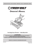
OPERATOR’S MANUAL
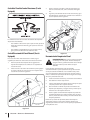
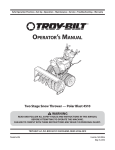
NOTE: Unit shown with optional
electric chute directional control
Two-Stage Snow Thrower — Storm 3090XP
WARNING
READ AND FOLLOW ALL SAFETY RULES AND INSTRUCTIONS IN THIS MANUAL
BEFORE ATTEMPTING TO OPERATE THIS MACHINE.
FAILURE TO COMPLY WITH THESE INSTRUCTIONS MAY RESULT IN PERSONAL INJURY.
TROY-BILT LLC, P.O. BOX 361131 CLEVELAND, OHIO 44136-0019
Printed In USA
Form No. 769-09004
(June 6, 2013)
1
To The Owner
Thank You
Thank you for purchasing a Troy-Bilt Snow Thrower. It was
carefully engineered to provide excellent performance when
properly operated and maintained.
in this manual may not be applicable to all models. We reserve
the right to change product specifications, designs and
equipment without notice and without incurring obligation.
Please read this entire manual prior to operating the equipment.
It instructs you how to safely and easily set up, operate and
maintain your machine. Please be sure that you, and any other
persons who will operate the machine, carefully follow the
recommended safety practices at all times. Failure to do so could
result in personal injury or property damage.
If applicable, the power testing information used to establish
the power rating of the engine equipped on this machine can be
found at www.opei.org or the engine manufacturer’s web site.
All information in this manual is relative to the most recent
product information available at the time of printing. Review
this manual frequently to familiarize yourself with the machine,
its features and operation. Please be aware that this Operator’s
Manual may cover a range of product specifications for various
models. Characteristics and features discussed and/or illustrated
If you have any problems or questions concerning the machine,
phone a authorized Troy-Bilt service dealer or contact us directly.
Troy-Bilt’s Customer Support telephone numbers, website
address and mailing address can be found on this page. We want
to ensure your complete satisfaction at all times.
Throughout this manual, all references to right and left side of the
machine are observed from the operating position.
Table of Contents
Safe Operation Practices ........................................ 3
Assembly & Set-Up .................................................. 7
Controls ...................................................................14
Operation ................................................................17
Maintenance & Adjustment .................................18
Service .....................................................................21
Troubleshooting .................................................... 23
Replacement Parts ................................................ 24
Attachments .......................................................... 25
Warranty ..................................................Back Cover
Record Product Information
MODEL NUMBER
Before setting up and operating your new equipment, please
locate the model plate on the equipment and record the
information in the provided area to the right. You can locate the
model plate by standing at the operator’s position and looking
down at the rear of the frame. This information will be necessary,
should you seek technical support via our web site, Customer
Support Department, or with a local authorized service dealer.
SERIAL NUMBER
Customer Support
Please do NOT return the machine to the retailer or dealer without first contacting the Customer Support Department.
If you have difficulty assembling this product or have any questions regarding the controls, operation, or maintenance of
this machine, you can seek help from the experts. Choose from the options below:
◊
Visit us on the web at www.troybilt.com
See How-to Maintenance and Parts Installation Videos at www.troybilt.com/tutorials
2
◊
Call a Customer Support Representative at (800) 828-5500 or (330) 558-7220
◊
8SJUFUP5SPZ#JMU--$t10#PYt$MFWFMBOE0)t
Important Safe Operation Practices
2
WARNING! This symbol points out important safety instructions which, if not followed,
could endanger the personal safety and/or property of yourself and others. Read and follow
all instructions in this manual before attempting to operate this machine. Failure to comply
with these instructions may result in personal injury.
When you see this symbol. HEED ITS WARNING!
CALIFORNIA PROPOSITION 65
WARNING! Engine Exhaust, some of its constituents, and certain vehicle components
contain or emit chemicals known to State of California to cause cancer and birth defects
or other reproductive harm.
DANGER: This machine was built to be operated according to the safe operation practices in
this manual. As with any type of power equipment, carelessness or error on the part of the
operator can result in serious injury. This machine is capable of amputating fingers, hands,
toes and feet and throwing foreign objects. Failure to observe the following safety
instructions could result in serious injury or death.
Training
Preparation
Read, understand, and follow all instructions on the
machine and in the manual(s) before attempting to
assemble and operate. Keep this manual in a safe place for
future and regular reference and for ordering replacement
parts.
Thoroughly inspect the area where the equipment is to be used.
Remove all doormats, newspapers, sleds, boards, wires and other
foreign objects, which could be tripped over or thrown by the
auger/impeller.
2.
Be familiar with all controls and their proper operation.
Know how to stop the machine and disengage them
quickly.
3.
Always wear safety glasses or eye shields during operation
and while performing an adjustment or repair to protect
your eyes. Thrown objects which ricochet can cause serious
injury to the eyes.
/FWFSBMMPXDIJMESFOVOEFSZFBSTPGBHFUPPQFSBUFUIJT
NBDIJOF$IJMESFOBOEPWFSTIPVMESFBEBOEVOEFSTUBOE
the instructions and safe operation practices in this manual
and on the machine and be trained and supervised by an
adult.
2.
Do not operate without wearing adequate winter outer
garments. Do not wear jewelry, long scarves or other loose
clothing, which could become entangled in moving parts.
Wear footwear which will improve footing on slippery
surfaces.
Never allow adults to operate this machine without proper
instruction.
3.
Use a grounded three-wire extension cord and receptacle
for all machines with electric start engines.
5.
Thrown objects can cause serious personal injury. Plan
your snow-throwing pattern to avoid discharge of material
toward roads, bystanders and the like.
Adjust auger housing height to clear gravel or crushed rock
surfaces.
5.
Disengage all control levers before starting the engine.
Keep bystanders, pets and children at least 75 feet from the
machine while it is in operation. Stop machine if anyone
enters the area.
Never attempt to make any adjustments while engine is
running, except where specifically recommended in the
operator’s manual.
7.
Exercise caution to avoid slipping or falling, especially
when operating in reverse.
7.
Let engine and machine adjust to outdoor temperature
before starting to clear snow.
3
Safe Handling of Gasoline
5.
To avoid personal injury or property damage use extreme care
in handling gasoline. Gasoline is extremely flammable and the
vapors are explosive. Serious personal injury can occur when
gasoline is spilled on yourself or your clothes which can ignite.
Wash your skin and change clothes immediately.
Never run an engine indoors or in a poorly ventilated area.
Engine exhaust contains carbon monoxide, an odorless
and deadly gas.
Do not operate machine while under the influence of
alcohol or drugs.
7.
Muffler and engine become hot and can cause a burn. Do
not touch. Keep children away.
a.
Use only an approved gasoline container.
b.
Extinguish all cigarettes, cigars, pipes and other
sources of ignition.
8.
Exercise extreme caution when operating on or crossing
gravel surfaces. Stay alert for hidden hazards or traffic.
c.
Never fuel machine indoors.
d.
Never remove gas cap or add fuel while the engine is
hot or running.
Exercise caution when changing direction and while
operating on slopes. Do not operate on steep slopes.
Plan your snow-throwing pattern to avoid discharge
towards windows, walls, cars etc. Thus, avoiding possible
property damage or personal injury caused by a ricochet.
Never direct discharge at children, bystanders and pets or
allow anyone in front of the machine.
Do not overload machine capacity by attempting to clear
snow at too fast of a rate.
Never operate this machine without good visibility or light.
Always be sure of your footing and keep a firm hold on the
handles. Walk, never run.
Disengage power to the auger/impeller when transporting
or not in use.
Allow machine to cool at least 5 minutes before
storing.
Never operate machine at high transport speeds on
slippery surfaces. Look down and behind and use care
when backing up.
Never fill containers inside a vehicle or on a truck
or trailer bed with a plastic liner. Always place
containers on the ground away from your vehicle
before filling.
If the machine should start to vibrate abnormally, stop
the engine, disconnect the spark plug wire and ground it
against the engine. Inspect thoroughly for damage. Repair
any damage before starting and operating.
If possible, remove gas-powered equipment from
the truck or trailer and refuel it on the ground. If this
is not possible, then refuel such equipment on a
trailer with a portable container, rather than from a
gasoline dispenser nozzle.
Disengage all control levers and stop engine before you
leave the operating position (behind the handles). Wait
until the auger/impeller comes to a complete stop before
unclogging the chute assembly, making any adjustments,
or inspections.
Never put your hand in the discharge or collector openings.
Always use the clean-out tool provided to unclog the
discharge opening. Do not unclog chute assembly while
engine is running. Shut off engine and remain behind
handles until all moving parts have stopped before
unclogging.
Use only attachments and accessories approved by the
manufacturer (e.g. wheel weights, tire chains, cabs etc.).
20.
When starting engine, pull cord slowly until resistance
is felt, then pull rapidly. Rapid retraction of starter cord
(kickback) will pull hand and arm toward engine faster than
you can let go. Broken bones, fractures, bruises or sprains
could result.
If situations occur which are not covered in this manual, use
care and good judgment. Contact Customer Support for
assistance and the name of your nearest servicing dealer.
e.
Allow engine to cool at least two minutes before
refueling.
f.
Never over fill fuel tank. Fill tank to no more than ½
inch below bottom of filler neck to provide space for
fuel expansion.
g.
Replace gasoline cap and tighten securely.
h.
If gasoline is spilled, wipe it off the engine and
equipment. Move machine to another area. Wait 5
minutes before starting the engine.
i.
Never store the machine or fuel container inside
where there is an open flame, spark or pilot light
(e.g. furnace, water heater, space heater, clothes
dryer etc.).
j.
k.
l.
m. Keep the nozzle in contact with the rim of the fuel
tank or container opening at all times until fueling is
complete. Do not use a nozzle lock-open device.
Operation
4
Do not put hands or feet near rotating parts, in the auger/
impeller housing or chute assembly. Contact with the
rotating parts can amputate hands and feet.
2.
The auger/impeller control lever is a safety device. Never
bypass its operation. Doing so makes the machine unsafe
and may cause personal injury.
3.
The control levers must operate easily in both directions
and automatically return to the disengaged position when
released.
Never operate with a missing or damaged chute assembly.
Keep all safety devices in place and working.
SECTION 2 — IMPORTANT SAFE OPERATION PRACTICES
Clearing a Clogged Discharge Chute
Hand contact with the rotating impeller inside the discharge
chute is the most common cause of injury associated with snow
throwers. Never use your hand to clean out the discharge chute.
To clear the chute:
SHUT THE ENGINE OFF!
2.
8BJUTFDPOETUPCFTVSFUIFJNQFMMFSCMBEFTIBWF
stopped rotating.
3.
Always use a clean-out tool, not your hands.
Maintenance & Storage
Never tamper with safety devices. Check their proper
operation regularly. Refer to the maintenance and
adjustment sections of this manual.
2.
Before cleaning, repairing, or inspecting machine
disengage all control levers and stop the engine. Wait until
the auger/impeller come to a complete stop. Disconnect
the spark plug wire and ground against the engine to
prevent unintended starting.
3.
Check bolts and screws for proper tightness at frequent
intervals to keep the machine in safe working condition.
Also, visually inspect machine for any damage.
Do not change the engine governor setting or over-speed
the engine. The governor controls the maximum safe
operating speed of the engine.
5.
Snow thrower shave plates and skid shoes are subject to
wear and damage. For your safety protection, frequently
check all components and replace with original equipment
manufacturer’s (OEM) parts only. “Use of parts which do
not meet the original equipment specifications may lead to
improper performance and compromise safety!”
Check control levers periodically to verify they engage
and disengage properly and adjust, if necessary. Refer
to the adjustment section in this operator’s manual for
instructions.
7.
Maintain or replace safety and instruction labels, as
necessary.
8.
Observe proper disposal laws and regulations for gas, oil,
etc. to protect the environment.
Prior to storing, run machine a few minutes to clear snow
from machine and prevent freeze up of auger/impeller.
Never store the machine or fuel container inside where
there is an open flame, spark or pilot light such as a water
heater, furnace, clothes dryer etc.
Always refer to the operator’s manual for proper
instructions on off-season storage.
Check fuel line, tank, cap, and fittings frequently for cracks
or leaks. Replace if necessary.
Do not crank engine with spark plug removed.
According to the Consumer Products Safety Commission
(CPSC) and the U.S. Environmental Protection Agency (EPA),
this product has an Average Useful Life of seven (7) years,
PSIPVSTPGPQFSBUJPO"UUIFFOEPGUIFAverage Useful
Life have the machine inspected annually by an authorized
service dealer to ensure that all mechanical and safety
systems are working properly and not worn excessively.
Failure to do so can result in accidents, injuries or death.
Do not modify engine
To avoid serious injury or death, do not modify engine in any
way. Tampering with the governor setting can lead to a runaway
engine and cause it to operate at unsafe speeds. Never tamper
with factory setting of engine governor.
Notice Regarding Emissions
Engines which are certified to comply with California and federal
EPA emission regulations for SORE (Small Off Road Equipment)
are certified to operate on regular unleaded gasoline, and
may include the following emission control systems: Engine
Modification (EM), Oxidizing Catalyst (OC), Secondary Air
Injection (SAI) and Three Way Catalyst (TWC) if so equipped.
Spark Arrestor
WARNING! This machine is equipped with an
internal combustion engine and should not be used
on or near any unimproved forest-covered, brush
covered or grass-covered land unless the engine’s
exhaust system is equipped with a spark arrestor
meeting applicable local or state laws (if any).
If a spark arrestor is used, it should be maintained in effective
working order by the operator. In the State of California the
BCPWFJTSFRVJSFECZMBX4FDUJPOPGUIF$BMJGPSOJB1VCMJD
Resources Code). Other states may have similar laws. Federal laws
apply on federal lands.
A spark arrestor for the muffler is available through your
nearest engine authorized service dealer or contact the service
EFQBSUNFOU10#PY$MFWFMBOE0IJP
SECTION 2 — IMPORTANT SAFE OPERATION PRACTICES
5
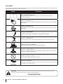
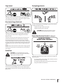
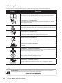
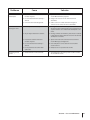
Safety Symbols
This page depicts and describes safety symbols that may appear on this product. Read, understand, and follow all instructions on the
machine before attempting to assemble and operate.
Symbol
Description
READ THE OPERATOR’S MANUAL(S)
Read, understand, and follow all instructions in the manual(s) before attempting to
assemble and operate
WARNING— ROTATING BLADES
Keep hands out of inlet and discharge openings while machine is running. There are rotating
blades inside
WARNING— ROTATING BLADES
Keep hands out of inlet and discharge openings while machine is running. There are rotating
blades inside
WARNING— ROTATING AUGER
Do not put hands or feet near rotating parts, in the auger/impeller housing or chute
assembly. Contact with the rotating parts can amputate hands and feet.
WARNING—THROWN OBJECTS
This machine may pick up and throw objects which can cause serious personal injury.
WARNING—GASOLINE IS FLAMMABLE
Allow the engine to cool at least two minutes before refueling.
WARNING— CARBON MONOXIDE
Never run an engine indoors or in a poorly ventilated area. Engine exhaust contains carbon
monoxide, an odorless and deadly gas.
WARNING— ELECTRICAL SHOCK
Do not use the engine’s electric starter in the rain
WARNING— HOT SURFACE
Engine parts, especially the muffler, become extremely hot during operation. Allow engine
and muffler to cool before touching.
WARNING! Your Responsibility—Restrict the use of this power machine to persons who read, understand and
follow the warnings and instructions in this manual and on the machine.
SAVE THESE INSTRUCTIONS!
6
SECTION 2 — IMPORTANT SAFE OPERATION PRACTICES
3
Assembly & Set-Up
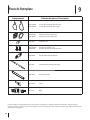
Contents of Carton
t
One Snow Thrower
t
Two Replacement Auger Shear Pins
t
One Chute Assembly
t
One Snow Thrower Operator’s
Manual
t
One Product Registration Card
t
One Chute Control Rod
t
One Engine Manual
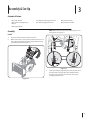
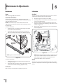
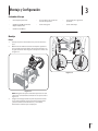
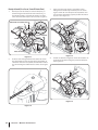
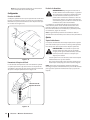
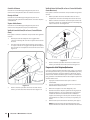
NOTE: Make certain the cables are seated properly in the
roller guides. See Figure 3-2.
Assembly
Handle
1MBDFUIFTIJGUMFWFSJOUIF'PSXBSEQPTJUJPO
2.
Observe the lower rear area of the snow thrower to be sure
both cables are aligned with roller guides before pivoting
UIFIBOEMFVQXBSE4FF'JHVSF
Figure 3-2
3.
Secure the handle by tightening the plastic knob located
on both the left and right sides of the handle. Remove
and discard any rubber bands, if present. They are for
packaging purposes only.
Figure 3-1
7
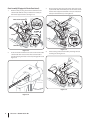
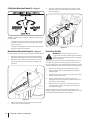
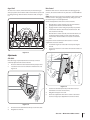
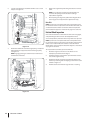
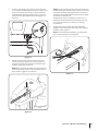
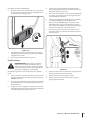
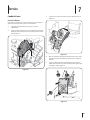
3.
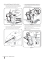
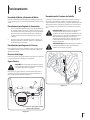
Chute Assembly (If Equipped w/ Electric Chute Control)
Remove cotter pin, wing nut and hex screw from chute
control head. Remove clevis pin and bow-tie cotter pin
from chute support bracket. See Figure 3-3.
Place chute onto chute base and ensure chute control rod
is positioned under the handle panel. Secure chute control
head to chute support bracket with clevis pin and bow-tie
DPUUFSQJOSFNPWFEJOTUFQ4FF'JHVSF
Chute Control Head
1
2
1
Chute Support
Bracket
Chute
Chute Base
Figure 3-5
Figure 3-3
2.
Insert the round end of the chute control rod into the chute
control head. Push rod as far into chute control head as
possible, keeping the holes in the rod pointing upward. See
'JHVSF
Finish securing chute control head by installing hex bolt
BOEXJOHOVU4FF'JHVSF
Figure 3-6
Figure 3-4
8
SECTION 3— ASSEMBLY & SET-UP
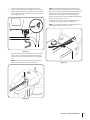
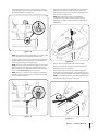
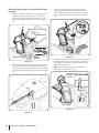
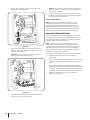
5.
NOTE: The hole furthest from the chute control head is
used to achieve further engagement of the chute control
rod into the coupler if required. Refer to the Maintenance &
Adjustments section for Chute Control Rod adjustment.
The hole closest to the chute control head is used for
manual movement of the chute assembly if required. Refer
to the Controls & Features section.
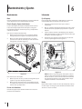
Insert the other end of the chute control rod into the
coupler below the handle panel. Make sure to line up the
flat end of the rod and the flat end of the coupler. You may
need to rotate the rod around until these two surfaces line
up. See Figure 3-7 inset.
7.
Check that the cables are properly routed through the
DBCMFHVJEFPOUPQPGUIFFOHJOF4FF'JHVSF
NOTE: For smoothest operation, the cables should all be to
the left of the chute directional control rod.
Figure 3-7
Push the chute control rod toward the control panel until
the hole in the rod lines up with the middle hole in the
chute control input and insert the cotter pin. See Figure
3-8.
NOTE: There is a reference hole provided at rear end of
control rod to help know when holes are vertical.
Figure 3-9
Figure 3-8
SECTION 3 — ASSEMBLY & SET-UP
9
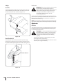
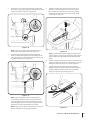
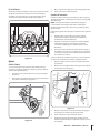
Chute Assembly (If Equipped w/ 4-Way Chute Control)
3.
Remove cotter pin, wing nut and hex screw from chute
control head. Remove clevis pin and bow-tie cotter pin
GSPNDIVUFTVQQPSUCSBDLFU4FF'JHVSF
Place chute onto chute base and ensure chute control
rod is positioned under the handle panel. Install hex bolt
previously removed, but do not secure with wing nut at
UIJTUJNF4FF'JHVSF
Chute Control Head
Chute Support
Bracket
Chute
Chute Base
Figure 3-12
Figure 3-10
2.
Insert chute control rod into chute control head. Push rod
as far into chute control head as possible, keeping the
IPMFTJOUIFSPEQPJOUJOHVQXBSE4FF'JHVSF
Squeeze the trigger on the joystick and rotate the chute by
hand to face forward. The holes in the chute control input
XJMMCFGBDJOHVQ4FF'JHVSF
NOTE: The chute will not rotate without squeezing the
trigger on the joystick.
Chute Control
Input
Figure 3-11
Figure 3-13
10
SECTION 3— ASSEMBLY & SET-UP
Top View
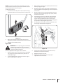
5.
Rotate the joystick to the one o’clock position so that the
silver indicator arrow on the pinion gear below the control
QBOFMGBDFTVQXBSE4FF'JHVSF
7.
Push the chute control rod toward the control panel until
the hole in the rod lines up with the hole in the chute
control input closest to the chute control head and insert
UIFDPUUFSQJO4FF'JHVSF
NOTE: The second hole is used to achieve further
engagement of the chute control rod into the pinion
gear if required. Refer to page 20 for Chute Control Rod
adjustments.
Figure 3-14
NOTE: The joystick will be angled slightly to the right at the
POFPDMPDLQPTJUJPO4FFi5PQ7JFXwJO'JHVSF
Insert the chute control rod into the pinion gear below the
joystick. Make sure to line up the hole in the rod with the
BSSPXPOUIFQJOJPOHFBS4FF'JHVSF
NOTE: The chute control rod will fit snuggly into the pinion
gear. Support the rear of the dash panel with one hand
while inserting the rod with your other hand to ensure the
rod is inserted all the way into the pinion gear.
NOTE: The hole is a reference for aligning the rod with the
indicator arrow on the pinion gear, and will be visible after
the rod has been inserted.
Figure 3-16
8.
Finish securing chute control head to chute support
bracket with wing nut, clevis pin, and bow-tie cotter pin
SFNPWFEJOTUFQ4FF'JHVSF
Check that the cables are properly routed through the
cable guide on top of the engine. Some models only have
POFDBCMFUPSPVUFUISPVHIUIFDBCMFHVJEF4FF'JHVSF
NOTE: For smoothest operation, the cables should all be to
the left of the chute directional control rod.
Figure 3-15
Figure 3-17
SECTION 3 — ASSEMBLY & SET-UP
11
Tire Pressure
Set-Up
WARNING: Under any circumstance do not exceed
manufacturer’s recommended psi. Equal tire
pressure should be maintained at all times. Excessive
pressure when seating beads may cause tire/rim
assembly to burst with force sufficient to cause
serious injury. Refer to side wall of tire for
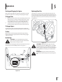
recommended pressure.
Shear Pins
A pair of replacement auger shear pins and bow tie cotter pins
are included with your snow thrower. Store them in your snow
UISPXFSTEBTIQBOFMVOUJMOFFEFE4FF'JHVSF
The tires are over-inflated for shipping purposes. Check the tire
pressure before operating the snow thrower. Refer to the tire side
wall for tire manufacturer’s recommended psi and deflate (or
inflate) the tires as necessary.
NOTE: If the tire pressure is not equal in both tires, the machine may
not travel in a straight path and the shave plate may wear unevenly.
Adjustments
Skid Shoes
The snow thrower skid shoes are adjusted upward at the factory
for shipping purposes. Adjust them downward, if desired, prior
to operating the snow thrower.
CAUTION: It is not recommended that you operate
this snow thrower on gravel as it can easily pick up
and throw loose gravel, causing personal injury or
damage to the snow thrower and surrounding
property.
Figure 3-18
t
For close snow removal on a smooth surface, raise skid
shoes higher on the auger housing.
t
Use a middle or lower position when the area to be cleared
is uneven, such as a gravel driveway.
Chute Clean-Out Tool
The chute clean-out tool is fastened to the top of the auger
housing with a mounting clip and a cable tie at the factory. Cut
UIFDBCMFUJFCFGPSFPQFSBUJOHUIFTOPXUISPXFS4FF'JHVSF
Chute Clean-Out Tool
Figure 3-19
12
SECTION 3— ASSEMBLY & SET-UP
NOTE: If you choose to operate the snow thrower on a gravel
surface, keep the skid shoes in position for maximum clearance
between the ground and the shave plate.
3.
While standing in the operator’s position (behind the snow
thrower), engage the auger.
Allow the auger to remain engaged for approximately ten
TFDPOETCFGPSFSFMFBTJOHUIFBVHFSDPOUSPM3FQFBUUIJT
several times.
5.
With the throttle control in the FAST (rabbit) position and
the auger control in the disengaged “up” position, walk to
the front of the machine.
Confirm that the auger has completely stopped rotating
and shows NO signs of motion. If the auger shows ANY
signs of rotating, immediately return to the operator’s
position and shut off the engine. Wait for ALL moving parts
to stop before re-adjusting the auger control.
7.
To readjust the control cable, loosen the upper hex screw
POUIFBVHFSDBCMFCSBDLFU4FF'JHVSF
8.
Position the bracket upward to provide more slack (or
downward to increase cable tension).
Retighten the upper hex screw.
3FQFBUTUFQTUISPVHIBCPWFUPWFSJGZQSPQFS
adjustment has been achieved.
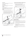
To adjust the skid shoes:
Loosen the four hex nuts (two on each side) and carriage
bolts. Move skid shoes to desired position. See Figure 3-20.
Figure 3-20
2.
Make certain the entire bottom surface of skid shoe is
against the ground to avoid uneven wear on the skid shoes.
3.
Retighten nuts and bolts securely.
Auger Control
WARNING! Prior to operating your snow thrower,
carefully read and follow all instructions below.
Perform all adjustments to verify your snow thrower
is operating safely and properly.
Check the adjustment of the auger control as follows:
2.
When the auger control is released and in the disengaged
“up” position, the cable should have very little slack. It
should NOT be tight.
In a well-ventilated area, start the snow thrower engine.
Refer to Engine Operator’s Manual.
Figure 3-21
SECTION 3 — ASSEMBLY & SET-UP
13
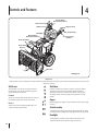
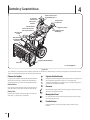
4
Controls and Features
Electric Chute
Directional Control †
Drive Control
Shift Lever
Auger Control
Heated Grips
Headlight
Manual Chute
Directional Control †
Steering Trigger
Control
Chute Assembly
Chute Clean
Out Tool
Skid Shoe
Augers
† If Equipped
Figure 4-1
Snow thrower controls and features are described below and illustrated in Figure 4-1 (Unit shown above with optional electric chute
directional control).
Shift Lever
Skid Shoes
The shift lever is located in the right side of the
handle panel and is used to determine ground
speed and direction of travel.
Forward
Position the skid shoes based on surface conditions. Adjust
upward for hard-packed snow. Adjust downward when
operating on gravel or crushed rock surfaces. See Set-Up &
Assembly section. Skid shoe styles and appearance vary by
model.
There are six forward (F) speeds. Position one (1) is
the slowest and position six (6) is the fastest.
Augers
Reverse
When engaged, the augers rotate and draw snow into the auger
housing.
There are two reverse (R) speeds. One (1) is the
slower and two (2) is the faster.
Chute Assembly
Snow drawn into the auger housing is discharged out the chute
assembly. Chute assembly styles and appearance vary by model.
Headlight
The headlight is located on top of the handle panel and is
automatically turned on when the engine is started.
14
Auger Control
Steering Trigger Controls
The auger control is located on the left handle. Squeeze the
control grip against the handle to engage the augers and start
snow throwing action. Release to stop.
Drive Control / Auger Clutch Lock
The left and right wheel steering trigger controls are located on
the underside of the handles.
t
Squeeze the right control to turn right.
t
Squeeze the left control to turn left.
CAUTION: Operate the snow thrower in open
areas until you are familiar with these controls.
The drive control is located on the right handle. Squeeze the
control grip against the handle to engage the wheel drive.
Release to stop.
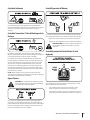
Electric Chute Directional Control (If so Equipped)
The drive control also locks the auger control so that you can
operate the chute directional control without interrupting
the snow throwing process. If the auger control is engaged
simultaneously with the drive control, the operator can release
the auger control (on the left handle) and the augers will remain
engaged. Release both controls to stop the augers and wheel
drive.
ELECTRIC CHUTE
DIRECTIONAL CONTROL
CHUTE TILT DOWN
CHUTE
ROTATE
LEFT
NOTE: Always release the drive control before changing speeds.
Failure to do so will result in increased wear on your machine’s
drive system.
CHUTE
ROTATE
RIGHT
Heated Grips
CHUTE TILT UP
CAUTION: It is recommended that you wear
gloves when using the heated grip. If the heated
grip becomes too hot, turn it off.
The electric chute directional control is located on the right side
of the dash panel.
t
To change the direction in which snow is thrown, move the
joy-stick to the right or to the left.
t
To change the angle/distance which snow is thrown, pivot
the joy-stick forward or backward.
To activate the heated grips, move the switch found on the rear
of the dash panel into the ON position. To turn off the heated
grips, move the switch found on the rear of the dash panel to the
OFF position.
SECTION 4 — CONTROLS AND FEATURES
15
4-Way Chute Directional Control (If so Equipped)
4.
Grasp the indented portion of the chute control rod and
manually rotate the chute assembly to the right or to the
left. See Figure 4-3.
The 4-way chute directional control is located on the left side of
the dash panel.
t
To change the direction in which snow is thrown, squeeze
the button on the joy-stick and pivot the joy-stick to the
right or to the left.
t
To change the angle/distance which snow is thrown, pivot
the joy-stick forward or backward.
Manual Chute Directional Control (If so Equipped)
Figure 4-3
Chute Clean-Out Tool
WARNING! Never use your hands to clear a
clogged chute assembly. Shut off engine and remain
behind handles until all moving parts have stopped
before unclogging.
Proceed as follows to utilize the manual chute directional control:
1.
Remove the cotter pin from either of the holes furthest
from the chute assembly on the chute rotation assembly.
2.
Push in the chute control rod until the hole in it lines up
with the third hole in the chute rotation assembly. See
Figure 4-2.
The chute clean-out tool is conveniently fastened to the rear of
the auger housing with a mounting clip. Should snow and ice
become lodged in the chute assembly during operation, proceed
as follows to safely clean the chute assembly and chute opening:
1.
Release both the Auger Control and the Drive Control.
2.
Stop the engine. Refer to the Engine Operator’s Manual.
Remove the key.
3.
Remove the clean-out tool from the clip which secures it to
the rear of the auger housing.
4.
Use the shovel-shaped end of the clean-out tool to
dislodge and scoop any snow and ice which has formed in
and near the chute assembly.
5.
Refasten the clean-out tool to the mounting clip on the
rear of the auger housing, reinsert the key and start the
snow thrower’s engine.
While standing in the operator’s position (behind the snow
thrower), engage the auger control for a few seconds to clear any
remaining snow and ice from the chute assembly.
Figure 4-2
3.
16
Reinsert the cotter pin through this hole and the chute
control rod as shown in Figure 4-2.
SECTION 4 — CONTROLS AND FEATURES
5
Operation
Starting and Stopping the Engine
Replacing Shear Pins
Refer to the Engine Operator’s Manual packed with your snow
thrower for instructions on starting and stopping the engine.
The augers are secured to the spiral shaft with shear pins and
bow-tie cotter pins. If the auger should strike a foreign object or
ice jam, the snow thrower is designed so that the pins may shear.
If the augers will not turn, check to see if the pins have sheared.
See Figure 5-2.
To Engage Drive
With the throttle control in the Fast (rabbit) position, move
shift lever into one of the six forward (F) positions or two
reverse (R) positions. Select a speed appropriate for the
snow conditions and a pace you’re comfortable with.
2.
Squeeze the drive control against the handle the snow
thrower will move. Release it and drive motion will stop.
To Engage Augers
To engage the augers and start throwing snow, squeeze the
auger control against the left handle. Release to stop the augers.
To Steer
With the drive control engaged, squeeze the right steering
trigger control to turn right. Squeeze the left steering trigger
control to turn left.
Heated Grips
CAUTION: It is recommended that you wear
gloves when using the heated grip. If the heated
grip becomes too hot, turn it off.
Figure 5-2
To activate the heated grips, move the switch found on the rear
PGUIFEBTIQBOFMJOUPUIF0/QPTJUJPO4FF'JHVSF
CAUTION: NEVER replace the auger shear pins
XJUIBOZUIJOHPUIFSUIBO0&.1BSU/P"
replacement shear pins. Any damage to the auger
gearbox or other components as a result of failing to
do so will NOT be covered by your snow thrower’s
warranty.
WARNING! Always turn off the snow thrower’s
engine and remove the key prior to replacing shear
pins.
Shown w/ optional electric chute control
Figure 5-1
17
6
Maintenance & Adjustments
Maintenance
Lubrication
Engine
Gear Shaft
Refer to the Engine Operator’s Manual.
The gear (hex) shaft should be lubricated at least once a season
or after every twenty-five (25) hours of operation.
Shave Plate and Skid Shoes
Allow the engine to run until it is out of fuel.
2.
Carefully pivot the snow thrower up and forward so that it
rests on the auger housing.
NOTE: Deluxe skid shoes (on select models) have two wear
FEHFT8IFOPOFTJEFXFBSTPVUUIFZDBOCFSPUBUFE¡UPVTF
the other edge.
3.
Remove the frame cover from the underside of the snow
thrower by removing the self-tapping screws which secure
it. Refer to Figure 7-3.
To remove skid shoes:
"QQMZBMJHIUDPBUJOHPGFOHJOFPJMPSJOPJM
UPUIFIFY
TIBGU4FF'JHVSF
The shave plate and skid shoes on the bottom of the snow
thrower are subject to wear. They should be checked periodically
and replaced when necessary.
Remove the four carriage bolts and hex flange nuts which
secure them to the snow thrower.
2.
Reassemble new skid shoes with the four carriage bolts
UXPPOFBDITJEF
BOEIFYGMBOHFOVUT3FGFSUP'JHVSF
Figure 6-2
NOTE: Augers not shown for clarity
Figure 6-1
To remove shave plate:
Remove the carriage bolts and hex nuts which attach it to
the auger housing.
2.
Reassemble new shave plate, making sure heads of carriage
bolts are to the inside of housing. Tighten securely.
Tire Pressure
3FGFSUPQBHFGPSJOGPSNBUJPOSFHBSEJOHUJSFQSFTTVSF
18
NOTE: When lubricating the hex shaft, be careful not to get
any oil on the aluminum drive plate or the rubber friction
wheel. Doing so will hinder the snow thrower’s drive
system. Wipe off any excess or spilled oil.
Wheels
At least once a season, remove both wheels. Clean and coat the
axles with a multipurpose automotive grease before reinstalling
wheels.
Auger Shaft
Drive Control
At least once a season, remove the shear pins from the auger
shaft. Spray lubricant inside the shaft and around the spacers and
the flange bearings found at either end of the shaft. See Figure
When the drive control is released and in the disengaged “up”
position, the cable should have very little slack. It should NOT be
tight.
NOTE: If excessive slack is present in the drive cable or if the snow
thrower’s drive is disengaging intermittently during operation,
the cable may be in need of adjustment.
Check the adjustment of the drive control as follows:
With the drive control released, push the snow thrower
gently forward. The unit should roll freely.
2.
Engage the drive control and gently attempt to push the
snow thrower forward. The wheels should not turn. The
unit should not roll freely.
3.
With the drive control released, move the shift lever back
BOEGPSUICFUXFFOUIF3QPTJUJPOBOEUIF'QPTJUJPO
several times. There should be no resistance in the shift
lever.
If any of the above tests failed, the drive cable is in need of
adjustment. Proceed as follows:
Shut off the engine as instructed in the separate engine
manual.
2.
Loosen the lower hex screw on the drive cable bracket. See
'JHVSF
Figure 6-3
Adjustments
Shift Cable
If the full range of speeds (forward and reverse) cannot be
achieved, adjust the shift cable as follows:
Place the shift lever in the fastest forward speed position.
2.
Loosen the hex nut on the shift cable index bracket. See
'JHVSF
Figure 6-5
3.
Position the bracket upward to provide more slack (or
downward to increase cable tension).
Retighten the upper hex screw.
5.
Check the adjustment of the drive control as described
above to verify proper adjustment has been achieved.
Figure 6-4
3.
Pivot the bracket downward to take up slack in the cable.
Retighten the hex nut.
SECTION 6 — MAINTENANCE & ADJUSTMENTS
19
Auger Control
Chute Directional Control (If Equipped w/ 4-Way Chute Control)
Refer to the Assembly and Set-up section for instructions on
adjusting the auger control cable.
To adjust the chute control rod, proceed as follows:
Remove the cotter pin from the hole closest to the chute
assembly on the chute rotation assembly.
2.
Pull out the chute control rod until the hole in it lines up
with the second hole in the chute rotation assembly. See
'JHVSF
3.
Reinsert the cotter pin through this hole and the chute
DPOUSPMSPE4FF'JHVSF
Chute Assembly
Refer to the Assembly and Set-up section for instructions on
adjusting the chute assembly.
Skid Shoes
Refer to the Assembly and Set-up section for instructions on
adjusting the skid shoes.
Chute Directional Control (If Equipped w/ Electric Chute
Control)
To adjust the chute control rod, proceed as follows:
Remove the cotter pin from either of the holes closest to
the chute assembly on the chute rotation assembly.
2.
Pull out the chute control rod until the hole in it lines up
with the hole furthest from the chute assembly on the
DIVUFSPUBUJPOBTTFNCMZ4FF'JHVSF
Figure 6-7
Off-Season Storage
If the snow thrower will not be used for 30 days or longer, follow
the storage instructions below.
Figure 6-6
3.
Reinsert the cotter pin through this hole and the chute
DPOUSPMSPE4FF'JHVSF
Run the engine until the fuel tank is empty and it stops due
to lack of fuel. Do not attempt to pour fuel from the engine.
2.
Lubricate the machine as instructed earlier in this section.
3.
Store in a clean, dry area.
If storing the snow thrower in an unventilated area,
rustproof the machine using a light oil or silicone to coat
the snow thrower.
5.
Clean the exterior of the engine and the snow thrower.
NOTE: Refer to the Engine Operator’s Manual for information on
storing your engine.
20
SECTION 6 — MAINTENANCE & ADJUSTMENTS
7
Service
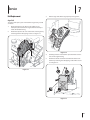
3.
Belt Replacement
Roll the auger belt off the engine pulley. See Figure 7-2.
Auger Belt
To remove and replace your snow thrower’s auger belt, proceed
as follows:
Allow the engine to run until it is out of fuel. Do not
attempt to pour fuel from the engine. Remove the key to
avoid unintended starting.
2.
Remove the plastic belt cover on the front of the engine by
SFNPWJOHUIFUXPTFMGUBQQJOHTDSFXT4FF'JHVSF
Figure 7-2
Carefully pivot the snow thrower up and forward so that it
rests on the auger housing.
5.
Remove the frame cover from the underside of the snow
thrower by removing the self-tapping screws which secure
it. See Figure 7-3.
Figure 7-1
Figure 7-3
21
Loosen and remove the shoulder bolt which acts as a belt
LFFQFS4FF'JHVSF
8.
Replace the auger belt by following instructions in reverse
order.
NOTE: Do not forget to reinstall the shoulder bolt and
reconnect the spring to the frame after installing a
replacement auger belt.
After replacing the auger belt, perform the Auger Control
UFTUPOQBHFUPWFSJGZUIFCFMUJTBEKVTUFEDPSSFDUMZ
Drive Belt
NOTE: Special tools are required and several components must
be removed in order to replace the snow thrower’s drive belt. See
an authorized Service Dealer to have the drive belt replaced or
phone Customer Support as instructed on page 2 for assistance.
Friction Wheel Inspection
If the snow thrower fails to drive with the drive control engaged,
and performing the drive control cable adjustment fails to
correct the problem, the friction wheel may need to be replaced.
Figure 7-4
7.
Remove the belt from around the auger pulley, and slip the
belt between the support bracket and the auger pulley.
See Figure 7-5.
NOTE: Engaging the auger control will ease removal and
reinstallation of the belt.
Figure 7-5
22
SECTION 7— SERVICE
NOTE: Special tools are required and several components must
be removed in order to replace the snow thrower’s friction wheel
rubber. See an authorized Service Dealer to have the friction
wheel rubber replaced or phone Customer Support as instructed
on page 2 for assistance.
To inspect the friction wheel, proceed as follows:
Allow the engine to run until it is out of fuel. Do not
attempt to pour fuel from the engine.
2.
Carefully pivot the snow thrower up and forward so that it
rests on the auger housing.
3.
Remove the frame cover from the underside of the snow
thrower by removing four self-tapping screws which secure
it. Refer to Figure 7-3.
Examine the friction wheel for signs of wear or cracking.
8
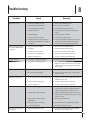
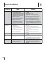
Troubleshooting
Problem
Cause
Remedy
Choke not in CHOKE position.
Move choke to CHOKE position.
2. Spark plug wire disconnected.
2. Connect wire to spark plug.
3. Fuel tank empty or stale fuel.
3. Fill tank with clean, fresh gasoline.
Engine not primed.
Prime engine as instructed in the Operation
section.
5. Faulty spark plug.
5. Clean, adjust gap, or replace.
Key not in ignition on engine.
Insert key fully into the switch.
7. Extension cord not connected (when
using electric start button, on models so
equipped).
7. Connect one end of the extension cord to the
electric starter outlet and the other end to a
UISFFQSPOHWPMUHSPVOEFE"$PVUMFU
Engine running on CHOKE.
Move choke lever to RUN position.
2. Stale fuel.
2. Fill tank with clean, fresh gasoline.
3. Water or dirt in fuel system.
3. Drain fuel tank. Refill with fresh fuel.
Carburetor out of adjustment.
Contact an authorized Service Center.
5. Engine over-governed.
5. Contact an authorized Service Center.
Engine overheats
Carburetor not adjusted properly.
Contact an authorized Service Center.
Excessive vibration
Loose parts or damaged auger.
Stop engine immediately and disconnect spark
plug wire. Tighten all bolts and nuts. If vibration
continues, have unit serviced by an authorized
Service Center.
Loss of power
Spark plug wire loose.
Connect and tighten spark plug wire.
2. Gas cap vent hole plugged.
2. Remove ice and snow from gas cap. Be certain
vent hole is clear.
Drive control cable in need of adjustment.
Adjust drive control cable. Refer to Maintenance
& Adjustments section.
2. Drive belt loose or damaged.
2. Contact an authorized Service Center.
3. Friction wheel worn.
3. Contact an authorized Service Center.
Chute assembly clogged.
Stop engine immediately and disconnect spark
plug wire. Clean chute assembly and inside of
auger housing with clean-out tool or a stick.
2. Foreign object lodged in auger.
2. Stop engine immediately and disconnect spark
plug wire. Remove object from auger with cleanout tool or a stick.
3. Auger control cable in need of
adjustment.
3. Refer to Auger Control Test.
Auger belt loose or damaged.
Refer to Maintenance & Adjustments section.
5. Shear pin(s) sheared.
5. Replace with new shear pin(s).
Chute assembled incorrectly.
Disassemble chute control and reassemble as
directed in the Assembly section.
Engine fails to start
Engine running erratically/
inconsistent RPM (hunting
or surging)
Unit fails to propel itself
Unit fails to discharge snow
Chute fails to easily rotate
EFHSFFT
23
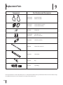
9
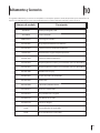
Replacement Parts
Component
Part Number and Description
954-04195A
954-04201A
Auger Drive Belt
Wheel Drive Belt
684-04153C
935-04054
Friction Wheel Assembly
Friction Wheel Rubber
925-1629
Lamp, 12V
738-04124A
714-04040
Shear Pin, 1.50
Bow-tie Cotter Pin
790-00091
Slide Shoe, Deluxe
931-2643
Chute Clean-out Tool
790-00119
Shave Plate
951-10630
Key
951-10292
Spark Plug
Phone (800) 828-5500 to order replacement parts or a complete Parts Manual (have your full model number and serial number ready).
Parts Manual downloads are also available free of charge at www.troybilt.com.
24
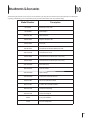
10
Attachments & Accessories
The following attachments and accessories are available for your Troy-Bilt snow thrower. Phone (800) 828-5500 for information
regarding compatibility, price and availability (have your full model number and serial number ready).
Model Number
Description
929-0071A
Extension Cord, 110V
753-05762A
Heated Grips
OEM-390-679
Drift Cutter Kit
490-241-0010
Polymer Skid Shoe Kit
490-241-0032
Snow Cab
490-241-Y014
Troy-Bilt Snow Thrower Maintenance Kit
490-290-0010
Snow Thrower Cover
490-241-0028
Snow Thrower Tire Chains (16” x 4.8” Tires)
490-241-0029
Snow Thrower Tire Chains (16” x 6.5” Tires)
490-900-0062
Non-Stick Spray
490-240-0011
Fuel Test Swabs
490-850-0008
Siphon Pump
490-000-0028
Carburetor and Choke Cleaner
490-325-L019
24 oz. Tire and Tube Sealant
490-325-L021
1 Gallon Tire and Tube Sealant
490-850-L013
Tire/Tube Foot Pump
490-850-L014
Deluxe Tire Plug Kit
22208
8 oz. Fuel Stabilizer
22216
32 oz. Fuel Stabilizer
25
MANUFACTURER’S LIMITED WARRANTY FOR
The limited warranty set forth below is given by Troy-Bilt LLC with
respect to new merchandise purchased and used in the United
States and/or its territories and possessions, and by MTD Products
Limited with respect to new merchandise purchased and used
in Canada and/or its territories and possessions (either entity
respectively, “Troy-Bilt”).
b.
Routine maintenance items such as lubricants, filters, blade
sharpening, tune-ups, brake adjustments, clutch adjustments,
deck adjustments, and normal deterioration of the exterior
finish due to use or exposure.
c.
Service completed by someone other than an authorized
service dealer.
This warranty is in addition to any applicable emissions warranty
provided with your product.
d.
Troy-Bilt does not extend any warranty for products sold or
exported outside of the United States and/or Canada, and
their respective possessions and territories, except those sold
through Troy-Bilt’s authorized channels of export distribution.
e.
Replacement parts that are not genuine Troy-Bilt parts.
f.
Transportation charges and service calls.
g.
Troy-Bilt does not warrant this product for commercial use.
“Troy-Bilt” warrants this product (excluding its Normal Wear Parts
and Attachments as described below) against defects in material
and workmanship for a period of three (3) years commencing
on the date of original purchase and will, at its option, repair or
replace, free of charge, any part found to be defective in materials
or workmanship. This limited warranty shall only apply if this
product has been operated and maintained in accordance with
the Operator’s Manual furnished with the product, and has not
been subject to misuse, abuse, commercial use, neglect, accident,
improper maintenance, alteration, vandalism, theft, fire, water,
or damage because of other peril or natural disaster. Damage
resulting from the installation or use of any part, accessory or
attachment not approved by Troy-Bilt for use with the product(s)
covered by this manual will void your warranty as to any resulting
damage.
Normal Wear Parts are warranted to be free from defects in material
and workmanship for a period of thirty (30) days from the date of
purchase. Normal wear parts include, but are not limited to items
such as: batteries, belts, blades, blade adapters, tines, grass bags,
wheels, rider deck wheels, seats, snow thrower skid shoes, friction
wheels, shave plates, auger spiral rubber and tires.
Attachments — Troy-Bilt warrants attachments for this product
against defects in material and workmanship for a period of one
ZFBSDPNNFODJOHPOUIFEBUFPGUIFBUUBDINFOUTPSJHJOBM
purchase or lease. Attachments include, but are not limited to items
such as: grass collectors and mulch kits.
HOW TO OBTAIN SERVICE: Warranty service is available, WITH
PROOF OF PURCHASE, through your local authorized service dealer.
To locate the dealer in your area:
In the U.S.A.
$IFDLZPVS:FMMPX1BHFTPSDPOUBDU5SPZ#JMU--$BU10#PY
$MFWFMBOE0IJPPSDBMM
PSMPHPOUPPVS8FCTJUFBUXXXUSPZCJMUDPN
In Canada
$POUBDU.5%1SPEVDUT-JNJUFE,JUDIFOFS0//(+PSDBMM
PSMPHPOUPPVS8FCTJUFBUXXXNUEDBOBEBDPN
This limited warranty does not provide coverage in the following
cases:
a.
Log splitter pumps, valves, and cylinders have a separate
one- year warranty.
No implied warranty, including any implied warranty of
merchantability or fitness for a particular purpose, applies
after the applicable period of express written warranty above
as to the parts as identified. No other express warranty,
whether written or oral, except as mentioned above, given
by any person or entity, including a dealer or retailer, with
respect to any product, shall bind Troy-Bilt. During the period
of the warranty, the exclusive remedy is repair or replacement
of the product as set forth above.
The provisions as set forth in this warranty provide the sole
and exclusive remedy arising from the sale. Troy-Bilt shall
not be liable for incidental or consequential loss or damage
including, without limitation, expenses incurred for substitute
or replacement lawn care services or for rental expenses to
temporarily replace a warranted product.
Some states do not allow the exclusion or limitation of incidental
or consequential damages, or limitations on how long an implied
warranty lasts, so the above exclusions or limitations may not apply
to you.
In no event shall recovery of any kind be greater than the amount
of the purchase price of the product sold. Alteration of safety
features of the product shall void this warranty. You assume the
risk and liability for loss, damage, or injury to you and your property
and/or to others and their property arising out of the misuse or
inability to use the product.
This limited warranty shall not extend to anyone other than the
original purchaser or to the person for whom it was purchased as a
gift.
HOW STATE LAW RELATES TO THIS WARRANTY: This limited
warranty gives you specific legal rights, and you may also have
other rights which vary from state to state.
IMPORTANT: Owner must present Original Proof of Purchase to
obtain warranty coverage.
Troy-Bilt LLC, P.O. BOX 361131 CLEVELAND, OHIO 44136-0019; Phone: 1-866-840-6483, 1-330-558-7220
MTD Canada Limited - KITCHENER, ON N2G 4J1; Phone 1-800-668-1238
023434 REV. A
.FEJEBTJNQPSUBOUFTEFTFHVSJEBEt$POöHVSBDJØOt'VODJPOBNJFOUPt.BOUFOJNJFOUPt4FSWJDJPt
4PMVDJØOEFQSPCMFNBTt(BSBOUÓB
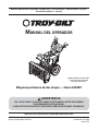
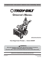
MANUAL DEL OPERADOR
/05"6OJEBEEFNVFTUSBBSSJCB
DPOFMDPOUSPMEJSFDDJPOBMEFM
DBOBMPQDJPOBMFMÏDUSJDB
.ÈRVJOBRVJUBOJFWFEFEPTFUBQBT4UPSN91
"%7&35&/$*"
-&":4*("50%"4-"4*/4536$$*0/&4%&&45&."/6"-"/5&4%&10/&3&/
'6/$*0/".*&/50&45".«26*/"
4*/03&41&5"&45"4*/4536$$*0/&416&%&13070$"3-&4*0/&41&340/"-&4
TROY-BILT LLC, P.O. BOX 361131 CLEVELAND, OHIO 44136-0019
Impreso en Estados Unidos de América
Formulario No. 769-09004
(Juno 6, 2013)
1
Al propietario
Gracias
Gracias por comprar una Troy-Bilt máquina quitanieve. La
misma ha sido diseñada cuidadosamente para brindar excelente
rendimiento si se la opera y mantiene correctamente.
las especificaciones de los productos, los diseños y el equipo
estándar sin previo aviso y sin generar responsabilidad por
obligaciones de ningún tipo.
Por favor lea todo este manual antes de operar el equipo.
Le indica cómo configurar, operar y mantener la máquina
con seguridad y fácilmente. Por favor asegúrese de seguir
cuidadosamente y en todo momento las prácticas de seguridad
recomendadas, y hacérselas seguir a cualquier otra persona que
opere la máquina. En caso de no hacerlo podrían producirse
lesiones personales o daños materiales.
En su caso, los datos de prueba de potencia utilizados para
establecer la máxima potencia equipado en esta máquina se
pueden encontrar en www.opei.org o sitio web del fabricante del
motor.
Toda la información contenida en este manual hace referencia
a la más reciente información de producto disponible en el
momento de la impresión. Revise el manual frecuentemente
para familiarizarse con la unidad, sus características y
funcionamiento. Por favor tenga en cuenta que este Manual
del Operador puede cubrir una gama de especificaciones de
productos de diferentes modelos. Las características y funciones
incluidas y/o ilustradas en este manual pueden no ser aplicables
a todos los modelos. Reservamos el derecho de modificar
Si tiene algún problema o duda respecto a la unidad, llame a
un distribuidor de servicio Troy-Bilt autorizado o póngase en
contacto directamente con nosotros. Los números de teléfono,
dirección del sitio web y dirección postal de la Asistencia al
Cliente de Troy-Bilt se encuentran en esta página. Queremos
garantizar su entera satisfacción en todo momento.
En este manual, las referencias al lado derecho o izquierdo de la
máquina se observan desde la posición del operador.
Índice
Importante Medidas importantes de seguridad 29
Ensamblado y Configuración............................... 33
Controles y Características ................................... 40
Funcionamiento .................................................... 43
Mantenimiento y Ajustes...................................... 44
Servicio ................................................................... 47
Solución de Problemas ......................................... 50
Piezas de Reemplazo ............................................ 52
Accesorios .............................................................. 53
Garantía ...................................... Cubierta posterior
Registro de información de producto
NÚMERO DE MODELO
Antes de configurar y operar su equipo nuevo, por favor localice
la placa del modelo en el equipo y registre la información en
el área situada a la derecha. Para encontrar la placa de modelo,
colóquese detrás de la unidad en la posición del operador y mire
hacia la parte inferior de la sección trasera del chasis. Si tiene
que solicitar soporte técnico a través de nuestro sitio web, el
Departamento de Asistencia al Cliente, o de un distribuidor de
servicio autorizado local, necesitará esta información.
NÚMERO DE SERIE
Asistencia al Cliente
Por favor, NO devuelva la unidad al minorista o distribuidor sin ponerse en contacto primero con el Departamento de
Asistencia al Cliente.
En caso de tener problemas para montar este producto o de tener dudas con respecto a los controles, funcionamiento o
mantenimiento del mismo, puede solicitar la ayuda de expertos. Elija entre las opciones que se presentan a continuación:
◊
Visite nuestro sitio web en www.troybilt.com
Ver Vídeos demostrativos de instalación de mantenimiento y piezas en www.troybilt.com/Tutorials
28
◊
Llame a un representante de Asistencia al Cliente al (800) 828-5500 ó (330) 558-7220
◊
&TDSÓCBOPTB5SPZ#JMU--$t10#PYt$MFWFMBOE0)t
Medidas Importantes de Seguridad
2
¡ADVERTENCIA! La presencia de este símbolo indica que se trata de instrucciones
importantes de seguridad que se deben respetar para evitar poner en peligro su seguridad
personal y/o material y la de otras personas. Lea y siga todas las instrucciones de este manual
antes de poner en funcionamiento esta máquina. Si no respeta estas instrucciones puede
provocar lesiones personales.
Cuando vea este símbolo. ¡TENGA EN CUENTAS LAS ADVERTENCIAS!
PROPOSICIÓN 65 DE CALIFORNIA
¡ADVERTENCIA! El escape del motor de este producto, algunos de sus componentes y
algunos componentes del vehículo contienen o liberan sustancias químicas que el estado
de California considera que pueden producir cáncer, defectos de nacimiento u otros
problemas reproductivos.
PELIGRO: Esta máquina está diseñada para ser utilizada respetando las normas de
seguridad contenidas en este manual. Al igual que con cualquier tipo de equipo motorizado,
un descuido o error por parte del operador puede producir lesiones graves. Esta máquina es
capaz de amputar dedos, manos y pies y de arrojar objetos extraños con gran fuerza. De no
respetar las instrucciones de seguridad siguientes se pueden producir lesiones graves o la
muerte.
Capacitación
Lea, entienda y cumpla todas las instrucciones incluidas en
la máquina y en los manuales antes de montarla y utilizarla.
Guarde este manual en un lugar seguro para consultas
futuras y periódicas, así como para solicitar repuestos.
2.
Familiarícese con todos los controles y con el uso adecuado
de los mismos. Sepa cómo detener la máquina y desactivar
los controles rápidamente.
3.
/PQFSNJUBOVODBRVFMPTOJ×PTNFOPSFTEFB×PT
VUJMJDFOFTUBNÈRVJOB-PTOJ×PTEFB×PTFOBEFMBOUF
deben leer y entender las instrucciones de operación y
normas de seguridad contenidas en este manual, y en la
máquina ydeben ser entrenados y supervisados por un
adulto.
Nunca permita que los adultos operen esta máquina sin
recibir antes la instrucción apropiada.
5.
Los objetos arrojados por la máquina pueden producir
lesiones graves. Planifique el patrón en el que va a ir
arrojando nieve para evitar que la descarga de material se
realice hacia los caminos, los observadores, etc.
Mantenga a los observadores, ayudantes, mascotas y niños
por lo menos a 75 pies de la máquina mientras la misma
está en funcionamiento. Detenga la máquina si alguien se
acerca.
7.
Sea precavido para evitar patinarse o caerse especialmente
cuando opera la máquina en reversa.
Preparativos
Inspeccione minuciosamente el área donde utilizará el equipo.
Saque todos los felpudos, periódicos, trineos, tablas, cables y
otros objetos extraños con los que podría tropezar o que podrían
ser arrojados por la barrena / impulsor.
Para protegerse los ojos utilice siempre anteojos o
antiparras de seguridad mientras opera la máquina o
mientras la ajusta o repara. Los objetos arrojados que
rebotan pueden producir lesiones oculares graves.
2.
No opere la máquina sin la vestimenta adecuada para
estar al aire libre en invierno. No utilice alhajas, bufandas
largas u otras prendas sueltas que podrían enredarse en las
partes móviles. Utilice un calzado especial para superficies
resbaladizas.
3.
Use un prolongador y un tomacorriente de tres cables con
conexión a tierra para todas las máquinas con motores de
encendido eléctrico.
Ajuste la altura de la caja del tomacorriente para limpiar la
grava o las superficies con piedras trituradas.
5.
Desengrane todas las palancas de control antes de arrancar
el motor.
29
Nunca intente realizar ajustes mientras el motor está
en marcha excepto en los casos específicamente
recomendados en el manual del operador.
7.
Deje que el motor y la máquina se adapten a la
temperatura exterior antes de comenzar a sacar la nieve.
Manejo seguro de la gasolina
Para evitar lesiones personales o daños materiales tenga mucho
cuidado cuando trabaje con gasolina. La gasolina es sumamente
inflamable y sus vapores pueden causar explosiones. Si se
derrama gasolina encima o sobre la ropa se puede lesionar
gravemente ya que se puede incendiar. Lávese la piel y cámbiese
de ropa de inmediato.
a.
b.
Utilice sólo los recipientes para gasolina autorizados.
Apague todos los cigarrillos, cigarros, pipas y otras
fuentes de combustión.
c. Nunca cargue combustible en la máquina en un
espacio cerrado.
d. Nunca saque la tapa del combustible ni agregue
combustible mientras el motor está caliente o en
marcha.
e. Deje que el motor se enfríe por lo menos dos
minutos antes de volver a cargar combustible.
f.
Nunca llene en exceso el depósito de combustible.
Llene el tanque a no más de ½ pulgada por debajo
de la base del cuello de llenado dejando espacio
para la dilatación del combustible.
g. Vuelva a colocar la tapa de la gasolina y ajústela
bien.
h. Limpie el combustible que se haya derramado sobre
el motor y el equipo. Traslade la máquina a otra
zona. Espere 5 minutos antes de encender el motor.
i.
Nunca almacene la máquina o el recipiente de
combustible en un espacio cerrado donde haya
fuego, chispas o luz piloto (por ejemplo, hornos,
calentadores de agua, calefactores, secadores de
ropa, etc.).
j.
Deje que la máquina se enfríe por lo menos 5
minutos antes de guardarla.
k. Nunca llene los recipientes en el interior de
un vehículo o camión o caja de remolque con
recubrimientos plásticos. Coloque siempre los
recipientes en el piso y lejos del vehículo antes de
llenarlos.
l.
Si es posible, retire el equipo a gasolina del camión o
remolque y llénelo en el suelo. Si esto no es posible,
llene el equipo en un remolque con contenedor
portátil, en vez de desde una boquilla dispensadora
de gasolina.
m. Mantenga la boquilla dispensadora en contacto
con el borde del depósito de combustible o con la
abertura del recipiente en todo momento, hasta
terminar la carga. No utilice un dispositivo de
apertura/cierre de boquilla.
2.
3.
5.
7.
8.
Funcionamiento
30
No ponga las manos o los pies cerca de las piezas
rotatorias, en la caja de la barrena / impulsor o en el
montaje del canal de descarga. Hacer contacto con piezas
giratorias puede resultar en la amputación de manos o
pies.
SECTION 2 — MEDIDAS IMPORTANTES DE SEGURIDAD
La palanca de control de la barrena / impulsor es un
dispositivo de seguridad. Nunca evite su funcionamiento.
De hacerlo la operación de la máquina es riesgosa y puede
ocasionar lesiones.
Las palancas de control deben funcionar bien en ambas
direcciones y regresar automáticamente a la posición de
desengrane cuando se las suelta.
Nunca opere la máquina si falta un montaje del canal o si
el mismo está dañado. Mantenga todos los dispositivos de
seguridad en su lugar y en funcionamiento.
Nunca encienda el motor en espacios cerrados o en una
zona con poca ventilación. El escape del motor contiene
monóxido de carbono, un gas inodoro y letal.
No utilice la máquina bajo la influencia del alcohol o las
drogas.
El silenciador y el motor se calientan y pueden causar
quemaduras. No los toque. Mantenga a los niños alejados.
Sea sumamente precavido cuando opere la máquina sobre
una superficie con grava o cuando la cruce. Manténgase
alerta por si se presentan peligros ocultos o tránsito.
Tenga cuidado cuando cambie de dirección o cuando
opere la máquina en pendientes. No use la máquina en
pendientes pronunciadas.
Planifique el patrón en el que va a ir arrojando nieve para
evitar que la descarga de material se produzca hacia las
ventanas, las paredes, los automóviles, etc. y evitar así
posibles daños materiales o lesiones producidas por los
rebotes.
Nunca dirija la descarga hacia los niños, los observadores
o las mascotas ni deje que nadie se pare delante de la
máquina.
No sobrecargue la capacidad de la máquina tratando de
sacar la nieve muy rápidamente.
Nunca opere esta máquina sin buena visibilidad o
iluminación. Siempre debe estar seguro de que está bien
afirmado y sujetando firmemente las manijas. Camine,
nunca corra.
Corte la corriente a la barrena / impulsor cuando transporte
la máquina o cuando la misma no está en uso.
Nunca opere la máquina a alta velocidad de
desplazamiento sobre superficies resbaladizas. Mire hacia
abajo y hacia atrás y tenga cuidado cuando vaya marcha
atrás.
Si la máquina comenzara a vibrar de manera anormal,
detenga el motor, desconecte el cable de la bujía y póngala
de manera que haga masa contra el motor. Inspeccione la
máquina minuciosamente para ver si está dañada. Repare
todos los daños antes de encender y operar la máquina.
Desengrane todas las palancas de control y detenga el
motor antes de dejar la posición de operación (detrás de las
manijas). Espere a que la barrena / impulsor se detenga por
completo antes de destapar el montaje del canal o realizar
ajustes e inspecciones.
Nunca ponga las manos en las aberturas de descarga o
de recolección. Utilice siempre la herramienta de limpieza
que se adjunta para destapar la abertura de descarga. No
destape el montaje del canal mientras el motor está en
funcionamiento. Antes de destaparlo, apague el motor
y permanezca detrás de las manijas hasta que todas las
partes móviles se hayan detenido.
Use sólo uniones y accesorios aprobados por el fabricante
(por ejemplo, pesas para las ruedas, cadenas para los
neumáticos, cabinas, etc.).
20.
Para encender el motor, jale de la cuerda lentamente hasta
que sienta resistencia, luego jale rápidamente. El repliegue
rápido de la cuerda de arranque (tensión de retroceso) le
jalará la mano y el brazo hacia el motor más rápido de lo
que usted puede soltar. El resultado pueden ser huesos
rotos, fracturas, hematomas o esguinces.
Si se presentan situaciones que no están previstas en este
manual, sea cuidadoso y use el sentido común. Póngase en
contacto con Asistencia al Cliente para solicitar ayuda y el
nombre del distribuidor de servicio más cercano.
Mantenimiento y Almacenamiento
Nunca altere los dispositivos de seguridad. Controle
periódicamente que funcionen correctamente. Remítase a
las secciones de mantenimiento y ajuste de este manual.
2.
Antes de realizar la limpieza, reparar o revisar la máquina,
desengrane todas las palancas de control y detenga el
motor. Espere a que la barrena / impulsor se detenga
por completo. Desconecte el cable de la bujía y póngalo
haciendo masa contra el motor para evitar que se encienda
accidentalmente.
3.
Controle frecuentemente que todos los pernos y tornillos
estén bien ajustados para comprobar que la máquina se
encuentra en condiciones seguras de funcionamiento.
Además, haga una inspección visual de la máquina para
verificar si está dañada.
No cambie la configuración del regulador del motor
ni acelere demasiado el mismo. El regulador del motor
controla la velocidad máxima segura de funcionamiento
del motor.
5.
Las placas de raspado y las zapatas antideslizantes que se
usan con la máquina quitanieve se desgastan y se dañan.
Para proteger su seguridad, verifique frecuentemente
todos los componentes y reemplácelos sólo con partes
de los fabricantes de equipos originales (OEM). “¡El uso de
piezas que no cumplen con las especificaciones del equipo
original puede resultar en rendimiento inadecuado además
de poner en riesgo la seguridad!”
Revise las palancas de control periódicamente para
verificar que engranen y desengranen adecuadamente y
ajústelos si es necesario. Consulte la sección de ajustes de
este manual del operador para obtener instrucciones.
7.
Mantenga o reemplace las etiquetas de seguridad e
instrucciones según sea necesario.
8.
Respete las normas referentes a la disposición correcta y las
reglamentaciones sobre gasolina, aceite, etc. para proteger
el medio ambiente.
Antes de almacenar la máquina enciéndala unos minutos
para sacar la nieve que haya quedado en la misma y para
evitar así que se congele la barrena / impulsor.
Nunca almacene la máquina o el recipiente de combustible
en un espacio cerrado donde haya fuego, chispas o luz
piloto como por ejemplo, calentadores de agua, hornos,
secadores de ropa, etc.
Consulte siempre el manual del operador para obtener
instrucciones adecuadas para el almacenamiento fuera de
temporada.
Verifique frecuentemente la línea de combustible, el
tanque, el tapón, y los accesorios buscando rajaduras o
pérdidas. Reemplace de ser necesario.
No dé arranque al motor si no está la bujía de encendido.
Según la Comisión de Seguridad de Productos para el
Consumidor de los Estados Unidos (CPSC) y la Agencia
de Protección Ambiental de los Estados Unidos (EPA),
este producto tiene una vida útil media de siete (7) años,
ØIPSBTEFGVODJPOBNJFOUP"MGJOBMJ[BSMBvida útil
media, adquiera una máquina nueva o haga inspeccionar
anualmente ésta por un distribuidor de servicio autorizado
para cerciorarse de que todos los sistemas mecánicos y de
seguridad funcionan correctamente y no tienen excesivo
desgaste. Si no lo hace, pueden producirse accidentes,
lesiones o muerte
No modifique el motor
Para evitar lesiones graves o la muerte, no modifique el motor
bajo ninguna circunstancia. Si cambia la configuración del
regulador el motor puede descontrolarse y operar a velocidades
inseguras. Nunca cambie la configuración de fábrica del
regulador del motor.
Aviso referido a emisiones
Los motores que están certificados y cumplen con las
regulaciones de emisiones federales EPA y de California para
SORE (Equipos pequeños todo terreno) están certificados para
operar con gasolina común sin plomo y pueden incluir los
siguientes sistemas de control de emisiones: Modificación de
motor (EM) y catalizador de tres vías (TWC) si están equipados de
esa manera.
Guardachispas
¡ADVERTENCIA! Esta máquina está equipada con
un motor de combustión interna y no debe ser
utilizada en o cerca de un terreno agreste cubierto
por bosque, malezas o hierba excepto si el sistema
de escape del motor está equipado con un
amortiguador de chispas que cumpla con las leyes
locales o estatales correspondientes, en caso de
haberlas.
Si se utiliza un amortiguador de chispas el operador lo debe
mantener en condiciones de uso adecuadas. En el Estado
de California las medidas anteriormente mencionadas son
FYJHJEBTQPSMFZ"SUÓDVMPEFM$ØEJHPEF3FDVSTPT1ÞCMJDPT
de California). Es posible que existan leyes similares en otros
estados. Las leyes federales se aplican en territorios federales.
Puede conseguir el amortiguador de chispas para el silenciador
a través de su distribuidor autorizado de motores o poniéndose
FODPOUBDUPDPOFMEFQBSUBNFOUPEFTFSWJDJPT10#PY
$MFWFMBOE0IJP
SECTION 2 — MEDIDAS IMPORTANTES DE SEGURIDAD
31
Símbolos de Seguridad
Esta página describe los símbolos y figuras de seguridad internacionales que pueden aparecer en este producto. Lea el manual del
operador para obtener la información terminada sobre seguridad, reunirse, operación y mantenimiento y reparación.
Símbolo
Descripción
LEA EL MANUAL DEL OPERADOR (S)
Lea, entienda, y siga todas las instrucciones en el manual (es) antes de intentar reunirse y
funcionar.
LA ADVERTENCIA — PLATOS ROTATORIOS
Guarde manos de entrada y aperturas de la descarga mientras la máquina corre. Allí ellos
hacen para girar platos dentro.
LA ADVERTENCIA — LÁMINAS ROTATIVAS
Guarde manos de entrada y aperturas de descarga mientras la máquina corre. Allí hacen girar
láminas dentro.
LA ADVERTENCIA — TALADRO ROTATIVO
No ponga manos o pies cerca del giro de partes, en el alojamiento de taladro/aspa o asamblea
de tolva. Contacto con las partes rotativas puede amputar manos y pies.
OBJETOS LANZADOS POR ADVERTENCIA
Esta máquina puede recoger y lanzar objetos que pueden causar la herida personal seria.
GASOLINA DE ADVERTENCIA ES INFLAMABLE
Permita que el motor se enfríe al menos dos minutos antes del reabastecimiento de
combustible.
ADVERTENCIA — MONÓXIDO DE CARBONO
Nunca dirijas un motor dentro o en un área mal ventilada. Los gases de combustión de motor
contienen el monóxido de carbono, un gas inodoro y mortal.
ADVERTENCIA — ELECTROCHOQUE
No use el juez de salida eléctrico del motor en la lluvia.
ADVERTENCIA — SUPERFICIE CALIENTE
Las partes del motor, especialmente el silenciador, llega a ser muy caliente durante la
operación. Permita motor y silenciador para ponerse frío antes de tocar.
¡ADVERTENCIA! Su para Restringir responsabilidad el uso de esta máquina de poder a personas que leyeron,
entienda y siga las advertencias e instrucciones en este manual y en la máquina.
¡SALVE ÉSTOS INSTRUCCIONES!
32
SECTION 2 — MEDIDAS IMPORTANTES DE SEGURIDAD
3
Montaje y Configuración
Contenido de la caja
t
Una máquina quitanieve
t
Dos pasadores de cuchilla de
barrena de repuesto
t
Una tarjeta para registrar el
producto
t
Un Manual del Operador de la
Máquina Quitanieve
t
Varilla hexagonal
t
Canal de montaje
t
Un Manual del Motor
Montaje
Manija
Coloque la palanca de cambios en la posición de avance
'
2.
Observe el área inferior trasera de la máquina quitanieve
para asegurarse de que ambos cables estén alineados con
las guías rotatorias antes de girar la manija hacia arriba. Vea
MB'JHVSB
Figura 3-2
Figura 3-1
NOTA: Asegúrese de que los extremos superiores de cada
cable están correctamente asentados en su soporte. Vea la
Figura 3-2.
3.
Asegure la manija ajustando la perilla de plástico situada
en los lados izquierdo y derecho de dicha manija. Retire
y descarte todos las bandas elásticas, si las hubiera.
Únicamente se utilizan para el empaque.
33
Montaje del canal (En su Caso w / Control Eléctrico Chute)
1.
3.
Lugar en la tolva tolva de base y garantizar la varilla
hexagonal está situado bajo el asa del panel. La cabeza
seguro control del canal de soporte de soporte del canal
con el pasador de horquilla y pajarita pasador extraído en
el paso 1. Vea la Figura 3-5.
4.
Finalizar la cabeza de asegurar el control del conducto con
la instalación de tornillo hexagonal y tuerca de mariposa.
Vea la Figura 3-6.
Retire el pasador de chaveta, la tuerca de mariposa y el
tornillo hexagonal del cabezal de control del canal, y el
pasador de horquilla y el pasador de chaveta con unión
curva de la ménsula de soporte del canal. Vea la Figura 3-3.
Cabezal de control del canal
1
2
1
Soporte del canal
Canal
Base del canal
Figura 3-5
Figura 3-3
2.
Inserte la varilla hexagonal dentro del cabezal de control
del canal. Empuje la varilla tan lejos dentro del cabezal de
control del canal como sea posible, manteniendo el orificio
en la varilla hexagonal señalando hacia arriba. Vea la Figura
3-4.
Figura 3-6
Figura 3-4
34
SECCIÓN 3 — MONTAJE Y CONFIGURACIÓN
5.
NOTA: El agujero más alejado de la cabeza de control tolva
se utiliza para lograr una mayor implicación de la varilla de
control del canal en el engranaje de piñón si es necesario.
Consulte la sección Mantenimiento y Ajustes para el ajuste
de varilla de control del canal.
Insertar el otro extremo de la varilla de control del canal
en el acoplador por debajo del panel de asa. Asegúrese de
alinear la parte plana de la varilla y el extremo plano del
acoplador. Puede que tenga que girar la barra en torno a
estas líneas hasta dos superficies. Consulte la Figura 3-7
inserción.
El agujero más cercano a la cabeza de control tolva se
utiliza para el movimiento manual del montaje del canal
si es necesario. Consulte la sección de los controles y
características.
7.
Controle que todos los cables estén adecuadamente
dirigidos a través de la guía de cables de la parte superior
del motor. Vea la Figura 3-9.
Nota: Para más suave funcionamiento, los cables deben
estar a la izquierda de la varilla hexagonal.
Figura 3-7
6.
Empuje la barra de control del canal hacia el panel de
control hasta que el agujero en las líneas de varilla con
el agujero del medio en la entrada de control del canal e
inserte la chaveta. Ver la Figura 3-8.
NOTA: Existe un agujero de referencia proporcionado en
el extremo posterior de la barra de control para ayudar a
saber cuando los agujeros son verticales.
Figura 3-9
Figura 3-8
SECCIÓN 3 — MONTAJE Y CONFIGURACIÓN
35
Montaje del Canal (En su Caso w / Control del Canal de Cautro
Direcciones)
1.
3.
Lugar en la tolva tolva de base y garantizar la varilla
hexagonal está situado bajo el asa del panel. Instalar el
perno hexagonal previamente eliminado, pero no seguro
con tuerca de mariposa en este momento. Vea la Figura
3-12.
4.
Apriete el disparador en la palanca de control y gire el canal
manualmente para que mire hacia delante. Los orificios
en el cabezal de control del canal estarán mirando hacia
arriba. Vea la Figura 3-13.
Retire el pasador de chaveta, la tuerca de mariposa y el
tornillo hexagonal del cabezal de control del canal, y el
pasador de horquilla y el pasador de chaveta con unión
curva de la ménsula de soporte del canal. Vea la Figura
3-10.
Cabezal de control del canal
Soporte del canal
Canal
Figura 3-12
Base del canal
Figura 3-10
2.
Inserte la varilla hexagonal dentro del cabezal de control
del canal. Empuje la varilla tan lejos dentro del cabezal de
control del canal como sea posible, manteniendo el orificio
en la varilla hexagonal señalando hacia arriba. Vea la Figura
3-11.
Nota: El canal no girará sin que se haya apretado el
disparador en la palanca de control.
Control de
la tolva de
entrada
Figura 3-13
Figura 3-11
36
SECCIÓN 3 — MONTAJE Y CONFIGURACIÓN
Vista desde arriba
5.
Gire la palanca de control hasta que la flecha indicadora
plateada en el engranaje del piñón por debajo del panel de
control señale hacia arriba. Vea la Figura 3-14.
7.
Empuje la varilla hacia el panel de control hasta que el
orificio en la varilla hexagonal se alinee con el orificio
en la entrada de control del canal lo más cerca posible
del cabezal de control del canal e inserte el pasador de
chaveta. Vea la Figura 3-16.
Figura 3-14
Nota: La palanca de control girará ligeramente hacia la
derecha. Vea “Vista desde arriba” en la Figura 3-13.
6.
Figura 3-16
Nota: El segundo orificio puede utilizarse más tarde para
realizar ajustes si el canal no gira totalmente. Vea la página
48 para lo referente a Ajustes de la Varilla de Control del
Canal.
Inserte la varilla hexagonal dentro del engranaje del
piñón por debajo de la palanca de control. Asegúrese de
alinear el orificio en la varilla hexagonal con la flecha en el
engranaje del piñón. Vea la Figura 3-15.
8.
Finalizar asegurar el control de la cabeza a la tolva tolva de
soporte con tuerca de mariposa, horquilla alfiler, y arco-tie
Cotter pines eliminado en el paso 1. Vea la Figura 3-10.
9.
Controle que todos los cables estén adecuadamente
dirigidos a través de la guía de cables de la parte superior
del motor. Algunos modelos tienen sólo un cable para
dirigir por la guía de cable. Vea la Figura 3-17.
Figura 3-15
Nota: La barra hexagonal se ajusten perfectamente
en el engranaje del piñón. Apoyo a la parte trasera del
panel de instrumentos con una mano mientras inserta la
varilla hexagonal con la otra mano para asegurar la barra
hexagonal se inserta completamente en el piñón.
Nota: El orificio es una referencia para alinear la varilla con
la flecha indicadora en el engranaje del piñón.
Figura 3-17
SECCIÓN 3 — MONTAJE Y CONFIGURACIÓN
37
Nota: Para más suave funcionamiento, los cables deben
estar a la izquierda de la varilla hexagonal.
Configuración
Pasadores de Cuchilla
Su máquina quitanieve trae un par de pasadores de cuchilla de la
barrena y pasadores de chaveta con unión curva de reemplazo.
Guárdelos en el panel de instrumentos de la máquina hasta que
los necesite. Vea la Figura 3-18.
Presión de los Neumáticos
ADVERTENCIA: Bajo ninguna circunstancia no
excedan del fabricante recomienda psi. La igualdad
de la presión de los neumáticos deben mantenerse
en todo momento. Cuando la presión excesiva
puede causar asientos bolas neumático / llanta de
montaje para reventar con la fuerza suficiente para
causar un daño grave. Se refieren a los flancos de los
neumáticos de la presión recomendada.
Los neumáticos son demasiado inflados para propósitos de
envío. Revise la presión de los neumáticos antes de la nieve
lanzador. Se refieren a la pared lateral del neumático para el
fabricante de neumáticos recomendado psi y desinflar (o inflar)
los neumáticos, según sea necesario.
Nota: La igualdad de la presión de los neumáticos debe ser
mantenida en todo momento para los efectos de la performance.
Ajustes
Zapatas Antideslizantes
Las zapatas antideslizantes de la máquina quitanieve se ajustan
para arriba en fábrica para el envío. Si lo desea, puede ajustarlas
hacia abajo antes de hacer funcionar la máquina quitanieve.
PRECAUCIÓN: Se recomienda no operar esta
máquina quitanieve sobre grava ya que puede
recoger y lanzar grava suelta fácilmente, causando
lesiones personales o daños a la máquina y los
objetos que la rodean.
t
Si desea quitar nieve al ras del suelo, eleve más las zapatas
antideslizantes en la caja de la barrena.
t
Use las posiciones media o baja cuando la superficie que
desea limpiar es despareja, tal como un camino de grava.
Figura 3-18
Herramienta de Limpieza del Canal
La herramienta de limpieza del canal viene de fábrica ajustada
a la parte superior de la caja de la barrena con un pasador de
ensamblado y una unión de cable. Corte la unión de cable antes
de operar la máquina quitanieve. Vea la Figura 3-19.
Herramienta de
limpieza del canal
Figura 3-19
38
SECCIÓN 3 — MONTAJE Y CONFIGURACIÓN
NOTA: Si tiene que usar la máquina quitanieve sobre grava,
mantenga las zapatas antideslizantes en la posición más elevada
para lograr una separación máxima entre el piso y la placa de
raspado.
Para ajustar las zapatas antideslizantes:
1.
Afloje las cuatros tuercas hexagonales (dos en cada lado) y
los pernos del carro. Mueva las zapatas antideslizantes a la
posición deseada. Vea la Figura 3-20.
4.
Deje la barrena engranada durante aproximadamente
diez (10) segundos antes de soltar el control de la barrena.
Repita esta operación varias veces.
5.
Con el control del regulador en la posición FAST (dibujo de
un conejo), y la barrena en posición desengranada arriba,
camine al frente de la máquina.
6.
Confirme que la barrena ha dejado de girar por completo
y no muestra NINGÚN signo de movimiento. Si la
barrena muestra CUALQUIER signo de rotación, vuelva
inmediatamente a la posición del operador y apague el
motor. Espere a que TODAS las partes móviles se detengan
antes de volver a ajustar el control de la barrena.
7.
Para volver a ajustar el cable de control, afloje la tuerca
hexagonal superior en la ménsula del cable de la barrena.
Vea la Figura 3-21.
Figura 3-20
2.
Compruebe que toda la superficie inferior de las zapatas
antideslizantes esté contra el suelo para evitar el desgaste
desparejo de las mismas.
3.
Vuelva a ajustar bien las tuercas y los pernos.
Control de la Barrena
¡ADVERTENCIA! Antes de operar su máquina
quitanieve, lea atentamente y cumpla todas las
instrucciones que aparecen a continuación. Realice
todos los ajustes para verificar que la máquina está
operando con seguridad y correctamente.
Figura 3-21
Compruebe el ajuste del control de la barrena de la siguiente
forma:
8.
Coloque el soporte hacia arriba para dar más juego (o hacia
abajo para aumentar la tensión del cable).
1.
9.
Vuelva a apretar la tuerca hexagonal superior.
10.
Repita los pasos 2-6 anteriores para verificar que se ha
logrado el ajuste adecuado.
Cuando se suelta el control de la barrena y está en posición
desengranada arriba, el cable debe tener muy poco juego.
NO debe estar tenso.
2.
En un área bien ventilada, arranque el motor de la máquina
quitanieve. Consulte la sección Encendido del motor en el
manual de motor.
3.
Asegúrese de que el regulador se encuentra en la posición
FAST (rápida).Parado en la posición del operador (detrás de
la máquina quitanieve), engrane la barrena.
SECCIÓN 3 — MONTAJE Y CONFIGURACIÓN
39
4
Controles y Características
Control de
Transmisión
Palanca de
Cambios
Control direccional
del canal Eléctrico †
Control de la
Barrena
Faro Delantero
Agarre Termico
Control direccional
del canal manual †
Control Disparador
del Manejo
Montaje del
Canal
Herramienta
de Limpieza
del Canal
Zapatas Antideslizantes
Barrenas
† Si está Equipado
Figura 4-1
Los controles y características de la máquina quitanieve se describen a continuación y se ilustran en la Figura 4-1 (Unidad de muestra
arriba con el control direccional del canal opcional eléctrica).
Palanca de Cambios
Zapatas Antideslizantes
La palanca de cambios está ubicada del lado derecho
del panel de la manija y se utiliza para determinar la
velocidad de tierra y la dirección de desplazamiento.
Ubique las zapatas antideslizantes en función de las condiciones
de la superficie. Ajuste hacia arriba si la nieve está muy
compactada. Ajústelas hacia abajo si usa la máquina en gravas o
superficies con piedras trituradas.
Marcha Directa
Hay seis posiciones de avance (F). La posición uno (1)
es la más lenta y la posición seis (6) es la más rápida.
Marcha Atrás
Hay dos velocidades de retroceso (R). La uno (1) es la
más lenta, y la dos (2) es la más rápida.
Barrenas
Cuando están engranadas, las barreras giran y retiran la nieve al
interior de la caja de la barrena.
Montaje del Canal
La nieve retirada al interior de la caja de la barrena se descarga
en el montaje del canal.
Faro Delantero
El faro delantero se enciende siempre que el motor está en
marcha.
40
Control de la Barrena
Control Disparador del Manejo
El control de la barrena está ubicado en la manija izquierda.
Apriete la empuñadura de control contra la manija para engranar
las barrenas y empiece a quitar nieve. Suelte para que se
detenga.
Control de Transmisión / Traba del Embrague de la
Barrena
Los controles izquierdos y derechos del disparador del manejo
de la rueda están situados en el superficie inferior de las manijas.
t
Exprimir el control derecha para dar vuelta a la derecha
t
Exprimir el control izquierdo para dar vuelta a la izquierda
PRECAUCIÓN: Funcionar el lanzador de nieve en
zonas abiertas hasta que seas familiar con estos
controles.
El control de transmisión está ubicado en la manija derecha.
Oprima la empuñadura de control contra la manija para engranar
la rueda de transmisión. Suelte para que se detenga.
Control Direccional del Canal Eléctrico (Si está
Equipado)
ELECTRIC CHUTE
DIRECTIONAL CONTROL
El control de la transmisión también bloquea el control de la
barrena de manera que puede operar el control direccional del
canal sin interrumpir el proceso de quitar la nieve. Si el control
de la barrena se engrana simultáneamente con el control de
transmisión, el operador puede soltar el control de la barrena
(en la manija izquierda) y las barrenas continuarán engranadas.
Suelte ambos controles para detener tanto las barrenas como la
transmisión de las ruedas.
CHUTE TILT DOWN
CHUTE
ROTATE
LEFT
NOTA: Suelte siempre el control de la transmisión antes de
cambiar de velocidad. De no proceder así, aumentará el desgaste
del sistema de transmisión de su máquina.
CHUTE
ROTATE
RIGHT
CHUTE TILT UP
Agarre Térmico
CAUCIÓN: Se recomienda que usted usa guantes
al usar el apretón heated. Si el apretón heated llega
a ser demasiado caliente, apagúelo.
El control direccional del canal eléctrico está situado en el lado
derecho del tablero de instrumentos.
t
Para cambiar la dirección en la que se lanza la nieve,
mueva el joystick a la derecha o hacia la izquierda.
t
Para cambiar el ángulo / distancia, que se lanza la nieve, el
pivote de la palanca de mando hacia delante o hacia atrás.
Para activar los agarres térmicos, mueva el interruptor que se
encuentra en la parte posterior del panel de instrumentos a la
posición ON (conectado). Para desactivar los puños calefactables,
mueva el interruptor que se encuentran en la parte trasera del
panel de instrumentos en la posición OFF.
SECCIÓN 4 — CONTROLES Y CARACTERÍSTICAS
41
Control del Canal de Cautro Direcciones (Si está
Equipado)
3.
Vuelva a insertar el pasador a través de este agujero y la
barra de control del canal, como se muestra en la Figura
4-2 .
4.
Agarre la parte dentada de la barra de control tolva y girar
manualmente el conjunto de la canaleta hacia la derecha o
hacia la izquierda. Ver la Figura 4-3.
El control direccional del canal está ubicado del lado izquierdo
del panel de instrumentos.
t
Para cambiar la dirección en que se quita la nieve, apriete el
botón de la palanca de mando y gire la palanca a derecha
o izquierda.
t
Para cambiar el ángulo/distancia a que se quita la nieve,
gire la palanca de mando hacia adelante o atrás.
Control Direccional del Canal Manual (Si está
Equipado)
Figura 4-3
Herramienta de Limpieza del Canal
En el caso de un mal chute eléctricos de control, haga lo
siguiente para utilizar el control direccional del canal manual:
1.
Retire el pasador de cualquiera de los agujeros más
alejados del conjunto de la canaleta en el conjunto de la
rotación de canal.
2.
Pulse en la barra de control del canal hasta que el agujero
en el que se alinee con el tercer hoyo en el conjunto de la
rotación de canal. Ver la Figura 4-2.
¡ADVERTENCIA! Nunca use las manos para liberar
un montaje de canal tapado. Antes de destaparlo,
apague el motor y permanezca detrás de las manijas
hasta que todas las partes móviles se hayan
detenido.
La herramienta de limpieza del canal está ajustada
convenientemente a la parte posterior de la caja de la barrena
con un pasador de ensamblado. Si se acumulan nieve y hielo
en el canal de descarga durante la operación, proceda como se
indica a continuación para limpiar de manera segura el montaje
del canal y la abertura del canal:
1.
Suelte el control de la barrena y el control de la transmisión.
2.
Para detener el motor saque la llave .
3.
Saque la herramienta de limpieza del pasador que la ajusta
a la parte posterior de la caja de la barrena.
4.
Use el extremo con forma de pala de la herramienta de
limpieza para desplazar y recoger la nieve y el hielo que se
formaron cerca del conjunto del canal.
5.
Vuelva a ajustar la herramienta de limpieza al pasador de
ensamblado ubicado en la parte posterior de la caja de la
barrena, inserte de nuevo la llave y encienda el motor de la
máquina quitanieve.
Parado en la posición del operador (detrás de la máquina
quitanieve), engrane el control de la barrena durante unos
segundos para eliminar la nieve o el hielo que hayan quedado en
el conjunto del canal.
Figura 4-2
42
SECCIÓN 4 — CONTROLES Y CARACTERÍSTICAS
5
Funcionamiento
Encendido del Motor y Detención del Motor
Reemplazo de los Pasadores de Cuchilla
Consulte el Mantenimiento del Motor para motores embalado
con la máquina para ver el Encendido del Motor y Detención del
motor.
Las barrenas están ajustadas al eje espiral con dos pasadores
de cuchilla y pasadores de chaveta. Si la barrena golpeara un
objeto extraño o un trozo de hielo, la máquina quitanieve ha sido
diseñada para que los pasadores se quiebren. Si las barrenas no
giran, verifique si los pasadores se han quebrado. Vea la Figura
5-2.
Procedimiento para Engranar la Transmisión
1.
2.
Con el control del regulador en posición rápida (dibujo de
un conejo), mueva la palanca de cambios a una de las seis
posiciones de avance (F) o de las dos posiciones de reversa
(R). Seleccione la velocidad adecuada para el estado de
la nieve existente y una velocidad con la que se sienta
cómodo.
Apriete el control de la transmisión contra la manija y la
máquina quitanieve se moverá. Suéltelo y se detendrá el
movimiento de la transmisión.
Procedimiento para Engranar las Barrenas
Para engranar las barrenas y comenzar a quitar la nieve, apriete
el control de la barrena contra la manija izquierda. Suelte para
detener las barrenas.
PRECAUCIÓN: NUNCA cambie los pasadores de
cuchilla de las barrenas por otra cosa que los
pasadores de cuchilla de repuesto del fabricante del
equipo original, Nº de pieza 738-04124A. Cualquier
daño que sufra el engranaje de la barrena o
cualquier otro componente por dejar de hacerlo lo
anterior, NO estará cubierto por la garantía de su
máquina quitanieve.
¡ADVERTENCIA! Siempre debe apagar el motor de
la máquina quitanieve y retirar la llave antes de
cambiar los pasadores de cuchilla.
Dirección de la Oruga
Presione el control de la oruga derecha cuando gire a la derecha;
y el control izquierdo cuando gire a la izquierda.
Agarre Térmico
CAUCIÓN: Se recomienda que usted usa guantes
al usar el apretón heated. Si el apretón heated llega
a ser demasiado caliente, apagúelo.
Para activar los agarres térmicos, mueva el interruptor que se
encuentra en la parte posterior del panel de instrumentos a la
posición ON (conectado). Vea la Figura 5-1.
Figura 5-2
Se muestra w / opcional de control
eléctrica del conducto
Figura 5-1
43
6
Mantenimiento y Ajustes
Mantenimiento
Lubricación
Motor
Eje de Engranaje
Consulte el Mantenimiento del Motor para motores embalado
con la máquina para ver el mantenimiento del motor.
El eje de engranaje (hexagonal) se debe lubricar al menos una
vez por temporada o tras cada 25 horas de operación.
Placa de Raspado y Zapatas Antideslizantes
1.
Deje que el motor funcione hasta que se acabe el
combustible.
2.
Gire con cuidado la máquina quitanieve hacia arriba y hacia
delante de manera que quede apoyada sobre la caja de la
barrena.
3.
Saque la cubierta del marco desde debajo de la máquina
quitanieve retirando los cuatro tornillos autorroscantes que
la aseguran. Consulte la Figura 7-3.
4.
Aplique una capa ligera de aceite de motor (ó aceite tresen-uno) al eje hexagonal. Vea la Figura 6-2.
La placa de raspado y las zapatas antideslizantes ubicadas en
la base de la máquina quitanieve están sujetas a desgaste.
Periódicamente debería controlar los pernos y reemplazarlos
cuando sea necesario.
Para retirar las zapatas antideslizantes:
1.
Quite los cuatro pernos del carro y las tuercas de brida
hexagonales que las aseguran a la máquina quitanieve.
2.
Monte las nuevas zapatas antideslizantes con cuatros
pernos de carro (dos en cada lado) y las tuercas de brida
hexagonales. Consulte la Figura 6-1.
r
Figura 6-2
Figura 6-1
Para retirar la placa de raspado:
1.
Quite los pernos de carro y las tuercas hexagonales que la
sujetan a la caja de la máquina quitanieve.
2.
Monte la placa de raspado nueva, asegurándose de que
las cabezas de los pernos de carro se encuentren del lado
interior de la caja. Ajuste bien.
Presión de los Neumáticos
Consulte la página 36 para obtener información acerca de la
presión de los neumáticos.
44
NOTA: Al lubricar el eje hexagonal, cuide que el aceite no
llegue a la placa de transmisión de aluminio o la rueda de
fricción de caucho. Si eso ocurre el sistema de transmisión
de la máquina quitanieve se verá comprometido. Limpie
cualquier excedente o aceite derramado.
Ruedas
Retire ambas ruedas al menos una vez cada temporada. Limpie y
recubra los ejes con una grasa para automotores multiuso antes
de volver a colocar las ruedas.
Eje de la Barrena
3.
Gire el soporte hacia abajo para reducir el juego del cable.
Al menos una vez por temporada, quite los pasadores de cuchilla
del eje de la barrena. Rocíe lubricante en el interior del eje y
alrededor de los separadores y los cojinetes bridados que se
encuentran en ambos extremos del eje. Vea la Figura 6-3.
4.
Vuelva a apretar la tuerca hexagonal.
Control de la Transmisión
Cuando se suelta el control de la transmisión y está en posición
desenganchada arriba, el cable debe tener muy poco juego. NO
debe estar tenso.
NOTA: Si el cable de transmisión tiene demasiado juego o
si la transmisión de la máquina quitanieve se desengrana
intermitentemente durante la operación, es posible que deba
ajustar el cable.
Compruebe el ajuste del control de la transmisión de la siguiente
forma:
Figura 6-3
Ajustes
Cable de Cambios
Si no se puede lograr toda la gama de velocidades (avance y
retroceso), consulte las figuras de la derecha y ajuste el cable de
cambios de la siguiente forma:
1.
Coloque la palanca de cambios en la posición más rápida
de avance.
2.
Afloje la tuerca hexagonal del soporte de posicionamiento
del cable de cambios. Vea la Figura 6-4.
1.
Cuando suelte el control de la transmisión, empuje
suavemente la máquina quitanieve hacia delante. La
unidad debería avanzar libremente.
2.
Enganche el control de la transmisión e intente empujar
suavemente la máquina quitanieve hacia adelante.
Las ruedas no deben girar. La unidad no debe avanzar
libremente.
3.
Con el control de la transmisión suelto, mueva la palanca
de cambios hacia atrás y hacia delante entre la posición R2
y la posición F6 varias veces. No debería haber resistencia
en la palanca de cambios.
Si falla cualquiera de las pruebas anteriores, es necesario ajustar
el cable de la transmisión. Proceda de la siguiente manera:
1.
Apague el motor como se indica en el manual del motor
por separado.
2.
Afloje la tuerca hexagonal inferior del soporte del cable de
la transmisión. Vea la Figura 6-5.
Figura 6-5
Figura 6-4
3.
Ubique la ménsula hacia arriba para brindar más juego (o
hacia abajo para aumentar la tensión del cable).
4.
Vuelva a apretar la tuerca hexagonal superior.
5.
Compruebe el ajuste del mando de la unidad como se
describe anteriormente para comprobar el ajuste correcto
se ha logrado.
SECCIÓN 6 — MANTENIMIENTO Y AJUSTES
45
Control de la Barrena
Consulte la sección Montaje y Configuración para ver las
instrucciones del ajuste del cable de control de la barrena.
Montaje del Canal
Consulte la sección Montaje y Configuración para ver las
instrucciones del ajuste del ensamblado del canal de las zapatas
antideslizantes.
Varilla de Control del Canal (En su Caso w / Control del Canal de
Cautro Direcciones)
Para ajustar la varilla de control del canal proceda de la siguiente
manera:
1.
Retire el pasador de chaveta del orificio más cercano al
conjunto del canal sobre el montaje de rotación del canal.
2.
Retire la varilla de control del canal hasta que el orificio de
la misma se alinee con el segundo orificio en el montaje de
rotación del canal. Vea la Figura 6-7.
Zapatas Antideslizantes
Consulte la sección Montaje y Configuración para ver las
instrucciones del ajuste de las zapatas antideslizantes.
Varilla de Control del Canal (En su Caso w / Control Eléctrico
Chute)
Para ajustar la varilla de control del canal proceda de la siguiente
manera:
1.
Retire el pasador de cualquiera de los agujeros más
cercanos al montaje del canal en el conjunto de la rotación
de canal.
2.
Tire de la varilla de control del canal hasta que el agujero
en el que se alinee con el agujero más alejado del conjunto
de la canaleta en el conjunto de la rotación de canal. Vea la
Figura 6-6.
Figura 6-7
3.
Vuelva a insertar el pasador de chaveta a través de este
orificio y la varilla de control del canal. Vea la Figura 6-7.
Preparación de la Máquina Quitanieve
Si no se va a utiliza el equipo durante 30 días o más, o si es el final
de la temporada de nieve y ya no existe posibilidad de que nieve,
es necesario almacenar el equipo de manera adecuada. Siga las
instrucciones de almacenamiento que se indican a continuación
para garantizar el rendimiento máximo de la máquina quitanieve
durante muchos años
Figura 6-6
3.
Vuelva a insertar el pasador de chaveta a través de este
orificio y la varilla de control del canal. Vea la Figura 6-6.
1.
Deje que el motor funcione hasta que se acabe el
combustible.
2.
Siga las recomendaciones de lubricación en la sección de
mantenimiento de este manual.
3.
Almacene el equipo en un área despejada y seca.
4.
Cuando almacene la máquina quitanieve en un galpón de
depósito metálico o con poca ventilación, tenga especial
cuidado de realizarle un tratamiento anti- oxidante al
equipo. Use aceite ligero o silicón para recubrir el equipo,
especialmente las cadenas, los resortes, los cojinetes y los
cables.
5.
Elimine todo el polvo del exterior del motor y del equipo.
NOTA: Consulte el manual del operador del motor para
obtener información sobre el almacenamiento de su motor.
46
SECCIÓN 6— MANTENIMIENTO Y AJUSTES
7
Servicio
3.
Cambio de Correa
Saque la correa de la barrena de la polea del motor. Vea la
Figura 7-2.
Correa de la Barrena
Para retirar y reemplazar la correa de la barrena de su máquina
quitanieve, proceda como se indica a continuación:
Deje que el motor funcione hasta que se acabe el
combustible.
2.
Saque la cubierta plástica de la correa ubicada en el frente
del motor. Para ello saque los dos tornillos autorroscantes.
7FBMB'JHVSB
Figura 7-2
Gire con cuidado la máquina quitanieve hacia arriba y hacia
delante de manera que quede apoyada sobre la caja de la
barrena.
5.
Saque la cubierta del marco desde debajo de la máquina
quitanieve retirando los cuatro tornillos autorroscantes que
la aseguran. Vea la Figura 7-3.
Figura 7-1
Figura 7-3
47
6.
NOTA: No olvide volver a instalar el tornillo con reborde y
volver a conectar el resorte al marco tras instalar la correa
de la barrena de repuesto.
Afloje y retire el tornillo con reborde que actúa como
guardacorrea. Vea la Figura 7-4.
9.
Después de reemplazar la correa de la barrena, realice la
prueba de control de barrena en la página 41 para verificar
la correa se ajusta correctamente.
Correa de la Transmisión
NOTA: Se requieren las herramientas especiales y varios
componentes se deben quitar y para substituir el caucho
de la correa de la transmisión del lanzador de la nieve. Ver a
distribuidor autorizado del servicio para tener el caucho de
la correa de la transmisión substituido o ayuda de cliente del
teléfono según lo mandado en la página 30 para asistencia.
Inspección de la Rueda de Fricción
Si la máquina quitanieve no se mueve cuando el control de la
transmisión está engranado, y si al realizar el ajuste del cable de
control de la transmisión el problema no se corrige, es posible
que deba reemplazar la rueda de fricción.
Figura 7-4
7.
Retire la correa de alrededor de la polea de la barrena y
deslice la misma entre la ménsula de soporte y la polea de
la barrena. Vea la Figura 7-5.
NOTA: Mantener el control de la barrena va a facilitar el
desmontaje y reinstalación de la correa.
Figura 7-5
8.
48
Para realizar el reensamblado de la correa de la barrena
siga las instrucciones en orden inverso.
SECCIÓN 7 — SERVICIO
NOTA: Se requieren las herramientas especiales y varios
componentes se deben quitar y para substituir el caucho de
la rueda de fricción del lanzador de la nieve. Ver a distribuidor
autorizado del servicio para tener el caucho de la rueda de
fricción substituido o ayuda de cliente del teléfono según lo
mandado en la página 30 para asistencia.
Para examinar la rueda de fricción, seguir de la forma siguiente:
1.
Deje que el motor funcione hasta que se acabe el
combustible.
2.
Gire con cuidado la máquina quitanieve hacia arriba y hacia
delante de manera que quede apoyada sobre la caja de la
barrena.
3.
Saque la cubierta del marco desde debajo de la máquina
quitanieve retirando los cuatro tornillos autorroscantes que
la aseguran. Retire la rueda derecha quitando el tornillo y la
arandela de campana que la aseguran al eje. Vea Figura 7-3.
4.
Examinar la rueda de fricción para las muestras del
desgaste o de agrietarse.
Notas
49
8
Solución de Problemas
Problema
Solución
El control del cebador no está en la
posición CHOKE (encendido).
Ponga el control del cebador en la posición CHOKE
(encendido).
2. Se ha desconectado el cable de la bujía.
2. Conecte el cable a la bujía.
3. El depósito de combustible está vacío o
el combustible se ha echado a perder.
3. Llene el tanque con gasolina limpia y fresca.
El motor no está cebado.
Cebe el motor tal como se explicó en la sección
Funcionamiento.
5. La bujía no funciona correctamente.
5. Limpie o cambie la bujía, o ajuste la separación.
La llave no se ha in sertado.
Inserte la llave totalmente dentro del interruptor.
7. El cable de extensión no están
conectados (si se utiliza el botón de
arranque eléctrico, en los modelos
equipado).
7. Conecte un extremo del cable de extensión para la
toma de corriente de arranque y el otro extremo a una
EFUSFTQVOUBTEFWPMUJPTBUJFSSBUPNBEFDPSSJFOUF
alterna.
El motor está funcionando en la posición
CHOKE (cebador).
Mueva el control del cebador a la posición RUN
(apagado).
2. El combustible es viejo.
2. Llene el tanque con gasolina limpia y fresca.
3. Agua o suciedad en el sistema del
combustible.
3. Vacíe el tanque de combustible. Vuelva a llenarlo con
combustible limpio.
Es necesario regular el carburador.
Póngase en contacto con un centro de servicio
autorizado.
5. Motor a lo largo gobernados.
5. Póngase en contacto con un centro de servicio
autorizado.
El motor recalienta
El carburador no está bien regulado.
Póngase en contacto con un centro de servicio
autorizado.
Demasiada vibración
Hay piezas que están flojas o la barrena
está dañada.
Detenga el motor de inmediato y desconecte el cable de
la bujía. Ajuste todos los pernos y las tuercas. Si continúa
la vibración, haga revisar la unidad por un centro de
servicio autorizado para realizar el mantenimiento.
Pérdida de potencia
El cable de la bujía está flojo.
Conecte el cable de la bujía.
2. El orificio de ventilación del tapón de
combustible está obstruido.
2. Retire el hielo y la nieve del tapón de combustible.
Compruebe que el orificio de ventilación no esté
obstruido.
El motor no arranca
El motor funciona de
manera errática
50
Causa
Problema
La unidad no se
autoimpulsa
La unidad no
descarga la nieve
$IVUFOPHJSBS
grados
Causa
Solución
El cable del control de transmisión
necesita un ajuste.
Ajuste el cable del control de transmisión. Consulte la
sección Mantenimiento y Ajustes.
2. La correa de transmisión está floja o
dañada.
2. Póngase en contacto con un centro de servicio
autorizado.
3. La fricción de la rueda desgastada.
3. Vuelva a colocar la rueda de fricción. Póngase en
contacto con un centro de servicio autorizado.
El montaje del canal está tapado.
Detenga el motor de inmediato y desconecte el cable
de la bujía. Limpie el montaje del canal y el interior de la
caja de la barrena con la herramienta de limpieza o una
varilla.
2. Hay un objeto extraño en la barrena.
2. Detenga el motor de inmediato y desconecte el cable de
la bujía. Retire el objeto de la barrena con la herramienta
de limpieza o una varilla.
3. El cable del control de la barrena
necesita un ajuste.
3. Ajuste el cable del control de la barrena. Consulte la
sección Montaje y Configuración.
La correa de la barrena está floja o
dañada.
Para reemplazar la correa de la barrena consulte la
sección Servicio.
5. El o los pasadores de cuchilla están
quebrados.
5. Reemplace el o los pasadores de cuchilla.
Chute montados incorrectamente.
Unassemble tolva de control y volver a como se indica
en la Asamblea sección.
SECCIÓN 8 — SOLUCIÓN DE PROBLEMAS
51
9
Piezas de Reemplazo
Componente
Número de pieza y Descripción
"
"
$PSSFBEFUSBOTNJTJØOEFMBCBSSFOB
$PSSFBEFUSBOTNJTJØOEFMBSVFEB
$
.POUBKFEFSVFEBEFGSJDDJØO
(PNBEFMBSVFEBEFGSJDDJØO
-ÈNQBSB7
"
1BTBEPSEFDVDIJMMB
1BTBEPSEFDIBWFUBDPOVOJØODVSWB
;BQBUBBOUJEFTMJ[BOUF%FMVYF
)FSSBNJFOUBEFMJNQJF[BEFMDBOBM
1MBDBEFSBTQBEP
-MBWF
Bujía
Llame por teléfono al (800) 828-5500 para solicitar piezas de reemplazo o un Manual de Piezas de Repuesto completo (tenga el
número de modelo y número de serie de su máquina a mano). En www.troybilt.com también podrá descargar el Manual de Piezas de
Repuesto sin cargo alguno.
52
10
Aditamentos y Accesorios
Los siguientes aditamentos y accesorios son compatibles con el máquina quitanieve. Llame (800) 828-5500 para la información con
respecto a la compatibilidad, el precio y la disponibilidad (tener su número de modelo completo y número de serie).
Número de modelo
"
"
Descripción
$PSEØOQSPMPOHBEPS7
Puños Calentados
0&.
Lleve Juego de Cortador
Juego Zapata Antideslizante de Polímero
Cubierta protectora de Máquina Quitanieve
:
Mantenimiento Juego de Máquina Quitanieve
Cubierta de Máquina Quitanieve
.ÈRVJOB2VJUBOJFWF$BEFOBTQBSBOFVNÈUJDPTwYw/FVNÈUJDPT
.ÈRVJOB2VJUBOJFWF$BEFOBTQBSBOFVNÈUJDPTwYw/FVNÈUJDPT
Antiadherente en spray
Hisopos de prueba de combustible
Bomba Sifón
Carburador y Cebador Cleaner
-
P[5JSFZ4FMMBEPS5VCF
-
Tire y Sellador Tube - Un galón
-
Tire / Bomba de pie Tube
-
Deluxe Tire Plug Kit
22208
8 oz estabilizador de combustible
32 oz estabilizador de combustible
53
54
55
GARANTÍA LIMITADA DEL FABRICANTE PARA
La siguiente garantía limitada es otorgada por Troy-Bilt LLC con
respecto a nuevos productos adquiridos y utilizados en Estados
Unidos y/o sus territorios y posesiones, y por MTD Products Limited
con respecto a nuevos productos adquiridos y utilizados en Canadá
y/o sus territorios y posesiones (cualquiera de las dos entidades,
respectivamente, “Troy-Bilt”).
Esta garantía es adicional a la garantía de emisiones aplicables
proporcionada con el producto.
“Troy-Bilt” garantiza este producto (excluidas las Piezas y Accesorios con
Desgaste Normal según se describe más abajo) contra defectos en los
materiales y mano de obra por un período de tres (3) años a partir de
la fecha de compra original y, a su opción, reparará o reemplazará, sin
costo alguno, cualquier pieza que presente defectos en los materiales o
de mano de obra. Esta garantía limitada sólo se aplicará si el producto
ha sido operado y mantenido de acuerdo con las instrucciones del
Manual del Operador que se proporciona con el producto y no ha sido
sujeto a uso inapropiado, abuso, uso comercial, abandono, accidente,
mantenimiento incorrecto, alteración, vandalismo, robo, incendio,
inundación o algún daño debido a otro peligro o desastre natural.
El daño resultante por la instalación o el uso de piezas, accesorios
o aditamentos no aprobados por Troy-Bilt para su uso con el(los)
producto(s) incluido(s) en este manual anulará la garantía en lo que
respecta a esos daños.
Se garantiza que las Piezas con Desgaste Normal están libres de defectos
en los materiales y mano de obra por un período de treinta (30) días
a partir de la fecha de compra. Las piezas sujetas a desgaste normal
incluyen pero no se limitan a: baterías, correas, cuchillas, adaptadores
para cuchillas, dientes, bolsas para pasto, ruedas, ruedas para la
plataforma de la podadora tractor, asientos, zapatas antideslizantes,
ruedas de fricción, placas de raspado, gomas helicoidales y neumáticos.
Accesorios — Troy-Bilt garantiza que los accesorios de este producto
están libres de defectos de material y mano de obra durante un
QFSÓPEPEFVO
B×PBQBSUJSEFMBGFDIBEFDPNQSBPBSSFOEBNJFOUP
original del accesorio. Los accesorios incluyen, pero no se limitan a:
colectores de césped y kits para abono.
CÓMO SOLICITAR Y OBTENER SERVICIO TÉCNICO: El servicio de
la garantía está disponible, CON PRUEBA DE COMPRA, a través del
distribuidor de servicio local autorizado. Para localizar al distribuidor
de su zona:
En Estados Unidos de América
Consulte las páginas amarillas, o póngase en contacto con Troy-Bilt LLC
FO10#PY$MFWFMBOE0IJPMMBNFBM
ØWJTJUFOVFTUSPTJUJPXFCFOXXXUSPZCJMUDPN
En Canadá
Póngase en contacto con MTD Products Limited, Kitchener, ON N2G
+MMBNFBMØWJTJUFOVFTUSPTJUJPXFCFOXXX
mtdcanada.com.
Esta garantía limitada no suministra cobertura en los siguientes casos:
a.
Las bombas, válvulas y cilindros del rompetroncos tienen una
garantía separada de un año.
b.
Los artículos necesarios para el mantenimiento de rutina
como por ejemplo lubricantes, filtros, afiladores de cuchillas,
sincronización del motor, los ajustes de los frenos, del embrague
o de la plataforma y el deterioro normal del acabado exterior
debido al uso o exposición.
c.
Mantenimiento no realizado por el distribuidor de servicio
autorizado.
d.
Troy-Bilt no extiende ninguna garantía para los productos
vendidos o exportados fuera de los Estados Unidos de América
y/o Canadá, y sus respectivas posesiones y territorios, excepto
para aquellos vendidos a través de los canales autorizados de
distribución de exportaciones de Troy-Bilt.
e.
Piezas de reemplazo que no son piezas originales de Troy-Bilt.
f.
Gastos de transporte y visitas técnicas.
g.
Troy-Bilt no garantiza este producto para uso comercial.
/PFYJTUFOJOHVOBHBSBOUÓBJNQMÓDJUBJODMVZFOEPDVBMRVJFS
HBSBOUÓBJNQMÓDJUBEFDPNFSDJBCJMJEBEPBEBQUBCJMJEBEQBSBVO
QSPQØTJUPFOQBSUJDVMBSVOBWF[USBOTDVSSJEPFMQFSÓPEPBQMJDBCMF
EFHBSBOUÓBFTDSJUBTFHÞOMPBOUFEJDIPFOSFMBDJØODPOMBTQJF[BT
JEFOUJGJDBEBT/JOHVOBPUSBHBSBOUÓBFYQSFTBOJPSBMOJFTDSJUB
excepto la mencionada anteriormente, extendida por personas
SFBMFTPKVSÓEJDBTJODMVJEPTMPTEJTUSJCVJEPSFTPMPTNJOPSJTUBTDPO
respecto a cualquier producto, obligará a Troy-Bilt. Durante el
QMB[PEFMBHBSBOUÓBFMÞOJDPSFDVSTPFTMBSFQBSBDJØOPSFFNQMB[P
EFMQSPEVDUPDPNPTFJOEJDØBOUFSJPSNFOUF
-BTEJTQPTJDJPOFTEFFTUBHBSBOUÓBDVCSFOFMSFDVSTPEFSFQBSBDJØO
ÞOJDBZFYDMVTJWBRVFTVSHFEFMBWFOUB5SPZ#JMUOPTFIBSÈ
responsable de ninguna pérdida o daño incidental o resultante,
JODMVZFOEPTJOMJNJUBDJØOMPTHBTUPTJODVSSJEPTQBSBMPTTFSWJDJPT
de mantenimiento del césped, o los gastos de arrendamiento para
SFFNQMB[BSEFNBOFSBUSBOTJUPSJBVOQSPEVDUPCBKPHBSBOUÓB
Algunos estados no permiten la exclusión o limitación de los daños y
perjuicios incidentales o directos, o las limitaciones sobre la duración
de las garantías implícitas, por lo que las exclusiones o limitaciones
mencionadas anteriormente pueden no serle de aplicación.
En ningún caso se obtendrá una compensación de ningún tipo por un
monto mayor al precio de compra del producto vendido. -BBMUFSBDJØO
EFMBTDBSBDUFSÓTUJDBTEFTFHVSJEBEEFMQSPEVDUPBOVMBSÈFTUB
HBSBOUÓB Usted asume el riesgo y la responsabilidad de las pérdidas,
daños o lesiones que sufran usted y sus bienes y / u otras personas y
sus bienes como resultado del uso incorrecto o de la falta de capacidad
para usar este producto.
Esta garantía limitada cubre solamente al comprador original, o a la
persona que recibió el producto de regalo.
CÓMO SE RELACIONA LA LEGISLACIÓN ESTATAL CON ESTA
GARANTÍA: Esta garantía limitada le otorga derechos legales
específicos y usted también puede contar con otros derechos que
varían de un estado a otro.
IMPORTANTE: El propietario debe presentar prueba de compra
original para obtener la cobertura de la garantía.
Troy-Bilt LLC, P.O. BOX 361131 CLEVELAND, OHIO 44136-0019, Teléfono: 1-866-840-6483,
1-330-558-7220 MTD Canada Limited - KITCHENER, ON N2G 4J1; Teléfono 1-800-668-1238
023434 REV. A