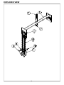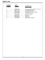
1
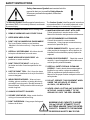
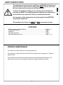
O P E R A T O R 'S M A N U A L FOR SERIAL NUMBERS: 1XFRG55XPD0000025 AND UP BOOM AND MANUAL HOIST 5NT162 This book consists of two manuals: The OPERATORS MANUAL in ENGLISH which contains all the information to install and operate this equipment . This manual includes a parts list. The Translated OPERATORS MANUAL which is the same as the English version only translated into another language. Refer to the English manual for a parts listing. 1 (REV. 05/01/2013) DEALER PREPARATION/INSTALLATION CHECK LIST Boom and Manual Hoist THIS CHECKLIST IS TO REMAIN IN OPERATOR’S MANUAL It is the responsibility of the dealer to complete the procedures listed below, then review this checklist with the customer upon the delivery or the sale of this equipment.The installation training goes over the basic operational functions of the equipment. To ensure adequate training, we require that the following items are reviewed by your John Deere Dealer. Please check off to ensure that you understand the following items before the installation training is complete: 5. Explain proper operation of hoist 6. Review General Maintenance 1. How the boom is attached to the machine. 2. All decals in place and readable. 3. Overall condition good (i.e. paint, welds, cable) 4. Review this manuals and RG5500 manuals Dealer's Signature Purchaser's Signature Safety IMPORTANT SAFETY MESSAGE FOR OWNERS/OPERATORS OF BOOM AND HOIST Safety is a primary concern in the design, manufacture, sale, and use of this boom and hoist. As manufacturer of equipment, we want to confirm to you, our customers, our concern for safety. We also want to remind you about the simple, basic, and common sense rules of safety when using a Boom and Hoist attachment. Failure to follow these rules can result in severe injury or death to operators or bystanders. It is essential that everyone involved in the assembly, operation, transport, maintenance, and storage of this equipment be aware, concerned, prudent, and properly trained in safety. Always use proper shielding as specified by the manufacturer. Never operate the attachment in any way not described in this manual. This Boom and Hoist system is designed to be attached to the back of a RG5500 Reel Grinder. Follow all instructions on installing this product. This product should not be used with any other equipment and can not be used without attaching it to the back of a RG5500 Reel Grinder. Improper installation of the product may cause the product to be unsafe. If you have any questions when instaling this product contact your John Deere Dealer. Read and fully understand all the safety practices discussed in this manual. All safety rules must be understood and followed by anyone who works with this equipment. 2 Before operating a Boom and Hoist system, an operator must read and understand all of the information in the operator's manual and in the safety signs attached to the product. A person who has not read or understood the operators’s manual and safety signs is not qualified to operate the unit. Accidents occur often on machines that are used by someone who has not read the operator’s manual and is not familiar with the equipment. If you do not have an operator’s manual or current production safety signs, contact the manufacturer or your dealer immediately. The Boom and Hoist system is designed for one-man operation. Never operate the equipment with anyone near, or in contact with, any part of the equipment. Be sure no one else, including bystanders, are near you when you operate this product. Following these simple, basic safety rules, as well as others identified in the operator’s manual and in product safety signs, will help minimize the possibility of accidents and increase your productivity in using this product. Be careful and make sure that everyone who operates the equipment knows and understands that this is a very powerful piece of machinery, and if used improperly, serious injury or death may result. The final responsibility for safety rests with the operator of this machine. TO THE DEALER: Assembly and proper installation of this product is the responsibility of the John Deere dealer. Read manual instructions and safety rules. Make sure all items on the Preparation Check List in the Operator’s Manual are completed before releasing equipment to the owner. TO THE OWNER: Read this manual before operating your Frontier equipment. Keep this manual handy for ready reference. Require all operators to read this manual carefully and become acquainted with all adjustments and operating procedures before attempting to operate the equipment. Replacement manuals can be obtained from your selling dealer. The equipment you have purchased has been carefully engineered and manufactured to provide dependable and satisfactory use. Like all mechanical products, it will require cleaning and upkeep. Lubricate the unit as specified. Please observe all safety information in this manual and safety decals on the equipment. For service, your authorized John Deere dealer has trained mechanics, genuine Frontier service parts, and the necessary tools and equipment to handle all ofyour service needs. Use only genuine Frontier service parts. 3 SAFETY INSTRUCTIONS Safety Awareness Symbols are inserted into this manual to alert you to possible Safety Hazards. Whenever you see these symbols, follow their instructions. The Warning Symbol identifies special instructions or procedures which, if not correctly followed, could result in personal injury. ! The Caution Symbol identifies special instructions or procedures which, if not strictly observed, could result in damage to or destruction of equipment. 1. KEEP GUARDS IN PLACE and in working order. 13. MAINTAIN BOOM AND HOIST WITH CARE. Follow instructions in service section of the 2. REMOVE WRENCHES AND OTHER TOOLS. Manual for lubrication and preventive maintenance. 3. KEEP WORK AREA CLEAN. 14. USE RECOMMENDED ACCESSORIES. Consult the manual for recommended 4. DON'T USE IN DANGEROUS ENVIRONMENT. accessories. Using improper accessories may Don't use Grinder in damp or wet locations. cause risk of personal injury. Machine is for indoor use only. Keep work area well lit. 15. CHECK DAMAGED PARTS. A guard, cable or other part that is damaged or will not perform its 5. KEEP ALL VISITORS AWAY. All visitors should intended function should be properly repaired or be kept a safe distance from work area. replaced. 6. MAKE WORK AREA CHILD-PROOF with padlocks or master switches. 16. KNOW YOUR EQUIPMENT. Read this manual carefully. Learn its application and limitations as well as specific potential hazards. 7. DON'T FORCE THE HOIST. It will do the job better and safer if used as specified in this manual. 17. KEEP ALL SAFETY DECALS CLEAN AND LEGIBLE. If safety decals become damaged or illegible for any reason, replace immediately. 8. USE THE RIGHT TOOL. Don't force the boom Refer to replacement parts illustrations in this and hoist or an attachment to do a job for which it Manual for the proper location and part numbers of was not designed. safety decals. 9. WEAR PROPER APPAREL. Wear no loose clothing, gloves, neckties, or jewelry which may get caught in moving parts. Nonslip footwear is recommended. Wear protective hair covering to contain long hair. 18. DO NOT OPERATE THIS EQUIPMENT WHEN UNDER THE INFLUENCE OF DRUGS, ALCOHOL, OR MEDICATION. 19. NEVER LEAVE A CUTTING UNIT SUSPENDED IN THE AIR. ALWAYS LOWER IT TO THE GROUND OR ONTO THE REEL GRINDER. 10. ALWAYS USE SAFETY GLASSES. 11. SECURE YOUR WORK. Make certain that the cutting unit is secured before lifting 12. DON'T OVERREACH. Keep proper footing and balance at all times. MAXIMUM LOAD CAPACITY IS 400LBS [180 kg] DO NOT ATTAMEPT TO LIFT ANYTHING HEAVIER THAN THE RATED CAPACITY. DAMAGE TO THE MACHINE OR SERIOUS INJURTY MAY OCCUR. 4 SAFETY INSTRUCTIONS This attachment is intended to be installed on a RG5500 Reel Grinder and should be used to raise or lower cutting units ONLY. Any use other than this may cause personal injury and void the warranty. ! To assure the quality and safety of your machine and to maintain the warranty, you MUST use original equipment manufacturers replacement parts and have any repair work done by a qualified professional. ALL operators of this equipment must be thoroughly trained BEFORE operating the equipment. This machine is for indoor use ONLY. Do NOT power wash machine. CONTENTS Safety Instructions/Specifications ....................................................... Page 2 - 6 Periodic Maintenance ................................................................................. Page 5 Installation .................................................................................................. Page 7 Operating Instruction .................................................................................. Page 8 Parts Lists/Exploded Views ........................................................................ Page 10 - 13 PERIODIC MAINTENANCE On a daily basis, clean the Boom and Hoist by wiping it off. On a daily basis, inspect the Boom and Hoist for loose fasteners or components. Tighten or adjust if found. On a daily basis, inspect the Boom and Hoist cable, hook and spreader assembly for any cracks, kinks, loose, worn or damaged components. Repair or replace any found. 5 SAFETY INSTRUCTIONS PLEASE TAKE SPECIAL NOTE OF THE FOLLOWING WARNING DECALS LOCATED ON THE GRINDER. FIG. 1 6 INSTALLATION INSTALLING WINCH AND BOOM To install the Boom Housing Weldment to the right rear side of the grinder: 1. Attach the Boom Housing Weldment with the four socket head cap screws 3/8-16 x 1”, the four 3/8” flat washers and the four lock washers from the Bag Assembly. See FIG. 3 and Page 10. 2. Install the Hook and Cable Assembly through the two pulleys on the Boom Assembly. Feed the cable down the center of the vertical tube of the Boom Weldment. FIG. 2 FIG. 2 3. Install the Boom Assembly with cable into the Boom Housing Weldment. WINCH HANDLE THIS SIDE Fasteners to attach the Boom Housing Weldment 4. Install the third Pulley with 3/8-16 x 1-3/4 Hex Head Cap Screw, 3/8 Flat Washer (2) and 3/8-16 Locknut in the bottom of the Boom Housing Weldment. See Page 10. 5. Install Winch using 3/8-16 x 3/4” Hex Head Cap Screw (2), 3/8 Lock washer (2), and 3/8 Flat Washer (2). The side that the handle mounts on should be toward the back of the machine. Install the winch handle. 6. Loop the cable around the lower pulley and install the cable on the winch per the winch instructions included with the kit. reuse existing screws 5NTB250816 (2) FIG. 3 7. Replace the lift handle on the boom side of the rear slide up guard door with the included Short Handle using the existing (2) 1/4-20 x 1/2 Button Head Socket Cap Screws, and (2) 1/4-20 Nylon Locknuts that were used to fasten the old handle. replace handle See FIG. 4. (5NT3706117) reuse existing nuts 5NTJ257100 (2) VERIFY ALL FASTENERS ARE TIGHT BEFORE USING BOOM AND HOIST ASSEMBLY TO LIFT A CUTTING UNIT. FIG. 4 7 OPERATION LIFTING THE REEL INTO POSITION Position the reel at the rear of the grinder on the floor so the front of the mower faces in the same direction as the front of the machine. See FIG. 5. Hook the winch spreader bar onto the reel. The clamps on the spreader bar should be spaced evenly along the mower, so they do not slide as the mower is being raised. Stand to the side of the mowing unit and at arms length, winch the mowing unit to height. Then guide it into position. FIG. 5 THE OPERATOR SHOULD BE POSITIONED AWAY FROM THE REEL. DO NOT STAND UNDERNEATH THE REEL AS IT IS BEING RAISED. GUIDE REEL AT ARMS LENGTH. DO NOT EXCEED THE BOOM CAPACITY OF 400 LBS (180 Kg). 8 THIS PAGE LEFT INTENTIONALLY BLANK FOR NOTE TAKING PURPOSES. 9 EXPLODED VIEW 10 PARTS LIST DIAGRAM NUMBER PART NUMBER 1 ............................ 2 ............................ 3 ............................ 4 ............................ 5 ............................ 6 ............................ 7 ............................ 8 ............................ .............................. 9 ............................ 10 .......................... 5NTB371201 .................... Hex Head Cap Screw 3/8-16 x 3/4Long 5NTB371611 .................... Socket Head Cap Screw 3/8-16 x 1 Long 5NTB372801 .................... Hex Head Cap Screw 3/8-16 x 1-3/4 Long 5NTJ377100 ..................... 3/8-16 Nylon Locknut 5NTK370001 .................... 3/8 Flat Washer 5NTK371501 .................... 3/8 Split Lockwasher 5NTRG5509556 ............... Boom Housing Weldment 5NT3706085..................... Boom Capacity Decal (English and Spanish) 5NT3706095..................... Boom Capacity Decal (English and French) 5NT3708578..................... Winch 5NT3709407..................... Hook and Cable Assembly 11 .......................... 12 .......................... 13 .......................... 14 .......................... 15 .......................... 5NT3709795..................... Pulley 5NTRG5009504 ............... Boom Weldment 5NTB250816 .................... Button Head Socket Screw 1/4-20 x 1/2 Long 5NTJ257100 ..................... 1/4-20 Full Nylon Locknut 5NT3706117 ..................... Door Handle (Short) DESCRIPTION *Hook & Cable Assembly is packed in carton. Install as shown (cable runs down middle of boom tube). 11 EXPLODED VIEW 12 PARTS LIST DIAGRAM NUMBER PART NUMBER 1 ............................ 2 ............................ 3 ............................ 4 ............................ 5 ............................ 6 ............................ 7 ............................ 8 ............................ 9 ............................ 5NTB372011 Socket Head Cap Screw 3/8-16 x 1-1/4 Long 5NTJ317100 ..................... 5/16-18 Nylon Locknut Full 5NTJ377100 ..................... 3/8-16 Nylon Locknut Full 5NT3599028 .................... Flat Washer .375 x 1.0 x .188 Thick 5NT3706085 .................... Load Capacity Decal 5NT3709316 .................... U-Bolt 5/16-18 x 3 5NT6009102 .................... Grab Hook 5NT6329061 .................... Chain 44.6” 5NT6509590 .................... Spreader Bar Weldment DESCRIPTION . . . . . . . . . . . . . . . . . . . . 13 14 MANUAL DEL OPERADOR NÚMERO DE SERIE: DESDE 1XFRG55XPD0000025 - BRAZO CON ELEVADOR MANUAL 5NT16200901 (REV. 5/1/2013) 1 LISTA DE COMPROBACIÓN DE LA INSTALACIÓN/PREPARACIÓN DEL DISTRIBUIDOR BRAZO CON ELEVADOR MANUAL ESTA LISTA DE COMPROBACIÓN DEBE PERMANECER EN EL MANUAL DEL OPERADOR El distribuidor tiene la responsabilidad de realizar los procedimientos que se enumeran a continuación, y luego, revisar la lista de comprobación con el cliente en el momento de la entrega o venta de este equipo. La capacitación sobre la instalación cubre las funciones operativas básicas del equipo. Para garantizar una capacitación apropiada, establecemos como requisito que su distribuidor de John Deere revise los puntos a continuación. Marque para asegurarse de comprender los puntos a continuación antes de completar la capacitación sobre la instalación: 5. Explique el uso correcto del elevador. 1. Controlar cómo está unido el brazo a la máquina. 2. Todas las calcomanías están en su lugar y son legibles. 6. Revise el mantenimiento general. 3. Se encuentra en buenas condiciones generales (es decir, de pintura, soldaduras, instalación eléctrica). 4. Revise este manual y los manuales de la RG5500 Firma del distribuidor Firma del comprador Seguridad MENSAJE DE SEGURIDAD IMPORTANTE PARA LOS PROPIETARIOS/OPERADORES DEL BRAZO CON ELEVADOR La seguridad es una preocupación principal en el diseño, la fabricación, la venta y el uso de este brazo con elevador. Como fabricantes del equipo, deseamos confirmarles a ustedes, nuestros clientes, nuestra preocupación por la seguridad. También deseamos recordarles las reglas simples, básicas y de sentido común acerca de la seguridad cuando utilicen un brazo con elevador. No seguir estas reglas puede resultar en lesiones graves para el operador o las personas cercanas al área, e incluso la muerte. Es esencial que toda persona involucrada en el montaje, la operación, el transporte, el mantenimiento y el almacenamiento de este equipo sea consciente y se preocupe por la seguridad, sea prudente y cuente con la capacitación adecuada sobre seguridad. Siempre utilice la protección adecuada, como lo especifica el fabricante. Nunca use este equipo acoplable de una forma distinta a la descrita en este manual. El sistema de brazo con elevador está diseñado para ser acoplado a la parte trasera de una rectificadora de carrete RG5500. Siga todas las instrucciones al instalar este producto. Este producto no debe ser usado con ningún otro equipo y no puede usarse si no está acoplado a la parte trasera de una rectificadora de carrete RG5500. El producto puede no ser seguro si no se instala correctamente. Si tiene alguna pregunta al instalar este producto, póngase en contacto con su distribuidor de John Deere. Lea y comprenda completamente todas las prácticas de seguridad que se especifican en este manual. Toda persona que trabaje con este equipo debe comprender y seguir todas las reglas de seguridad. 2 Antes de poner en funcionamiento el sistema de brazo con elevador, un operador debe leer y comprender toda la información del manual del operador y de las señales de seguridad que se encuentran sobre el producto. Una persona que no hayan leído o comprendido el manual del operador y las señales de seguridad no está calificada para poner en funcionamiento la unidad. A menudo, ocurren accidentes en máquinas que son utilizadas por una persona que no leyó el manual del operador y no se familiarizó con el equipo. Si no cuenta con un manual del operador o con las señales de seguridad actualizadas, póngase en contacto con el fabricante o con su distribuidor de inmediato. El sistema de brazo con elevador está diseñado para ser usado por una sola persona. Nunca ponga en funcionamiento el equipo cuando alguien esté cerca o en contacto con cualquier parte del equipo. Asegúrese de que nadie más, lo que incluye cualquier persona cercana al área, esté cerca de usted cuando ponga en funcionamiento este producto. Seguir estas reglas de seguridad simples y básicas, así como también otras especificadas en el manual del operador y en las señales de seguridad del producto, ayudará a minimizar la posibilidad de accidentes y aumentará su productividad al utilizar este producto. Tenga la precaución y asegúrese de que toda persona que ponga en funcionamiento el equipo sepa y comprenda que es una máquina muy poderosa y que, de ser utilizada indebidamente, puede causar lesiones graves o la muerte. La responsabilidad final sobre la seguridad recae en el operador de esta máquina. PARA EL DISTRIBUIDOR: El montaje y la instalación adecuada de este producto son responsabilidad del distribuidor de John Deere. Lea las instrucciones y las reglas de seguridad del manual. Asegúrese de que se hayan realizado todos los puntos de la Lista de comprobación de preparación del Manual del operador antes de entregar el equipo al propietario. PARA EL PROPIETARIO: Lea este manual antes de poner en funcionamiento su equipo Frontier. Conserve este manual al alcance de su mano para tener una referencia rápida. Solicite a todos los operadores que lean este manual con detenimiento y se familiaricen con todos los ajustes y procedimientos operativos antes de intentar poner en funcionamiento el equipo. Puede obtener los manuales de repuesto de su distribuidor. El equipo que adquirió ha sido diseñado y fabricado cuidadosamente para brindar un uso confiable y satisfactorio. Como todos los productos mecánicos, requerirá limpieza y mantenimiento. Lubrique la unidad como se especifica. Tenga en cuenta toda la información de seguridad que incluye este manual y las calcomanías de seguridad sobre el equipo. Para obtener servicio, su distribuidor autorizado John Deere cuenta con mecánicos capacitados, piezas de repuesto Frontier genuinas, y las herramientas y los equipos necesarios para dar respuesta a todas sus necesidades de servicio. Utilice solo piezas de servicio Frontier genuinas. 3 INSTRUCCIONES DE SEGURIDAD ! Los símbolos de seguridad están incluidos en este manual para que esté alerta de los posibles riesgos de seguridad. Siempre que vea estos símbolos, siga sus instrucciones. El símbolo de advertencia identifica instrucciones o procedim ientos especiales que, si no se siguen correctamente, pueden resultar en lesiones personales. 1. MANTENGA LOS PROTECTORES EN SU LUGAR y buenas condiciones de operación. El Símbolo de precaución identifica instrucciones o procedimientos especiales que, si no se obedecen estrictamente, pueden resultar en daños al equipo e incluso su destrucción. 13. REALICE EL MANTENIMIENTO DEL BRAZO CON ELEVADOR CON CUIDADO. Siga las instrucciones de la sección de servicio del Manual para la lubricación y el mantenimiento preventivos. 2. QUITE LAS LLAVES Y OTRAS HERRAMIENTAS. 3. MANTENGA LIMPIA EL ÁREA DE TRABAJO. 4. NO UTILICE EL EQUIPO EN ENTORNOS PELIGROSOS. No utilice la rectificadora en zonas húmedas o mojadas. La máquina es solo para uso en interiores. Mantenga el área de trabajo bien iluminada. 14. UTILICE LOS ACCESORIOS RECOMENDADOS. Consulte el manual para obtener información acerca de los accesorios recomendados. Utilizar accesorios inadecuados puede aumentar el riesgo de lesiones personales. 5. MANTENGA A TODOS LOS VISITANTES ALEJADOS. Todos los visitantes deben mantenerse a una distancia segura del área de trabajo. 15. VERIFIQUE LAS PIEZAS DAÑADAS. Un protector, cable u otra pieza que estén dañados o que no cumplan la función que deben realizar deben repararse o reemplazarse adecuadamente. 6. ACONDICIONE EL ÁREA DE TRABAJO PARA QUE SEA A PRUEBA DE NIÑOS con candados e interruptores principales. 16. CONOZCA SU EQUIPO. Lea este manual con atención. Conozca sus aplicaciones y limitaciones, así como también los peligros potenciales específicos. 7. NO FUERCE EL ELEVADOR. El equipo realizará un trabajo mejor y más seguro si se utiliza según las especificaciones de este manual. 8. 9. 10. 11. 17. MANTENGA TODAS LAS CALCOMANÍAS DE SEGURIDAD LIMPIAS Y LEGIBLES. Si las calcomanías están dañadas o ilegibles por alguna razón, reemplácelas inmediatamente. Tome como UTILICE LA HERRAMIENTA CORRECTA. No fuerce referencia las ilustraciones de las piezas de repuesto el brazo con elevador u otro equipo acoplable a realizar que contiene este Manual para ubicarlas un trabajo para el que no fueron diseñados. adecuadamente y obtener los números de pieza de las calcomanías de seguridad. UTILICE LA VESTIMENTA ADECUADA. No vista indumentaria suelta, guantes, corbatas ni alhajas que 18. NO PONGA EN FUNCIONAMIENTO ESTE EQUIPO puedan atascarse en las piezas en movimiento. Se BAJO LA INFLUENCIA DE DROGAS, ALCOHOL O recomienda el uso de calzado antideslizante. Utilice MEDICAMENTOS. una redecilla protectora del cabello para contener el cabello largo. 19. NUNCA DEJE UNA UNIDAD DE CORTE SUSPENDIDA EN EL AIRE. SIEMPRE COLÓQUELA SIEMPRE UTILICE GAFAS DE SEGURIDAD. EN EL PISO O SOBRE UNA RECTIFICADORA DE CARRETE. ASEGURE SU TRABAJO. Asegúrese de que la unidad LA CAPACIDAD DE CARGA MÁXIMA ES de corte esté bien asegurada antes de levantarla 12. NO ADOPTE POSTURAS FORZADAS. Mantenga una posición firme y equilibrada en todo momento. 4 DE 180 kg [400 lb] NO INTENTE LEVANTAR NADA QUE TENGA UN PESO MAYOR A LA CAPACIDAD DE CARGA ESPECIFICADA. ESTO PUEDE PROVOCAR DAÑOS A LA MÁQUINA O LESIONES GRAVES. INSTRUCCIONES DE SEGURIDAD Este equipo acoplable está pensado para ser instalado sobre una rectificadora de carrete RG5500 y debe ser usado ÚNICAMENTE para subir o bajar unidades de corte. Cualquier uso diferente a este puede causar lesiones personales y anular la garantía. ! Para asegurar la calidad y seguridad de su máquina y para mantener la garantía, usted DEBE utilizar piezas de repuesto del fabricante del equipo original y encargar cualquier trabajo de reparación a un profesional calificado. TODOS los operadores de este equipo deben estar debidamente capacitados ANTES de poner en funcionamiento el equipo. Esta máquina es para uso en interiores ÚNICAMENTE. NO Lave la máquina con una hidrolavadora. CONTENIDO Instrucciones de seguridad/Especificaciones ............................................ Páginas 2-6 Mantenimiento periódico ........................................................................... Página 5 Instalación ................................................................................................. Página 7 Instrucciones de operación ....................................................................... Página 8 Listas de partes/Vistas expandidas ........................................................... Páginas 10-13 MANTENIMIENTO PERIÓDICO Diariamente, limpie el brazo con elevador con un trapo. Diariamente, inspeccione el brazo con elevador en busca de sujetadores o componentes sueltos. Ajústelos si los hay. Diariamente, inspeccione el cable del brazo con elevador, el gancho y la barra esplegadora para verificar que no haya grietas, torceduras o componentes dañados o desgastados. Repárelos o reemplácelos si los hay. 5 INSTRUCCIONES DE SEGURIDAD PRESTE ESPECIAL ATENCIÓN A LAS CALCOMANÍAS DE ADVERTENCIA QUE APARECEN A CONTINUACIÓN Y QUE ESTÁN UNBICADAS SOBRE LA MÁQUINA. FIG. 1 6 INSTALACIÓN INSTALACIÓN DEL CABRESTANTE Y EL BRAZO Para instalar el soporte para el brazo al lado posterior derecho de la rectificadora: 1. Instale el soporte para el brazo con los cuatro tornillos de cabeza hueca de 3/8-16 x 1”, las cuatro arandelas planas de 3/8” y las cuatro arandelas de seguridad de la bolsa. Vea la FIG. 3 y la página 10. 2. Instale el gancho y el cable de montaje por las dos poleas montadas sobre el brazo. Desenrolle el cable y hágalo pasar a través del centro del tubo vertical del soporte del brazo. FIG. 2 3. Instale el brazo con cable en el soporte para el brazo. 4. Instale la tercera polea en la parte inferior del soporte para el brazo con un tornillo de cabeza hexagonal de 3/8-16 x 1-3/4, dos arandelas planas de 3/8 y una contratuerca de 3/8-16. Vea la página 10. LA MANIJA DEL CABRESTANTE DE ESTE LADO Sujetadores para el soporte para el brazo 5. Instale el cabrestante usando dos tornillos de cabeza hexagonal de 3/8-16 x 3/4”, dos arandelas de seguridad de 3/8 y dos arandelas planas de 3/8. El lado sobre el que se monta la manija debe estar hacia la parte trasera de la máquina. Instale la manija del cabrestante. FIG. 3 6. Pase el cable alrededor de la polea inferior e instale el cable en el cabrestante según las instrucciones del cabrestante que vienen con el paquete. 5NTB250816 (2) 7.Vuelva a colocar la manija en el lado de la pluma de la puerta retaguardia con el el mango corto. (5NT3706117) utilizar el hardware existente. (5NT3706117) VERIFIQUE QUE TODOS LOS SUJETADORES ESTÉN BIEN AJUSTADOS ANTES DE USAR EL BRAZO CON ELEVADOR PARA LEVANTAR UNA UNIDAD DE CORTE. 5NTJ257100 (2) 7 OPERACIÓN DEL EQUIPO LEVANTAR EL CARRETE Y COLOCARLO EN SU LUGAR Ubique el carrete en el piso detrás de la rectificadora de manera que el frente de la segadora apunte en la misma dirección que el frente de la máquina. Vea la FIG. 4. Enganche la barra esplegadora del cabrestante al carrete. Las abrazaderas de la barra esplegadora deben estar espaciadas en forma pareja a lo largo de la segadora, para que no se deslicen mientras esta se eleva. Párese a un costado de la segadora y, a un brazo de distancia, use el cabestrante para elevarla. Luego guíela hasta su posición. FIG. 4 EL OPERADOR DEBE UBICARSE LEJOS DEL CARRETE. NO SE PARE DEBAJO DEL CARRETE CUANDO SE LO ESTÁ LEVANTANDO. GUÍE EL CARRETE A UN BRAZO DE DISTANCIA. NO EXCEDA LA CAPACIDAD DE CARGA DEL BRAZO DE 180 KG (400 LB). 8 ESTA PÁGINA ESTÁ EN BLANCO INTENCIONALMENTE CON EL OBJETIVO DE TOMAR NOTAS. 9 PART NUMBER 5NT16207951 10