1
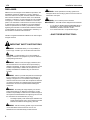
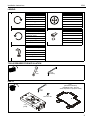
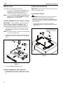
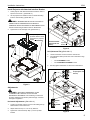
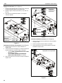
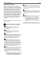
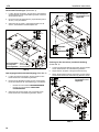
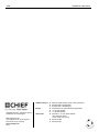
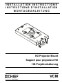
INSTALLATION INSTRUCTIONS
INSTRUCTIONS D'INSTALLATION
MONTAGEANLEITUNG
HD Projector Mount
Support pour projecteur HD
HD-Projektorhalterung
VCM
VCM
Installation Instructions
DISCLAIMER
Milestone AV Technologies and its affiliated corporations and
subsidiaries (collectively "Milestone"), intend to make this
manual accurate and complete. However, Milestone makes no
claim that the information contained herein covers all details,
conditions or variations, nor does it provide for every possible
contingency in connection with the installation or use of this
product. The information contained in this document is subject
to change without notice or obligation of any kind. Milestone
makes no representation of warranty, expressed or implied,
regarding the information contained herein. Milestone assumes
no responsibility for accuracy, completeness or sufficiency of
the information contained in this document.
Chief® is a registered trademark of Milestone AV Technologies.
All rights reserved.
IMPORTANT SAFETY INSTRUCTIONS
WARNING: A WARNING alerts you to the possibility of
serious injury or death if you do not follow the instructions.
CAUTION: A CAUTION alerts you to the possibility of
damage or destruction of equipment if you do not follow the
corresponding instructions.
WARNING: Failure to read, thoroughly understand, and
follow all instructions can result in serious personal injury,
damage to equipment, or voiding of factory warranty! It is the
installer’s responsibility to make sure all components are
properly assembled and installed using the instructions
provided.
WARNING: Failure to provide adequate structural strength
for this component can result in serious personal injury or
damage to equipment! It is the installer’s responsibility to
make sure the structure to which this component is attached
can support five times the combined weight of all equipment.
Reinforce the structure as required before installing the
component.
WARNING: Exceeding the weight capacity can result in
serious personal injury or damage to equipment! It is the
installer’s responsibility to make sure the combined weight of
all components located between the supporting structure and
the VCM does not exceed 250 lbs (113.4 kg).
•
The weight capacity of the VCM may be LIMITED to the
lowest weight capacity of any other component located
between the VCM and the supporting structure!
WARNING: Use this mounting system only for its intended
use as described in these instructions. Do not use
attachments not recommended by the manufacturer.
2
WARNING: Never operate this mounting system if it is
damaged. Return the mounting system to a service center for
examination and repair.
WARNING: Do not use this product outdoors.
IMPORTANT ! : The VCM mount is designed to be mounted to:
•
•
a 1-1/2" NPT or NPSM following ANSI/ASME B1.20.1
(Schedule 40, 0.154" minimum thickness aluminumASTM B221) threaded extension column;
a UL Listed Chief LPK-1 low profile mounting kit.
--SAVE THESE INSTRUCTIONS--
Installation Instructions
VCM
LEGEND
Tighten Fastener
Adjust
Apretar elemento de fijación
Ajustar
Befestigungsteil festziehen
Einstellen
Apertar fixador
Ajustar
Serrare il fissaggio
Regolare
Bevestiging vastdraaien
Afstellen
Serrez les fixations
Ajuster
Loosen Fastener
Open-Ended Wrench
Aflojar elemento de fijación
Llave de boca
Befestigungsteil lösen
Gabelschlüssel
Desapertar fixador
Chave de bocas
Allentare il fissaggio
Chiave a punte aperte
Bevestiging losdraaien
Steeksleutel
Desserrez les fixations
Clé à fourche
Hex-Head Wrench
Llave de cabeza hexagonal
Sechskantschlüssel
Chave de cabeça sextavada
Chiave esagonale
Zeskantsleutel
Clé à tête hexagonale
TOOLS REQUIRED FOR INSTALLATION
1/2"
9/16"
5/32"
(included)
PARTS
D (1)
[HB interface bracket]
(EXAMPLE ONLY - Bracket
varies dependent on projector model)
B (1)
5/32"
C (1)
5/16-18 x 3/8"
A (1)
[VCM]
3
VCM
Installation Instructions
INSTALLATION
INSTALLING PROJECTOR
The VCM mount is designed to be mounted to:
IMPORTANT ! : Model VCM uses Chief "HB" Series interface
•
•
a 1-1/2" NPT or NPSM following ANSI/ASME B1.20.1
(Schedule 40, 0.154" minimum thickness aluminumASTM B221) threaded extension column; or
a UL Listed Chief LPK-1 low profile mounting kit.
brackets. (See Parts drawing.)
Install Interface Bracket
NOTE: Proceed to Installing VCM Mount to NPT Extension
Column section or Installing VCM Mount to LPK-1
Mount Kit section, as appropriate.
WARNING: IMPROPER INSTALLATION CAN LEAD TO
PROJECTOR FALLING RESULTING IN SERIOUS
PERSONAL INJURTY OR DAMAGE TO EQUIPMENT. DO
NOT substitute hardware. Use only the hardware provided by
the manufacturer.
Installing VCM Mount to NPT Extension Column
IMPORTANT ! : These installation instructions assume
that a 1-1/2" NPT or NPSM (Schedule 40, 0.154"
minimum thickness aluminum - ASTM B221) pipe (not
included) has been properly installed and is in place.
1.
1.
Secure interface bracket to VCM using installation
instructions and hardware provided with interface bracket.
((Siehe Abb. 2)
Thread the VCM mount (A) onto the existing 1-1/2" NPT
pipe until tight with a minimum of four threads engaged.
((Siehe Abb. 1)
Example Only
(Interface bracket varies
dependent on projector
model)
NOTE: Ensure that long edge of VCM mount is located parallel
1
to the screen. ((Siehe Abb. 1)
2.
Tighten the 5/16-18 x 3/8" set screw (C) into the VCM mount
threaded collar to prevent movement of the VCM. ((Siehe
Abb. 1)
NPT
pipe
2
(C) x 1
1
(A)
Figure 2
SC
RE
E
N
Figure 1
3.
Proceed to Projector Installation section.
Installing VCM Mount to LPK-1 Mount Kit
1.
4
Install VCM mount (A) to LPK-1 low profile mount kit (not
included) following instructions included with LPK-1 mount
kit.
Installation Instructions
VCM
Install Projector with Attached Interface Bracket
1.
Orient projector with attached interface bracket so that it is
square to the screen. ((Siehe Abb. 3)
2.
1
x4
Lift the projector and install it to the four studs extending
from the VCM housing. ((Siehe Abb. 3)
3
WARNING: IMPROPER INSTALLATION CAN LEAD TO
PROJECTOR FALLING RESULTING IN SERIOUS
PERSONAL INJURY OR DAMAGE TO EQUIPMENT! Ensure
that the VCM housing is seated in slots on HB bracket!
3.
2
Tighten the four 5/16" flange nuts. ((Siehe Abb. 3)
Example Only
(Interface bracket varies
dependent on projector
model)
3
(Interface bracket
and projector not
shown)
x2
Top slide
bracket
Figure 4
Roll (Horizontal Tilt) ((Siehe Abb. 5)
2
4.
Loosen three bolts on each end of the VCM mount.
5.
Turn adjustment bolts (one at each end of VCM mount top)
as required.
6.
•
Turn CLOCKWISE to raise
•
Turn COUNTERCLOCKWISE to lower
Securely tighten three bolts on each end of VCM mount.
4
1
x3
SC
RE
EN
(Interface bracket
and projector not
shown)
6
3
x2
Figure 3
Adjustments
WARNING: MOUNTING HARDWARE IS TO BE
LOOSENED ONLY ENOUGH TO ALLOW FOR
NECESSARY MOVEMENT. Over-loosening or removal of
mounting hardware may result in personal injury or serious
damage to equipment!
Horizontal Adjustments ((Siehe Abb. 4)
1.
Loosen, but do NOT remove, the four nuts holding the top
slide bracket on the VCM mount.
2.
Adjust VCM mount up to 1-1/2" in any direction.
3.
Tighten the nuts loosened (in Step 1) on the top slide
bracket.
5
RAISE
x2
4
LOWER
x3
6
Figure 5
5
VCM
Installation Instructions
Pitch (Vertical Elevation) ((Siehe Abb. 6)
7.
Loosen two outside bolts on each end of the VCM mount.
8.
Tilt projector to desired direction.
9.
Securely tighten two outside bolts on each end of VCM
mount.
(Interface bracket
and projector not
shown)
7
x2
9
8
7
x2
9
Figure 6
6
Installation Instructions
VCM
CLAUSES DE NON-RESPONSABILITÉ
Milestone AV Technologies, ses filiales et entreprises affiliées
(« Milestone ») ont fait en sorte que ce manuel soit exact et
exhaustif. Cependant, Milestone ne garantit pas que les
informations mentionnées au présent document couvrent tous
les aspects, conditions ou variations dans le détail ; pas plus
qu'elle ne fournit de solution pour chaque imprévu lié au type
d'installation ou d'utilisation de ce produit. Les informations
mentionnées au présent document sont susceptibles d'être
modifiées sans aucun préavis ni obligation. Milestone ne
consent aucune garantie, expresse ou implicite, au titre des
informations contenues dans le présent document. Milestone
ne garantit pas que les informations mentionnées au présent
document soient exactes, exhaustives et suffisantes.
Chief® est une marque déposée de Milestone AV Technologies.
Tous droits réservés.
DIRECTIVES DE SÉCURITÉ IMPORTANTES
AVERTISSEMENT : N'utiliser ce système de montage que
pour l'usage prévu conformément à ces directives. Ne pas
utiliser d'accessoires non recommandés par le fabricant.
AVERTISSEMENT : Ne jamais faire fonctionner ce système
de montage s'il est endommagé. Dans ce cas, renvoyer le
système à un service technique pour examen et réparation.
AVERTISSEMENT : Ne pas utiliser ce produit à l'extérieur.
IMPORTANT ! : Le support VCM est conçu pour être fixé à :
•
•
une colonne d'extension filetée NPT ou NPSM 1-1/2"
codée suivant le standard ANSI/ASME B1.20.1
(aluminium série 40 d'une épaisseur minimale de
0,154" – ASTM B221) ;
un kit de montage peu encombrant Chief LPK-1
homologué UL
--RANGER CES CONSIGNES EN LIEU SÛR--
AVERTISSEMENT : Un AVERTISSEMENT vous indique
qu'il existe un risque de blessures graves ou de décès si
vous ne suivez pas les instructions.
MISE EN GARDE : Une MISE EN GARDE vous indique qu'il
existe un risque de dommages ou de destruction du matériel si
vous ne suivez pas les instructions correspondantes.
AVERTISSEMENT : Le fait de ne pas lire, de ne pas bien
comprendre et de ne pas suivre toutes les instructions peut
entraîner des blessures corporelles graves, endommager
l'équipement ou annuler la garantie du fabricant ! Il est de la
responsabilité de l'installateur de s'assurer que tous les
composants sont correctement montés et installés
conformément aux instructions fournies.
AVERTISSEMENT : Une résistance structurelle non
appropriée pour ce composant peut entraîner des blessures
corporelles graves ou endommager l'équipement ! Il est de la
responsabilité de l'installateur de s'assurer que la structure à
laquelle ce composant est attaché peut supporter cinq fois le
poids total de l'équipement. Si nécessaire, renforcez la
structure avant d'installer cet élément.
AVERTISSEMENT : Le dépassement de capacité de poids
peut causer de graves blessures corporelles ou endommager
le matériel ! Il est de la responsabilité de l'installateur de
s'assurer que le poids combiné de tous les composants
situés entre la structure de support et le VCM ne dépasse
pas 113,4 kg (250 lbs).
•
La capacité de poids du VCM peut être LIMITÉE à la
capacité de poids la plus basse de tout autre élément
situé entre le VCM et la structure de support !
7
VCM
Installation Instructions
OUTILS NÉCESSAIRES À L'INSTALLATION
12,7 mm (1/2")
14,3 mm (9/16")
4,0 mm (5/32")
( inclus )
PIÈCES
D (1)
[Patte de fixation d'interface HB]
( À TITRE D'EXEMPLE – La patte de fixation
varie en fonction du modèle de projecteur)
B (1)
5/32"
C (1)
5/16-18 x 3/8"
A (1)
[VCM]
INSTALLATION
Tuyau
NPT
Le support VCM est conçu pour être fixé à :
•
•
une colonne d'extension filetée NPT ou NPSM 1-1/2"
codée suivant le standard ANSI/ASME B1.20.1
(aluminium série 40 d'une épaisseur minimale de
0,154" – ASTM B221) ; ou
un kit de montage peu encombrant Chief LPK-1
homologué UL
2
1
REMARQUE : Passez à la section Installation du support
VCM à la colonne d'extension NPT ou à la
section Installation du support VCM au kit de
montage LPK-1, selon le cas.
(A)
Installation du support VCM à la colonne
d'extension NPT
IMPORTANT ! : Ces instructions d'installation supposent qu'un
tuyau NPT ou NPSM de 1-1/2" (aluminium série 40 d'une
épaisseur minimale de 0,154" – ASTM B221) (non inclus) a été
correctement installé et est en place.
1.
Enfilez le support VCM (A) sur le tuyau NPT de 1-1/2" en
serrant bien avec un minimum de quatre filets engagés.
(Voir la Figure 1)
REMARQUE : Assurez-vous que le bord long du support VCM
est parallèle à l'écran. (Voir la Figure 1)
2.
8
Serrez la vis de calage 5/16-18 x 3/8" (C) dans le collier
fileté de montage du VCM pour empêcher le VCM de
bouger. (Voir la Figure 1)
Figure 1
3.
Passez à la section Installation du projecteur.
(C) x 1
Installation Instructions
VCM
Installation du support VCM au kit de
montage LPK-1
Installation du projecteur avec la patte de
fixation fournie
1.
1.
Orientez le projecteur avec la patte de fixation fournie
de manière à ce qu'il soit perpendiculaire à l'écran.
(Voir la Figure 3)
2.
Soulevez le projecteur et fixez-le aux quatre montants
qui s'étendent du boîtier. (Voir la Figure 3)
Installez le support VCM (A) au kit de montage peu encombrant
LPK-1 (non inclus) en suivant les instructions incluses avec le kit
de montage LPK-1.
INSTALLATION DU PROJECTEUR
IMPORTANT ! : Le modèle VCM utilise des pattes de fixation
AVERTISSEMENT : UNE MAUVAISE INSTALLATION
d'interface de série "HB" de Chief. (Voir le dessin Pièces.)
PEUT PROVOQUER UN LA CHUTE DU PROJECTEUR ET
ENDOMMAGER CELUI-CI, VOIRE ENTRAÎNER DES
BLESSURES CORPORELLES GRAVES ! Assurez-vous que le
boîtier du VCM est positionné dans les fentes du support HB !
Installation de la patte de fixation d'interface
3.
Serrez les quatre écrous à embase 5/16". (Voir la Figure 3)
AVERTISSEMENT : UNE MAUVAISE INSTALLATION
PEUT PROVOQUER LA CHUTE DU PROJECTEUR ET
ENDOMMAGER CELUI-CI, VOIRE ENTRAÎNER DES
BLESSURES CORPORELLES GRAVES. NE PAS substituer le
matériel. Utilisez uniquement le matériel fourni par le fabricant.
1.
À titre d'exemple
(La patte de fixation
d'interface varie en
fonction du modèle
de projecteur)
Fixez la patte de fixation au VCM en suivant les instructions
d'installation et en utilisant le matériel fourni avec la patte de
fixation. (Voir la Figure 2)
3
x2
À titre d'exemple
(La patte de fixation
d'interface varie en fonction
du modèle de projecteur)
1
2
1
3
x2
Figure 3
Figure 2
Réglages
AVERTISSEMENT : LE MATERIEL DE FIXATION NE
DOIT ÊTRE DESSERRÉ QUE SUFFISAMMENT POUR
PERMETTRE LES MOUVEMENTS NÉCESSAIRES.
Un desserrage excessif ou le retrait du matériel de fixation
peut entraîner des blessures corporelles graves ou
sérieusement endommager l'équipement !
9
VCM
Installation Instructions
Réglages horizontaux (Voir la Figure 4)
1.
(Patte de fixation
Desserrez, mais NE retirez PAS, les quatre écrous maintenant
le support coulissant supérieur sur le support VCM.
2.
Réglez le support VCM jusqu'à 38 mm (1-1/2") dans tous
les sens.
3.
Serrez les écrous desserrés (à l'étape 1) sur le support
coulissant supérieur.
4
d'interface
x3
6
et projecteur non
représentés)
1
x4
3
2
RELEVER
x2
5
4
ABAISSER
x3
6
(Patte de fixation
d'interface
Support
et projecteur non coulissant
représentés)
supérieur
Figure 4
Ondulation (inclinaison horizontale) (Voir la Figure 5)
4.
Desserrez les trois boulons à chaque extrémité du
support VCM.
5.
Tournez les boulons de réglage (un à chaque extrémité de
la partie supérieure du support VCM) si nécessaire.
•
•
6.
Tournez DANS LE SENS DES AIGUILLES D'UNE
MONTRE pour relever
Tournez DANS LE SENS CONTRAIRE DES
AIGUILLES D'UNE MONTRE pour abaisser
Figure 5
Inclinaison (élévation verticale) (Voir la Figure 6)
7.
Desserrez les deux boulons extérieurs à chaque extrémité
du support VCM.
8.
Inclinez le projecteur dans la direction souhaitée.
9.
Serrez fermement les deux boulons extérieurs à chaque
extrémité du support VCM.
(Patte de fixation d'interface
et projecteur non représentés)
7
x2
9
Serrez fermement les trois boulons à chaque extrémité du
support VCM.
8
7
x2
9
Figure 6
10
Installation Instructions
VCM
HAFTUNGSAUSSCHLUSS
Milestone AV Technologies sowie seine konzerneigenen
Unternehmen und Tochtergesellschaften (zusammen "Milestone")
haben versucht, dieses Handbuch so genau und vollständig als
möglich zu gestalten. Milestone erhebt jedoch weder Anspruch auf
Vollständigkeit der Einzelheiten, Bedingungen und Änderungen
der hierin enthaltenen Informationen, noch übernimmt das
Unternehmen irgendeine Haftung für eventuelle Schadensfälle in
Verbindung mit der Installation oder Verwendung dieses Produkts.
Die in diesem Dokument enthaltenen Informationen können ohne
vorherige Ankündigung oder sonstige Verpflichtungen jederzeit
geändert werden. Milestone schließt jegliche ausdrückliche oder
stillschweigende Zusicherung und Gewährleistung bezüglich der
hierin enthaltenen Informationen aus. Milestone übernimmt
keinerlei Verantwortung für die Genauigkeit, Vollständigkeit oder
Angemessenheit der in diesem Dokument enthaltenen
Informationen.
Chief® ist eine eingetragene Marke von Milestone AV Technologies.
Alle Rechte vorbehalten.
WARNUNG: Verwenden Sie das Halterungssystem nur für
den vorgesehenen, in der Anleitung beschriebenen Zweck.
Verwenden Sie keine Zubehörteile, die nicht vom Hersteller
empfohlen wurden.
WARNUNG: Verwenden Sie das Halterungssystem nie in
beschädigtem Zustand. Bringen Sie das Halterungssystem in
diesem Fall für die Fehlersuche und Reparatur zu einem
Service-Center.
WARNUNG: Verwenden Sie das Produkt nie im Freien.
WICHTIG! Die VCM-Halterung eignet sich zur Montage an:
•
•
eine Ausziehsäule mit 1-1/2"-NPT- oder NPSM-Gewinde
gemäß ANSI/ASME B1.20.1 (Schedule 40, 0,154"
Mindestwandstärke aus Aluminium - ASTM B221);
ein UL-konformes Chief LPK-1-Befestigungsset mit
flachem Profil.
--BEWAHREN SIE DIESE ANWEISUNGEN AUF--
WICHTIGE SICHERHEITSHINWEISE
WARNUNG: WARNUNG weist darauf hin, dass bei
Nichtbefolgung der Anweisungen Verletzungs- oder
Lebensgefahr besteht.
VORSICHT: VORSICHT weist darauf hin, dass bei
Nichtbefolgung der Anweisungen die Möglichkeit von
Geräteschäden besteht.
WARNUNG: Die Nichtbefolgung dieser Anweisungen kann
zu schweren Verletzungen und Geräteschäden sowie zum
Erlöschen der Garantie führen. Der Monteur hat dafür zu
sorgen, dass alle Bauelemente nach den beiliegenden
Anweisungen montiert und installiert werden.
WARNUNG: Wenn dieses Bauelement nicht an einer
Konstruktion mit der erforderlichen Tragfähigkeit montiert wird,
kann dies zu schweren Verletzungen oder Geräteschäden
führen! Der Monteur hat dafür zu sorgen, dass die Konstruktion,
an der das Bauelement angebracht wird, über die erforderliche
Tragfähigkeit verfügt. Die Konstruktion muss das fünffache
Gesamtgewicht des Geräts tragen können. Verstärken Sie vor
der Montage des Bauelements ggf. die Konstruktion.
WARNUNG: Das Überschreiten der maximalen Tragkraft
kann zu schweren Verletzungen oder Geräteschäden führen!
Der Monteur ist dafür verantwortlich, sicherzustellen,
dass das Gesamtgewicht aller Komponenten zwischen der
tragenden Konstruktion und der VCM 113,4 kg (250 lbs) nicht
überschreitet.
•
Die maximale Tragkraft der VCM ist auf die maximale
Tragkraft des zwischen der VCM und der tragenden
Konstruktion verwendeten sonstigen Bauelements mit
der jeweils niedrigsten Tragkraft BESCHRÄNKT!
11
VCM
Installation Instructions
FÜR DIE MONTAGE ERFORDERLICHES WERKZEUG
12,7 mm (1/2")
14,3 mm (9/16")
4,0 mm (5/32")
(mitgeliefert)
TEILE
D (1)
[HB-Anschlussplatte]
(NUR EIN BEISPIEL - Anschlussplatte
je nach Projektormodell verschieden)
B (1)
5/32"
C (1)
5/16-18 x 3/8"
A (1)
[VCM]
MONTAGE
NPT
Rohr
Die VCM-Halterung eignet sich zur Montage an:
•
•
eine Ausziehsäule mit 1-1/2"-NPT- oder NPSM-Gewinde
gemäß ANSI/ASME B1.20.1 (Schedule 40, 0,154"
Mindestwandstärke aus Aluminium - ASTM B221) oder
ein UL-konformes Chief LPK-1-Befestigungsset mit
flachem Profil.
2
HINWEIS: Fahren Sie je nach Bedarf bei Abschnitt Montage
(C) x 1
1
einer VCM-Halterung an eine NPT-Ausziehsäule
oder Montage einer VCM-Halterung an ein
LPK-1-Befestigungsset fort.
Montage einer VCM-Halterung an eine
NPT-Ausziehsäule
(A)
WICHTIG! Diese Montageanleitungen gehen davon aus, dass
ein Rohr mit 1-1/2"-NPT- oder NPSM-Gewinde (Schedule 40,
0,154" Mindestwandstärke aus Aluminium - ASTM B221) (nicht
mitgeliefert) ordnungsgemäß montiert und fixiert worden ist.
1.
Schrauben Sie die VCM-Halterung (A) fest an das vorhandene
1-1/2"-NPT-Rohr, wobei mindestens vier Gewindegänge
eingeschraubt werden müssen. (Siehe Abb. 1)
HINWEIS: Stellen Sie sicher, dass die lange Kante der
VCM-Halterung parallel zur Leinwand verläuft.
(Siehe Abb. 1)
2.
12
Schrauben Sie die 5/16-18 x 3/8"-Feststellschraube (C) in
den Gewindekragen der VCM-Halterung, um Bewegungen
der VCM zu verhindern. (Siehe Abb. 1)
Abb. 1
3.
Fahren Sie beim Abschnitt Montage des Projektors fort.
Installation Instructions
VCM
Montage einer VCM-Halterung an ein LPK-1Befestigungsset
Montage des Projektors mit der daran
befestigten Anschlussplatte
1.
1.
Richten Sie den Projektor mit der daran befestigten
Anschlussplatte so aus, dass er sich im rechten Winkel zur
Leinwand befindet. (Siehe Abb. 3)
2.
Heben Sie den Projektor und befestigen Sie ihn an den
vier Stiften, die außen aus dem VCM-Gehäuse ragen.
(Siehe Abb. 3)
Installieren Sie die VCM-Halterung (A) an einem LPK-1Befestigungsset mit flachem Profil (nicht mitgeliefert) und
halten Sie sich dabei an die dem LPK-1-Befestigungsset
beiliegende Montageanleitung.
MONTAGE DES PROJEKTORS
WICHTIG! Das VCM-Modell erfordert Anschlussplatten der
Chief-Serie "HB". (Siehe Abb. Teile.)
WARNUNG: EINE UNSACHGEMÄSSE MONTAGE KANN
ZUM HERUNTERFALLEN DES PROJEKTORS FÜHREN UND
SCHWERE VERLETZUNGEN ODER GERÄTESCHÄDEN
VERURSACHEN! Stellen Sie sicher, dass das VCM-Gehäuse
fest in den Einschubschlitzen der HB-Anschlussplatte sitzt!
Montieren der Anschlussplatte
WARNUNG: EINE UNSACHGEMÄSSE MONTAGE
KANN ZUM HERUNTERFALLEN DES PROJEKTORS
FÜHREN UND SCHWERE VERLETZUNGEN ODER
GERÄTESCHÄDEN VERURSACHEN! Verwenden Sie
KEINE Ersatz-Befestigungsmaterialien. Verwenden Sie nur
die vom Hersteller mitgelieferten Befestigungsmaterialien.
1.
3.
Ziehen Sie die vier 5/16"-Flanschmuttern fest. (Siehe Abb. 3)
Nur ein Beispiel
(Anschlussplatte
je nach Projektormodell verschieden)
Befestigen Sie die Anschlussplatte mithilfe der der
Anschlussplatte beiliegenden Montageanleitung und
Befestigungsmaterialien an der VCM. (Siehe Abb. 2)
Nur ein Beispiel
(Anschlussplatte
je nach Projektormodell verschieden)
3
x2
1
2
1
3
Abb. 2
x2
Abb. 3
Einstellungen
WARNUNG: BEFESTIGUNGSMATERIALIEN DÜRFEN
NUR SO WEIT GELOCKERT WERDEN, DASS
NOTWENDIGE BEWEGUNGEN ERMÖGLICHT WERDEN.
Ein zu starkes Lockern oder Entfernen von
Befestigungsmaterialien kann zu schweren Verletzungen
und Geräteschäden führen!
13
VCM
Installation Instructions
Horizontale Einstellungen (Siehe Abb. 4)
1.
Lockern Sie die vier Muttern, die die obere, verschiebbare
Anschlussplatte auf der VCM-Halterung fixieren, entfernen
Sie sie jedoch NICHT.
2.
Nun können Sie die VCM-Halterung in jede Richtung bis zu
38 mm (1-1/2") verschieben.
3.
Ziehen Sie die (in Schritt 1) gelockerten Muttern auf der
oberen, verschiebbaren Anschlussplatte fest.
(Anschlussplatte
und Projektor nicht
x3
abgebildet)
4
6
1
x4
3
2
ANHEBEN
x2
5
4
ABSENKEN
x3
6
Abb. 5
(Anschlussplatte Obere,
und Projektor
verschiebbare
nicht abgebildet) Anschlussplatte
Abb. 4
Querneigungswinkel (horizontale Neigung) (Siehe Abb. 5)
4.
5.
6.
Lockern Sie die drei Schrauben, die sich jeweils an den
beiden Enden der VCM-Halterung befinden.
Drehen Sie die Einstellschrauben (je eine an den beiden
Enden der Oberseite der VCM-Halterung) je nach Bedarf.
•
Drehen Sie zum Anheben IM UHRZEIGERSINN.
•
Drehen Sie zum Absenken GEGEN DEN
UHRZEIGERSINN.
Drehung um die Querachse (vertikale Anhebung)
(Siehe Abb. 6)
7.
Lockern Sie die beiden äußeren Schrauben, die sich jeweils
an den beiden Enden der VCM-Halterung befinden.
8.
Neigen Sie den Projektor in die gewünschte Richtung.
9.
Ziehen Sie die beiden äußeren Schrauben, die sich jeweils
an den beiden Enden der VCM-Halterung befinden, fest an.
(Anschlussplatte
und Projektor nicht
abgebildet)
7
x2
9
Ziehen Sie die drei Schrauben, die sich jeweils an den
beiden Enden der VCM-Halterung befinden, fest an.
8
7
x2
9
Abb. 6
14
Installation Instructions
VCM
15
VCM
Installation Instructions
USA/International
Europe
Chief Manufacturing, a products division
of Milestone AV Technologies
8800-002418 Rev00
2013 Milestone AV Technologies, a
Duchossois Group Company
www.chiefmfg.com
05/13
Asia Pacific
A
P
F
A
P
F
A
6436 City West Parkway, Eden Prairie, MN 55344
800.582.6480 / 952.225.6000
877.894.6918 / 952.894.6918
Franklinstraat 14, 6003 DK Weert, Netherlands
+31 (0) 495 580 852
+31 (0) 495 580 845
Office No. 1 on 12/F, Shatin Galleria
18-24 Shan Mei Street
Fotan, Shatin, Hong Kong
P 852 2145 4099
F 852 2145 4477