1
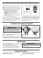
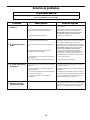
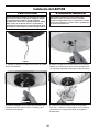
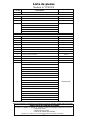
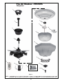
The Air Shadow ™ Fabric Shade Ceiling Fan WARNING: Support Directly From Building Structure Net Weight 13.15 kg (29 lbs) Model No. FP815FS OWNER’S MANUAL READ AND SAVE THESE INSTRUCTIONS For Canada, this fan must be secured directly to the building structure or ceiling joist. Don’t secure this fan to an outlet box. Important Safety Instructions WARNING: To avoid fire, shock and serious personal injury, follow these instructions. 1. Read your owner’s manual and safety information before installing your new fan. Review the accompanying assembly diagrams. 2. Before servicing or cleaning unit, switch power off at service panel and lock service panel disconnecting means to prevent power from being switched on accidentally. When the service disconnecting means cannot be locked, securely fasten a warning device, such as a tag, to the service panel. 3. Be careful of the fan and blades when cleaning, painting, or working near the fan. Always turn off the power to the ceiling fan before servicing. 4. Do not insert anything into the fan blades while the fan is operating. 5. Do not operate reversing switch until fan blades have come to a complete stop. Additional Safety Instructions 1. To avoid possible shock, be sure electricity is turned off at the fuse box before wiring, and do not operate fan without blades. 2. All wiring and installation procedures must satisfy National Electrical Codes (ANSI/ NFPA 70-1999) and Local Codes. The ceiling fan must be grounded as a precaution against possible electrical shock. Electrical installation should be made or approved by a licensed electrician. 3. The fan base must be securely mounted and capable of reliably supporting at least 50 lbs. (fan and accessories not to exceed 50 lbs. or 22.7 kgs.). See page 4 of owner’s manual for support requirements. Consult a qualified electrician if in doubt. WARNING: Mount only to an outlet box marked acceptable for fan support. 4. The fan must be mounted with the fan blades at least 7 feet from the floor to prevent accidental contact with the fan blades. 5. Follow the recommended instructions for the proper method of wiring your ceiling fan. If you do not have adequate electrical knowledge or experience, have your fan installed by licensed electrician. 6. Suitable for use with solid-state speed controls. WARNING: To reduce the risk of fire or electric shock, this fan should only be used with Fan Speed Control Part No. UC7067RC, manufactured by Rhine Electronic Co., Ltd. WARNING: TO REDUCE THE RISK OF SHOCK, THIS FAN MUST BE INSTALLED WITH AN ISOLATING WALL CONTROL/SWITCH. WARNING: This product is designed to use only those parts supplied with this product and/or accessories designated specifically for use with this product. Using parts and/or accessories not designated for use with this product could result in personal injury or property damage. WARNING: To reduce the risk of personal injury, do not bend the blade bracket (flange or blade holder) when installing the brackets, balancing the blades, or cleaning the fan. Do not insert foreign objects in between rotating fan blades. LIMITED LIFETIME WARRANTY Extends to the original purchaser of a Fanimation Fan 1. LIMITED LIFETIME MOTOR WARRANTY - If any part of your fan motor fails, due to a defect in materials or workmanship during the lifetime of the original purchaser, Fanimation will provide the replacement part free of charge, when the defective fan is returned to our national service center. Proof of purchase is required. Customer shall be responsible for all costs incurred in the removal or reinstallation and shipping of the product for repairs or replacement. 2. ONE YEAR MOTOR LABOR WARRANTY - If your fan motor fails at any time within one year from the original purchase, due to defects in materials or workmanship, labor to repair the motor will be provided free of charge at our national service center. Purchaser will be responsible for labor charges after this one-year period. Customer shall be responsible for all costs incurred in the removal or reinstallation and shipping of the product for repairs or replacement. 3. If any other part of your fan fails at any time within one year after original purchase, due to a defect in materials or workmanship, we will repair, or replace, at our option, the defective part free of charge for parts and labor performed at our national service center. 4. Because of varying climate conditions, this warranty does not cover changes in the finish, including rusting, pitting, corroding, tarnishing, or peeling. 5. This warranty is void and does not apply to damage from improper installation, neglect, accident, misuse, exposure to extremes of heat or humidity, or as a result of any modification to the original product. 6. All costs of removal and reinstallation of the fan are the sole responsibility of the owner of the fan and not the store that sold the fan or Fanimation. 7. Fanimation reserves the right to modify or discontinue any product at any time and may substitute any part under this warranty. 8. Under no circumstances may a fan be returned without prior authorization from Fanimation. The receipt of purchase must accompany authorized returns and must be sent freight prepaid to Fanimation. The fan to be returned must be properly packed to avoid damage in transit; Fanimation will not be responsible for any damage resulting from improper packaging. 9. It is understood that any repair or replacement is the exclusive remedy available from Fanimation. There is no other expressed or implied warranty. Fanimation hereby disclaims any and all implied warranties, including, but not limited to those of merchantability and fitness for a particular purpose to the extent permitted by law. Some states do not allow limitations on implied warranties. Fanimation will not be liable for incidental, consequential, or special damages arising out of or in conjunction with product use or performance, except as may otherwise be accorded by law. This warranty gives you special legal rights and you may also have other rights that vary from state to state. 10. A certain amount of wobble is normal and should not be considered a problem or a defect. Table of Contents Unpacking Instructions . . . . . . . . . . . . . . . . . . . . . . . . . . . . . . . . . . . . . . . . . . . . . . . . . . . . . . . . . . . . . . . . . . 3 Electrical and Structural Requirements . . . . . . . . . . . . . . . . . . . . . . . . . . . . . . . . . . . . . . . . . . . . . . . . . . . . . 4 How to Assemble Your Ceiling Fan . . . . . . . . . . . . . . . . . . . . . . . . . . . . . . . . . . . . . . . . . . . . . . . . . . . . . . . . . 4 How to Hang Your Ceiling Fan. . . . . . . . . . . . . . . . . . . . . . . . . . . . . . . . . . . . . . . . . . . . . . . . . . . . . . . . . . . . . 6 How to Wire Your Ceiling Fan . . . . . . . . . . . . . . . . . . . . . . . . . . . . . . . . . . . . . . . . . . . . . . . . . . . . . . . . . . . . . 7 How to Operate Your TR28 Remote Control . . . . . . . . . . . . . . . . . . . . . . . . . . . . . . . . . . . . . . . . . . . . . . . . . . 8 Installing the Canopy Housing . . . . . . . . . . . . . . . . . . . . . . . . . . . . . . . . . . . . . . . . . . . . . . . . . . . . . . . . . . . . 8 Maintenance . . . . . . . . . . . . . . . . . . . . . . . . . . . . . . . . . . . . . . . . . . . . . . . . . . . . . . . . . . . . . . . . . . . . . . . . . . . 8 Blade Cleaning . . . . . . . . . . . . . . . . . . . . . . . . . . . . . . . . . . . . . . . . . . . . . . . . . . . . . . . . . . . . . . . . . . . . . . . . . 8 Trouble Shooting. . . . . . . . . . . . . . . . . . . . . . . . . . . . . . . . . . . . . . . . . . . . . . . . . . . . . . . . . . . . . . . . . . . . . . . . 9 Installing the LK815 . . . . . . . . . . . . . . . . . . . . . . . . . . . . . . . . . . . . . . . . . . . . . . . . . . . . . . . . . . . . . . . . . . . . 10 Parts List . . . . . . . . . . . . . . . . . . . . . . . . . . . . . . . . . . . . . . . . . . . . . . . . . . . . . . . . . . . . . . . . . . . . . . . . . . . . . 12 Exploded-View Illustration . . . . . . . . . . . . . . . . . . . . . . . . . . . . . . . . . . . . . . . . . . . . . . . . . . . . . . . . . . . . . . . 13 This Manual is Designed to Make it as Easy as Possible for You to Assemble, Install, Operate, and Maintain Your Ceiling Fan Tools Needed for Assembly • One Phillips head screwdriver • One stepladder • One ¼“ blade screwdriver Materials • One wire stripper • Three wire connectors (supplied) Wiring outlet box and box connectors must be of type required by local code. The minimum wire would be a 3conductor (2-wire with ground) of the following size: ▲WARNING Before assembling your ceiling fan, refer to section on proper method of wiring your fan (page 4). If you feel you do not have enough wiring knowledge or experience, have your fan installed by a licensed electrician. Installed Wire Length Wire Size A.W.G. Up to 50 ft. 50 - 100 ft. 14 12 NOTE: Place the parts from the loose parts bags in a small container to keep them from being lost. If any parts are missing, contact your local retailer. Unpacking Instructions For your convenience, check-off each step. As each step is completed, place a check mark. This will ensure that all steps have been completed and will be helpful in finding your place should you be interrupted. ▲WARNING • Fan Motor assembly • Hardware bags: – Support Safety Cable bag – Two 5/32” threaded rods • Light Kit / Parts assembly – Two 5/32” lockwashers • Filigree – Two knurled knobs • Finial Base – Three 3/16” screws • Fabric Shade – Three 3/16” lockwashers • Inner Glass Bowl – Seven wire nuts • Internal Housing – Phillips screwdriver, 4” • Adapter Switch Cup – Rubber Washer • Hanger Bracket – Flat Washer • Downrod/Hanger Ball – Two hex nuts assembly – Finial nut • Ceiling Canopy – Six 5/32” screws • Motor Coupling Cover – Three 5/32” lockwashers • TR28 Hand-held Remote – Two wire nuts • Receiver Unit • Candelabra Bulbs (3) Do not install or use fan if any part is damaged or missing. This product is designed to use only those parts supplied with this product and/or any accessories designated specifically for use with this product by Fanimation. Substitution of parts or accessories not designated for use with this product by Fanimation could result in personal injury or property damage. Contact your retail store for missing or damaged parts. 1. Check to see that you have received the following parts: NOTE: If you are uncertain of part description, refer to exploded view illustration. (Figure 1, page 13) Hanger Bracket Ceiling Canopy Downrod/ Hanger Ball Assembly Motor Coupling Cover Receiver Unit Candelabra Bulbs 40W (3) Adapter Switch Cup Switch Cup Light Kit TR28 Hand-held Remote Finial Nut Internal Housing Filigree Finial Base Fan Motor Assembly Fabric Shade 3 Inner Glass Bowl Hardware Bag Electrical and Structural Requirements Your new ceiling fan will require a grounded electrical supply line of 120 volts AC, 60 Hz, 15 amp circuit. The outlet box must be securely anchored and capable of withstanding a load of at least 22.7 kgs (50 lbs). Figure 1 depicts different structural configurations that may be used for mounting the outlet box. Ceiling ▲WARNING Ceiling Joists To reduce the risk of fire, electrical shock, or personal injury, mount fan to outlet box marked acceptable for fan support of 22.7 kg (50 lbs) or less. Use screws supplied with outlet box. Most outlet boxes commonly used for support of light fixtures are not acceptable for fan support and may need to be replaced. Consult a qualified electrician if in doubt. 2˝ x 4˝ If your fan is to replace an existing light fixture, turn electricity off at the main fuse box at this time and remove the existing light fixture. Outlet Box Figure 1 ▲WARNING ▲WARNING Turning off wall switch is not sufficent. To avoid possible electrical shock, be sure electricity is turned off at the main fuse box before wiring. All wiring must be in accordance with National and Local codes and the ceiling fan must be properly grounded as a precaution against possible electrical shock. To avoid fire or shock, follow all wiring instructions carefully. Any electrical work not described in these instructions should be done or approved by a licensed electrician. How to Assemble Your Ceiling Fan 1. Prior to assembly, set aside and save the hardware bag(s) packed in the packing. 2. Remove the Hanger Ball by loosening the setscrew in the Hanger Ball until the ball falls freely down the Downrod. (Figure 1) Remove the Pin from the Downrod, then remove the Hanger Ball. Retain the Pin and Hanger Ball for reinstallation in Step 8. Pin Hanger Ball Setscrew 3. The fan comes with blue, black, gray and white 80˝ wires. Separate and untwist the wires. Route the wires through the Downrod. NOTE: You will be using either the 6˝ downrod supplied with your fan or an optional downrod purchased seperately. Figure 1 4. Position Fan/Motor Assembly on styrofoam pedestal, for ease of assembly. Motor Coupling Cover Downrod Support 5. Loosen the two setscrews in the Downrod Support. Align the Clevis Pin holes in the Downrod with the holes in the Downrod Support. Install the Clevis Pin and secure with the Hairpin Clip. (Figure 2) Be sure to push the straight leg of the hairpin clip through the hole near the end of the clevis pin until the curved portion of the hairpin clip snaps around the clevis pin. The hairpin clip must be properly installed to prevent the clevis pin from working loose. Pull on the Downrod to make sure the clevis pin is properly installed. (Figure 2) Hairpin Clip Clevis Pin Setscrew (2) Figure 2 4 How to Assemble Your Ceiling Fan (cont’d) 6. Route wires through opening in Motor Coupling Cover. Position Motor Coupling Cover on fan shown with open side facing down. (Figure 2) 7. Route wires through opening in Canopy. Position Canopy on fan shown with open side facing up. (Figure 3) 8. Reinstall the Hanger Ball (Figure 3) on the Downrod as follows. Route the three 80˝ wires through the Hanger Ball. Position the Pin through the two holes in the Downrod and align the Hanger Ball so the Pin is captured in the groove in the top of the Hanger Ball. Pull the Hanger Ball up tight against the pin. Securely tighten the setscrew in the Hanger Ball. A loose setscrew could create fan wobble. Downrod/Hanger Ball Assembly Ceiling Canopy Motor Coupling Cover ▲WARNING It is critical that the clevis pin in the downrod support is properly installed and the setscrews are securely tightened. Failure to verify that the pin and setscrews are properly installed could result in the fan falling. 9. While pulling up on the hanger ball, securely tighten the two 3/16-24 x 3/8˝ setscrews in the downrod support. (Figure 2) NOTE: The setscrews must be properly installed as described above, or fan-wobble could result. 10. Slide the Motor Coupling Cover down until it touches the top of the Housing. (Figure 3) 11. The fan comes with blue, black, gray and white leads. Before installing fan, measure up approximately 6-9 inches above top of Downrod/Hanger Ball Assembly. Cut off excess wire and strip back insulation ½˝ from end of wire. 12. You have now completed the assembly of your new ceiling fan. You can now proceed with the hanging and the electrical wiring of your fan. 5 Figure 3 How to Hang Your Ceiling Fan ▲WARNING To avoid possible electrical shock, be sure electricity is turned off at the main fuse box before hanging. NOTE: If you are not sure if the outlet box is grounded, contact a licensed electrician for advice, as it must be grounded for safe operation. ▲WARNING The fan must be hung with at least 7´ of clearance from floor to blades (Figure 1) No less than 7 ft ▲WARNING The outlet box must be securely anchored and capable of withstanding a load of at least 50 lbs. Hanger bracket must seat firmly against outlet box. If the outlet box is recessed, remove wallboard until bracket contacts box. If bracket and/or outlet box are not securely attached, the fan could wobble or fall. Figure 1 1. Using the 3⁄8˝ x 2˝ lag bolt and flat washer, attach safety cable to ceiling joist or wood structural member. The lag bolt will pass through the flat washer, safety cable loop, the junction box and into the building structure (Figure 2). You will first drill a ¼˝ pilot hole into the building structure to prevent splitting or cracking. Wood Member (2˝ x 4˝ Approx.) Floor Ceiling Joist 2. Securely attach the hanger bracket to ceiling junction box acceptable for ceiling support. NOTE: Ceiling support cable cannot be secured to junction box only, it must be directly secured to ceiling joist or structural member using the ⅜˝ x 2˝ lag bolt and flat washer. (Figure 2). Junction Box Ceiling Ceiling Support Cable 3. Make sure the electrical supply wires, including the hanger bracket grounding wire and safety cable are pulled through the downrod, between the hanger bracket and the junction box so that electrical connections can be made later. Hanger Bracket Figure 2 4. Carefully lift the fan and seat the downrod/hanger ball assembly on the hanger bracket that was just attached to the ceiling joist. Be sure the groove in the ball is lined up with tab on the hanger bracket. (Figure 3) 5. Attach the safety cable to ceiling support cable. Slide cable clamp onto safety cable (from fan). Place the end of cable through the loop of ceiling support cable. Pull as much cable through loop as possible. Feed end of cable into clamp hole and firmly tighten screw (Figure 3). Cut off excess safety cable. Attach Safety Cable to Ceiling Support Cable ▲WARNING Tab NOTE: Supply wires and fan wires omitted for clarity Failure to seat tab in groove could cause damage to electrical wires and possible shock or fire hazard. ▲WARNING To avoid possible shock, do not pinch wires between the downrod/hanger ball assembly and the hanger bracket. 6 Downrod/Hanger Ball Assembly Figure 3 How to Wire Your Ceiling Fan If you feel that you do not have enough electrical wiring knowledge or experience, have your fan installed by a licensed electrician. ▲WARNING To avoid possible electrical shock, be sure electricity is turned off at the main fuse box before wiring. NOTE: If you are not sure if the outlet box is grounded, contact a licensed electrician for advice, as it must be grounded for safe operation. 1. Setting the Code: The remote unit has 16 different code combinations. It may be necessary to test a couple frequency code settings to improve signal reception and/or eliminate interference from other remote control household items. Multiple fans should have different code settings to allow independent fan control. To set the code, perform these steps. • Transmitter: remove battery cover. Press firmly below arrow and slide battery cover off. Slide code switches to your choice of up or down position. Factory setting is all up. Do not use this position. With a small screwdriver or ball point pen slide firmly up or down (Figure 1a). Replace battery cover on the transmitter. • Receiver: Slide code switches to the same positions as set on your transmitter (Figure 1b). Remote Transmitter Unit Detail Receiver Unit Detail Figure 1a Figure 1b NOTE: If fan or supply wires are different colors than indicated, have this unit installed by a qualified electrician. Ceiling Bracket (Open End) Receiver Unit NOTE: Receiver wires omitted for clarity. Figure 2 2. Installing Receiver in Hanger Bracket: • Slide remote Receiver into the Hanger Bracket (Figure 2). • Connect wires as indicated: (Figure 3) • Green Hanger Bracket & Hanger Ball wires to BARE (ground) wire. • BLACK Receiver Unit wire (AC IN L) to BLACK supply wire. • WHITE Receiver Unit wire (AC IN N). to WHITE supply wire. • WHITE Receiver Unit wire (TO MOTOR N) to WHITE fan wire. • BLACK Receiver Unit wire (TO MOTOR L) to BLACK fan wire. • BLUE Receiver Unit wire (FOR LIGHT DOWN) to BLUE light wire. • GRAY Receiver Unit wire (REVERSE MODULE) to GRAY wire. • Position all connected wires and receiver antenna to allow installation of ceiling canopy. • Using canopy screws threaded into the hanger bracket install ceiling canopy. (see page 8) GRN from hanger ball GRN from bracket GRN or BARE GROUND WH-TO MOTOR N BLK-TO MOTOR L GRAY-REVERSE MODULE BLUE-FOR LIGHT DOWN WH-AC IN N BL-AC IN L BLK-ANT 120 VAC SUPPLY (User Supplied) Figure 3 ▲WARNING Check to see that all connections are tight, including ground, and that no bare wire is visible at the wire connectors, except for the ground wire. Do not operate fan until the blades is in place. Noise and fan damage could result. 3. After making the wire connections, the wires should be spread apart, turned upward and pushed carefully up into the outlet box, with the grounded conductor and the equipment-grounding conductor on one side of the outlet box and the ungrounded conductor on the other side of the outlet box. 7 How to Operate Your TR28 Remote Control 1. Operating & Using Remote Transmitter (Figure 1): Install two piece of 3 volt battery (If not using for long periods of time, remove battery to prevent damage to transmitter). Store the transmitter away from excess heat or humidity. • HI Push Button – high fan speed • MED Push Button – medium fan speed • LOW Push Button – low fan speed • Push Button – fan off • REV Push Button – toggles between air upflow and air downflow • *Demo Push Button – on/off auto demo mode • Light Push Button – on/off and brightness control for optional down light. To control either light hold down key to increase or decrease brightness. Tap key quickly to turn light on or off. The light keys have auto resume and will stay at the same brightness as the last time it was turned off. 3V, CR2032 BATTERY 2 PCS Figure 1 *Demo mode is initiated by pressing the Demo button on the remote, lights will flash 3 times. Fan runs for 2½ minutes then shuts off for ½ minute. The 2 ½ / ½ minute run cycles continue until any other button is pressed on the remote control. Installing the Canopy Housing NOTE: This step is applicable after the neccessary wiring is completed. (see page 7) ▲WARNING To avoid possible fire or shock, make sure that the electrical wires are completely inside the canopy housing and not pinched between the housing and the ceiling. 1. Screw in two threaded rods into the Hanger Bracket (Figure 1a). NOTE: The threaded rods in the hanger bracket serve as guides for easier installation. NOTE: Supply wires and fan wires omitted for clarity. Figure 1a Figure 1b 2. Securely attach the Canopy Housing to the Hanger Bracket using the external lockwashers and knurled knobs supplied with your fan (Figure 1b). Maintenance Periodic cleaning of your new ceiling fan is the only maintenance that is needed. When cleaning, use only a soft brush or lint free cloth to avoid scratching the finish. Abrasive cleaning agents are not required and should be avoided to prevent damage to finish. CAUTION Do not use water when cleaning your ceiling fan. It could damage the motor or the finish and create the possibility of electrical shock. Blade Cleaning Avoid using water, cleansers, or harsh rags, which can warp and ruin the blade and the finish. Periodic light dusting of the blades is recommended. A feather duster will work best. 8 Trouble Shooting ▲WARNING For your own safety turn off power at fuse box or circuit breaker before trouble shooting your fan. Trouble 1. FAN WILL NOT START Probable Cause Suggested Remedy 1. Fuse or circuit breaker blown. 1. Check main and branch circuit fuses or circuit breakers. 2. Loose power line connections to the fan, or loose switch wire connections in the switch housing. 2. Check line wire connections to fan and switch wire connections in the switch housings. CAUTION: Make sure main power is turned off ! 3. Dead battery in remote control. 3. Replace with fresh battery. 1. Loose screws in motor housing. 1. Check to make sure all screws in motor housing are snug (not over-tight). 2. Wire connectors inside housing rattling. 2. Check to make sure wire connectors in switch housing are not rattling against each other or against the interior wall of the switch housing. CAUTION: Make sure main power is turned off ! 2. FAN SOUNDS NOISY 3. FAN WOBBLES EXCESSIVELY 3. Motor noise caused by solid state variable speed control. 3. Some fan motors are sensitive to signals from solid-state variable speed controls. Solid-state controls are not recommended, choose an alternative control method. 4. Screws holding blades to blade holders are loose. 4. Tighten screws securely. 5. Lower housing support set screw loose. 5. Tighten set screw securely. 1. Setscrew in downrod support is loose. 1. Tighten both setscrews securely in downrod support. 2. Setscrew in downrod/hanger ball assembly is loose. 2. Tighten the setscrew in the downrod/hanger ball assembly. 3. Screws securing fan blade holders to motor hub are loose. 3. Check to be sure screws which attach the fan blade holders to the flywheel are tight. 4. Hanger bracket and/or ceiling outlet box is not securely fastened. 4. Tighten the hanger bracket screws to the outlet box, and secure outlet box. 1. If possible, consider using a longer downrod. For example, use a 12” downrod instead of the 6” downrod that comes with your fan. 4. NOT ENOUGH AIR MOVEMENT 9 Installing the LK815OB CAUTION ▲WARNING Turning off wall switch is not sufficent. To avoid possible electrical shock, be sure electricity is turned off at the main fuse box before wiring. All wiring must be in accordance with National and Local codes and the ceiling fan must be properly grounded as a precaution against possible electrical shock. To avoid fire or shock, follow all wiring instructions carefully. Any electrical work not described in these instructions should be done or approved by a licensed electrician. Figure 1 Figure 2 1. Locate accessory mounting plate on bottom of fan. 2. Mount internal housing unit on accessory mounting plate with 3 screws provided, in bag labeled “Housing to Motor Assembly”. Figure 3 Figure 4 3. Install switch cup adapter on the internal housing unit with 3 screws and 3 lockwashers provided. 4. Locate white and blue wires labeled “FOR LIGHT”. Connect white-to-white and blue-to-black wires with wire nuts supplied. 10 Installing the LK815OB (cont’d) Figure 5 Figure 6 5. Install light fixture to adapter with 3 screws provided. 6. Install three-40 watt candelabra bulbs (included). Figure 7 Figure 8 7. Install glass bowl, rubber washer, flat washer and two nuts provided, do not over-tighten. 8. Assemble fabric shade, filigree and finial base. Figure 9 9. Install finial nut, do not over-tighten. 11 Parts List Model #FP815FS Ref. # Description Part # Retractable Fan Assembly – Fabric Shade FP815FS FAN MOTOR ASSEMBLY — MAR20CY 5 Retractable Fan Motor Assembly 13 Control Receiver 14 Hand-held Remote — RECCAN57DEMO TR28 Support Cable Bag Containing: Ceiling Support Cable Cable Clamp Flat Washer Lag Bolt, 3/8“ x 2” FABRIC SHADE LIGHT KIT ASSEMBLY — LK815OB 6 Internal Housing with brackets AP81572WH 7 Adapter Switch Cup P81085BL 8 Switch Cup Light Kit AP81556WH 8A Candelabra Bulbs, 40W (3) 1 Hanger Bracket Assembly APG610BL 2 Ball/Downrod Assembly ADR1x6OB 3 Ceiling Canopy PG165OB 4 Motor Coupling Cover P81090OB 9 Frosted Glass Bowl P81521 10 Fabric Shade P81516 11 Filigree P81530OB Finial Base P81510OB 12 Hardware(s) Bag Containing: Rubber Washer Flat Washer Hex Nut (2) Wire Nut (7) Finial Nut Canopy Hardware Bag Containing: 8 5/32 “ Threaded Rods (2) 5/32 “ External Lockwasher (2) HDWLK815OB Knurled Knobs (2) Housing Mount Hardware Bag Containing: 3/16 “ Pan Head Screw (3) 3/16 “ External Lockwasher (3) Phillips Screwdriver, 4” Adapter Mounting Hardware Bag Containing: 5/32“ Pan Head Screw (6) 5/32 “ External Lockwasher (3) Wire Nut, P2 (2) Before discarding packaging materials, be certain all parts have been removed How To Order Parts Contact your retail store for repair parts. When ordering repair parts, always give the following information. 12 • Part Number • Part Description • Fan Model Number The Air Shadow Fan FP815FS Exploded-View 6 1 7 2 8 8A 3 9 4 10 5 11 14 12 13 8 8 ref Figure 1 NOTE: The illustration shown is not to scale or its actual configuration may vary. 13 Copyright 2011 Fanimation 10983 Bennett Parkway Zionsville, IN 46077 (888) 567-2055 FAX (866) 482-5215 Outside U.S. call (317) 733-4113 Visit Our Website www.fanimation.com 2011/01 The Air Shadow ™ Ventilador de techo con pantalla de tela ADVERTENCIA: Soporte directo desde la estructura del edificio Peso neto 29 lb (13.15kg) Modelo N.º FP815FS MANUAL DEL PROPIETARIO LEA Y GUARDE ESTAS INSTRUCCIONES En Canadá, este ventilador debe ser fijado directamente a la estructura del edificio o de la viga del techo. No fije este ventilador en una caja de distribución eléctrica. Instrucciones de seguridad importantes ADVERTENCIA: Siga estas instrucciones para prevenir incendios, descargas eléctricas y lesiones personales graves. 1. Lea el manual del propietario y la información de seguridad antes de instalar su nuevo ventilador. Observe los diagramas de ensamblaje adjuntos. 2. Antes de llevar a cabo el mantenimiento o la limpieza de la unidad, desconecte la electricidad en el panel de servicio y bloquee los medios de desconexión del mismo para evitar que se active accidentalmente. Si no se pueden bloquear los medios de desconexión del servicio, coloque un dispositivo de advertencia, como una etiqueta, en el panel de servicio. 3. Tenga cuidado con la estructura y las aspas del ventilador cuando limpie, pinte o trabaje cerca del mismo. Desconecte siempre la electricidad del ventilador de techo antes de llevar a cabo el mantenimiento. 4. No coloque nada en las aspas del ventilador cuando éste se encuentra en funcionamiento. 5. No accione el conmutador inversor hasta que las aspas del ventilador se hayan detenido por completo. Instrucciones de seguridad adicionales 1. Para evitar posibles descargas eléctricas, asegúrese de que la electricidad esté desconectada en la caja de fusibles antes de realizar la instalación eléctrica, y no haga funcionar el ventilador sin las aspas. 2. Todos los procedimientos de conexión eléctrica e instalación deben cumplir con los Códigos eléctricos nacionales (ANSI/NFPA 70-1999) y Códigos locales. El ventilador de techo debe estar conectado a tierra a fin de prevenir posibles descargas eléctricas. La instalación eléctrica debe ser llevada a cabo o aprobada por un electricista autorizado. 3. Se debe fijar bien la base del ventilador; ésta debe ser capaz de soportar sin problemas al menos 22,7 kg (50 lb). Consulte la página 18 del manual del propietario para ver los requisitos de soporte. Si tiene dudas, consulte a un electricista calificado. ADVERTENCIA: Monte a una caja de salida aceptable para apoyo de los aficionados 4. Las aspas del ventilador deben instalarse por lo menos a 2 m (7 pies) del suelo, a fin de evitar un contacto accidental con las mismas. 5. Siga las recomendaciones sobre el método correcto de instalación eléctrica de su ventilador de techo. Si no posee la experiencia o los conocimientos eléctricos adecuados, contrate a un electricista autorizado para instalar el ventilador. 6. Apto para usar con controles de velocidad de estado sólido. ADVERTENCIA: Para reducir el riesgo de incendios o descargas eléctricas, este ventilador solo debería ser utilizado con la pieza de control de velocidad del ventilador Nº UC7067RY fabricada por Rhine Electronic Co., Ltd. ADVERTENCIA: PARA REDUCIR EL RIESGO DE DESCARGAS ELÉCTRICAS, ESTE VENTILADOR SE DEBE INSTALAR CON UN CONTROL/INTERRUPTOR DE PARED AISLADO. ADVERTENCIA: Este producto está diseñado para ser usado sólo con las piezas suministradas o los accesorios indicados específicamente para el mismo. Si utiliza piezas o accesorios que no están indicados para su uso con este producto, podría sufrir lesiones personales o dañar el ventilador. ADVERTENCIA: Este producto está diseñado para ser usado sólo con las piezas suministradas o los accesorios indicados específicamente para el mismo. Si utiliza piezas o accesorios que no están indicados para su uso con este producto, podría sufrir lesiones personales o dañar el ventilador. ADVERTENCIA: Para reducir el riesgo de lesiones personales, no doble los soportes de las aspas (borde o soporte de aspas) al instalar los soportes, balancear las aspas o limpiar el ventilador. No coloque objetos extraños entre las aspas del ventilador en funcionamiento. GARANTÍA LIMITADA DE POR VIDA Se extiende al comprador original de un ventilador Fanimation 1. GARANTÍA LIMITADA DE POR VIDA DEL MOTOR - Si se produjera una falla en alguna de las partes del motor de su ventilador debido a un defecto en los materiales o en la fabricación durante el tiempo de vida del comprador original, Fanimation proporcionará la pieza de repuesto sin cargo una vez que el ventilador defectuoso sea devuelto a nuestro centro de servicios nacional. Se requiere comprobante de venta. El cliente se hará responsable de todos los gastos de remoción o reinstalación y envío del producto para reparaciones o sustitución. 2. GARANTÍA DE MANO DE OBRA DEL MOTOR POR UN AÑO - Si el motor de su ventilador fallara antes de cumplirse un año a partir del momento de su compra original debido a defectos en los materiales o en la fabricación, se le efectuará la reparación del mismo sin cargo en nuestro centro de servicios nacional. El comprador se hará responsable de los gastos de mano de obra luego del período de un año. El cliente se hará responsable de todos los gastos de remoción o reinstalación y envío del producto para reparaciones o sustitución. 3. Si otra pieza del ventilador fallara dentro del período de un año a partir de la fecha de compra original debido a un defecto en los materiales o en la fabricación, repararemos o sustituiremos, según creamos conveniente, la pieza defectuosa sin cargo alguno en nuestro centro de servicios nacional. 4. Debido a las diversas condiciones climáticas, esta garantía no cubre cambios en la terminación, incluidos oxidación, corrosión, falta de brillo o peladuras. 5. Esta garantía es nula y no se aplica a daños por instalación incorrecta, negligencia, accidentes, uso indebido, exposición al calor o a la humedad en exceso, o como resultado de cualquier modificación realizada al producto original. 6. Todos los gastos de remoción y reinstalación del ventilador son responsabilidad exclusiva del propietario, y no de la tienda que vendió el ventilador ni de Fanimation. 7. Fanimation se reserva el derecho de modificar o discontinuar un producto en cualquier momento, o sustituir cualquier pieza según lo establecido por esta garantía. 8. En ningún caso se podrá devolver un ventilador sin previa autorización por parte de Fanimation. Las devoluciones autorizadas deberán ir acompañadas del recibo de venta y deberán enviarse a Fanimation, previo pago del flete. El ventilador que se devuelva deberá estar embalado en forma adecuada a fin de evitar daños durante el transporte. Fanimation no se hará responsable de los daños que resulten del embalaje incorrecto del producto. 9. Se entiende que las reparaciones y las sustituciones son el único recurso disponible de Fanimation. No existe ninguna otra garantía expresa o implícita. Por la presente, Fanimation niega todas las garantías implícitas, que incluyen, entre otras, la comerciabilidad y la aptitud para determinado fin hasta donde la ley lo permita. Algunos estados no permiten limitaciones sobre las garantías implícitas. Fanimation no se hará responsable por daños accidentales, resultantes o especiales derivados del uso o el rendimiento del producto o en conjunción con éste, excepto en los casos en los que la ley así lo disponga. Esta garantía le otorga derechos legales especiales y es posible que también goce de otros derechos que pueden variar según el estado. 10. Es normal que se produzca un cierto movimiento oscilante y esto no debe considerarse un problema o defecto. Tabla de contenidos Instrucciones para el desempaque . . . . . . . . . . . . . . . . . . . . . . . . . . . . . . . . . . . . . . . . . . . . . . . . . . . . . . . . . . . . 17 Uso eficiente de la energía en ventiladores de techo . . . . . . . . . . . . . . . . . . . . . . . . . . . . . . . . . . . . . . . . . . . . . . . 18 Cómo ensamblar el ventilador de techo . . . . . . . . . . . . . . . . . . . . . . . . . . . . . . . . . . . . . . . . . . . . . . . . . . . . . . . . .18 Cómo colgar el ventilador de techo . . . . . . . . . . . . . . . . . . . . . . . . . . . . . . . . . . . . . . . . . . . . . . . . . . . . . . . . . . . . 20 Cómo realizar la instalación eléctrica del ventilador de techo . . . . . . . . . . . . . . . . . . . . . . . . . . . . . . . . . . . . . . . . 21 Cómo utilizar su mando a distancia TR28 . . . . . . . . . . . . . . . . . . . . . . . . . . . . . . . . . . . . . . . . . . . . . . . . . . . . . . . 22 IInstalación de la cubierta del capuchón . . . . . . . . . . . . . . . . . . . . . . . . . . . . . . . . . . . . . . . . . . . . . . . . . . . . . . . . 22 Mantenimiento . . . . . . . . . . . . . . . . . . . . . . . . . . . . . . . . . . . . . . . . . . . . . . . . . . . . . . . . . . . . . . . . . . . . . . . . . . . 22 Limpieza de las aspas . . . . . . . . . . . . . . . . . . . . . . . . . . . . . . . . . . . . . . . . . . . . . . . . . . . . . . . . . . . . . . . . . . . . . 22 Solución de problemas . . . . . . . . . . . . . . . . . . . . . . . . . . . . . . . . . . . . . . . . . . . . . . . . . . . . . . . . . . . . . . . . . . . . . 23 Instalación del LK815 . . . . . . . . . . . . . . . . . . . . . . . . . . . . . . . . . . . . . . . . . . . . . . . . . . . . . . . . . . . . . . . . . . . . . 24 Lista de piezas . . . . . . . . . . . . . . . . . . . . . . . . . . . . . . . . . . . . . . . . . . . . . . . . . . . . . . . . . . . . . . . . . . . . . . . . . . . 26 Ilustración del despiece . . . . . . . . . . . . . . . . . . . . . . . . . . . . . . . . . . . . . . . . . . . . . . . . . . . . . . . . . . . . . . . . . . . . 27 Este manual está diseñado para facilitar al máximo el ensamblaje, la instalación, el funcionamiento y el mantenimiento de su ventilador de techo. Herramientas necesarias para el ensamblaje • Destornillador Phillips • Escalera de tijera • Destornillador de ¼˝ Materiales La caja de distribución eléctrica y los conectores de la caja deben ser del tipo requerido por el código local. El cable más pequeño debe ser un cable de tres conductores (de dos conductores con conexión a tierra) del siguiente tamaño: tamaño del cable según el A.W.G. longitud del cable instalado (Calibre de Alambre Estadounidense) hasta 15,2 m (50 pies) 14 de 15,2 a 30,5 m (50 a 100 pies) 12 • Pelacables • Tres conectores de cables (incluidos) ADVERTENCIA Antes de ensamblar el ventilador de techo, consulte la sección sobre el método correcto de instalación eléctrica del ventilador (página 18). Si siente que no posee la experiencia o los conocimientos eléctricos necesarios, contrate a un electricista autorizado para instalar el ventilador. NOTA: coloque las piezas de las bolsas de piezas individuales en un contenedor pequeño para evitar que se extravíen. Si faltan piezas, póngase en contacto con su proveedor local. Instrucciones para el desempaque Para su comodidad, marque cada uno de los pasos. A medida que completa cada paso, coloque una marca de verificación. Con esto se asegurará de completar todos los pasos y podrá saber desde dónde retomar si fuera interrumpido. ADVERTENCIA No instale ni utilice el ventilador si falta alguna pieza o si hay piezas dañadas. Este producto está diseñado para ser usado sólo con las piezas suministradas o los accesorios indicados por Fanimation específicamente para el mismo. La sustitución de piezas o accesorios no designados por Fanimation para usar con este producto podría ocasionar lesiones personales o daños en el ventilador. Póngase en contacto con su tienda si faltan piezas o hay piezas dañadas. 1. Verifique que haya recibido las siguientes piezas: NOTA: Si no está seguro de la descripción de una pieza, consulte la ilustración del despiece. (Figura 1, página 27) Unidad del soporte de suspensión Capuchón de techo • Unidad del motor del ventilador • Bolsa de accesorios: • Montaje de las piezas / Kit de luz – Dos varillas roscadas de 5/32” • Filigrana – Dos arandelas de 5/32” • Base del sombrerete – Dos pomos moleteados • Pantalla de tela – Tres tornillos de 3/16” • Tulipa de cristal interior – Tres arandelas de 3/16” • Carcasa interior – Siete tuercas para alambre • Carcasa interna – Destornillador Phillips de 4” • Cubierta del interruptor del – Arandela de goma adaptador – Dos tuercas hexagonales • Unidad del soporte de suspensión – Tuerca de sombrerete • Unidad del barral/de la interna – Seis tornillos de 5/32” • Capuchón de techo – Tres arandelas de 5/32” • Cubierta de unión del motor – Dos tuercas para alambre • TR28 De mano a distancia • Unidad del receptor • Bombillas tipo candelabro (3) Unidad del barral/de la semiesfera Cubierta de unión del motor Unidad del receptor Bombillas tipo candelabro 40Vatios (3) Cubierta del interruptor del adaptador Montaje de las piezas / Kit de luz TR28 De mano a distancia Tuerca de sombrerete Carcasa interna Filigrana Base del sombrerete Unidad del motor del ventilador Pantalla de tela 17 Tulipa de cristal interior Bolsa de accesorios Requisitos eléctricos y estructurales Su nuevo ventilador de techo requiere una línea de suministro eléctrico con conexión a tierra de 120 voltios de CA, 60 Hz, circuito de 15 amperios. La caja de distribución eléctrica debe estar bien asegurada y debe ser capaz de soportar una carga de, al menos, 22,7 kg (50 lb). La Figura 1 muestra diversas configuraciones estructurales que podrían utilizarse para montar la caja de distribución eléctrica. Techo ▲ADVERTENCIA Vigas del techo Para reducir el riesgo de incendios, descargas eléctricas o lesiones personales, fije el ventilador a la caja de distribución eléctrica marcada como aceptable para un peso de 22,7 kg (50 lb) o menos. Utilice los tornillos suministrados con la caja de distribución eléctrica. La mayoría de las cajas de distribución eléctricas que comúnmente se utilizan como soporte de lámparas no sirven como soporte de ventiladores y es posible que deban reemplazarse. Consulte a un electricista calificado si tiene dudas. 5 x 10 cm (2˝ x 4˝) Caja de distribución eléctrica Figura 1 Si el ventilador irá en lugar de una lámpara existente, desconecte la electricidad de la caja de fusibles principal y quite la lámpara. ▲ADVERTENCIA ▲ADVERTENCIA A fin de evitar incendios o descargas eléctricas, siga con cuidado todas las instrucciones de instalación eléctrica. Cualquier trabajo eléctrico que no se describa en estas instrucciones deberá ser realizado o aprobado por un electricista autorizado. Apagar el interruptor de pared no es suficiente. Para evitar posibles descargas eléctricas, asegúrese de que la electricidad esté desconectada de la caja de fusibles principal antes de realizar la instalación eléctrica. Toda instalación eléctrica debe cumplir con los Códigos Nacionales y Locales y el ventilador de techo debe tener la conexión a tierra adecuada como forma de precaución ante posibles descargas eléctricas. Cómo ensamblar el ventilador de techo 1. Antes de realizar el ensamblaje, separe y guarde las bolsas de accesorios en el empaque. 2. Afloje el tornillo de fijación de la semiesfera para lograr que ésta pueda desplazarse libremente por el barral. Retire el pasador del barral y luego extraiga la semiesfera. Conserve el pasador y la semiesfera para su reinstalación en el Paso 8 (Figura 1). 3. El ventilador viene con cables de 80˝ de color azul, negro y blanco. Separe y desenrosque los tres cables . Pase los cables a través del barral. NOTA: Podrá utilizar el barral de 15,24 cm (6”) que viene con el ventilador o un barral opcional comprado por separado. 4. Coloque la unidad del motor/ventilador sobre la espuma de poliestireno para facilitar su montaje. 5. Afloje los dos tornillos de fijación del soporte del barral. Alinee los orificios del pasador en el barral con los orificios del soporte del mismo. Instale la clavija de horquilla y asegúrela con la pinza de horquilla. Asegúrese de que presiona el extremo derecho de la pinza de horquilla a través del orificio cercano al final de la clavija de horquilla hasta que la parte curva de la misma se cierre sobre la clavija de horquilla. Debe instalar correctamente la pinza de horquilla para evitar que se afloje la clavija de horquilla. Tire de la varilla interior para asegurarse de la clavija de horquilla esté bien instalada. (Figura 2) 18 Pasador Tornillo de fijación Bola para colgar Figura 1 Cubierta de unión del motor Pasador de horquilla Unidad del barral/de la semiesfera pasador de horquilla Tornillo de fijación (2) Figura 2 Cómo ensamblar el ventilador de techo (Cont.) 6. Introduzca los cables a través de la apertura en la carcasa de acoplamiento del motor. Posicione la carcasa de acoplamiento del motor sobre el ventilador con la parte abierta mirando hacia abajo. (Figura 2) 7. Introduzca a través de la apertura de la abierta mirando hacia arriba. (Figura 3) Unidad del barral/de la semiesfera Capuchón de techo 8. Vuelva a colocar la semiesfera en el barral como se indica a continuación. Pase los tres cables de 2.03 m (80˝) a través de la semiesfera. Pase el pasador a través de los dos orificios en el barral y alinee la semiesfera de modo que el pasador quede atrapado en la ranura de la parte superior de la misma. Empuje la semiesfera hacia arriba, bien ajustada contra el pasador. Ajuste firmemente el tornillo de fijación en la semiesfera. Si el tornillo de fijación está flojo, podría provocar oscilación del ventilador. (Figura 3) Cubierta de unión del motor ▲ADVERTENCIA Es de suma importancia que el tornillo Clevis en el soporte del barral esté colocado correctamente y que los tornillos de fijación y las tuercas estén bien ajustados. Si el tornillo Clevis, las tuercas, el pasador de horquilla y los tornillos de fijación no están correctamente colocados, el ventilador podría caerse. 9. Mientras sostiene arriba la bola colgante, fije correctamente los dos tornillos de presión de 3/16-24 x 3/8˝ en el soporte de la varilla interior. (Figura 2) NOTA: Debe colocar adecuadamente los tornillos de presión tal y como se describe anteriormente, ya que de lo contrario podría provocar que se tambalee el ventilador. 10. Deslice la cubierta del motor de acoplamiento abajo hasta que toque la parte superior de la carcasa. (Figura 3) 11. El ventilador viene con cables azul, negros, gris y blanc Antes de instalar el ventilador, mida aproximadamente hasta 6-9 pulgadas por encima de la unidad de la bola colgante/varilla interior. Corte el cable restante y quite media pulgada de protección en el extremo del cable. 12. Ha completado el montaje de su nuevo ventilador de techo. Ahora puede proceder con la operación de colgado y cableado eléctrico de su ventilador. 19 Figura 3 Cómo colgar el ventilador de techo ADVERTENCIA Para evitar una posible descarga eléctrica, asegúrese de cortar la alimentación eléctrica de la caja de fusibles principal antes de colgar el ventilador. NOTA: Si no está seguro de si la caja de salida tiene conexión a tierra, pida consejo a un electricista certificado, ya que debe tener conexión a tierra para un funcionamiento seguro. ADVERTENCIA No menos de 2,13 m Debe colgar el ventilador a una distancia mínima de 2,13 m desde las aspas hasta el piso. (Figura. 1) ADVERTENCIA La caja de salida debe estar bien asegurada. La abrazadera para colgar debe estar bien asentada contra la caja de salida. Si la caja de salida está empotrada, retire el panel hasta que la abrazadera haga contacto con la caja. Si la abrazadera y/o la caja de salida no están bien aseguradas, el ventilador podría tambalearse o caerse. Figure 1 Miembro de madera (5 x 10 cm [2”x 4”] aprox.) 1. Perfore un orificio de 1/4” en la estructura del edificio para evitar grietas con la instalación del tornillo de intervalo. Utilice el tornillo de intervalo de 3/8”x 2” y la arandela plana para fijar el cable de seguridad a la viga del techo o a la estructura de madera. Dicho tornillo pasará a través de arandela plana, la presilla del cable de seguridad y se fijará en la estructura del edificio. (Figura. 2) EI Piso Viga del techo Techo Caja de conexiones 2. Fije adecuadamente el soporte colgante a la caja de empalme del techo que sea aceptable para el soporte del techo. Soporte de suspensión Cable de soporte para techo Figura 2 NOTA: el cable de soporte para techo no se puede asegurar solamente a la caja de conexiones; se debe asegurar directamente a la viga de techo o miembro estructural con el tornillo de cabeza cuadrada de ⅜˝x2˝ y la arandela plana. (Figura 2) 3. Asegúrese de que los cables de suministro eléctrico, incluido el cable de conexión a tierra del soporte de suspensión y el cable de seguridad, hayan atravesado el barral, entre el soporte de suspensión y la caja de conexiones, de modo que más tarde se pueda realizar la instalación eléctrica. Fije el cable de seguridad al cable de soporte para techo 4. Levante cuidadosamente el ventilador y coloque el ensamble de la bola para colgar/varilla en la abrazadera para colgar que acaba de fijar a la caja de salida. Asegúrese de que la ranura de la bola esté alineada con la lengüeta de la abrazadera para colgar. (Figura. 3) Pestaña NOTA: se omiten los cables de suministro y los cables del ventilador para mayor claridad. ADVERTENCIA Unidad del barral/ de la semiesfera Figura 3 ADVERTENCIA Si no coloca la lengüeta en la ranura, podrían dañarse los cables eléctricos y podrían ocurrir incendios o descargas eléctricas. Para evitar una posible descarga eléctrica, no apriete los cables entre el ensamble de la bola para colgar y la abrazadera para colgar. 20 Cómo realizar la instalación eléctrica del ventilador de techo Si considera que no cuenta con la experiencia o los conocimientos eléctricos necesarios, contrate a un electricista autorizado para instalar el ventilador. ADVERTENCIA Detalle del transmisor remoto Para evitar posibles descargas eléctricas, asegúrese de que la electricidad esté desconectada en la caja de fusibles principal antes de realizar la instalación eléctrica. NOTA: Si no está seguro de si la caja de distribución eléctrica tiene conexión a tierra, pida asesoramiento a un electricista autorizado, ya que la conexión a tierra es fundamental para un funcionamiento seguro. Detalle de la unidad del receptor Batería de 3V 1. Configuración del código: La unidad del control remoto cuenta con 16 combinaciones de código diferentes. Para evitar posibles interferencias desde o hacia otras unidades de control remoto como la de apertura de puertas del garaje, la alarma del auto o sistemas de seguridad, simplemente cambie la combinación del código en su transmisor y receptor. Para configurar el código, siga los siguientes pasos. Figura 1a Figura 1b NOTA: Si los cables de suministro o del ventilador son de colores para que realice la instalación. Techo • Transmisor: retire la cubierta de la batería. Presione firmemente la flecha que se encuentra debajo y deslice para retirar la cubierta de la batería. Seleccione su opción deslizando los interruptores de código hacia arriba o hacia abajo. La configuración de fábrica es en la posición superior. No utilice esta posición. Con un destornillador pequeño o con una lapicera deslice firmemente hacia arriba o hacia abajo (Figura 1a).Vuelva a colocar la cubierta de la batería en el transmisor. Soporte (extremo abierto) 3. Cuando haya conectado los cables, colóquelos de forma extendida y empújelo hacia arriba para colocarlos dentro de la caja de distribución eléctrica. Coloque el conductor con toma de tierra y el conductor del equipo con toma de tierra a un lado de la caja de distribución, colocando el conductor sin toma de corriente al otro lado de la misma. 21 CABLE DE CONEXIÓN A TIERRA DESNUDO o VERDE GRN desde el soporte • Receptor: Deslice los interruptores de código a las mismas posiciones que en el transmisor (Figura 1b). 2. Instalación del receptor en el soporte colgante: • Deslice el receptor remoto en el soporte colgante. (Figura 2) • Conecte los cables como se indica: (Figura 3) • El soporte colgante verde y los cables de la bola colgante van al cable desnudo (tierra). • Cable NEGRO de la unidad del receptor (CA EN L) al cable de suministro NEGRO. • Cable BLANCO de la unidad del receptor (CA EN N) al cable de suministro BLANCO. • Cable BLANCO de la unidad del receptor (AL MOTOR N) al cable BLANCO del ventilador. • Cable NEGRO de la unidad del receptor (AL MOTOR L) al cable NEGRO del ventilador • Cable AZUL de la unidad del receptor (PARA ILUMINACIÓN ASCENDENTE Y DESCENDENTE) al cable AZUL de iluminación. • Cable GRIS de la unidad receptor (MÓDULO REVERSIBLE) al cable GRIS. • Coloque todos los cables conectados y la antena del receptor para permitir la instalación de la cubierta del techo. • Utilice los tornillos de la cubierta que están en el soporte colgante para instalar la cubierta del techo. (Consulte la página 8) GRN desde la bola colgante Figura 2 Receptor de la Unidad NOTA: Los cables del receptor omitido por Clarit. BLANCO A MOTOR N BLANCO-CA EN N NEGRO A MOTOR L Cable GRIS de la unidad receptor (MÓDULO REVERSIBLE) al cable GRIS. NEGRO-CA EN L AZUL PARA ILUMINACIÓN DESCENDENTE NEGRO-ANT Figura 3 SUMINISTRO DE 120 V de CA (suministrado por el usuario) ADVERTENCIA Verifique que todas las conexiones estén bien ajustadas, incluida la conexión a tierra, y que no haya ningún cable desnudo visible en los conectores de cables, a excepción del cable de conexión a tierra. No haga funcionar el ventilador hasta que las aspas estén colocadas. Podrían producirse ruidos y daños en el ventilador. Cómo realizar la instalación eléctrica del ventilador de techo - TR28 De mano a distancia 1. Funcionamiento y uso del Control remoto de mano (Figura 1): Instale dos piezas de la batería de 3 voltios (si no se va a utilizar por largos períodos de tiempo, retire la batería para evitar daños a control remoto de mano.) Guarde el Control remoto de mano lejos del exceso de calor o humedad. • • • • • • Botón HI (alto) – velocidad del ventilador alta Botón MED (medio) – velocidad del ventilador media Botón LOW (bajo) – velocidad del ventilador baja Botón (apagado) – ventilador apagado Botón REV (Giro) – alterna la dirección de flujo de aire Pulsador de demostración – enciende / apaga el modo de demostración automática. • Pulsador de luz – enciende/apaga el control del brillo para disminuir opcionalmente la intensidad de la luz. BATERIA DE 3V, CR2032 2PCS Figura 1 * El modo demostración se inicia pulsando el botón Demo en el mando a distancia. Las luces parpadearán 3 veces. El ventilador funcionará durante 2½ minutos y se apagará durante ½ minuto. Los ciclos de funcionamiento de 2½/½ minutos continuarán hasta que se pulse otro botón en el mando a distancia. NOTA: Para variar la intensidad de la luz, mantenga pulsado el botón para aumentar o disminuir el brillo. Toque rápidamente el botón para encender o apagar las luces. El botón de la luz posee la función de reanudación automática que mantiene el mismo brillo que tenía cuando lo apagó por última vez. Instalación de la cubierta del capuchón NOTA: Este paso se debe realizar luego de completar la instalación eléctrica necesaria. (consulte la página 21) ADVERTENCIA Para evitar posibles incendios o descargas eléctricas, asegúrese de que los cables eléctricos se encuentren completamente adentro de la cubierta del capuchón y de que no estén aprisionados entre la cubierta y el techo. 1. Atornille las varillas roscadas en la soporte colgante. (Figura 1a) NOTA: Las varillas roscadas en el soporte colgante sirven de guías para facilitar la instalación. NOTA: Se omiten los cables del suministro eléctrico y del ventilador por claridad. 2. Fije adecuadamente la carcasa de la cubierta al soporte colgante utilizando las arandelas externas y los pomos moleteados suministrados con su ventilador. (Figura 1b) Figura 1a Figura 1b Mantenimiento PRECAUCIÓN El único mantenimiento necesario para el ventilador de techo es una limpieza periódica. Al llevar a cabo la limpieza, use sólo un cepillo suave o un paño sin pelusas, para evitar rayar el acabado. No se requieren agentes abrasivos de limpieza; los mismos deben evitarse para prevenir daños en el acabado. No utilice solventes para limpiar el ventilador de techo. Podrían dañar el motor o las aspas y ocasionar posibles descargas eléctricas. Limpieza de las aspas Se recomienda limpiar el polvo de las aspas periódicamente. Lo mejor es utilizar un plumero. A feather duster will work best. Evite usar agua, productos de limpieza o trapos ásperos, que pueden combar o dañar las aspas. warp and ruin the blade and the finish. 22 Solución de problemas ▲ADVERTENCIA Para su propia seguridad, desconecte la electricidad de la caja de fusibles o disyuntor antes de solucionar problemas en su ventilador. Problema 1. EL VENTILADOR NO ARRANCA 2. EL VENTILADOR HACE RUIDO Causa posible Solución sugerida 1. El fusible o el disyuntor están fundidos. 1. Controle los fusibles del circuito principal y derivado o los disyuntores. 2. Las conexiones eléctricas del ventilador o del interruptor en la caja del interruptor están flojas. 2. Controle las conexiones eléctricas del ventilador y del interruptor en las cajas de los interruptores. 3. Pila agotada del mando a distancia. PRECAUCIÓN: ¡Asegúrese de que el suministro principal de electricidad esté desconectado! 3. Sustituir con una pila nueva. 1. Hay tornillos flojos en la caja del motor. 1. Asegúrese de que todos los tornillos de la caja del motor estén bien ajustados (pero no en exceso). 2. Los conectores de cables dentro de la caja hacen ruido. 2. Asegúrese de que los tornillos que fijan los soportes de aspas al buje del motor del ventilador estén bien ajustados. PRECAUCIÓN: ¡Asegúrese de que el suministro principal de electricidad esté desconectado! 3. EL VENTILADOR OSCILA EN EXCESO 3. Ruido del motor provocado por el control de velocidad de estado sólido variable. 3. Algunos motores de ventilador son sensibles a las señales de los controles de velocidad de estado sólido variables. Los controles de estado sólido no son recomendables. Escoja un método de control alternativo. 4. Los tornillos que sujetan las aspas a los soportes de aspas están flojos. 4. Ajuste bien los tornillos. 5. El tornillo del soporte de la cubierta inferior está flojo. 5. Asegure bien los tornillos de fijación. 1. El tornillo de fijación y la tuerca del soporte de barral están flojos. 1. Ajuste bien los dos tornillos de fijación y las tuercas en el soporte de barral. 2. El tornillo de fijación en la unidad del barral/de la semiesfera está flojo. 2. Ajuste el tornillo de fijación en la unidad del barral/de la semiesfera. 3. Los tornillos que aseguran los soportes de las aspas al buje del motor están flojos. 3. Asegúrese de que los tornillos que fijan los soportes de aspas al buje del motor del ventilador estén bien ajustados. 4. Los soportes de aspas no están colocados correctamente. 4. Ajuste los tornillos del soporte de suspensión de la caja de distribución eléctrica y asegúrela. 1. Si es posible, considere el uso de un barral más largo. Por ejemplo, use un barral de 30,5 cm (12”) en lugar del barral de 11.4 cm (4½”) que viene con el ventilador. 4. NO HAY SUFICIENTE MOVIMIENTO DE AIRE 23 Instalación del LK815OB ▲ ADVERTENCIA PRECAUCIÓN No será suficiente con apagar el interruptor de la pared. Para evitar un posible corto circuito, asegúrese de que la electricidad está cortada en la caja del fusible principal antes de realizar el cableado. Todos los cables deben seguir las normativas locales y nacionales. El ventilador de techo debe tener su correspondiente toma de tierra para evitar cualquier posible descarga eléctrica. Para evitar un incendio o un corto circuito, siga atentamente todas las instrucciones de cableado. Cualquier trabajo eléctrico que no sea descrito en estas instrucciones deberá ser llevado a cabo o aprobado por un electricista profesional. Figura 1 Figura 2 1. Coloque la placa de montaje de accesorios en la parte inferior del ventilador. 2. Instale la unidad de la carcasa interna en la placa de montaje de accesorios con los 3 tornillos suministrados en el paquete etiquetado “Carcasa a Unidad del motor”. Figura 3 Figura 4 3. Instale el adaptador de la cubierta del interruptor en la unidad de la carcasa interna con los 3 tornillos y las 3 arandelas suministrados. 4. Localice los cables blancos y azules etiquetados “Para Luz”. Conecte los cables blancos con los blancos y los azules con los negros utilizando los empalmes suministrados. 24 Instalación del LK815OB (cont.) Figura 5 Figura 6 5. Instale el accesorio luminoso en el adaptador con los 3 tornillos suministrados. 6. Instale tres bombillas de 40 vatios candelabro (incluido). Figura 7 Figura 8 7. Instale la tulipa de cristal, las arandelas de goma y las dos tuercas suministradas sin apretar demasiado. 8. Monte la pantalla de tela, la filigrana y la base del sombrerete. Figura 9 9. Instale la Tuerca de sombrerete sin apretar demasiado. 25 Lista de piezas Modelos N.° FP815FS Descripción N.° de Ref. Unidad del ventilador retráctil - Pantalla de tela Pieza # N.° FP815FS Unidad del ventilador estándar — MAR20CY 5 Unidad del ventilador retráctil - Tulipa de cristal 13 Unidad del receptor RECCAN57DEMO De mano a distancia TR28 14 — Las bolsa de soporte de cables contiene: Cable de soporte del techo Abrazadera de cable Arandelas planas Tirafondos,3/8 ”x 2 UNIDAD KIT DE LUZ DE LA TULIPA DE PANTALLA DE TELA - LK810OB 6 Carcasa interna con soportes. 7 Cubierta del interruptor del adaptador 8 Montaje de las piezas / Kit de luz 8A AP81572WH A81085BL AP81556WH Bombillas tipo candelabro,40Vatios (3) 1 Unidad del soporte de suspensión APG610BL 2 Unidad del barral/de la semiesfera ADR1x6OB 3 Capuchón de techo PG165OB 4 Cubierta de unión del motor P81090OB 9 Tulipa de cristal esmerilado P81521 10 Pantalla de tela P81516 11 Filigrana P81530OB 12 Base del sombrerete P81510OB Bolsa de herrajes (s) que contiene: Rubber Washer Flat Washer Hex Nut (2) Wire Nut (7) Finial Nut Canopy Bolsa de hardware que contiene: varillas roscadas de 5/32” (2) External arandelas de 5/32” (2) 8 HDWLK815OB Knurled Knobs (2) Instale la cubierta en la Bolsa de hardware que contiene: 3/16 “ Pan Head Screw (3) 3/16 “ External Lockwasher (3) Phillips Screwdriver, 4” Adaptador de accesorios de montaje bolsa que contiene: 5/32“ Pan Head Screw (6) 5/32 “ External Lockwasher (3) Wire Nut, P2 (2) Inserte los CÓDIGOS DE ACABADO (consulte el número de modelo del ventilador que se encuentra en el soporte de barral) Antes de desechar los materiales de embalaje, asegúrese de haber extraído todas las piezas Cómo hacer un pedido de piezas Al hacer un pedido de piezas de repuesto, proporcione siempre lasiguiente información: • Número de pieza • Descripción de la pieza • Número de modelo del ventilador Póngase en contacto con su tienda para obtener las piezas de repuesto. 26 The Air Shadow - FP815FS Despiece 6 1 7 2 8 8A 3 9 4 10 5 11 14 12 13 8 8 ref Figura 1 NOTA: 27 Copyright 2011 Fanimation 10983 Bennett Parkway Zionsville, IN 46077 Llame sin cargo al (888) 567-2055 FAX (866) 482-5215 Desde fuera de los EE.UU., llame al (317) 733-4113 Visite nuestro sitio Web en www.fanimation.com 2011/01