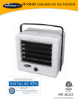
1
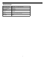
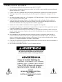
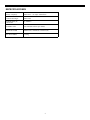
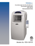
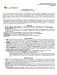
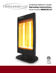
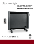
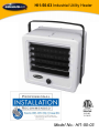
HI1-50-03 Industrial Utility Heater
3092402
V130925
Model No.: HI1-50-03
Thank you for choosing a Soleus Air Utility Heater. This owner’s manual will provide you
with valuable information necessary for the proper care and maintenance of your new product.
Please take a few moments to thoroughly read the instructions and familiarize yourself with all
the operational aspects of your new heater.
For your own records, please attach a copy of your sales receipt to this manual. Also, write the
store name/location, date purchased, and serial number below:
Store Name: ____________________________________________________
Location: ______________________________________________________
Date Purchased: _________________________________________________
Serial Number (located on back of unit): ______________________________
IMPORTANT INSTRUCTIONS
When using this electric unit, basic safety precautions should always be followed to reduce the risk of fire,
electric shock, and injury to persons, including the following:
1. Read ALL instructions before using this unit.
2. CAUTION: Risk of Electric Shock. DO NOT open or try to repair the heater yourself.
3. This heater may get hot when in use. To avoid burns, DO NOT let bare skin touch hot surfaces. If
provided, use handles when moving this heater.
4. Keep combustible materials, such as furniture, pillows, bedding, paper, clothes, and curtains at
least 3 ft from the front of the heater and keep them away from the sides, top, and rear. DO NOT
place towels or other objects on the heater.
5. Extreme caution is necessary when any heater is used by or near children or the disabled, or when
the heater is left operating and unattended.
6. DO NOT operate any heater with a damaged cord or after the heater malfunctions, has been
dropped or damaged in any manner. Return heater to authorized service facility for examination,
electrical or mechanical adjustment, or repair.
7. This heater is not intended for use in bathrooms, laundry areas and similar indoor locations.
NEVER locate heater where it may fall into a bathtub or other water container. To protect against
electrical hazards, DO NOT immerse in water or other liquids.
8. DO NOT do any field-wiring connection with wet hands.
9. DO NOT run cord under carpeting. DO NOT cover cord with throw rugs, runners, or similar coverings. Arrange cord away from traffic area and where it will not be tripped over.
10. DO NOT insert or allow foreign objects to enter any ventilation or exhaust opening as this may
cause an electric shock or fire, or damage the heater.
11. To prevent a possible fire, DO NOT block the air intakes or exhaust in any manner. DO NOT use
2
on soft surfaces, like a bed, where openings may become blocked.
12. A heater has hot and arcing or sparking parts inside. DO NOT use in areas where gasoline, paint,
explosive and/or flammable liquids are used or stored. Keep unit away from heated surfaces and
open flames.
13. Avoid the use of an extension cord because the extension cord may overheat and cause a risk of
fire.
14. To avoid fire or shock hazard, connect the unit directly to a 240V AC power source.
15. Use only for intended use as described in this manual. Any other use not recommended by the
manufacturer may cause fire, electric shock, or injury to persons. The use of attachments not recommended or sold by unauthorized dealers may cause hazards.
16. WARNING: To reduce the risk of fire or electric shock, DO NOT use this unit with any solid-state
speed control device.
17. DO NOT attempt to repair or adjust any electrical or mechanical functions on this unit. Doing so
will void your warranty. The inside of the unit contains no user serviceable parts. Qualified personnel should perform all servicing only.
18. Connect to properly grounded power source only.
19. SAVE THESE INSTRUCTIONS.
3
SAFETY INFORMATION
1.
2.
3.
4.
5.
Use Copper wire only rated at least 60°C (140°F)
For supply connections use No.10 AWG or larger wires suitable for at least 60°C (140°F)
Heater air flow must be directed parallel to, or away from, adjacent walls.
Observe wall, floor, and ceiling clearance requirements on DIAGRAM 1 on Page 6 of this manual.
Do not install closer than 1 5/8” (41.27mm) from the ceiling, 7.9 feet (2.4 meters) from the floor,
or 13” (330mm) from a wall.
6. All wiring must conform to national and local electrical codes in the United States and the heater
must be grounded as a precaution against possible electrical shock. Heater circuit must be
protected with proper fuses.
7. Install only in an area where the proper power-supply connections are available.
8. The mounting structure and the anchoring hardware must be capable of easily and reliably
support the weight of the heater and the mounting bracket (if used).
9. All electrical power must be disconnected and the main service box must be locked before
installing, inspection, cleaning, or servicing the heater to prevent the chance of electrical shock.
10. This heater is not suitable for use in hazardous locations as defined by the National Fire Protection
Association (NFPA) in the United States. This heater has hot and arcing (sparking) parts inside.
Do not use in areas where gasoline, paint, or flammable liquids are used or stored.
11. This heater is not suitable for use in corrosive atmospheres such as marine, greenhouses, or
chemical storage areas.
12. Do not install less than 7.9 feet (2.4 meters) from of the floor.
Improper installation or failure to follow the
instructions outlined in this product manual
can result in electrical shock.
CAUTION
RISK OF ELECTRIC SHOCK
DO NOT OPEN
NO USER-SERVICEABLE PARTS INSIDE
4
SPECIFICATIONS
Voltage Rating / Amps
208V-240 V / 21 Amps / Single Phase
Power Consumption
5000 Watts
Heating BTU’s
17,100 BTU
Air Flow
270 CFM
Unit Size
15.75" W x 11.25" D x 14.375" H
Unit Weight
27 lbs.
5
HEATER LOCATION AND INSTALLATION
Install the heater out of traffic areas maintaining the required clearances below. The direction of air flow shold
not be restricted by anything and the air flow should not blow directly at exposed walls. When more than one
heater is used in an area, the heaters should be arranged so that the air discharge of each heater supports the air
flow of the other heater(s) to provide optimal circulation of warm air
DIAGRAM 1
MINIMUM
DISTANCE
TO WALL
13”
15.7”
11.29”
5 1/2”
24”
MINIMUM
DISTANCE
FROM
DISCHARGE TO
ANY OBJECT
MOUNTING
LOCATION
14.37”
Note: Min. clearance to ceiling when
not using mounting brackets is 1 5/8”
MINIMUM
DISTANCE TO
FLOOR 7.9 ft.
MAXIMUM MOUNTING HEIGHT FOR:
Vertical air delivery unit = 11 ft.
Horizontal air delivery unit = 8 ft.
FRONT VIEW
SIDE VIEW
6
LOCATION AND INSTALLATION (CONT.)
MOUNTING THE BRACKET
1. Locate a stud in the ceiling joist.
2. Remove the mounting bracket from the heating unit be loosening the bracket screws with a
wrench and slipping the handle off over the screw heads.
3. Place a washer on the screws before inserting through the holes in the mounting bracket and
screw them securely into the ceiling joist. NOTE: If you want the heater to swivel side to side,
add a washer to both sides of the bracket. A longer lag bolt may be required to properly secure
the unit.
4. Tighten the screw enough to securely hold the heater with the airflow pointed in the proper direction.
SINGLE –SCREW MOUNTING
DOUBLE –SCREW MOUNTING
HANGING THE HEATER
1. Lift the heater up and into the mounting bracket.
2. Align the bracket screws with the keyhole slots in the mounting brackets.
3. If the heater is to be tilted, it must be positioned in the keyhole slots.
4. Tighten the bracket screws with a wrench so the unit is securely suspended at the desired horizontal or vertical level.
7
LOCATION AND INSTALLATION (CONT.)
CONNECTING THE POWER (HARDWIRING)
1. Turn off the power at the main service.
2. Remove the screw from the back of the unit to connect the power to the heater.
3. Attach the cable connectors to the unit and slide the 10 gauge wire through the cable connector.
NOTE: For certain applications, conduit may be required. Check your local electrical codes. If
you run the wiring in conduit and wish to be able to rotate the heater, be sure to purchase
enough flexible conduit to allow the heater to be rotated.
4. Connect the wire to the power terminal block located in the base of the heater.
5. Turn on the power at the main service.
208V-240V
8
LOCATION AND INSTALLATION (CONT.)
CONNECTING THE HEATER TO A 208V-240V / 30AMP PLUG (SOLD SEPARATELY)
1. Remove the screws from the back of the unit to remove the cover.
2. Attach the 208V-240V / 30 AMP Plug to the heater using the Live: L1 and L2,
(Also called “Line” or “Hot”), and Ground wires from the plug.
3. Connect the wires to the corresponding connections on the power terminal block located in the
base of the heater.
4. Connect the plug to a 208V-240V / 30Amp outlet.
9
OPERATION
NOTE: The first time you operate this heater, it may emit a slight odor and some smoke. This is due
to the residual cleaning agents used to clean the element during manufacturing. This is normal operation and will cease after the heater has been used for a few minutes.
ADJUSTING THE AIR FLOW DIRECTION
1. Rotating the unit - if the unit has been installed with a single lag bolt, simply rotate the entire unit
as needed to adjust the direction of the air flow.
2. Tilting the unit - Loosen the bracket screws, tilt the heater to the desired position, and re-tighten
the bracket screws. NOTE: To tilt the heater it must be mounted in bottom keyhole slots of
mounting brackets to maintain adequate clearance and prevent possible overheating.
3. Adjust the louvers to the desired position. NOTE: The louvers are designed so they cannot be
completely closed. Do not attempt to close the louvers completely as this may damage the unit.
.
To prevent possible electric shock, disconnect the power to the heater at the main service box before attempting to adjust the heat output of the unit.
10
MAINTENANCE
To prevent possible electric shock, disconnect the power to the heater at the main service box before attempting inspect or clean the unit.
Use care to prevent damage to the internal components of the heater when cleaning the heating element. Make
sure all connections remain tight and all wiring is routed away from the element fins when reassembling the
unit. Allowing wiring to touch the element fins could result in a fire hazard.
CLEANING THE FAN AND MOTOR
Remove the protective grille from the rear of the heater. This provides access to the fan and motor. Wipe off
the fan and motor with a soft cloth or brush. The fan motor does not require lubrication. Replace the protective
grille when finished.
WIRING DIAGRAM
11
WARRANTY
One Year Limited Warranty
Soleus Home Comfort warrants the accompanying Soleus Air Heater to be free of defects in material and workmanship for the applications specified in its operation instruction for a period of ONE (1) year from the date of original retail purchase in the United States.
If the unit exhibits a defect in normal use, Soleus Home Comfort will, at its option, either repair or replace it, free of
charge within a reasonable time after the unit is returned during the warranty period.
As a condition to any warranty service obligation, the consumer must present this Warranty Certificate along with a
copy of the original purchase invoice.
THIS WARRANTY DOES NOT COVER:
• Damage, accidental or otherwise, to the unit while in the possession of a consumer not caused by a defect in
material or workmanship.
• Damage caused by consumer misuse, tampering, or failure to follow the care and special handling provisions
in the instructions. This includes dents, accidental or otherwise, to the base and head of the unit.
• Damage to the finish of the case, or other appearance parts caused by wear.
• Damage caused by repairs or alterations of the unit by anyone other than those authorized by Soleus Home
Comfort.
• Freight and Insurance cost for the warranty service.
ALL WARRANTIES, INCLUDING ANY IMPLIED WARRANTY OF MERCHANT ABILITY ARE LIMITED TO
ONE-YEAR DURATION OF THIS EXPRESS LIMITED WARRANTY. SOLEUS HOME COMFORT
DISCLAIMS ANY LIABILITY FOR CONSEQUENTIAL OR INCIDENTAL DAMAGES AND IN NO EVENT
SHALL SOLEUS HOME COMFORT’S LIABILITY EXCEED THE RETAIL VALUE OF THE UNIT FOR
BREACH OF ANY WRITTEN OR IMPLIED WARRANTY WITH RESPECT TO THIS UNIT.
This warranty covers only new products purchased from our authorized dealers or retailers. It does not cover used, salvaged, or refurbished products.
As some states do not allow the limitation or exclusion of incidental or consequential damages, or do not allow
limitation on implied warranties, the above limitations and exclusions may not apply to you. This warranty gives you
specific legal rights, and you may also have other rights that vary from state to state.
For Technical Support or Warranty Service
Please Call (888) 876-5387
Or Write To:
Soleus Home Comfort
17911 East Ajax Circle
City of Industry, CA 91748 USA
www.soleushomecomfort.com
12
HI1-50-03 Calentador de Uso Industrial
3092402
V130925
Modelo Nro.: HI1-50-03
Gracias por elegir el Calentador de Uso Industrial de Soleus Air. Este manual del propietario le proveerá
valiosa información necesaria para el cuidado y mantenimiento apropiado de su nuevo producto. Por favor
tome unos momentos para leer detenidamente las instrucciones y familiarizarse con todos los aspectos
operacionales de su nuevo calentador de Soleus Air.
Mantenga una copia del recibo de venta con este manual para su información. También, escriba a continuación
el nombre de la tienda/dirección, fecha de compra, y número de serie:
Nombre de Tienda: _________________________________________________________________
Dirección de Tienda: ________________________________________________________________
Fecha de Compra: __________________________________________________________________
Número de Serie (ubicado en la parte de atrás de la unidad): ______________________________
INSTRUCCIONES IMPORTANTES
Cuando utilice esta unidad eléctrica, precauciones básicas de seguridad se deben seguir siempre para así reducir
el riesgo de incendio, descarga eléctrica, y daños a personas, incluyendo las siguientes instrucciones:
1. Lee TODAS las instrucciones antes de utilizar este calentador
2. CUIDADO: Riesgo de Descarga Eléctrica. NO abra o trate usted de reparar el calentador.
3. Este calentador se podría calentar cuando esta en uso. Para evitar quemaduras, NO tocar con la piel las
superficies calientes. Si se proveen, utilice las manijas cuando mueva el calentador.
4. Mantenga materiales combustibles tales como muebles, almohadas, ropa de cama, papel, ropa, y
cortinas a una distancia de por lo menos 3 pies de el frente del calentador y manténgalos alejados de
los lados así como de la parte de atrás. NO coloque toallas o algún otro objeto sobre el calentador.
5. Cuidado extremo es necesario cuando cualquier calentador es usado por o cerca de niños, personas
incapacitadas, o cuando el calentador se deje operando y desatendido.
6. NO opere ningún calentador con un cable dañado o después de algún malfuncionamiento del
calentador, o si el calentador fue tirado, golpeado, o si fue dañado de alguna manera. Devuelva el
calentador a un agente autorizado de servicio para revisión, ajuste eléctrico, mecánico o reparación.
7. Este calentador no es para uso en baños, áreas de lavandería, o áreas cerradas similares. NUNCA
ubique el calentador donde podría caer dentro de la tina de agua o algún otro contenedor de agua. Para
protegerse contra riesgo de descarga eléctrica, NO lo sumerja en el agua o cualquier otro liquido.
8. No proceda a conectar cables con las manos mojadas.
9. NO coloque el cable debajo de la alfombra, NO cubra el cable con alfombras de centro, pasillos, o
similares. Coloque el cable lejos de las áreas de trafico y donde no exista riesgo de tropiezo.
10. NO introduzca o permita que objetos extraños entren en cualquier vía de ventilación o escape ya que
esto podría causar una descarga eléctrica o incendio, así como daños al calentador.
11. Para prevenir un posible incendio, NO bloquee las vías de entrada o salida de aire. NO use el
calentador en superficies blandas, como la cama, ya que las entradas o salidas del aire podrían ser
bloqueadas.
2
12. Un calentador tiene en su interior partes calientes, ardientes, o chispeantes. NO usar en áreas donde
gasolina, pintura, explosivos, y/o líquidos inflamables son usados o almacenados. Mantenga la unidad lejos
de las superficies calientes o llamas de fuego expuestas.
13. Evite usar extensiones eléctricas ya que la extensión eléctrica podría sobrecalentarse y causar el riesgo de
un incendio.
14. Para prevenir un peligro de choque electrico, conecte la unidad directamente a una fuente electrica de 240V.
15. El uso de esta unidad debe ser como se indica en este manual. Cualquier otro uso que no este
recomendado por el fabricante podría causar un incendio, descarga eléctrica, o heridas a personas. El uso
de cualquier artefacto extra no recomendado o vendido por distribuidores no autorizados podrían causar
daños o ser peligrosos.
16. ADVERTENCIA: Para reducir el riesgo de incendio o descarga eléctrica, NO utilice esta unidad con
ningún dispositivo de control de velocidad.
17. NO intente reparar o ajustar ninguna función eléctrica o mecánica de esta unidad. Si usted lo hace, anulara
la garantía. La parte interna de la unidad contiene partes no útiles para el usuario. Solo personal calificado
debe dar servicio a la unidad.
18. Instale unicamente a una fuente de alimentacion apropiadamente conectada a tierra.
19. GUARDE ESTAS INSTRUCCIONES.
3
INFORMACION DE SEGURIDAD
1. Use únicamente alambre de cobre para no menos de 60°C (140°F).
2. Para conexiones de suministro eléctrico use cables No.10 AWG o mayor medida, que sean adecuados
para no menos de 60°C (140°F).
3. El flujo de aire de el calentador debe estar dirigido paralelamente o alejado de las paredes adyacentes.
4. Mantenga el espacio libre entre paredes, piso, y techo requerido en diagrama 1 en pagina 6 de este
manual.
5. No instalar la unidad a menos de 1 y 5/8 pulgadas (41.27mm) del techo, a 7.9 pies (2.4 metros) del piso,
o a 13 pulgadas (330mm) de la pared.
6. Todos los cables deben estar conforme a los códigos eléctricos de los Estados Unidos, además el
calentador debe tener conexión tierra como precaución en caso de posibles descargas eléctricas. El
circuito del calentador debe estar protegido con los fusibles apropiados.
7. Instalar solo en áreas donde el suministro eléctrico apropiado este disponible.
8. La estructura de montaje y los accesorios de soporte deben ser capaces de fácil y seguramente soportar
el peso del calentador y las escuadras de montaje (si se usan).
9. Todo el suministro eléctrico debe ser desconectado y la caja principal de fusibles se debe desconectar
antes de instalar, inspeccionar, limpiar o dar servicio al calentador para de esta forma prevenir el riesgo
de descarga eléctrica.
10. Este calentador no esta adecuado para usarlo en lugares riesgosos o peligrosos como lo define la
Asociación Nacional de Protección contra el Fuego (NFPA) en los Estados Unidos. Un calentador
tiene en su interior partes calientes, ardientes, o chispeantes. No usar en áreas donde gasolina, pintura,
explosivos, y/o líquidos inflamables son usados o almacenados.
11. El uso de este calentador no esta adecuado para atmosferas corrosivas como la marina, invernaderos, o
áreas donde se almacenen químicos.
12. No se instale esta unidad a menos de 7.9 pies (2.4 metros) del piso.
La instalación inapropiada o el incumplimiento de
las instrucciones incluidas en este manual del
producto puede resultar en descarga eléctrica.
CUIDADO
RIESGO DE DESCARGA ELECTRICA.
NO LO ABRA
PARTES NO UTILES PARA EL USARIO
ADENTRO.
4
ESPECIFICACIONES
Voltaje / Amperaje
208V-240 V / 21 Amps / Monofásico
Consumo de Energía
5000 Vatios
Unidades (BTU) de
Calefacción
17,100 BTU
Ventilador CFM
270 CFM (Pies cúbicos por minuto)
Tamaño de Unidad
400mm (An) x 286mm (P) x 365mm (Al)
Peso de la Unidad
12.2 Kg
5
UBICACION E INSTALACION DEL CALENTADOR
Instale el calentador fuera de áreas de trafico manteniendo el espacio libre requerido en las especificaciones.
La dirección del flujo de aire no debe ser restringido por nada y el flujo de aire no debe soplar directamente a
paredes expuestas. Cuando mas de un calentador es usado en un área especifica, los calentadores se deben
ubicar de manera que la descarga de aire de cada calentador apoye el flujo de aire del otro (s) para así proveer
una optima y mejor circulación del aire.
DIAGRAMA 1
Distancia
mínima a la
Pared es
13” pulg.
15.7”
11.29”
5 1/2”
24”
14.37”
Nota: Distancia mínima al techo es
de 1 5/8” (Pulg) , cuando no se usan
los soportes de montaje
Distancia mínima
de la descarga
Hacia cualquier
Objeto.
Ubicación
de Montaje
Distancia mínima
al piso es de 7.9
pies.
Altura máxima de montaje para:
Unidad de aire vertical= 11 pies
Unidad de aire horizontal= 8 pies
VISTA FRONTAL
VISTA LATERAL
6
UBICACION E INSTALACION (CONT.)
MONTAJE DEL SOPORTE
1. Localice un poste/viga en el techo.
2. Quite el soporte de montaje de la unidad de calefacción aflojando los tornillos con una llave y
deslizando la manija sobre las cabezas de los tornillos.
3. Coloque una arandela en el tornillo antes de insertarlo a través de los hoyos guía en el soporte
de montaje y atorníllelos firmemente a la poste/viga del techo. NOTA: Si usted desea que el
calentador gire de lado a lado, agregue una arandela a ambos lados del soporte. Un perno/
tornillo mas largo se podría necesitar para asegurar apropiadamente la unidad.
4. Apreté los tornillos suficientemente para sujetar con seguridad el calentador con el flujo de aire
en la dirección apropiada.
Poste/Viga techo
Poste/Viga techo
Arandela
Arandela
Soporte
Soporte
Perno/
Tornillo Diagonal
Perno/
Tornillo Diagonal
MONTAJE DE UN-TORNILLO
MONTAJE DE TORNILLO-DOBLE
COLGANDO EL CALENTADOR
1. Levante y coloque el calentador en el soporte de montaje.
2. Los tornillos del soporte se deben alinear con los hoyos-guía de los soportes.
3. Si el calentador se tiene que inclinar, debe ser colocado en los hoyos-guía.
4. Apriete los tornillos con una llave para que la unidad este suspendida con seguridad al nivel
horizontal/vertical deseado.
7
UBICACION E INSTALACION (CONT.)
CONECTANDO EL SUMINISTRO DE ENERGIA:
1. Apague el suministro de energía de la caja central de circuitos.
2. Quite los tornillos de la parte trasera de la unidad para conectar la energía al calentador.
3. Sujete los conectores de cable a la unidad y deslice el cable #10 a través de conector de cable.
Nota: Para ciertas aplicaciones, tubo de conducto podría ser requerido. Revise los códigos
locales de electricidad. Si usted usa tubo de conducto para instalar los cables y desea poder
girar el calentador, asegúrese de comprar suficiente tubo de conducto flexible para permitir que
la unidad pueda rotar.
4. Conecte los cables al bloque terminal de energía localizado en la base del calentador.
5. Encienda el suministro de energía en la caja central de circuitos.
208V-240V
8
UBICACION E INSTALACION (CONT.)
Conectando el calentador a un enchufe de 208V-240V 30 Amp ( adquisición adicional)
1. Sacar los tornillos de la parte trasera de la unidad para retirar la cubierta
2. Conecte el enchufe de 208V-240V /30 AMP al calentador usando los cables L1, L2
y G (tierra) del enchufe de la unidad
3. Conectar los alambres a los terminales correspondientes ubicados en el bloque de
terminales eléctricos en la base del calentador
4. Conectar el enchufe en un tomacorriente de 208V-240V / 30 Amp
9
OPERACION/USO
NOTA: La primera vez que usted usa/opera este calentador, podría emitir un ligero olor y
algo de humo. Esto se debe al residuo de agentes de limpieza utilizados para limpiar las
partes durante su manufactura. Esto es normal y cesara cuando el calentador sea usado por
unos pocos minutos.
AJUSTANDO LA DIRECCION DEL FLUJO DE AIRE
1. Rotando la unidad– Si la unidad ha sido instalada usando solamente un perno/tornillo,
simplemente gire/rote la unidad entera hacia el lugar deseado para ajustar la dirección del flujo
de aire.
2. Inclinando la unidad– Afloje los tornillos de soporte, incline el calentador a la posición deseada y
apriete los tornillos del soporte. NOTA: Para inclinar el calentador debe estar montado en los
hoyos-guía inferiores de los soportes de montaje para mantener el espacio libre adecuado y
prevenir posible sobre-calentamiento.
3. Ajuste las rejillas a la posición deseada. NOTA: Las rejillas están diseñadas para que no se
puedan cerrar completamente. No trate de cerrar las rejillas completamente ya que podrían
dañar la unidad.
Para prevenir posible descarga eléctrica, desconecte el suministro de energía al calentador de la
caja principal de suministro eléctrico antes de tratar de ajustar la salida de la calefacción de la
unidad.
10
MANTENIMIENTO
Para prevenir posibles descargas eléctricas, desconecte el suministro eléctrico de la caja principal
de circuitos antes de intentar inspeccionar o limpiar la unidad.
Tenga cuidado cuando limpie el elemento de calefacción para prevenir daños a componentes internos del
calentador. Asegúrese que todas las conexiones permanezcan ajustadas y que todo el cableado este fuera del
alcance de las aletas cuando este re-ensamblando la unidad. Si los alambres tocan las aletas podría resultar en
riesgo de incendio.
LIMPIANDO EL VENTILADOR Y EL MOTOR:
Quite la rejilla protectora de la parte de atrás del calentador. Esto le facilitara el acceso al ventilador y al
motor. Limpie el ventilador y el motor con una toalla suave o escobilla, El motor del ventilador no requiere
lubricación. Coloque la rejilla protectora cuando termine.
Rejilla Protectora
Ventilador y Motor
Diagrama De Cableado Electrico
11
GARANTIA
Un Año de Garantía Limitada
Soleus Home Comfort garantiza que el calentador adjunto esta libre de defectos en materiales y manufactura para las
aplicaciones especificas en sus instrucciones de operación por un periodo de UN (1) año de la fecha de compra original
en los Estados Unidos.
Si la unidad muestra un defecto por uso normal, Soleus Home Comfort podría optar por, ya sea reparar o reemplazar
la unidad libre de cargos, dentro de un tiempo razonable después de que la unidad ha sido regresada durante el periodo
de garantía.
Como condición de cualquier obligación de servicio de garantía, el consumidor debe presentar este Certificado de
Garantía así como una copia de la factura original de compra.
ESTA GARANTIA NO CUBRE:
• Daños accidentales o no a la unidad mientras este en posesión del consumidor que no fueron causados por
defecto en materiales o manufactura.
• Daños causados por el mal uso del consumidor, manipulación, o por no seguir las indicaciones de cuidado y
provisiones de manejo especial en las instrucciones.
• Daños al acabado exterior del calentador, u otras aspectos de apariencia en el acabado causadas por el uso.
• Daños causados por reparaciones o alteraciones a la unidad por cualquier otra persona que no este autorizada
por Soleus Home Comfort.
• Costos de Envió y Seguro para el servicio de garantía..
TODAS LAS GARANTIAS, INCLUYENDO CUALQUIER GARANTIA IMPLICITA EN LA CAPACIDAD DEL
COMERCIANTE ESTA LIMITADA A UN AÑO DE DURACION DE ESTA GARANTIA EXPRESA LIMITADA .
SOLEUS HOME COMFORT HACE DESCARGO DE CUALQUIER RESPONSABLILIDAD POR DAÑOS
INCIDENTALES O CONSECUENTES Y DE NINGUNA FORMA SOLEUS HOME COMFORT TENDRA
RESPONSIBLILIDAD QUE EXCEDA EL VALOR DE VENTA AL DETALLE DE LA UNIDAD POR
INCUMPLIMIENTO DE CUALQUIER GARANTIA YA SEA ESCRITA O IMPLICITA CON RESPECTO A ESTA
UNIDAD.
Esta garantía cubre solamente productos nuevos comprados a distribuidores autorizados o vendedores minorista. No
cubre mercancía usada, salvada, o reconstruida. .
Ya que algunos estados no permiten la limitación o exclusión de daños incidentales o consecuentes, o no permiten
limitación en garantías implícitas, las limitaciones y exclusiones antes mencionadas podrían no aplicar a usted. Esta
garantía le da derechos legales específicos, y usted podría tener otros derechos que varían de estado a estado.
Para Apoyo Técnico y Servicio de Garantía
Por favor llamar (888) 876-5387
O Escriba:
Soleus Home Comfort
17911 East Ajax Circle
City of Industry, CA 91748 USA
www.soleushomecomfort.com
12