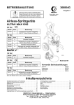
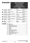
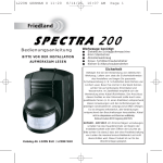
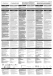
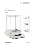
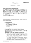
1
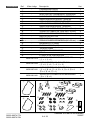
INSTALLATION INSTRUCTIONS
INSTRUCTIONS DE MONTAGE
MONTAGEANLEITUNG
ISTRUZIONI DI MONTAGGIO
INSTRUCCIONES PARA EL MONTAJE
Description:
GB
Applications:
Description:
F
Applications:
D
I
WINDSHIELD ASSEMBLY LONG
WINDSHIELD ASSEMBLY SHORT
VZ1500 / M90
ENSEMBLE DE PARE-BRISE LONG
ENSEMBLE DE PARE-BRISE COURT
VZ1500 / M90
Part Nr:
Installation Time:
99000-99074-77N
99000-99074-78N
1.0 hr(s)
Code:
99000-99074-77N
99000-99074-78N
Temps d’installation: 1,0 hr(s)
Beschreibung: WINDSCHUTZSCHEIBEN-BAUGRUPPE LANG
WINDSCHUTZSCHEIBEN-BAUGRUPPE KURZ
Verwendungen: VZ1500 / M90
Teil-Nr.:
Montagezeit:
Descrizione:
Nºdi codice:
99000-99074-77N
99000-99074-78N
1,0 hr(s)
GRUPPO DEL PARABREZZA LUNGO
GRUPPO DEL PARABREZZA CORTO
Applicazione: VZ1500 / M90
99000-99074-77N
99000-99074-78N
Tempo di montaggio: 1,0 hr(s)
Descripción:
Nºde código:
E
Aplicación:
99000-99074-77N
99000-99074-78N
CONJUNTO DEL PARABRISAS LARGO
CONJUNTO DEL PARABRISAS CORTO
VZ1500 / M90
1 of 29
99000-99074-77N
99000-99074-78N
Tiempo de instalación: 1,0 hr(s)
GENUINE SUZUKI ACCESSORIES
200807
CONTENTS
P.No
①
②
③
④
⑤
⑥
⑦
⑧
⑨
⑩
⑪
⑫
⑬
⑭
⑮
⑯
⑰
⑱
⑲
⑳
99000-99074-77N
99000-99074-78N
Part No.
Description
WINDSHIELD LONG
WINDSHIELD SHORT
WINDSHIELD MOUNT, LEFT
WINDSHIELD MOUNT, RIGHT
CLAMP UPPER, F
CLAMP UPPER, R
CLAMP LOWER, F
CLAMP LOWER, R
CAP HEAD BOLT (M6 × 18mm)
CAP HEAD BOLT (M6 × 25mm)
BUTTON HEAD BOLT (M8 × 18mm)
GROMMET
SPACER
BUTTON HEAD BOLT (M6 × 20mm)
WASHER (6 × 24mm)
CAP NUT (M6)
RUBBER CAP
METER COVER
SEAL
CAUTION LABEL
99000-99074-A19 WINDSHIELD MOUNT R/L ( ③ × 1, ④ × 1)
CLAMP SET, WINDSHIELD
99000-99074-A20
( ⑤ × 2, ⑥ × 2, ⑦ × 2, ⑧ × 2)
Q.ty
1
1
1
1
2
2
2
2
4
4
4
4
4
4
4
4
1
1
1
1
1
1
99000-99074-A21
BOLT SET, WINDSHIELD
( ⑨ × 4, ⑩ × 4, ⑪ × 4, ⑫ × 4, ⑬ × 4, ⑭ × 4,
⑮ × 4, ⑯ × 4, ⑰ × 1)
1
99000-99013-K61
METER COVER SET ( ⑱ × 1, ⑲ × 1)
1
2 of 29
GENUINE SUZUKI ACCESSORIES
200807
CONTENU
Réf.
①
②
③
④
⑤
⑥
⑦
⑧
⑨
⑩
⑪
⑫
⑬
⑭
⑮
⑯
⑰
⑱
⑲
⑳
99000-99074-77N
99000-99074-78N
Code
-
Description
PARE-BRISE LONG
PARE-BRISE COURT
SUPPORT DE PARE-BRISE, GAUCHE
SUPPORT DE PARE-BRISE, DROIT
COLLIER SUPÉRIEUR, AV
COLLIER SUPÉRIEUR, AR
COLLIER INFÉRIEUR, AV
COLLIER INFÉRIEUR, AR
BOULON SIX PANS CREUX (M6 × 18mm)
BOULON SIX PANS CREUX (M6 × 25mm)
BOULON À TÊTE RONDE (M8 × 18mm)
PASSE-CABLE
ENTRETOISE
BOULON À TÊTE RONDE (M6 × 20mm)
RONDELLE (6 × 24mm)
ECROU BORGNE (M6)
CACHE EN CAOUTCHOUC
COUVERCLE DU COMPTEUR
JOINT
ÉTIQUETTE D’AVERTISSEMENT
MONTURE DE PARE-BRISE G/D
99000-99074-A19
( ③ × 1, ④ × 1)
Q.té
1
1
1
1
2
2
2
2
4
4
4
4
4
4
4
4
1
1
1
1
1
99000-99074-A20
ENSEMBLE DE COLLIERS, PARE-BRISE
( ⑤ × 2, ⑥ × 2, ⑦ × 2, ⑧ × 2)
1
99000-99074-A21
ENSEMBLE DE BOULONS, PARE-BRISE
( ⑨ × 4, ⑩ × 4, ⑪ × 4, ⑫ × 4, ⑬ × 4, ⑭ × 4,
⑮ × 4, ⑯ × 4, ⑰ × 1)
1
99000-99013-K61
COUVERCLE D’INSTRUMENTATION
( ⑱ × 1, ⑲ × 1)
1
3 of 29
GENUINE SUZUKI ACCESSORIES
200807
INHALT
99000-99074-77N
99000-99074-78N
Nr.
①
②
③
④
⑤
⑥
⑦
⑧
⑨
⑩
⑪
⑫
⑬
⑭
⑮
⑯
⑰
⑱
⑲
⑳
Teil-Nr
-
Beschreibung
WINDSCHUTZSCHEIBE LANG
WINDSCHUTZSCHEIBE KURZ
WINDSCHUTZSCHEIBENBEFESTIGUNG, LINKS
WINDSCHUTZSCHEIBENBEFESTIGUNG, RECHTS
OBERE KLAMMER VORNE
OBERE KLAMMER HINTEN
UNTERE KLAMMER VORNE
UNTERE KLAMMER HINTEN
INBUSSCHRAUBE (M6 × 18mm)
INBUSSCHRAUBE (M6 × 25mm)
HALBRUNDSCHRAUBE (M8 × 18mm)
DURCHFÜHRDICHTUNG
DISTANZSTÜCK
HALBRUNDSCHRAUBE (M6 × 20mm)
UNTERLEGSCHEIBE (6 × 24mm)
HUTMUTTER (M6)
GUMMIKAPPE
INSTRUMENTENVERKLEIDUNG
DICHTUNG
VORSICHTSSCHILD
WINDSCHUTZSCHEIBENBEFESTIGUNG
99000-99074-A19
R/L ( ③ × 1, ④ × 1)
Stck
1
1
1
1
2
2
2
2
4
4
4
4
4
4
4
4
1
1
1
1
1
99000-99074-A20
KLAMMERSATZ, WINDSCHUTZSCHEIBE
( ⑤ × 2, ⑥ × 2, ⑦ × 2, ⑧ × 2)
1
99000-99074-A21
SCHRAUBENSATZ, WINDSCHUTZSCHEIBE
( ⑨ × 4, ⑩ × 4, ⑪ × 4, ⑫ × 4, ⑬ × 4, ⑭ × 4,
⑮ × 4, ⑯ × 4, ⑰ × 1)
1
99000-99013-K61
INSTRUMENTENBLENDE ( ⑱ × 1, ⑲ × 1)
1
4 of 29
GENUINE SUZUKI ACCESSORIES
200807
IMBALLO
99000-99074-77N
99000-99074-78N
Rif.
①
②
③
④
⑤
⑥
⑦
⑧
⑨
⑩
⑪
⑫
⑬
⑭
⑮
⑯
⑰
⑱
⑲
⑳
Nºdi codice
-
Descrizione
PARABREZZA LUNGO
PARABREZZA CORTO
ATTACCO DEL PARABREZZA, SINISTRO
ATTACCO DEL PARABREZZA, DESTRO
ARRESTO SUPERIORE, A
ARRESTO SUPERIORE, P
ARRESTO INFERIORE, A
ARRESTO INFERIORE, P
BULLONE A CAPPELLO (M6 × 18 mm)
BULLONE A CAPPELLO (M6 × 25 mm)
BULLONE A TESTA TONDA (M8 × 18mm)
ANELLO IN GOMMA
DISTANZIATORE
BULLONE A TESTA TONDA (M6 × 20mm)
RONDELLA (6 × 24mm)
DADO A CAPPELLO (M6)
TAPPO IN GOMMA
COPERTURA DELLA STRUMENTAZIONE
ADESIVO
ETICHETTA DI AVVERTENZA
INNESTO DEL PARABREZZA D/S
99000-99074-A19
( ③ × 1, ④ × 1)
Q.tà
1
1
1
1
2
2
2
2
4
4
4
4
4
4
4
4
1
1
1
1
1
99000-99074-A20
CORREDO ARRESTI, PARABREZZA
( ⑤ × 2, ⑥ × 2, ⑦ × 2, ⑧ × 2)
1
99000-99074-A21
CORREDO BULLONI, PARABREZZA
( ⑨ × 4, ⑩ × 4, ⑪ × 4, ⑫ × 4, ⑬ × 4, ⑭ × 4,
⑮ × 4, ⑯ × 4, ⑰ × 1)
1
99000-99013-K61
CORREDO VISIERA STRUMENTAZIONE
( ⑱ × 1, ⑲ × 1)
1
5 of 29
GENUINE SUZUKI ACCESSORIES
200807
CONTENIDO
Ref.
①
②
③
④
⑤
⑥
⑦
⑧
⑨
⑩
⑪
⑫
⑬
⑭
⑮
⑯
⑰
⑱
⑲
⑳
Nºde código
-
Descripción
PARABRISAS LARGO
PARABRISAS CORTO
MONTURA DEL PARABRISAS, IZQUIERDA
MONTURA DEL PARABRISAS, DERECHA
ABRAZADERA SUPERIOR, FRONTAL
ABRAZADERA SUPERIOR, TRASERA
ABRAZADERA INFERIOR, FRONTAL
ABRAZADERA INFERIOR, TRASERA
PERNO DE CABEZA DE TAPA (M6 × 18 mm)
PERNO DE CABEZA DE TAPA (M6 × 25 mm)
PERNO DE CABEZA REDONDEADA (M8 × 18 mm)
ANILLO PROTECTOR
SEPARADOR
PERNO DE CABEZA REDONDEADA (M6 × 20 mm)
ARANDELA (6 × 24mm)
TUERCA DE TAPA (M6)
TAPA DE GOMA
CUBIERTA DE MEDIDORES
SELLO
ETIQUETA DE PRECAUCIÓN
MONTURA DEL PARABRISAS DER./IZQ.
99000-99074-A19
( ③ × 1, ④ × 1)
Cant.
1
1
1
1
2
2
2
2
4
4
4
4
4
4
4
4
1
1
1
1
1
99000-99074-A20
JUEGO DE PERNOS, PARABRISAS
( ⑤ × 2, ⑥ × 2, ⑦ × 2, ⑧ × 2)
1
99000-99074-A21
JUEGO DE PERNOS, PARABRISAS
( ⑨ × 4, ⑩ × 4, ⑪ × 4, ⑫ × 4, ⑬ × 4, ⑭ × 4,
⑮ × 4, ⑯ × 4, ⑰ × 1)
1
99000-99013-K61
JUEGO DE LA CUBIERTA DE MEDIDORES
( ⑱ × 1, ⑲ × 1)
1
①
⑥
③
⑤
⑦
④
⑧
⑩
⑨
②
⑪
⑫
⑭
⑲
⑮
99000-99074-77N
99000-99074-78N
⑬
⑯
6 of 29
⑰
⑱
⑳
GENUINE SUZUKI ACCESSORIES
200807
TOOLS
REQUIRED
P.No
1.
2.
3.
4.
5.
6.
7.
8.
Description
4mm Hex Bit Socket
5mm Hex Bit Socket
10mm Wrench
Scale
Ratchet
Torque Wrench
Neutral detergent
Shop towel
OUTILS
NÉCESSAIRES
Réf.
1.
2.
3.
4.
5.
6.
7.
8.
Description
Douille hexagonale 4mm
Douille hexagonale 5mm
Clé 10mm
Règle graduée
Clé à cliquet
Clé dynamométrique
Détergent neutre
Chiffon d’atelier
NOTWENDIGE
WERKZEUGE
Nr.
1.
2.
3.
4.
5.
6.
7.
8.
Beschreibung
4mm Sechskant-Stecknuss
5mm Sechskant-Stecknuss
10mm Schraubenschlüssel
Messlineal
Ratsche
Drehmomentschlüssel
Neutrales Reinigungsmittel
Lappen
ATTREZZATURA
RICHIESTA
Rif.
1.
2.
3.
4.
5.
6.
7.
8.
Descrizione
Chiave a bussola esagonale da 4mm
Chiave a bussola esagonale da 5mm
Chiave da 10mm
Righello
Chiave a cricchetto
Chiave torsiometrica
Detergente neutro
Straccio da officina
99000-99074-77N
99000-99074-78N
7 of 29
GENUINE SUZUKI ACCESSORIES
200807
HERRAMIENTAS
NECESARIAS
Ref.
1.
2.
3.
4.
5.
6.
7.
8.
1.2.
IMPORTANT
Descripción
Cabezal de broca hexagonal de 4mm
Cabezal de broca hexagonal de 5mm
Llave de 10mm
Regla
Trinquete
Llave dinamométrica
Detergente neutro
Paño de taller
3.
5.
4.
6.
7.
8.
Please read this manual and follow its instructions carefully. To emphasize
special information, the symbol and the words WARNING, CAUTION and
NOTE have special meanings. Pay special attention to the messages highlighted
by these signal words.
WARNING
Indicates a potential hazard that could result in death or injury.
CAUTION
Indicates a potential hazard that could result in vehicle damage.
NOTE: indicates special information to make maintenance easier or instructions
clearer.
IMPORTANT
Veuillez lire ce manuel et respecter strictement les instructions y comprises.
Afin de souligner des informations particulières, le symbole et les termes
AVERTISSEMENT, ATTENTION et REMARQUE ont des significations
particulières. Accordez une attention particulière aux informations mises en
relief à l’aide de ces mots signaux.
AVERTISSEMENT
Ce mot appelle l’attention sur un danger possible pouvant se traduire par une
blessure, voire la mort.
ATTENTION
Attire votre attention sur un risque potentiel susceptible d’entraîner un
endommagement du véhicule.
REMARQUE: attire votre attention sur des informations spéciales qui servent à
faciliter l’entretien ou à clarifier les instructions.
99000-99074-77N
99000-99074-78N
8 of 29
GENUINE SUZUKI ACCESSORIES
200807
WICHTIG
Bitte lesen Sie diese Anleitung und befolgen Sie ihre Anweisungen sorgfältig.
Um besondere Informationen hervorzuheben, haben das Symbol sowie die
Wörter WARNUNG, VORSICHT und HINWEIS besondere Bedeutungen. Achten
Sie besonders auf die Textstellen, die durch diese Signalwörter hervorgehoben
sind.
WARNUNG
Macht auf eine potenzielle Gefahr aufmerksam, die den Tod oder eine
Verletzung zur Folge haben kann.
VORSICHT
Weist auf eine mögliche Gefahr hin, die zu Schäden am Fahrzeug führen
könnte.
HINWEIS: weist auf spezielle Informationen hin, um die Wartung sicherer oder
die Anleitung verständlicher zu machen.
IMPORTANTE Si consiglia di leggere e seguire le presente istruzioni molto attentamente. Per
dare particolare rilievo a determinate informazioni, vengono impiegati il simbolo
e le parole ATTENZIONE e PRECAUZIONE e NOTA hanno significati
particolari.Si prega di prestare molta attenzione alle parti del testo dove sono
contenute queste parole.
ATTENZIONE
Indica un pericolo potenziale che potrebbe risultare in decessi o infortuni.
PRECAUZIONE
Indica un possibile danno che può causare danni alla vettura.
NOTA: indica un’informazione particolare per rendere la manutenzione più
facile o leinformazioni più chiare.
IMPORTANTE Por favor, lea el presente manual y siga las instrucciones al pie de la letra. Con
el fin de destacar la información más relevante se utilizan el símbolo y las
palabras ATENCIÓN, PRECAUCIÓN y NOTA. Preste especial atención a los
mensajes encabezados por estas indicaciones.
ATENCIÓN
Indica un peligro potencial que puede causar la muerte o heridas.
PRECAUCIÓN
Indica un posible peligro que puede causar daños en el vehículo.
NOTA: indica información importante para facilitar el mantenimiento o aclarar
las instrucciones.
PREPARATION 1. Park the vehicle on a flat ground with enough space to work around the
vehicle.
BEFORE
INSTALLATION 2. Check that the kit includes all the parts listed in the CONTENTS section.
3. Check each part in the kit for scratches or any form of damage.
4. Remove the ignition key from the switch and store it in a safe place.
5. Protect any items removed or to be installed from scratches by placing them
on a soft cloth first instead of putting them on the ground.
6. Use care not to cause any damage to the body of the vehicle during
installation of the accessory.
99000-99074-77N
99000-99074-78N
9 of 29
GENUINE SUZUKI ACCESSORIES
200807
1. Garer le véhicule sur un sol plat et où l’on dispose de suffisamment de place
PRÉPARATION
pour travailler autour du véhicule.
AVANT
L’INSTALLATION 2. Vérifiez que le kit contient bien toutes les pièces de la liste de la CONTENU.
3. Vérifiez chaque pièce et assurez-vous qu’il n’y a pas de rayure ou d’autres
formes de dommages.
4. Retirez la clé de contact du commutateur d’allumage et rangez-la dans un
endroit sûr.
5. Protéger des rayures les articles à déposer ou à installer en les posant sur un
linge doux plutôt que directement sur le sol.
6. Faites attention de ne pas endommager le corps du véhicule pendant
l’installation de l’accessoire.
VORBEREITUNGEN 1. Das Fahrzeug auf ebenem Untergrund an einem Ort abstellen, der
ausreichend Platz für die durchzuführenden Arbeiten bietet.
VOR DER
2. Sicherstellen, dass der Satz alle im Abschnitt INHALT aufgeführten Teile
INSTALLATION
enthält.
3. Jedes Teil im Satz auf eventuelle Kratzer und andere Schäden untersuchen.
4. Den Zündschlüssel abziehen und sicher aufbewahren.
5. Ausgebaute bzw. einzubauende Teile zunächst auf einem weichen Tuch und
nicht auf dem Boden ablegen, damit keine Kratzer entstehen.
6. Beim Einbau des Zubehörs vorsichtig arbeiten, um Kratzer in der
Fahrzeugverkleidung zu vermeiden.
1. Parcheggiare il veicolo in una posizione in piano con spazio sufficiente per
PREPARAZION
lavorare sul veicolo.
PER
2.
Controllare
che il corredo includa tutte le parti elencate nella sezione
L’INSTALLAZIONE
IMBALLO.
3. Controllare che nessuna parte del corredo abbia graffi o danni.
4. Rimuovere la chiave di accensione dall'interruttore e conservarla in un luogo
sicuro.
5. Proteggere i pezzi rimossi o da installare da danni tenendoli su di un panno
morbido, senza porli a terra.
6. Fare attenzione a non danneggiare la carrozzeria del veicolo durante
l’installazione dell’accessorio.
PREPARACIÓN
ANTES DE LA
INSTALACIÓN
1. Estacione el vehículo sobre un piso plano con espacio suficiente para poder
trabajar en torno al vehículo.
2. Compruebe que el juego contenga todas las partes enumeradas en la
sección CONTENIDO.
3. Compruebe cada parte del juego para verificar que no estén rayadas ni
dañadas de ninguna forma.
4. Extraiga la llave de encendido del interruptor y guárdela en un lugar seguro.
5. Proteja todas las piezas extraídas o que deban instalarse contra rayadas,
poniéndolas primero sobre un paño suave en lugar de ponerlas en el suelo.
6. Tenga cuidado para no dañar de ningún modo la carrocería del vehículo
durante la instalación del accesorio.
99000-99074-77N
99000-99074-78N
10 of 29
GENUINE SUZUKI ACCESSORIES
200807
INSTALLATION
MONTAGE
INSTALLATION
INSTALLAZIONE
INSTALACIÓN
GB
1.
Install the RUBBER CAP ⑰. (Fig 1)
Fig 1
F
1.
Installer le CACHE EN CAOUTCHOUC
⑰. (Fig 1)
D
1.
Die GUMMIKAPPE ⑰ anbringen. (Fig 1)
I
1.
Installare il CAPPUCCIO IN GOMMA ⑰.
(Fig 1)
E
1.
Instale la TAPA DE GOMA ⑰. (Fig 1)
GB
2.
Stick the SEAL ⑲ on the METER COVER
⑱. (Fig 2)
F
2.
Coller le JOINT ⑲ sur le COUVERCLE
D’INSTRUMENTATION ⑱. (Fig 2)
D
2.
Die DICHTUNG ⑲ an die
INSTRUMENTENBLENDE ⑱ kleben.
(Fig 2)
I
2.
Applicare l'ADESIVO ⑲ sulla VISIERA
DELLA STRUMENTAZIONE ⑱. (Fig 2)
E
2.
Adhiera el SELLO ⑲ a la CUBIERTA DE
MEDIDORES ⑱. (Fig 2)
99000-99074-77N
99000-99074-78N
Left Side
Côté gauche
Linke Seite
Lato sinistro
Lado izquierdo
⑰
Fig 2
⑱
Left Side
Côté gauche
Linke Seite
Lato sinistro
Lado izquierdo
11 of 29
⑲
Shop towel
Chiffon d’atelier
Lappen
Straccio da officina
Paño de taller
GENUINE SUZUKI ACCESSORIES
200807
GB
3.
Set the METER COVER ⑱ on the
motorcycle body to check for correct
positioning. (Fig 2)
F
3.
Poser le COUVERCLE D’
INSTRUMENTATION ⑱ sur le cadre de
la moto pour vérifier son positionnement.
(Fig 2)
D
3.
Die INSTRUMENTENBLENDE ⑱ am
Motorrad ansetzen und die korrekte
Position ermitteln. (Fig 2)
I
3.
Mettere la VISIERA DELLA
STRUMENTAZIONE ⑱ sulla
motocicletta per controllarne il corretto
posizionamento. (Fig 2)
E
3.
Coloque la CUBIERTA DE MEDIDORES
⑱ en el cuerpo de la motocicleta para
comprobar que la posición sea la
correcta. (Fig 2)
GB
4.
Clean the attaching face on the motorcycle
body with a shop towel containing some
neutral detergent.
Thoroughly wipe off the detergent with a
wet shop towel.
Dry the surface completely. (Fig 2)
F
4.
À l’aide d’un chiffon d’atelier humecté de
détergent neutre, nettoyer la surface de
pose du le cadre de la moto.
Essuyer soigneusement le détergent à l’
aide d’un chiffon humide.
Sécher soigneusement la surface. (Fig 2)
D
4.
Die Anbringungsfläche am Motorrad mit
einem Lappen säubern, der ein wenig
neutralem Reinigungsmittel angefeuchtet
wurde.
Verbleibendes Reinigungsmittel mit einem
nassen Lappen gründlich entfernen.
Die Fläche gut trocknen lassen. (Fig 2)
99000-99074-77N
99000-99074-78N
12 of 29
GENUINE SUZUKI ACCESSORIES
200807
I
4.
Pulire la superficie di applicazione sulla
motocicletta con uno straccio da officina
leggermente inumidito di detergente
neutro.
Pulire via bene il detergente con uno
straccio da officina inumidito.
Lasciare che la superficie si asciughi del
tutto. (Fig 2)
E
4.
Limpie la superficie de montaje del cuerpo
de la motocicleta con un paño de taller
ligeramente humedecido con detergente
neutro.
Frote bien con un paño de taller
humedecido para quitar todo el
detergente.
Seque por completo la superficie. (Fig 2)
GB
5.
Peel the entire release paper off the
double-sided adhesive tape on the back of
the METER COVER ⑱.
Press-fit the METER COVER ⑱ at the
position checked in step 2 with a soft shop
towel. (Fig 2)
CAUTION
Leave the attached cover as it is for 24
hours after adhesion.
CAUTION
Install RUBBER CAP ⑰ and METER
COVER ⑱ absolutely to reduce the
reflection to the glass.
99000-99074-77N
99000-99074-78N
13 of 29
GENUINE SUZUKI ACCESSORIES
200807
F
5.
Enlever la feuille de protection de l’
adhésif double face, à l’arrière du
COUVERCLE D’INSTRUMENTATION
⑱.
Poser le COUVERCLE D’
INSTRUMENTATION ⑱, en appuyant
fortement en s’aidant d’un chiffon d’
atelier, à l’emplacement vérifié à l’étape
2. (Fig 2)
ATTENTION
Laisser le couvercle tel quel pendant
24 heures après la pose.
ATTENTION
Installer le CACHE EN
CAOUTCHOUC ⑰ et
impérativement le COUVERCLE D’
INSTRUMENTATION ⑱ pour réduire
les réflexions sur le verre.
D
5.
Das Schutzpapier vom doppelseitigen
Klebeband an der Rückseite der
INSTRUMENTENBLENDE ⑱ vollständig
abziehen.
Die INSTRUMENTENBLENDE ⑱ an der
in Schritt 2 ermittelten Position ansetzen
und mit einem weichen Lappen gut
andrücken. (Fig 2)
VORSICHT
Die Blende nach der Anbringung 24
Stunden nicht berühren.
VORSICHT
GUMMIKAPPE ⑰ und
INSTRUMENTENBLENDE ⑱ müssen
unbedingt angebracht werden, um
Spiegelungen im Glas zu vermeiden.
99000-99074-77N
99000-99074-78N
14 of 29
GENUINE SUZUKI ACCESSORIES
200807
I
5.
Togliere la carta di protezione dal nastro
a doppio lato adesivo sul retro della
VISIERA DELLA STRUMENTAZIONE
⑱.
Inserire a pressione la VISIERA DELLA
STRUMENTAZIONE ⑱ nella posizione
controllata nella fase 2 usando uno
straccio da officina morbido. (Fig 2)
PRECAUZIONE
Lasciare riposare la visiera applicata
per 24 ore perché faccia bene presa.
PRECAUZIONE
Installare sempre il TAPPO IN
GOMMA ⑰ e la VISIERA DELLA
STRUMENTAZIONE ⑱ per ridurre i
riflessi sul vetro.
E
5.
Pele todo el papel del dorso de la
cinta adhesiva por ambos lados en
la parte trasera de la CUBIERTA DE
MEDIDORES ⑱.
Adhiera a presión la CUBIERTA DE
MEDIDORES ⑱ en la posición verificada
en el paso 2 con un paño de taller suave.
(Fig 2)
PRECAUCIÓN
Deje la cubierta enganchada como
tal y como está durante 24 horas
después de la adhesión.
PRECAUCIÓN
Instale la TAPA DE GOMA ⑰ y la
CUBIERTA DE MEDIDORES ⑱ con
precisión para reducir los reflejos en el
vidrio.
99000-99074-77N
99000-99074-78N
15 of 29
GENUINE SUZUKI ACCESSORIES
200807
GB
F
D
6.
Line up CLAMP UPPER,F,R ⑤ ⑥ and
CLAMP LOWER,F,R ⑦ ⑧ by referring to
Fig 3.
6.
Placer le COLLIER SUPÉRIEUR,
AV, AR ⑤ ⑥ en regard du COLLIER
INFÉRIEUR, AV, AR ⑦ ⑧ comme illustré
par la Fig 3.
Left upper
À gauche, en haut
Links oben
Superiore sinistro
Parte superior izquierda
6.
Allineare l'ARRESTO SUPERIORE, A, P
⑤ ⑥ e l'ARRESTO INFERIORE, A, P (⑦
⑧ consultando la Fig 3.
E
6.
Alinee la ABRAZADERA SUPERIOR,
FRONTAL y TRASERA ⑤ ⑥ y la
ABRAZADERA INFERIOR, FRONTAL y
TRASERA ⑦ ⑧ consultando la Fig 3.
GB
7.
Temporarily fit the CLAMP UPPER,F,R ⑤
⑥ using a CAP HEAD BOLT ⑨ ⑩.
Clearance between the tops of CLAMP
UPPER,F,R ⑤ ⑥ and the bottoms of top
bridge at this time is adjusted to 20mm.
(Fig 4)
NOTE: Temporarily torque to make sure
CLAMP UPPER,F,R ⑤ ⑥ can
not slip down.
Right upper
À droite, en haut
Rechts oben
Superiore destro
Parte superior derecha
⑤
⑥
Lock
Serrage
Sperre
Bloccare
Cierre
6.
Die OBERE KLAMMER VORNE/HINTEN
⑤ ⑥ sowie die UNTERE KLAMMER
VORNE/HINTEN ⑦ ⑧ Fig 3 gemäß
anordnen.
I
F
Fig 3
50mm
Adjustment
Réglage
Justage
Regolazione
Ajuste
⑦
⑧
55mm
Right lower
À droite, en bas
Rechts unten
Inferiore destro
Parte inferior derecha
Left lower
À gauche, en bas
Links unten
Inferiore sinistro
Parte inferior izquierda
Fig 4
Left Side
Côté gauche
Linke Seite
Lato sinistro
Lado izquierdo
Top bridge
Traverse supérieure
Obere Brücke
Ponte superiore
Puente superior
7.
Fixer momentanément le COLLIER
SUPÉRIEUR, AV, AR ⑤ ⑥ au moyen d’
un BOULON SIX PANS CREUX ⑨ ⑩.
Le jeu entre le COLLIER SUPÉRIEUR,
AV, AR ⑤ ⑥ et le bas de la traverse
supérieure doit alors être réglé à 20 mm.
(Fig 4)
20m
m
⑤
⑥
⑨
⑩
Keep 20mm
Conserver 20 mm
20mm Abstand
Mantenere 20 mm
Conserve 20 mm
REMARQUE: Serrer momentanément
pour éviter que le COLLIER
SUPÉRIEUR, AV, AR ⑤ ⑥
ne puisse coulisser vers le
bas.
99000-99074-77N
99000-99074-78N
16 of 29
GENUINE SUZUKI ACCESSORIES
200807
D
7.
Die OBERE KLAMMER VORNE/HINTEN
⑤ ⑥ mit jeweils einer INBUSSCHRAUBE
⑨ und ⑩ provisorisch befestigen.
Der Abstand zwischen der Oberseite der
OBEREN KLAMMER VORNE/HINTEN ⑤
⑥ und der Unterseite der oberen Brücke
dabei auf 20mm justieren. (Fig 4)
HINWEIS: Die Schraube provisorisch
anziehen und sicherstellen,
dass die OBERE KLAMMER
VORNE/HINTEN ⑤ ⑥ nicht
nach unten rutschen kann.
I
7.
Inserire temporaneamente l'ARRESTO
SUPERIORE, A, P ⑤ ⑥ usando un
BULLONE A TESTA TONDA ⑨ ⑩.
Il gioco fra le sommità dell'ARRESTO
SUPERIORE A, P ⑤ ⑥ ed il fondo del
ponte superiore in questo momento è
regolato su 20 mm. (Fig 4)
NOTA: Stringere a coppia
temporaneamente l'ARRESTO
SUPERIORE, A, P ⑤ ⑥ in modo
che non possa scivolare in basso.
E
7.
Acople provisionalmente la ABRAZADERA
SUPERIOR, FRONTAL y TRASERA ⑤ ⑥
empleando un PERNO DE CABEZA DE
TAPA ⑨ ⑩.
La holgura entre las partes superiores de
la ABRAZADERA SUPERIOR, FRONTAL
y TRASERA ⑤ ⑥ y las partes inferiores
del puente superior se ajusta entonces a
20 mm. (Fig 4)
NOTA: Apriete provisionalmente para
asegurarse que la ABRAZADERA
SUPERIOR, FRONTAL y
TRASERA ⑤ ⑥ no puedan
resbalar hacia abajo.
99000-99074-77N
99000-99074-78N
17 of 29
GENUINE SUZUKI ACCESSORIES
200807
GB
F
D
8.
Temporarily fit the CLAMP LOWER,F,R ⑦
⑧ using a CAP HEAD BOLT ⑨ ⑩. (Fig 5)
8.
Fixer momentanément le COLLIER
INFÉRIEUR, AV, AR ⑦ ⑧ au moyen d’
un BOULON SIX PANS CREUX ⑨ ⑩.
(Fig 5)
Fig 5
Left Side
Côté gauche
Linke Seite
Lato sinistro
Lado izquierdo
⑧
⑧
8.
Die UNTERE KLAMMER VORNE/
HINTEN ⑦ ⑧ mit jeweils einer
INBUSSCHRAUBE ⑨ und ⑩
provisorisch befestigen. (Fig 5)
⑦
⑨
I
8.
Inserire temporaneamente l'ARRESTO
INFERIORE, A, P ⑦ ⑧ usando un
BULLONE A TESTA TONDA ⑨ ⑩. (Fig
5)
E
8.
Acople provisionalmente la
ABRAZADERA SUPERIOR, FRONTAL y
TRASERA ⑦ ⑧ empleando un PERNO
DE CABEZA DE TAPA ⑨ ⑩. (Fig 5)
GB
9.
Temporarily fit the WINDSHIELD MOUNT,
LEFT ③ to the CLAMP UPPER,F,
LOWER,F ⑤ ⑦ using BUTTON HEAD
BOLT (M8 × 18mm) ⑪, 2 pieces. (Fig 6)
NOTE: Move the CLAMP LOWER,F,R
⑦ ⑧ up wards and downwards
and temporarily fit WINDSHIELD
MOUNT,LEFT ③. (Fig 6)
Fig 6
Left Side
Côté gauche
Linke Seite
Lato sinistro
Lado izquierdo
NOTE: Check the clearance between the
tops of CLAMP UPPER,F,R ⑤
⑥ and the bottoms of top bridge.
(Fig 6)
⑤
③
⑪
⑦
99000-99074-77N
99000-99074-78N
⑩
18 of 29
Check clearance
Vérifier le jeu
Abstand kontrollieren
Check clearance
Compruebe la holgura
GENUINE SUZUKI ACCESSORIES
200807
F
9.
Fixer momentanément la MONTURE DE
PARE-BRISE, GAUCHE ③ au COLLIER
SUPÉRIEUR, AV, INFÉRIEUR, AV ⑤ ⑦
à l’aide d’un BOULON À TÊTE RONDE
(M8 × 18mm) ⑪, 2 pièces. (Fig 6)
REMARQUE: Déplacer le COLLIER
INFÉRIEUR, AV, AR ⑦
⑧ vers le haut ou le bas
pour fixer momentanément
la MONTURE DE PAREBRISE, GAUCHE ③.
(Fig 6)
REMARQUE: Vérifier le jeu entre le
dessus du COLLIER
SUPÉRIEUR, AV, AR ⑤
⑥ et le bas de la traverse
supérieure. (Fig 6)
D
9.
Die WINDSCHUTZSCHEIBENB
EFESTIGUNG LINKS ③ mit zwei
HALBRUNDSCHRAUBEN (M8 × 18)
⑪ provisorisch an die OBERE UND
UNTERE KLAMMER VORN ⑤ ⑦
montieren. (Fig 6)
HINWEIS: Die UNTERE KLAMMER
VORNE/HINTEN ⑦ ⑧ zur
provisorischen Anbringung
der WINDSCHUTZSCHEIB
ENBEFESTIGUNG LINKS
③ nach oben bzw. unten
schieben. (Fig 6)
HINWEIS: Den Abstand zwischen der
Oberseite der OBEREN
KLAMMER VORNE/HINTEN
⑤ ⑥ und der Unterseite
der oberen Lenkerbrücke
kontrollieren. (Fig 6)
99000-99074-77N
99000-99074-78N
19 of 29
GENUINE SUZUKI ACCESSORIES
200807
I
9.
Installare temporaneamente l'INNESTO
DEL PARABREZZA, SINISTRO
③ sull'ARRESTO SUPERIORE,
A, INFERIORE, A ⑤ ⑦ usando un
BULLONE A TESTA TONDA (M8 × 18
mm) ⑪, 2 pezzi. (Fig 6)
NOTA: Muovere in su e giù l'ARRESTO
INFERIORE, A, P ⑦ ⑧ ed
inserire temporaneamente
l'INNESTO DEL PARABREZZA,
SINISTRO ③. (Fig 6)
NOTA: Controllare il gioco fra le sommità
dell'ARRESTO SUPERIORE
A, P ⑤ ⑥ ed i fondi del ponte
superiore. (Fig 6)
E
9.
Acople provisionalmente la MONTURA
DEL PARABRISAS, IZQUIERDA ③ en la
ABRAZADERA SUPERIOR, FRONTAL,
INFERIOR FRONTAL ⑤ empleando 2
PERNOS DE CABEZA REDONDEADA
(M8 × 18 mm) ⑪. (Fig 6)
NOTA: Mueva la ABRAZADERA
INFERIOR, FRONTAL y
TRASERA ⑦ ⑧ hacia arriba y
abajo y acople provisionalmente
la MONTURA DEL
PARABRISAS, IZQUIERDA ③.
(Fig 6)
NOTA: Compruebe la holgura entre
las partes superiores de la
ABRAZADERA SUPERIOR,
FRONTAL y TRASERA ⑤ ⑥ y
las partes inferiores del puente
superior. (Fig 6)
GB
10.
Make the same operation as step 7
through 9 on the right side.
F
10.
Procéder pareillement aux opérations 7
à 9 sur le côté droit.
D
10.
Schritte 7 bis 9 auf dieselbe Weise an
der rechten Seite durchführen.
99000-99074-77N
99000-99074-78N
20 of 29
GENUINE SUZUKI ACCESSORIES
200807
I
10.
Ripetere l'operazione vista nelle fasi da 7
a 9 per il lato destro.
E
10.
Repita el mismo procedimiento desde el
paso 7 al 9 en el lado derecho.
GB
11.
Rotate CLAMP UPPER,F,R ⑤ ⑥ and
CLAMP LOWER,F,R ⑦ ⑧ and arrange
the tops of CLAMP UPPER,F LOWER,F
⑤ ⑦ and the tops of top bridge until they
form a straight line. (Fig 7)
F
Fig 7
Straight line
Ligne droite
Gerade Linie
Linea retta
Línea recta
11.
Tourner le COLLIER SUPÉRIEUR, AV,
AR ⑤ ⑥ et le COLLIER INFÉRIEUR, AV,
AR ⑦ ⑧ de manière que le dessus du
COLLIER SUPÉRIEUR, AV, INFÉRIEUR,
AV ⑤ ⑦ et le dessus de la TRAVERSE
SUPÉRIEURE forment une ligne droite.
(Fig 7)
D
11.
Die OBERE KLAMMER VORNE/HINTEN
⑤ ⑥ sowie die UNTERE KLAMMER
VORNE/HINTEN ⑦ ⑧ drehen und die
Oberseiten der OBEREN und UNTEREN
KLAMMER VORNE ⑤ ⑦ so mit der
Oberseite der Brücke ausrichten, dass
sie eine gerade Linie bilden. (Fig 7)
I
11.
Girare l'ARRESTO SUPERIORE, A, P
⑤ ⑥ e l'ARRESTO INFERIORE A, P ⑦
⑧ e disporre le sommità dell'ARRESTO
SUPERIORE, A ed INFERIORE, A ⑤
⑦ e le sommità del ponte superiore in
modo che formino una linea retta. (Fig 7)
E
11.
Gire la ABRAZADERA SUPERIOR,
FRONTAL y TRASERA ⑤ ⑥ y la
ABRAZADERA INFERIOR, FRONTAL
y TRASERA ⑦ ⑧ y disponga las
partes superiores de la ABRAZADERA
SUPERIOR, FRONTAL E INFERIOR
FRONTAL ⑤ ⑦ y las partes superiores
del puente superior hasta que formen
una línea recta. (Fig 7)
99000-99074-77N
99000-99074-78N
21 of 29
Top bridge
Traverse supérieure
Obere Brücke
Ponte superiore
Puente superior
⑤
⑤
⑥
⑥
Rotate
Tourner
Drehen
Girare
Girar
GENUINE SUZUKI ACCESSORIES
200807
GB
F
D
12.
Install the GROMMET ⑫, 4 pieces, and
the SPACER ⑬, 4 pieces in the 4 holes of
WINDSHIELD LONG ① (WINDSHIELD
SHORT ②). (Fig 8)
Fig 8
12.
Installer la BAGUE ⑫, 4 pièces, et l’
ENTRETOISE ⑬, 4 pièces, dans les 4
trous du PARE-BRISE LONG ① (PAREBRISE COURT ②). (Fig 8)
12.
Die 4
DURCHFÜHRUNGSDICHTUNGEN ⑫
und die 4 DISTANZSTÜCKE ⑬ in die
4 Löcher der WINDSCHUTZSCHEIBE
LANG ① (WINDSCHUTZSCHEIBE
KURZ ②) stecken. (Fig 8)
I
12.
Installare l'ANELLO IN GOMMA ⑫, 4
pezzi ed il distanziatore ⑬, 4 pezzi, nei
4 fori del PARABREZZA LUNGO ①
(PARABREZZA CORTO ②). (Fig 8)
E
12.
Instale los 4 ANILLOS PROTECTORES
⑫, y los 4 SEPARADORES ⑬, en los
4 orificios del PARABRISAS LARGO ①
(PARABRISAS CORTO ②). (Fig 8)
GB
13.
Stick the CAUTION LABEL ⑳ on lower
right of WINDSHIELD LONG ① (WIND
SHIELD SHORT ②) by referring to Fig 8.
F
13.
Coller l’ÉTIQUETTE D’
AVERTISSEMENT ⑳ sur le côté on
droit inférieur du PARE-BRISE LONG
① (PARE-BRISE COURT ②) comme
illustré à la Fig 8.
D
13.
Das VORSICHTSSCHILD ⑳ unten
rechts an der WINDSCHUTZSCHEIBE
LANG ① (WINDSCHUTZSCHEIBE
KURZ ②) anbringen, wie in Fig 8
verdeutlicht.
99000-99074-77N
99000-99074-78N
22 of 29
Right Side
Côté droit
Rechte Seite
Lato destro
Lado derecho
Left Side
Côté gauche
Linke Seite
Lato sinistro
Lado izquierdo
⑳
①
⑫
⑬
GENUINE SUZUKI ACCESSORIES
200807
I
13.
Applicare l'ADESIVO DI AVVERTENZA
⑳ in basso a destra sul PARABREZZA
LUNGO ① (PARABREZZA CORTO ②)
consultando la Fig 8.
E
13.
Adhiera la ETIQUETA DE PRECAUCIÓN
⑳ en la parte inferior derecha del
PARABRISAS LARGO ① (PARABRISAS
CORTO ②) consultando la Fig 8.
GB
14.
Temporarily fit the WINDSHIELD LONG ①
(WINDSHIELD SHORT ②) to the WIND
SHIELD MOUNT,LEFT,RIGHT ③ ④ using
BUTTON HEAD BOLT (M6 × 20mm) ⑭,
4 pieces, WASHER (6 × 24mm) ⑮, 4
pieces, and CAP NUT (M6) ⑯, 4 pieces.
(Fig 9)
Fig 9
Left Side
Côté gauche
Linke Seite
Lato sinistro
Lado izquierdo
NOTE: Rotate CLAMP UPPER,F,R ⑤
⑥ and CLAMP LOWER,F,R ⑦
⑧ so that WIND SHIELD LONG
① (WINDSHIELD SHORT ②)
may fit perfectly, and adjust
the positions of WINDSHIELD
MOUNT,LEFT, RIGHT ③ ④.
F
④
⑯
①
③
⑮
⑭
14.
Fixer momentanément le PARE-BRISE
LONG ① (PARE-BRISE COURT ②) à la
MONTURE DE PARE-BRISE, GAUCHE,
DROITE ③ ④ au moyen d’un BOULON À
TÊTE RONDE (M6 × 20mm) ⑭, 4 pièces,
d’une RONDELLE (6 × 24mm) ⑮, 4
pièces, et d’un ÉCROU BORGNE(M6) ⑯,
4 pièces. (Fig 9)
REMARQUE: Tourner le COLLIER
SUPÉRIEUR, AV, AR ⑤ ⑥
et le COLLIER INFÉRIEUR,
AV, AR ⑦ ⑧ de manière
que le PARE-BRISE LONG
① (PARE-BRISE COURT
②) soit bien en place
puis régler la position des
MONTURES DE PAREBRISE, GAUCHE, DROITE
③ ④.
99000-99074-77N
99000-99074-78N
23 of 29
GENUINE SUZUKI ACCESSORIES
200807
D
14.
Die WINDSCHUTZSCHEIBE LANG ①
(WINDSCHUTZSCHEIBE KURZ ②) mit
vier HALBRUNDSCHRAUBEN (M6 ×
20mm) ⑭, vier UNTERLEGSCHEIBE (6
× 24mm) ⑮ und vier HUTMUTTERN (M6)
⑯ provisorisch an der WINDSCHUTZSC
HEIBENBEFESTIGUNG RECHTS/LINKS
③ ④ anbringen. (Fig 9)
HINWEIS: Die OBERE KLAMMER
VORNE/HINTEN ⑤
⑥ sowie die UNTERE
KLAMMER VORNE/HINTEN
⑦ ⑧ so drehen, dass die
WINDSCHUTZSCHEIBE
LANG ① (bzw.
WINDSCHUTZSCHEIBE
KURZ ②) perfekt sitzt, und
die Positionen der WINDSCH
UTZSCHEIBENBEFESTIGU
NGEN LINKS/RECHTS ③ ④
justieren.
I
14.
Installare temporaneamente
il PARABREZZA LUNGO ①
(PARABREZZA CORTO ②) sull'INNESTO
DEL PARABREZZA, SINISTRO, DESTRO
③ ④ con il BULLONE A TESTA TONDA
(M6 × 20 mm) ⑭, 4 pezzi, la RONDELLA
(6 × 24 mm) ⑮, 4 pezzi, ed il DADO
CIECO (M6) ⑯, 4 pezzi. (Fig 9)
NOTA: Girare l'ARRESTO SUPERIORE
,A,P ⑤ ⑥ e l'ARRESTO
INFERIORE, A, P ⑦ ⑧ in
modo che il PARABREZZA
LUNGO ① (PARABREZZA
CORTO ②) si inserisca
perfettamente, e regolare le
posizioni dell'INNESTO DEL
PARABREZZA, SINISTRO,
DESTRO ③ ④ .
99000-99074-77N
99000-99074-78N
24 of 29
GENUINE SUZUKI ACCESSORIES
200807
E
14.
Acople provisionalmente el PARABRISAS
LARGO ① (PARABRISAS CORTO ②)
en la MONTURA DEL PARABRISAS,
IZQUIERDA y DERECHA ③ ④
empleando los 4 PERNOS DE CABEZA
REDONDEADA (M6 × 20 mm) ⑭, las
4 ARANDELAS (6 × 24 mm) ⑮, y las 4
TUERCAS DE TAPA (M6) ⑯. (Fig 9)
NOTA: Gire la ABRAZADERA
SUPERIOR, FRONTAL
y TRASERA ⑤ ⑥ y la
ABRAZADERA INFERIOR,
FRONTAL y TRASERA ⑦ ⑧
de modo que el PARABRISAS
LARGO ① (PARABRISAS
CORTO ②) se acople
perfectamente, y ajuste las
posiciones de la MONTURA DEL
PARABRISAS, IZQUIERDA y
DERECHA ③ ④.
GB
15.
Make sure that there is a clearance of
at least 15mm between WINDSHIELD
LONG ① (WINDSHIELD SHORT ②) and
headlamp cover. (Fig 10)
NOTE: Adjust the positions
of WINDSHIELD
MOUNT,LEFT,RIGHT ③ ④ if the
clearance between WINDSHIELD
LONG ① (WIND SHIELD SHORT
②) and headlamp cover is less
than 15mm.
F
Fig 10
Left Side
Côté gauche
Linke Seite
Lato sinistro
Lado izquierdo
15mm or more
15 mm ou plus
15mm or more
15 mm o più
15 mm o más
①
15.
S’assurer que le jeu est au moins égal à
15 mm entre le PARE-BRISE LONG ①
(PARE-BRISE COURT ②) et le couvercle
du feu de route. (Fig 10)
REMARQUE: Régler la position des
MONTURES DE PAREBRISE, GAUCHE, DROITE
③ ④ si le jeu entre le
PARE-BRISE LONG ①
(PARE-BRISE COURT
②) et le feu de route est
inférieur à 15 mm.
99000-99074-77N
99000-99074-78N
25 of 29
GENUINE SUZUKI ACCESSORIES
200807
D
15.
Darauf achten, dass der Abstand zwischen
der WINDSCHUTZSCHEIBE LANG ①
(WINDSCHUTZSCHEIBE KURZ ②) und
der Scheinwerferverkleidung mindestens
15mm beträgt. (Fig 10)
HINWEIS: Sollte der Abstand zwischen
der WINDSCHUTZSCHEIBE
LANG ①
(WINDSCHUTZSCHEIBE
KURZ ②) und der
Scheinwerferverkleidung
mehr als 15mm betragen,
muss die Position der WINDS
CHUTZSCHEIBENBEFESTI
GUNG RECHTS/LINKS ③ ④
korrigiert werden.
I
15.
Controllare che ci siano almeno 15 mm
di gioco fra il PARABREZZA LUNGO
① (PARABREZZA CORTO ②) ed il
coperchio del faro. (Fig 10)
NOTA: Regolare la posizione
dell'INNESTO DEL
PARABREZZA, SINISTRO,
DESTRO ③ ④ se il gioco fra
il PARABREZZA LUNGO ①
(PARABREZZA CORTO ②) ed il
coperchio del faro è meno di
15 mm.
E
15.
Asegúrese de que haya un espacio
libre de 15 mm como mínimo entre el
PARABRISAS LARGO ① (PARABRISAS
CORTO ②) y la cubierta del faro. (Fig 10)
NOTA: Ajuste las posiciones la
MONTURA DEL PARABRISAS,
IZQUIERDA y DERECHA ③
④ si el espacio libre entre
el PARABRISAS LARGO ①
(PARABRISAS CORTO ②) y la
cubierta del faro es de menos
15 mm.
99000-99074-77N
99000-99074-78N
26 of 29
GENUINE SUZUKI ACCESSORIES
200807
GB
16.
Torque the CAP HEAD BOLT (M6
× 18mm) ⑨ to 10Nm (7.4lb-ft), after
checking if the clamp is closed.
F
16.
Serrer le BOULONS SIX PANS CREUX
(M6 × 18mm) ⑨ à 10Nm, après s’être
assuré que le collier est fermé.
D
16.
Sicherstellen, dass die Klammer
ganz geschlossen ist, und die
INBUSSCHRAUBE (M6 × 18mm) ⑨ mit
einem Drehmoment von 10Nm anziehen.
I
16.
Stringere il BULLONE A TESTA TONDA
(M6 × 18 mm) ⑨ a 10 N·m dopo aver
controllato se l'arresto è chiuso.
E
16.
Apriete el PERNO DE CABEZA DE TAPA
(M6 × 18 mm) ⑨ a 10 Nm, después de
haber comprobado que la abrazadera
está cerrada.
GB
17.
Torque the CAP HEAD BOLT (M6 ×
25mm) ⑩ to 10Nm (7.4lb-ft), BUTTON
HEAD BOLT (M8 × 18mm) ⑪ to 18Nm
(13.3lbft) and the BUTTON HEAD BOLT
(M6 × 20mm) ⑭ to 9Nm (6.6lb-ft).
NOTE: Check the fastening torque of
each bolt on a regular basis as
needed.
F
17.
Serrer le BOULON SIX PANS CREUX (M6
× 25mm) ⑩ à 10Nm, le BOULON À TÊTE
RONDE (M8 × 18mm) ⑪ à 18Nm et le
BOULON À TÊTE RONDE (M6 × 20mm)
⑭ à 9Nm.
REMARQUE: Contrôler régulièrement
le couple de serrage de
chaque boulon selon
besoins.
99000-99074-77N
99000-99074-78N
27 of 29
GENUINE SUZUKI ACCESSORIES
200807
D
17.
Die INBUSSCHRAUBEN (M6 × 25mm)
⑩ mit einem Anzugsdrehmoment von
10Nm, die HALBRUNDKOPFSCHRAUBE
(M8 × 18mm) ⑪ mit 18Nm
HALBRUNDKOPFSCHRAUBE (M6 ×
20mm) ⑭ mit 9Nm anziehen.
HINWEIS: Das Anzugsdrehmoment
der einzelnen Schrauben
regelmäßig kontrollieren.
I
17.
Stringere il BULLONE A TESTA TONDA
(M6 × 25 mm) ⑩ a 10 N·m, il BULLONE
A TESTA TONDA (M8 × 18 mm) ⑪ a 18
N·m ed il BULLONE A TESTA TONDA (M6
× 20 mm) ⑭ a 9 N·m.
NOTA: Controllare periodicamente la
coppia di serraggio di ciascun
bullone, stringendo come
necessario.
E
17.
Apriete el PERNO DE CABEZA DE TAPA
(M6 × 25 mm) ⑩ a 10Nm, el PERNO DE
CABEZA REDONDEADA (M8 × 18 mm)
⑪ a 18 Nm y el PERNO DE CABEZA
REDONDEADA (M6 × 20 mm) ⑭ a 9 Nm.
NOTA: Compruebe regularmente la
torsión de apriete de cada perno
como sea necesario.
CARE AND
MAINTENANCE
1. To clean, rinse windshield with water to remove grit and soften dirt. Use a mild
nonabrasive liquid soap, plenty of warm water, and a clean flannel cloth or
soft chamois. Rinse well to remove all soap residue. Pat dry do not wipe.
WARNING
This accessory windshield is intended for use the SUZUKI VZ1500/M90. Use
of this windshield on another motorcycle may affect its handling and stability,
resulting in unsafe riding conditions. Check your vehicle owner's manual
before installing any new accessory.
99000-99074-77N
99000-99074-78N
28 of 29
GENUINE SUZUKI ACCESSORIES
200807
PRÉCAUTION
ET ENTRETIEN
1. Pour nettoyer le pare-brise, le rincer à l’eau de manière à ramollir les saletés
et les corps étrangers. Utiliser un savon liquide doux et non abrasif, de l’eau
tiède en grande quantité et une flanelle ou une peau de chamois propres.
Rincer abondamment pour supprimer tous les résidus de savon. Laisser
sécher sans essuyer.
AVERTISSEMENT
Ce pare-brise accessoire a été conçu pour la SUZUKI VZ1500/M90. Son
utilisation sur une autre moto peut perturber sa manœuvrabilité et sa stabilité,
entraînant des conditions de route peu sûres. Consulter le manuel du
propriétaire avant d’installer un quelconque nouvel accessoire.
PFLEGE UND
WARTUNG
1. Zur Reinigung die Windschutzscheibe durch Abspülen mit Wasser von
grobem Schmutz befreien und einweichen lassen. Eine milde, nicht
scheuernde und mit viel warmem Wasser verdünnte Seifenlösung und ein
sauberes Flanelltuch oder ein weiches Leder verwenden. Restseife gut
abspülen. Durch Abtupfen trocknen; nicht wischen.
WARNUNG
Diese Zubehör-Windschutzscheibe ist ausschließlich für die SUZUKI
VZ1500/M90 vorgesehen. Verwendung der Windschutzscheibe für andere
Motorradmodelle kann die Fahreigenschaften und -stabilität beeinträchtigen
und das Unfallrisiko erhöhen. Vor dem Anbau von neuem Zubehör stets
anhand des Fahrerhandbuchs dessen Tauglichkeit sicherstellen.
CURA E
MANUTENZIONE
1. Per pulire il parabrezza, lavarlo prima con acqua per ammorbidire il fango e
lo sporco. Usare sapone liquido non abrasivo, acqua calda in abbondanza
ed un panno di flanella soffice o di camoscio. Lavar via bene tutti i residui di
sapone. Asciugare con un panno picchettando il pezzo, senza movimento
orizzontale.
ATTENZIONE
Questo parabrezza accessorio è inteso per l'uso con le SUZUKI VZ1500/
M90. L’uso di questo parabrezza con qualsiasi altra motocicletta può
influenzarne negativamente la manovrabilità e la sicurezza, rendendo la
corsa poco sicura. Prima di installare qualsiasi nuovo accessorio, controllare
il manuale dell’utente del proprio veicolo.
CUIDADOS Y
MANTENIMIENTO
1. Para efectuar la limpieza, enjuague el parabrisas con agua para sacar la
arena y ablandar la suciedad. Emplee un detergente líquido que no sea
abrasivo, gran cantidad de agua tibia, y un paño de franela limpio o una
gamuza suave limpia. Enjuague bien para eliminar todos los residuos de
detergente. Seque dando palmaditas con un paño, pero sin frotar.
ATENCIÓN
Este parabrisas accesorio está fabricado para su empleo en la SUZUKI
VZ1500/M90. Si se emplea este parabrisas en otra motocicleta, puede
afectar su maniobrabilidad y estabilidad, lo cual puede ocasionar una
circulación sin la seguridad apropiada. Antes de instalar cualquier accesorio
nuevo, verifíquelo en el manual del propietario de su vehículo.
99000-99074-77N
99000-99074-78N
29 of 29
GENUINE SUZUKI ACCESSORIES
200807