1
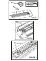
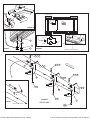
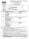
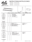
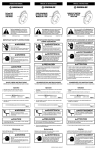
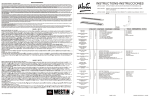
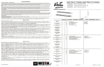
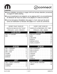
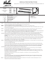
INSTALLATION INSTRUCTIONS
APPLICATION: 2014-UP CHEVY SILVERADO/ GMC SIERRA 1500 SERIES EXT/CREW CAB
AUTOMOTIVE PRODUCTS, INC.
MOUNT KIT
27-2145
SURE-GRIP
OPTIONAL LIGHT KIT
27-6000
ITEM
1
2
3
4
5
6
7
8
9
STEP 1.
QTY
2
6
12
6
6
12
30
12
12
SURE-GRIP
BOARDS
27-6140
27-6145
27-6540
27-6130
27-6135
27-6530
MOLDED
STEP
BOARDS
27-0020
27-0025
27-0010
27-0015
2
1
CONTENTS
STEP BOARD
MOUNT BRACKET
M8-1.25 X 30MM HEX HEAD BOLT
M8-1.25 HEX NUT
M8-1.25 EXTRUDED U-NUT
M8 SQUARE HEAD BOLT
M8 FLAT WASHER
M8 LOCK WASHER
M8 LOCK NUT
TOOLS
13MM SOCKET
13MM WRENCH
RATCHET
TORQUE WRENCH
Remove contents from box and check for damage. Verify all parts are present. Read instructions completely before beginning. It is
strongly recommended to install the Sure Grip Gap Strip for these vehicle applications.
STEP 2. Attach mounting brackets as shown. SEE FIGURE 7 AND 8.
STEP 3. Insert square head bolts as shown (3 per slot, 6 per Step Board/Running Board). SEE FIGURES 2 AND 3.
NOTE: For lighted boards, run wiring harness prior to attaching board to brackets (refer to Step 3). SEE FIGURES 3 AND 5. Run longer
wire harness on passenger side.
STEP 4. For Sure-Grip Running Boards, slide closure strip as shown. Set lights (if purchased) in appropriate location. Attach to Sure-Grip
Running Board as shown. SEE FIGURE 1. Drill hole through plastic strip and run wires as shown. SEE FIGURE 4.
STEP 5. Attach board to brackets as shown. Make sure board and brackets are properly aligned and tighten fasteners. Recommended torque
values are 10 FT.LBS. for 8MM square head fasteners and 23 FT.LBS. for 8MM fasteners. SEE FIGURE 5.
NOTE: For lighted version of Molded Step Board, remove plastic cover from each end of under side of board. Proceed to Steps 6-7.
WARNING: INSTALLING LIGHT HARNESS REQUIRES SPLICING INTO VEHICLES ELECTRICAL SYSTEM. WESTIN RECOMMENDS USING A
PROFESSIONAL FOR THIS INSTALLATION. NOTE: AVOID AREAS OF EXCESSIVE HEAT, VIBRATION, PINCH OR ROTATION WHEN
SECURING HARNESS TO VEHICLE. CAUTION: ALWAYS USE A FUSED(+) POSITIVE SUPPLY SOURCE. UNDERCOAT SEAL FOR HARSH
WEATHER.
HINT: Molded Step Boards: For longevity, check rubber seals before installation. Rubber grommets around red and blue wires going
into rear sockets, should be inserted and recessed about 1/4”. NOTE: Remove bulbs and apply white grease into sockets and replace
bulbs. Apply RTV Silicone where lights go into socket. Install lights and run wire loom as shown. SEE FIGURE 3. For Sure-Grip
Running Boards, run wire loom down center as shown. SEE FIGURE 2.
STEP 6. Determine whether your vehicle has a positive or negative switching courtesy system or an auxiliary light source (most Fords). Obtain
an accurate wiring diagram for your vehicle's courtesy light system.
For positive and negative switching:
Locate a pass-through point (usually under carpet at driver side door sill) for the wire harness. Locate main courtesy wire (usually
wire lead to dome light). NOTE: If you do not use the main courtesy wire, lights will only function when one door is open. Route wire
harness so that the 2 female connections (from step board) are nearest to pass thru point.*Connect opposite step board lead to
either connection. Connect the splicing lead to remaining female socket and route one wire thru pass thru point. SEE FIGURE 6.
VERY IMPORTANT - Double check that your system has positive or negative switching.
For positive switching only: Connect positive wire to main courtesy system, (usually wire lead to dome light). TEST CONTINUITY
BEFORE CONNECTING BY OPENING AND CLOSING ALL DOORS. Ground remaining wire.
For negative switching only: Connect negative wire to main courtesy system, (usually wire lead to dome light but sometimes from
dome light to courtesy ECU). TEST GROUND CONTINUITY BEFORE CONNECTING BY OPENING AND CLOSING ALL DOORS. Connect
remaining wire to battery using a 5A fuse.
**Be sure that you have not routed any wires near moving parts (i.e.. driveshaft) or near any heat generating source (i.e..
transmission, engine, exhaust).
Auxiliary Light source:
Locate auxiliary light source connection under vehicle (usually attached to back side of front or rear fender well (refer to vehicles
owners manual). SEE FIGURE 6. TEST SOURCE BEFORE CONNECTING. Connect splicing leads to aux light source. test step board
lights for proper function by opening and closing doors.
STEP 7. Under-coat board, brackets and electrical wires, connections and lenses for harsh weather conditions. Reinstall plastic cover on
underside of Step boards. INSTALLATION IS COMPLETE.
FIGURE 1
6
FIGURE 2
6
FIGURE 3
TO INSIDE ACCESS
BLACK
FORWARD
RED
FIGURE 4
BLACK
10 AMP FUSE
+
6
-
SPLICE
BLACK WIRE
TO GRND
RED WIRE
GROUND (black wire)
POSITIVE LEAD (red wire)
7
9
FIGURE 5
FIGURE 6
DOOR SILL COVER REMOVED
4 7 8
4 7 8
5
FO
7 8 3
RW
AR
D
4 7 8
2
7 8 3
REMOVE RUBBER PLUG
5
3 7
7 8 3
2
FIGURE 7
FIGURE 8
3 7
2
DRIVER SIDE
REAR MOUNT LOCATION
Get top quality Westin products on our website.
3 7
If you’re looking for quality running boards, visit our website.