1
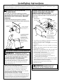
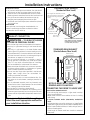
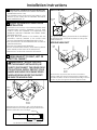
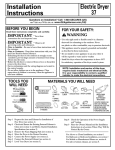
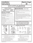
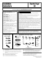
Installation
Instructions
Electric Dryer
10
Questions on Installation? Call: 1-800-GECARES (US)
or Visit our Web site at: www.GEAppliances.com (US)
BEFORE YOU BEGIN
WARNING RISK OF FIRE
Read these instructions completely and
carefully.
•IMPORTANT- Save these instructions
for local inspector’s use.
•IMPORTANT- Observe all governing
codes and ordinances.
• Note to Installer - Be sure to leave these
instructions with the customer.
• Note to Customer - Keep these instructions
with your Use and Care Book for future
reference.
• Before the old dryer is removed from service
or discarded, remove the dryer door.
• Service information and the wiring diagram
are located in the control console.
• Do not allow children on or in the appliance.
Close supervision of children is
necessary when the appliance is used
near children.
• Install the dryer where the temperature
is above 50°F for satisfactory operation of
the dryer control system.
TOOLS YOU
WILL NEED
SLIP JOINT PLIERS
FLAT BLADE SCREWDRIVER
• To reduce the risk of severe injury or death, follow all installation
instructions.
• Clothes dryer installation must be performed by a qualified installer.
• Install the clothes dryer according to these instructions and in
accordance with local codes.
• This dryer must be exhausted to the outdoors.
• Use only rigid metal 4” diameter ductwork inside the dryer cabinet and use
only UL approved transition ducting between the dryer and the home duct.
• DO NOT install a clothes dryer with flexible plastic ducting materials. If
flexible metal (semi-rigid or foil-type) duct is installed, it must be UL listed
and installed in accordance with the instructions found in “Connecting
The Dryer To House Vent” on pages 4-5 of this manual. Flexible venting
materials are known to collapse, be easily crushed, and trap lint. These
conditions will obstruct dryer airflow and increase the risk of fire.
• Do not install or store this appliance in any location where it could be
exposed to water and or weather.
• Save these instructions. (Installers: Be sure to leave these instructions
with the customer).
NOTE: Installation and service of this dryer requires basic
mechanical and electrical skills. It is your responsibility to
contact a qualified installer to make the electrical connections.
MATERIALS YOU WILL NEED
4" DIA. METAL DUCT
(RECOMMENDED)
4" DIA. FLEXIBLE METAL (SEMI-RIGID)
UL LISTED TRANSITION DUCT
(IF NEEDED)
KIT WX08X10077 (INCLUDES 2 ELBOWS)
4" DUCT
CLAMPS (2)
OR
4" SPRING
CLAMPS (2)
4" DIA. ME TAL
ELBOW
EXHAUST
HOOD
PHILLIPS SCREWDRIVER
4" DIA. FLEXIBLE METAL (FOIL TYPE)
UL LISTED TRANSITION DUCT
(IF NEEDED.)
LEVEL
Step 1 Prepare the area and exhaust for installation of new dryer
(see section 1).
Step 2 Check and ensure the existing external exhaust is clean (see
section 1) and meets attached installation specifications (see
section 3).
Step 3 Remove the foam shipping pads (see section 1).
Step 4 Move the dryer to the desired location.
Step 5 Connect the power supply (see section 2).
Step 6 Connect the external exhaust (see section 4).
DUCT TAPE
GLOVES
SAFETY
GLASSES
3/4" STRAIN
RELIEF
UL RECOGNIZED
DRYER POWER
CORD KIT
(NOT PROVIDED
WITH DRYER)
UL RATED
120/240V,30A
WITH 3 OR 4 PRONGS.
IDENTIFY THE PLUG
TYPE AS PER THE
HOUSE RECEPTACLE
BEFORE PURCHASING
LINE CORD.
4” COVER PLATE (IF NEEDED
(KIT WE1M454)
Step 7 Level your dryer (see section 5).
Step 8 Check the operation of the power supply and venting.
Step 9 Place the owners manual and the installation instructions in
a location where they will be noticed by the owner.
For alcove or closet installation, see section 6.
For bathroom or bedroom installation, see section 7.
For mobile or manufactured home, see section 8.
For side or bottom exhaust, see section 9.
31-16629-1 03-11 GE
234D1052P003
Installation Instructions
Minimum Clearance Other Than Alcove or Closet Installation
Minimum clearance to combustible surfaces and for air opening are: 0 in. clearance both sides, 1 in. front and 3 in. rear.
Consideration must be given to provide adequate clearance for installation and service.
CONNECTING DRYER USING 4-WIRE
CONNECTION (MUST BE USED FOR
MOBILE HOME INSTALLATION)
1 PREPARING FOR INSTALLATION
OF NEW DRYER
TIP: Install your dryer before installing your washer.
This will allow better access when installing dryer exhaust.
NOTE: Since January 1,1996, the National Electric code requires
that the new constructions utilize a 4-wire connection to an
electric dryer.
REMOVING LINT FROM WALL EXHAUST
OPENING
REMOVE GROUND STRAP
AND DISCARD. KEEP GREEN
GROUND SCREW
• Remove and discard existing plastic or metal foil
transition duct and replace with UL listed transition duct.
HOT
WIRE
L1
WALL
INTERNAL DUCT
OPENING
SCREWS
(3)
CHECK TH AT EXHAUST
HOOD DAMPER OPENS
AND CLOSES FREE LY.
N
RELOC ATE GREEN
GROUND SCREW
HERE
GREEN OR
YELLOW WIRE
STRAIN
RELIEF
BRACKET
L2
NEUTRAL
(White)
HOT
WIRE
TILT THE DRYER SIDEWAYS
AND REMOVE THE FOAM
SHIPPING PADS BY
PULLING AT THE SIDES
AND BREAKING THEM
AWAY FROM THE DRYER
LEGS. BE SURE TO
REMOVE ALL OF THE
FOAM PIECES AROUND
THE LEGS.
COVER
3/4", UL
RECOGNIZED
STRAIN RELIEF
4 #10 AWG MINIMUM COPPER
CONDUCTORS OR 120/240V 30A POWER
SUPP LY CORD KIT MARKED FOR USE
WITH D RYERS & PROVIDED WITH
CLOSED LOOP OR S PADE TERMINALS
WITH UPTURNED ENDS (NOT SUPPLIED).
1. Turn off the circuit breaker (s) (30 amp) or remove the
dryer’s circuit fuse at the electrical box.
2. Be sure the dryer cord is unplugged from the wall
receptacle.
3. Remove the power cord cover located at the lower
back.
4. Remove and discard ground strap. Keep the green
ground screw for step 7.
5. Install 3/4 in. UL recognized strain relief to power cord
entry hole. Bring power cord through strain relief.
6. Connect power cord as follows:
A. Connect the 2 hot lines to the outer screws of
the terminal block (marked L1 and L2).
B. Connect the neutral (white) line to the center of
the terminal block (marked N).
7. Attach ground wire of power cord with the green
ground screw (hole above strain relief bracket). Tighten
all terminal block screws (3) completely.
8. Properly secure power cord to strain relief.
9. Reinstall the cover.
2 ELECTRICAL CONNECTION INFORMATION
WARNING - TO REDUCE THE RISK OF
FIRE, ELECTRICAL SHOCK AND PERSONAL INJURY:
• DO NOT USE AN EXTENSION CORD OR AN
ADAPTER PLUG WITH THIS APPLIANCE.
Dryer must be electrically grounded in accordance with
local codes and ordinances, or in the absence of local
codes, in accordance with the NATIONAL ELECTRICAL
CODE, ANSI/NFPA NO. 70.
WARNING: NEVER LEAVE THE
ELECTRICAL REQUIREMENTS
This dryer must be connected to an individual branch
circuit, protected by the required time-delay fuses or
circuit breakers. A four or three-wire, single phase,
120/240V or 120/208V, 60Hz, 30 amp circuit is required.
COVER OFF OF THE TERMINAL BLOCK.
GROUNDING INSTRUCTIONS
This dryer must be connected to a grounded metal, permanent wiring system, or an equipment-grounding conductor
must be run with the circuit conductors and connected to
the equipment grounding terminal on the appliance.
2
Installation Instructions
CONNECTING DRYER USING 3-WIRE
CONNECTION
IF REQUIRED, BY LOCAL CODE,
INS TALL EXTERNAL GROUND
(NOT PROVIDED) TO GROUNDED
ME TAL, COLD WATER PIPE, OR
OTHER ES TABLISHED GROUND
DETERMINED BY A QUALIFIED
ELECTRICIAN.
GREEN
GROUND
SCREW
3 EXHAUST INFORMATION
WARNING - IN CANADA AND IN THE
UNITED STATES, THE REQUIRED EXHAUST
DUCT DIAMETER IS 4 in (102mm). DO NOT USE
DUCT LONGER THAN SPECIFIED IN THE EXHAUST LENGTH TABLE.
GROUND
STRAP
HOT
WIRE
STRAIN RELIEF
BRACKET
Using exhaust longer than specified length will:
• Increase the drying times and the energy cost.
• Reduce the dryer life.
• Accumulate lint, creating a potential fire hazard.
The correct exhaust installation is YOUR
RESPONSIBILITY. Problems due to incorrect installation
are not covered by the warranty.
Remove and discard existing plastic or metal foil
transition duct and replace with UL listed transition duct.
The MAXIMUM ALLOWABLE duct length and number of
bends of the exhaust system depends upon the type of
duct, number of turns, the type of exhaust hood (wall
cap), and all conditions noted below. The maximum duct
length for rigid metal duct is shown in the table below.
L1
SCREWS
(3)
NEUTRAL
(White)
COVER
3/4", UL
RECOGNIZED
STRAIN RELIEF
L2
HOT
WIRE
3 #10 AWG MINIMUM COPPER
CONDUCTORS OR 120/240V 30A POWER
SUPP LY CORD KIT MARKED FOR USE
WITH D RYERS & PROVIDED WITH CLOSED
LOOP OR S PADE TERMINALS WITH
UPTURNED ENDS (NOT SUPPLIED).
EXHAUST LENGTH
RECCOMMENDED MAX. LENGTH
Exhaust Hood Types
1. Turn off the circuit breaker(s) (30 amp) or remove the
dryer’s circuit fuse at the electrical box.
2. Be sure the dryer cord is unplugged from the wall.
3. Remove the power cord cover located at the lower
back.
4. Install 3/4 in. UL recognized strain relief to power cord
entry hole. Bring power cord through strain relief.
5. Connect power cord as follows:
A. Connect the 2 hot lines to the outer screws of the
terminal block (marked L1 and L2).
B. Connect the neutral (white) line to the center of
the terminal block (marked N).
6. Be sure ground strap is connected to neutral (center)
terminal of block and to green ground screw on cabinet
rear. Tighten all terminal block screws (3) completely.
7. Properly secure power cord to strain relief.
8. Reinstall the cover.
4" DIA.
4" DIA.
4"
No . of 90º
Elbows
0
1
2
3
4
Rigid
Metal
90
60
45
35
25
Feet
Feet
Feet
Feet
Feet
EXHAUST SYSTEM CHECK LIST
HOOD OR WALL CAP
• Terminate in a manner to prevent back drafts or entry of
birds or other wildlife.
• Termination should present minimal resistance to
the exhaust air flow and should require little or no
maintenance to prevent clogging.
• Never install a screen in or over the exhaust duct. This
could cause lint build up.
• Wall caps must be installed at least 12 in. above ground level
or any other obstruction with the opening pointed down.
SEPARATION OF TURNS
For best performance, separate all turns by at least 4 ft.
of straight duct, including distance between last turn and
exhaust hood.
TURNS OTHER THAN 90º
• One turn of 45º or less may be ignored.
• Two 45º turns should be treated as one 90º turn.
• Each turn over 45º should be treated as one 90º turn.
WARNING: NEVER LEAVE THE
COVER OFF OF THE TERMINAL BLOCK.
3
Installation Instructions
STANDARD REAR EXHAUST
(Vented at floor level)
SEALING OF JOINTS
• All joints should be tight to avoid leaks. The male end of
each section of duct must point away from the dryer.
• The duct shall not be assembled with screws or other
fastening means that extend into the duct and catch lint.
• Duct joints can be made air and moisture-tight by
wrapping the overlapped joints with duct tape.
• Horizontal runs should slope down toward the outdoors
1/2 inch per foot.
INSULATION
Duct work that runs through an unheated area or is
near air conditioning should be insulated to reduce
condensation and lint build-up.
For straight line installation, connect
the dryer exhaust to the external
exhaust hood using duct tape or
clamp.
EXTERNAL DUCT
OPENING
DUCT TAPE OR
DUCT CLAMP
4" METAL DUCT CUT
TO PROPER LENGTH
DUCT TAPE OR
DUCT CLAMP
4 EXHAUST CONNECTION
NOTE: WE STRONGLY RECOMMEND SOLID
METAL EXHAUST DUCTING. HOWEVER, IF
FLEXIBLE DUCTING IS USED IT MUST BE
UL-LISTED METAL, NOT PLASTIC.
WARNING - TO REDUCE THE RISK
OF FIRE OR PERSONAL INJURY:
• This clothes dryer must be exhausted to the outdoors.
• Use only 4” rigid metal ducting for the home exhaust
duct.
• Use only 4” rigid metal or UL-listed flexible metal
(semi-rigid or foil-type) duct to connect the dryer to the
home exhaust duct. It must be installed in accordance
with the instructions found in “Connecting the Dryer to
House Vent” on pages 4-5 of this manual.
• Do not terminate exhaust in a chimney, a wall, a
ceiling, gas vent, crawl space, attic, under an enclosed
floor, or in any other concealed space of a building.
The accumulated lint could create a fire hazard.
• Never terminate the exhaust into a common duct with
a kitchen exhaust system. A combination of grease
and lint creates a potential fire hazard.
• Do not use duct longer than specified in the exhaust
length table. Longer ducts can accumulate lint,
creating a potential fire hazard.
• Never install a screen in or over the exhaust duct. This
will cause lint to accumulate, creating a potential fire
hazard.
• Do not assemble ductwork with any fasteners that
extend into the duct. These fasteners can accumulate
lint, creating a potential fire hazard.
• Do not obstruct incoming or exhausted air.
• Provide an access for inspection and cleaning of the
exhaust system, especially at turns and joints. Exhaust
system shall be inspected and cleaned at least once a
year.
STANDARD REAR EXHAUST
(Vented above floor level)
ELBOW HIGHLY
RECOMMENDED
RECOMMENDED
CONFIGURATION
TO MINIMIZE
EXHAUST
BLOCKAGE.
ELBOW HIGHLY
RECOMMENDED
NOTE: ELBOWS WILL PREVENT DUCT
KINKING AND COLLAPSING.
CONNECTING THE DRYER TO HOUSE VENT
RIGID METAL TRANSITION DUCT
• For best drying performance, a rigid metal transition
duct is recommended.
• Rigid metal transition ducts reduce the risk of crushing
and kinking.
UL-LISTED FLEXIBLE METAL (SEMI-RIGID) TRANSITION
DUCT
• If rigid metal duct cannot be used, then UL-listed flexible
metal (semi-rigid) ducting can be used (Kit WX08X10077).
• Never install flexible metal duct in walls, ceilings, floors or
other enclosed spaces.
• Total length of flexible metal duct should not exceed 8
feet (2.4m).
There are multiple installation options.
Select the most appropriate method for
your installation situation.
4
Installation Instructions
5 LEVELING AND STABILIZING YOUR
• For many applications, installing elbows at both the dryer
and the wall is highly recommended (see illustrations
below). Elbows allow the dryer to sit close to the wall
without kinking and or crushing the transition duct,
maximizing drying performance.
• Avoid resting the duct on sharp objects.
DRYER
Stand the dryer upright near the final location and adjust
the 4 leveling
the corners,
ensure
thatand
theadjust
dryer
Stand thelegs,
dryeratupright
near thetofinal
location
4 leveling
the corners,
ensure that the dryer
is levelthe
from
side tolegs,
sideatand
front to to
rear.
is level from side to side and front to rear.
UL-LISTED FLEXIBLE METAL (FOIL-TYPE) TRANSITION DUCT
• In special installations, it may be necessary to connect
the dryer to the house vent using a flexible metal (foiltype) duct. A UL-listed flexible metal (foil-type) duct may
be used ONLY in installations where rigid metal or flexible
metal (semi-rigid) ducting cannot be used AND where a 4”
diameter can be maintained throughout the entire length
of the transition duct.
• In Canada and the United States, only the flexible metal
(foil-type) ducts that comply with the “Outline for Clothes
Dryer Transition Duct Subject 2158A” shall be used.
• Never install flexible metal duct in walls, ceilings, floors or
other enclosed spaces.
• Total length of flexible metal duct should not exceed 8 feet
(2.4m).
• Avoid resting the duct on sharp objects.
LEVEL
FRONT-TO-BACK
LEVEL
SIDE-TO-SIDE
DO
4 LEVELING
LEGS
ELBOW
REQUIRED
6 ALCOVE OR CLOSET INSTALLATION
• If your dryer is approved for installation in an alcove or
closet, it will be stated on a label on the dryer back.
• The dryer MUST be vented to the outdoors. See the
EXHAUST INFORMATION sections 3 & 4.
• Minimum clearance between dryer cabinet and adjacent
walls or other surfaces is:
0 in. either side
3 in. front
4 in. rear
• Minimum vertical space from floor to overhead cabinets,
ceiling, etc. is 52 in.
• Closet doors must be louvered or otherwise ventilated
and must contain a minimum of 60 sq. in. of open area
equally distributed. If the closet contains both a washer
and a dryer, doors must contain a minimum of 120 sq. in.
of open area equally distributed.
NOTE: WHEN THE EXHAUST DUCT IS LOCATED AT THE
REAR OF THE DRYER, MINIMUM CLEARANCE FROM THE
WALL IS 5.5 in.
ELBOWS
REQUIRED
DON’T
DO NOT
SIT DRYER
ON FLEXIBLE
EXHAUST
DO NOT USE
EXCESSIVE
EXHAUST
LENGTH
DO NOT
CRUSH
FLEXIBLE
EXHAUST
AGAINST
WALL
5
Installation Instructions
TAB LOCATION
7 BATHROOM OR BEDROOM INSTALLATION
• The dryer MUST be vented to the outdoors. See EXHAUST
INFORMATION section 3 & 4.
• The installation must conform with local codes or, in the
absence of local codes, with the NATIONAL ELECTRICAL
CODE, ANSI/NFPA NO. 70.
BEND TAB
UP 45 o
8 MOBILE OR MANUFACTURED HOME
INSTALLATION
• Installation must conform to the MANUFACTURED HOME
CONSTRUCTION & SAFETY STANDARD, TITLE 24, PART
32-80 or, when such standard is not applicable, with
AMERICAN NATIONAL STANDARD FOR MOBILE HOME,
ANSI/NFPA NO. 501B.
• The dryer MUST be vented to the outdoors with the
termination securely fastened to the mobile home
structure. (See EXHAUST INFORMATION section 3 & 4).
• The vent MUST NOT be terminated beneath a mobile or
manufactured home.
• The vent duct material MUST BE METAL.
• Do not use sheet metal screws or other fastening devices
which extend into the interior of the exhaust vent.
• See section 2 for electrical connection information.
Through the rear opening, locate the tab in the middle of
the appliance base. Lift the tab to about 45º using a flat
blade screwdriver.
ADDING NEW DUCT
FIXING
HOLE
PORTION "A"
9 DRYER EXHAUST TO RIGHT, LEFT OR
BOTTOM CABINET
WARNING - BEFORE PERFORM-
ING THIS EXHAUST INSTALLATION, BE
SURE TO DISCONNECT THE DRYER FROM
ITS ELECTRICAL SUPPLY. PROTECT YOUR
HANDS AND ARMS FROM SHARP EDGES
WHEN WORKING INSIDE THE CABINET.
BE SURE TO WEAR GLOVES.
RIGHT OR
LEFT SIDE
EXHAUST
Reconnect the cut portion (A) of the duct to the blower
housing. Make sure that the shortened duct is aligned with
the tab in the base. Use the screw saved previously to secure
the duct in place through the tab on the appliance base.
REMOVE
SCREW
AND SAVE.
REMOVE
DESIRED
KNOCKOUT
(ONE ONLY).
Detach and remove the bottom, right or left side knockout
as desired. Remove the screw inside the dryer exhaust duct
and save. Pull the duct out of the dryer.
FIXING HOLE
B
A
13 1/2"
(13 1/4” for bottom venting)
Cut the duct as shown and keep portion A.
6
Installation Instructions
ADDING ELBOW AND DUCT FOR
EXHAUST TO LEFT OR RIGHT SIDE OF
CABINET
ADDING COVER PLATE TO REAR OF
CABINET (SIDES AND BOTTOM EXHAUST)
• Preassemble 4” elbow with 4” duct. Wrap duct tape
around joint.
• Insert duct assembly, elbow first, through the side
opening and connect the elbow to the dryer internal
duct.
CAUTION:
Be sure not to pull or damage the
electrical wires inside the dryer when inserting the duct.
PL ATE
(KIT WE1M454)
Connect standard metal elbows and ducts to complete
the exhaust system. Cover back opening with a plate (Kit
WE1M454) available from your local service provider. Place
dryer in final location.
EXHAUST CAN
BE ADDED TO
LEFT OR RIGHT SIDE
WARNING-NEVER LEAVE THE
DUCT
TAPE
BACK OPENING WITHOUT THE PLATE.
TO REGISTER YOUR DRYER
CALL TOLL-FREE
1-888-269-1192
• Apply duct tape as shown on the joint between the
dryer internal duct and the elbow.
DUCT
TAPE
Prompt registration confirms your right to protection under
the terms of your warranty.
www.GEAppliances.com (US)
CAUTION:
Use 4” rigid metal ducting only
inside the dryer. Internal duct
joints must be secured with
tape, otherwise they may separate and cause a safety hazard.
For Questions on Installation, Call: 1-800-GECARES (US) or
1-800-361-3400 (Canada).
ADDING ELBOW FOR EXHAUST
THROUGH BOTTOM OF CABINET
• Insert the elbow through the rear opening and connect
it to the dryer internal duct.
• Apply duct tape on the joint between the dryer internal
duct and elbow, as shown on page 6.
CAUTION:
Internal duct joints must be secured with tape,
otherwise they may separate and cause a
safety hazard.
7
Instrucciones
de instalación
Secadora Eléctrica 10
¿Preguntas sobre la instalación? Llame al: 1-800-GECARES (EE.UU.)
o visite nuestro sitio Web en: www.GEAppliances.com (EE.UU.)
ANTES DE COMENZAR
Lea estas instrucciones por completo y con
detenimiento. .
•IMPORTANTE - Guarde estas instrucciones para el uso de inspectores locales.
•IMPORTANTE - Siga todos los códigos
y ordenanzas vigentes.
• Nota al instalador - Asegúrese de dejar
estas instrucciones con el consumidor.
• Nota al consumidor - Mantenga estas
instrucciones con el Manual de uso y
cuidados para referencia futura.
• Antes de que la secadora antigua sea retirada
del servicio o eliminada, quítele la puerta.
• La información sobre reparaciones y el
diagrama del cableado se encuentran en la
consola de control.
• No permita que niños se suban o se metan
dentro del aparato. Se requiere una supervisión estricta cuando el aparato es utilizado
cerca de niños.
• Instale la secadora en lugares donde la
temperatura sea mayor a 50°F para un
funcionamiento satisfactorio del sistema de
control de la secadora.
HERRAMIENTAS
NECESARIAS
ALICATES DE JUNTA DESLIZANTE
DESTORNILLADOR PLANO
DESTORNILLADOR DE ESTRELLA
NIVEL
ADVERTENCIA RIESGO DE INCENDIO
• Para reducir el riesgo de una lesión grave o de muerte, cumpla con
todas las instrucciones de instalación.
• La instalación de la secadora debe efectuarla un instalador calificado.
• Instale la secadora de ropa de acuerdo con estas instrucciones y en
cumplimiento de los códigos locales.
• Esta secadora debe tener una salida al exterior.
• Utilice sólo un conducto rígido de metal de un diámetro de 4” dentro del
gabinete de la secadora y use sólo un conducto de transición aprobado
por UL entre la secadora y el conducto doméstico.
• NO instale una secadora de ropa con conductos de plástico flexibles.
Si se instala un conducto flexible de metal (semi rígido o de tipo papel de
aluminio), debe estar aprobado por UL e instalarse de acuerdo con las
instrucciones de “Cómo conectar la secadora a la ventilación doméstica”
de las páginas 4-5 de este manual. Los materiales de ventilación
flexibles a menudo se desploman, se aplastan y atrapan pelusas. Estas
condiciones obstruyen la corriente de aire de la secadora e incrementan
el riesgo de incendio.
• No instale o almacene este aparato en un lugar donde se vea expuesto
al agua y/o a las inclemencias del tiempo.
• Guarde estas instrucciones. (Instaladores: Asegúrese de dejar estas
instrucciones al consumidor).
NOTA: La instalación y reparación de esta secadora requieren capacidades mecánicas y eléctricas básicas. Es su responsabilidad contactar
a un instalador calificado para realizar las conexiones eléctricas.
MATERIALES NECESARIOS
CONDUCTO DE METAL DE 4” DE DIÁ
(RECOMENDADO)
ABRAZADERAS
CODO DE METAL
DE CONDUCTO DE 4" (2) DE 4” DE DIÁ.
O
ABRAZADERAS
CONDUCTO DE TRANSICIÓN DE METAL
FLEXIBLE (SEMI RÍGIDO) DE 4” DE DIÁ. DE RESORTE DE 4" (2)
APROBADO POR UL (SI FUERA NECESARIO)
KIT WX08X10077 (INCLUYE 2 CODOS)
CONDUCTO DE TRANSICIÓN DE METAL
FLEXIBLE (TIPO PAPEL DE ALUMINIO) DE 4” DE DIÁ.
APROBADO POR UL (SI FUERA NECESARIO)
Paso 1 Prepare el área y la salida para la instalación de la nueva
secadora (ver sección 1).
Paso 2 Verifique y asegúrese de que la salida al exterior existente
esté limpia (ver sección 1) y que cumpla con las especificaciones de instalación incluidas (ver sección 3).
Paso 3 Quite las almohadillas de espuma para envío (ver sección 1).
Paso 4 Desplace la secadora a la ubicación deseada.
Paso 5 Conecte el suministro de energía (ver sección 2).
Paso 6 Conecte la salida al exterior (ver sección 4).
GAFAS
DE SEGURIDAD
KIT DE CABLE
DE ENERGÍA
DE LA SECADORA
(NO PROVISTA CON
LA SECADORA)
ALIVIO DE TENSIÓN CLASIFICADO POR
DE ¾” RECONOCIDO UL 120/240V, 30A
GUANTES
POR UL
CON 3 O 4 CLAVIJAS.
CINTA ADHESIVA
IDENTIFIQUE EL TIPO
PLACA DE CUBIERTA DE 4”
DE ENCHUFE SEGÚN
(SI FUERA NECESARIO)
EL TOMACORRIENTE
(KIT WE1M454)
DE LA VIVIENDA ANTES
DE COMPRAR EL CABLE.
CAMPANA
DE SALIDA
Paso 7 Nivele su secadora (ver sección 5).
Paso 8 Verifique el funcionamiento del suministro de energía y de
la ventilación.
Paso 9 Coloque el manual del propietario y las instrucciones de
instalación en un lugar de fácil acceso para el propietario.
Para instalación en nicho o closet, ver sección 6.
Para instalación en baños o dormitorios, ver sección 7.
Para casas móviles o prefabricadas, ver sección 8.
Para salidas laterales o por la parte inferior, ver sección 9.
31-16629-1 03-11 GE
234D1052P003
Instrucciones de instalación
Espacio mínimo diferente a instalación en nichos o closets
Los espacios libres mínimos respecto de superficies combustibles y de aberturas de aire son: Espacio de 0 pulg. a ambos lados, 1 pulg. en el
frente y 3 pulg. en la parte trasera. Debe tenerse en cuenta un espacio libre adecuado para un funcionamiento y reparación correctos
CÓMO CONECTAR LA SECADORA USANDO UNA CONEXIÓN DE 4 CABLES (DEBE
UTILIZARSE EN INSTALACIONES DE CASAS
MÓVILES)
1 PREPARACIÓN PARA LA INSTALACIÓN
DE UNA SECADORA NUEVA
CONSEJO: Instale su secadora antes de instalar la lavadora. Esto permitirá un mejor acceso cuando instale la
salida de la secadora.
NOTA: Desde el 1 de enero de 1996, el Código Eléctrico Nacional
exige que las nuevas construcciones utilicen una conexión de 4
cables a una secadora eléctrica.
CÓMO QUITAR PELUSA DE LA ABERTURA
DE LA SALIDA DE LA PARED
QUITE LA CINTA DE
CONEXIÓN A TIERRA
Y DESCÁRTELA. CONSERVE
EL TORNILLO VERDE
DE CONEXIÓN A TIERRA
• Quite y descarte el conducto de transición existente de
plástico o de papel de aluminio y coloque un conducto
de transición aprobado por UL.
CABLE
VIVO VUELVA A COLOCAR
EL TORNILLO VERDE
DE CONEXIÓN A TIERRA AQUÍ
L1
PARED
ABERTURA DE
CONDUCTO INTERNA
N
TORNILLOS
(3)
VERIFIQUE QUE
EL REGULADOR
DE TIRO DE LA CAMPANA
DE SALIDA SE ABRA
Y CIERRE LIBREMENTE
SOPORTE
DE ALIVIO
BRACKET
NEUTRAL
(blanco)
CABLE
VIVO
INCLINE LA SECADORA
DE COSTADO Y QUITE
LAS ALMOHADILLAS
DE ESPUMA PARA ENVÍO
TOMÁNDOLAS DE LOS
COSTADOS Y
ARRANCÁNDOLAS DE LAS
PATAS DE LA SECADORA.
ASEGÚRESE DE QUITAR
TODAS LAS PIEZAS
DE ESPUMA UBICADAS
ALREDEDOR DE LAS PATAS.
TAPA
ALIVIO DE TENSIÓN
DE ¾” RECONOCIDO
POR UL
4 CONDUCTORES DE COBRE #10 AWG
MÍNIMO O KIT DE CABLE DE SUMINISTRO
DE ENERGÍA DE 120/240V 30A MARCADO
PARA USO EN SECADORAS Y PROVISTO
CON TERMINALES DE BUCLE CERRADO O
DE PALA CON EXTREMOS HACIA ARRIBA
(NO PROVISTOS).
1. Desactive el interruptor de circuitos (30 amperios) o
quite el fusible del circuito de la secadora de la caja
eléctrica.
2. Verifique que el cable de la secadora esté desenchufado
del tomacorriente.
3. Quite la tapa del cable de energía ubicada en la parte
trasera inferior.
4. Quite y descarte la cinta de conexión a tierra. Conserve
el tornillo verde de conexión a tierra para el paso 7.
5. Instale un alivio de tensión de ¾ pulgadas reconocido
por UL en el orificio de entrada del cable de energía.
Pase el cable de energía a través del alivio de tensión.
6. Conecte el cable de energía de la siguiente manera:
A. Conecte los dos cables vivos a los tornillos externos
del bloque terminal (marcado L1 y L2).
B. Conecte el cable neutral (blanco) al centro del bloque
terminal (marcado N).
7. Conecte el cable a tierra del cable de energía con el
tornillo verde de conexión a tierra (orificio sobre el
soporte de alivio de tensión). Ajuste por completo todos
los tornillos (3) del bloque terminal.
8. Ajuste bien el cable de energía al alivio de tensión.
9. Vuelva a instalar la tapa.
2 INFORMACIÓN SOBRE CONEXIONES
ELÉCTRICAS
ADVERTENCIA - PARA REDUCIR EL
RIESGO DE INCENDIO, DESCARGA ELÉCTRICA
Y LESIONES PERSONALES:
• NO UTILICE UN CABLE DE EXTENSIÓN O UN
ENCHUFE ADAPTADOR CON ESTE APARATO.
La secadora debe contar con una conexión eléctrica a
tierra en cumplimiento con los códigos y ordenanzas
locales, o si éstos no existieran, de acuerdo con el
CÓDIGO ELÉCTRICO NACIONAL, ANSI/NFPA Nº. 70.
REQUISITOS ELÉCTRICOS
Esta secadora debe conectarse a un circuito derivado
individual, con la protección de los fusibles de tiempo
retardado o interruptores de circuito requeridos. Se requiere
un circuito de tres o cuatro cables, fase única, 120/240V ó
120/208V, 60Hz y 30 amperios.
ADVERTENCIA: NUNCA OL-
INSTRUCCIONES DE CONEXIÓN A TIERRA
Esta secadora debe conectarse a un sistema de cableado
permanente con conexión a tierra o debe utilizarse un conductor de conexión a tierra del equipamiento con los conductores de circuito y conectarse a la terminal de conexión
a tierra del aparato.
L2
CABLE VERDE
O AMARILLO
VIDE DE VOLVER A COLOCAR LA TAPA DEL
BLOQUE TERMINAL.
2
Instrucciones de instalación
CÓMO CONECTAR LA SECADORA UTILIZANDO UNA CONEXIÓN DE 3 CABLES
SI ASÍ LO REQUIRIERAN LOS CÓDIGOS
LOCALES, INSTALE UNA CONEXIÓN
A TIERRA EXTERNA (NO PROVISTA)
A METAL CON CONEXIÓN A TIERRA,
TUBERÍAS DE AGUA FRÍA CON CONEXIÓN
A TIERRA U OTRA CONEXIÓN A TIERRA
ESTABLECIDA POR UN ELECTRICISTA
CALIFICADO.
TORNILLO
VERDE
DE CONEXIÓN
A TIERRA
TORNILLOS
(3)
3 INFORMACIÓN DE SALIDA
ADVERTENCIA – EN CANADÁ Y
LOS ESTADOS UNIDOS, EL DIÁMETRO
DE CONDUCTO DE SALIDA REQUERIDO
ES DE 4 PULG. (102 mm). NO UTILICE UN
CONDUCTO DE UNA LONGITUD MAYOR
A LA ESPECIFICADA EN LA TABLA DE
LONGITUD DE SALIDA.
CINTA DE CONEXIÓN
A TIERRA
CABLE VIVO
SOPORTE
DE ALIVIO
DE TENSIÓN
L1
L2
ALIVIO DE TENSIÓN
DE ¾” RECONOCIDO
POR UL
Al utilizar una salida de mayor longitud a la especificada se:
• Incrementarán los tiempos de secado y el costo de energía.
• Reducirá la vida útil de la secadora.
• Acumulará pelusa, lo que podría generar un riesgo
potencial de incendio.
La correcta instalación de salida es SU
RESPONSABILIDAD. Los problemas generados por una
instalación incorrecta no se encuentran cubiertos por
la garantía.
Quite y descarte el conducto de transición existente de
plástico o de papel de aluminio y coloque un conducto
de transición aprobado por UL.
La longitud MÁXIMA PERMITIDA del conducto y la
cantidad de codos del sistema de salida dependen
del tipo de conducto, la cantidad de curvas, la clase
de campana de salida (cubierta de pared) y todas las
condiciones indicadas a continuación. La longitud
máxima del conducto para conductos rígidos de metal
se indica en la siguiente tabla.
NEUTRAL
CABLE VIVO
(blanco)
TAPA
3 CONDUCTORES DE COBRE #10 AWG
MÍNIMO O KIT DE CABLE DE SUMINISTRO
DE ENERGÍA DE 120/240V 30A MARCADO
PARA USO EN SECADORAS Y PROVISTO
CON TERMINALES DE BUCLE CERRADO O
DE PALA CON EXTREMOS HACIA ARRIBA
(NO PROVISTOS).
1. Desactive el interruptor de circuitos (30 amperios) o
quite el fusible del circuito de la secadora de la caja
eléctrica.
2. Verifique que el cable de la secadora esté
desenchufado del tomacorriente.
3. Quite la tapa del cable de energía ubicada en la parte
trasera inferior.
4. Instale un alivio de tensión de ¾ pulgadas reconocido
por UL en el orificio de entrada del cable de energía.
Pase el cable de energía a través del alivio de tensión.
5. Conecte el cable de energía de la siguiente manera:
A. Conecte los dos cables vivos a los tornillos externos
del bloque terminal (marcado L1 y L2).
B. Conecte el cable neutral (blanco) al centro del bloque
terminal (marcado N).
6. Asegúrese de que la cinta de conexión a tierra esté
conectada a la terminal neutral (central) del bloque
y al tornillo verde de conexión a tierra de la parte
trasera del gabinete. Ajuste por completo todos los
tornillos (3) del bloque terminal.
7. Ajuste bien el cable de energía al alivio de tensión.
8. Vuelva a instalar la tapa.
LONGITUD DE SALIDA
LONGITUD MÁXIMA RECOMENDADA
Tipos de campana de salida
4" DIA.
4" DIA.
4"
Cantidad de codos
de 90 grados
0
1
2
3
4
Metal
rígido
90
60
45
35
25
Feet
Feet
Feet
Feet
Feet
LISTA DE CONTROL DEL SISTEMA DE SALIDA
CAMPANA O CUBIERTA DE PARED
• Instale la salida de modo de evitar contracorrientes o el
ingreso de pájaros u otros insectos o animales.
• La boca de salida debe presentar una resistencia
mínima al flujo de salida y debe requerir poco o ningún
mantenimiento para evitar las obstrucciones.
• Nunca instale un filtro dentro o sobre el conducto de
salida. Esto podría provocar una acumulación de pelusa.
• Las cubiertas de pared deben instalarse por lo menos a
12” sobre el nivel del suelo o cualquier otra obstrucción
con la abertura apuntando hacia abajo.
SEPARACIÓN DE CURVAS
Para un mejor desempeño, separe todas las curvas con por
lo menos 4 pies de conducto recto, incluyendo la distancia
entre la última curva y la campana de salida.
GIROS QUE NO SON DE 90°
• Un giro de 45º o menos puede ignorarse.
• Dos giros de 45º deben tratarse como un giro de 90º.
• Todos los giros de más de 45º deben tratarse como un giro de 90º.
ADVERTENCIA: NUNCA OLVIDE DE VOLVER A COLOCAR LA
TAPA DEL BLOQUE TERMINAL.
3
Instrucciones de instalación
SALIDA TRASERA ESTÁNDAR
(Ventilación a nivel del suelo)
SELLADO DE JUNTAS
• Todas las juntas deben estar bien selladas para evitar pérdidas.
El extremo macho de cada sección de conducto debe apuntar
en dirección opuesta a la secadora.
• El conducto no deberá instalarse con tornillos u otros medios de
sujeción que se extiendan dentro del conducto y enganchen
pelusas.
• Las juntas de los conductos deben ser herméticas al aire y a
la humedad mediante la superposición de juntas con cinta
aislante.
• Los tramos horizontales deben tener una inclinación hacia el
exterior de ½” por pie.
Para una instalación en línea recta, conecte
la salida de la secadora a la campana
de salida al exterior con cinta aislante
o una abrazadera.
ABERTURA DE
CONDUCTO EXTERIOR
CINTA AISLANTE
O ABRAZADERA
DE CONDUCTO
AISLACIÓN
Los conductos instalados a través de una área sin calefacción o
ubicados cerca de un acondicionador de aire deben aislarse para
reducir la condensación y la acumulación de pelusas.
CONDUCTO DE METAL
DE 4” CORTADO
CON LA LONGITUD ADECUADA
CINTA AISLANTE O
ABRAZADERA DE CONDUCTO
4 CONEXIÓN A LA SALIDA
NOTA: RECOMENDAMOS ENFÁTICAMENTE EL USO
DE CONDUCTOS DE SALIDA DE METAL SÓLIDO.
SIN EMBARGO, SI SE USAN CONDUCTOS FLEXIBLES,
ÉSTOS DEBEN SER DE METAL APROBADOS POR UL,
NO DE PLÁSTICO.
ADVERTENCIA - PARA
REDUCIR EL RIESGO DE INCENDIO O
DE LESIONES PERSONALES:
• Esta secadora de ropa debe tener una salida al
exterior.
• Utilice sólo un conducto de metal rígido de 4” para el
conducto de salida doméstico.
• Use sólo un conducto de metal rígido de 4” o de
metal flexible (semi rígido o de tipo papel de aluminio)
aprobado por UL para conectar la secadora al
conducto de salida doméstico. Debe instalarse de
acuerdo con las instrucciones incluidas en “Cómo
conectar la secadora a la ventilación doméstica” de
las páginas 4-5 de este manual.
• No instale la boca de salida dentro de una chimenea,
pared, cielorraso, ventilación de gas, espacio entre
pisos, ático, bajo un piso con cerramiento o en
cualquier otro espacio oculto de un edificio. La
acumulación de pelusas podría provocar un riesgo
de incendio.
• Nunca instale la boca de salida dentro de un conducto
común con el sistema de salida de la cocina. La
combinación de grasa y pelusas podría provocar un
riesgo de incendio.
• No utilice un conducto de una longitud mayor a la
especificada en la tabla de longitud de salida. Los
conductos más largos acumulan pelusa, lo que
genera un riesgo potencial de incendio.
• Nunca instale un filtro dentro o sobre el conducto de
salida. Esto provocará la acumulación de pelusas, lo
que genera un riesgo potencial de incendio.
• No arme la red de conductos con sujeciones que
se extiendan dentro del conducto. Estas sujeciones
pueden acumular pelusa, lo que genera un riesgo
potencial de incendio.
• No obstruya el aire que entra y sale.
• Incluya un acceso para inspección y limpieza del
sistema de salida, especialmente en las curvas y
juntas. El sistema de salida debe inspeccionarse y
limpiarse por lo menos una vez al año.
SALIDA TRASERA ESTÁNDAR
(Ventilación sobre el nivel del suelo)
SE RECOMIENDA
EL USO DE CODOS
CONFIGURACIÓN
RECOMENDADA
PARA MINIMIZAR
LAS OBSTRUCCIONES
DE LA SALIDA.
SE RECOMIENDA
EL USO DE CODOS
NOTA: LOS CODOS EVITAN QUE LOS
CONDUCTOS SE DOBLEN O CAIGAN.
CÓMO CONECTAR LA SECADORA A LA VENTILACIÓN DOMÉSTICA
CONDUCTO DE TRANSICIÓN DE METAL RÍGIDO
• Para un mejor desempeño de secado, se recomienda un
conducto de transición de metal rígido.
• Los conductos de transición de metal rígidos reducen el
riesgo de aplastamientos y torceduras.
CONDUCTO DE TRANSICIÓN DE METAL FLEXIBLE
(SEMI-RÍGIDO) APROBADO POR UL
• Si no puede utilizarse un conducto de metal rígido, entonces puede usarse un conducto de metal flexible (semi-rígido)
aprobado por UL (Kit WX08X10077).
• Nunca instale conductos de metal flexibles en paredes,
cielorrasos, pisos u otros espacios cerrados.
• La longitud total del conducto de metal flexible no deberá
superar los 8 pies (2.4 m).
Existen opciones múltiples de instalación.
Seleccione el método más apropiado para su
instalación.
4
Instrucciones de instalación
5 CÓMO NIVELAR Y ESTABILIZAR SU
• Para muchas aplicaciones, se recomienda enfáticamente
la instalación de codos en la secadora y en la pared
(ver ilustraciones de abajo). Los codos permiten que la
secadora se ubique cerca de la pared sin torcer o aplastar
el conducto de transición, lo que potencia al máximo el
desempeño de secado.
• No coloque el conducto sobre objetos afilados.
SECADORA
Coloque la secadora en posición vertical cerca de la
ubicación definitiva y ajuste las cuatro patas de nivelación,
en los extremos,
paraupright
garantizar
que
secadora
Stand the dryer
near the
finallalocation
and se
adjust
encuentre
de lado
lado ytodel
frente
la parte
the 4nivelada
leveling legs,
at theacorners,
ensure
thata the
dryer
trasera.
is level from side to side and front to rear.
CONDUCTO DE TRANSICIÓN DE METAL FLEXIBLE (SEMIRÍGIDO) APROBADO POR UL
• En instalaciones especiales, puede ser necesario conectar la
secadora a la ventilación doméstica utilizando un conducto
de metal flexible (tipo papel de aluminio). Puede utilizarse
un conducto de metal flexible (tipo papel de aluminio)
aprobado por UL SÓLO en instalaciones en las que no
pueden usarse conductos de metal rígidos o flexibles (semirígidos) Y en las que puede mantenerse un diámetro de 4” a
lo largo de todo el conducto de transición.
• En Canadá y los Estados Unidos, solamente deberán
utilizarse los conductos de metal flexibles (tipo papel de
aluminio) que cumplan con el “Resumen para conductos
de transición para secadoras de ropa, Tema 2158A”.
• Nunca instale conductos de metal flexibles en paredes,
cielorrasos, pisos u otros espacios cerrados.
• La longitud total del conducto de metal flexible no deberá
superar los 8 pies (2.4 m).
• No coloque el conducto sobre objetos afilados.
NIVELAR
FRENTE A PARTE TRASERA
QUÉ
ACER
NIVELAR
LADO A LADO
4 PATAS
DE NIVELACIÓN
6 INSTALACIÓN EN NICHO O EN CLOSET
CODO
NECESARIO
• Su secadora puede instalarse en un nicho o closet,
como se indica en la etiqueta de la parte trasera del
aparato.
• Esta secadora DEBE tener una ventilación al exterior.
Ver la INFORMACIÓN SOBRE SALIDA secciones 3 y 4.
• El espacio libre mínimo entre el gabinete de la
secadora y las paredes adyacentes u otras superficies
es de:
0 pulg. sobre ambos lados
3 pulg. en el frente
4 pulg. en la parte trasera
CODOS
NECESARIOS
QUÉ NO
HACER
• El espacio vertical mínimo desde el piso a los
gabinetes superiores, cielorraso, etc., es de 52 pulg.
NO COLOQUE
LA SECADORA
SOBRE UNA
SALIDA FLEXIBLE
• Las puertas del closet deben contar con rejillas u
otro tipo de ventilación y deben tener por lo menos
60 pulg. cuadradas de espacio abierto igualmente
distribuido. Si el closet incluye una lavadora y una
secadora, las puertas deben contener un mínimo de
120 pulg. cuadradas de espacio abierto distribuido
uniformemente.
NOTA: CUANDO EL CONDUCTO DE SALIDA ESTÁ
UBICADO EN LA PARTE TRASERA DE LA SECADORA, EL
ESPACIO LIBRE MÍNIMO DESDE LA PARED DEBE SER
5.5 PULGADAS.
NO UTILICE
UNA LONGITUD
DE SALIDA EXCESIVA
NO APLASTE
LA SALIDA
FLEXIBLE
CONTRA
LA PARED
5
Instrucciones de instalación
UBICACIÓN DE LA LENGÜETA
7 INSTALACIÓN EN BAÑOS O DORMITORIOS
• Esta secadora DEBE tener una ventilación al exterior. Ver
la INFORMACIÓN SOBRE SALIDA secciones 3 y 4.
• La instalación debe cumplir con códigos locales o, si no
existieran, con el CÓDIGO ELÉCTRICO NACIONAL, ANSI/
NFPA N° 70.
GIRE LA LENGÜETA
HASTA 45°
8 INSTALACIÓN EN CASAS MÓVILES O
PREFABRICADAS
• La instalación debe cumplir con la NORMA SOBRE
CONSTRUCCIÓN Y SEGURIDAD DE CASAS PREFABRICADAS,
TÍTULO 24, PARTE 32-80 o, cuando dicha norma no sea
aplicable, con la NORMA NACIONAL ESTADOUNIDENSE
PARA CASAS MÓVILES, ANSI/NFPA Nº 501B.
• La secadora DEBE tener ventilación al exterior con la
terminación bien sujeta a la estructura de la casa móvil.
(Ver la INFORMACIÓN SOBRE SALIDA secciones 3 y 4).
• La ventilación NO DEBE terminar debajo de una casa
móvil o prefabricada.
• El material del conducto de ventilación DEBE SER METAL.
• No utilice tornillos para placas de metal u otros
dispositivos de sujeción que se extiendan al interior de la
ventilación de salida.
• Ver la sección 2 sobre información sobre conexiones eléctricas.
A través de la abertura trasera, ubique la lengüeta en
el medio de la base del aparato. Levante la lengüeta
hasta alrededor de 45°, utilizando un destornillador de
lados planos.
CÓMO AGREGAR CONDUCTOS NUEVOS
ORIFICIO
DE MONTAJE
PORCIÓN “A”
9 SALIDA DE LA SECADORA HACIA LA
DERECHA, IZQUIERDA O PARTE INFERIOR DEL GABINETE
ADVERTENCIA - ANTES DE EFECTUAR ESTA INSTALACIÓN DE SALIDA,
ASEGÚRESE DE DESCONECTAR LA SECADORA DEL SUMINISTRO ELÉCTRICO.
PROTEJA SUS MANOS Y BRAZOS DE LOS
LADOS AFILADOS CUANDO TRABAJE
DENTRO DEL GABINETE. ASEGÚRESE DE
USAR GUANTES
SALIDA LATERAL
POR DERECHA O IZQUIERDA
Vuelva a conectar la porción cortada (A) del conducto a la carcasa
del ventilador. Asegúrese de que el conducto más corto se encuentre
alineado con la lengüeta de la base. Utilice el tornillo conservado
con anterioridad para sujetar el conducto en su lugar a través de la
lengüeta de la base del artefacto.
QUITE EL
TORNILLO
Y CONSÉRVELO
QUITE
EL RECORTE
DESEADO (SÓLO UNO)
Despegue y quite el recorte inferior, derecho o izquierdo,
según corresponda. Quite el tornillo ubicado dentro
del conducto de salida de la secadora y consérvelo.
ORIFICIO DE MONTAJE
Saque el conducto de la secadora.
B
A
13 1/2"
(13 1/4” para ventilación inferior)
Corte el conducto como puede verse y conserve la porción A.
6
Instrucciones de instalación
CÓMO AGREGAR CODOS Y CONDUCTOS
DE SALIDA HACIA LA IZQUIERDA O DERECHA DEL GABINETE
CÓMO AGREGAR LA PLACA DE CUBIERTA A
LA PARTE TRASERA DEL GABINETE (SALIDAS
POR LOS LADOS Y LA PARTE INFERIOR)
• Arme previamente un codo de 4” con un conducto de 4”.
Coloque cinta aislante alrededor de la junta.
• Introduzca el montaje del conducto, el codo primero,
a través de la abertura lateral y conecte el codo al
conducto interno de la secadora.
PRECAUCIÓN:
Asegúrese de no tirar o
dañar los cables eléctricos ubicados dentro de la secadora
cuando introduzca el conducto.
PLACA
(KIT WE1M454)
Conecte los codos y conductos de metal estándar para
completar el sistema de salida. Cubra la abertura trasera
con la placa (Kit WE1M454), disponible en su proveedor de
servicios local. Coloque la secadora en su ubicación final.
LA SALIDA PUEDE
AGREGARSE A LOS
LADOS DERECHO
O IZQUIERDO
CINTA
AISLANTE
ADVERTENCIA - NUNCA DEJE
LA ABERTURA TRASERA SIN LA PLACA
EN SU LUGAR.
PARA REGISTRAR SU SECADORA LLAME
EN FORMA GRATUITA
1-888-269-1192
• Aplique cinta aislante como puede verse en la junta
entre el conducto interno de la secadora y el codo.
CINTA
Registrarse rápidamente confirma su derecho de
protección bajo los términos de su garantía.
www.GEAppliances.com (EE.UU.)
PRECAUCIÓN:
Utilice un conducto de metal
rígido de 4” sólo dentro de la
secadora. Las juntas del conducto interno deben sujetarse
con cinta; caso contrario,
pueden separarse y provocar
un riesgo de seguridad.
Para preguntas sobre la instalación, llame al:
1-800-GECARES (EE.UU.) o 1-800-361-3400 (Canadá).
CÓMO AGREGAR UN CODO DE SALIDA A
TRAVÉS DE LA PARTE INFERIOR DEL GABINETE
• Introduzca el codo a través de la abertura trasera y
conéctelo al conducto interno de la secadora.
• Aplique cinta aislante en la junta entre el conducto
interno de la secadora y el codo, como puede verse en
la página 6.
PRECAUCIÓN:
Las juntas del conducto interno deben
sujetarse con cinta; caso contrario, pueden
separarse y provocar un riesgo de seguridad.
7