1
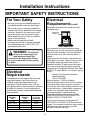
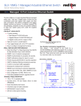
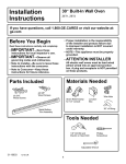
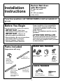
Installation
Instructions
Built-In Wall Oven
with Microwave
27” (68.6 cm) model
JKP90
30” (76.2 cm) models
JTP90, PT970
If you have questions, call 1.800.GE.CARES or visit our website at:
ge.com
Before You Begin
• Proper installation is the responsibility
of the installer and product failure due
to improper installation is NOT covered
under warranty.
• NOTE—This appliance must be properly
grounded.
Read these instructions carefully and completely.
•
IMPORTANT—Save these
instructions for local inspector’s use.
•
IMPORTANT—Observe all
•
governing codes and ordinances.
• Note to Installer—Be sure to leave these
instructions with the consumer.
• Note to Consumer—Keep these
instructions for future reference.
ATTENTION INSTALLER
All electric wall ovens must be hard wired
(direct wired) into an approved junction
box. A plug and receptacle is NOT permitted
on these products.
Materials Needed
Parts Included
(Appearance will vary.)
Wire Nuts
Screws For
Installation
(8-18 x .750
flat head Phillips
wood screws)
Strain Relief Clamp
for 1/2” conduit
27″ (68.6 cm)
Metal Bottom Trim
Junction
Box
36” (91 cm)
of String
Tools Needed
Optional 27″
(68.6 cm) Metal
Bottom Trim
Assembly (on
some models or
can be purchased
separately)
31-10648
30″ (76.2 cm)
Metal Bottom
Trim Assembly
1/8” Drill Bit and
Electric or Hand Drill
02-07 JR
1
Phillips
Screwdriver
Installation Instructions
IMPORTANT SAFETY INSTRUCTIONS
For Your Safety
Electrical
Requirements (cont.)
• Be sure your oven is installed properly by
a qualified installer or service technician.
• Be sure the oven is securely installed in a
cabinet that is firmly attached to the house
structure. Weight on the oven door could
cause the oven to tip and result in injury.
Never allow anyone to climb, sit, stand or
hang on the oven door.
• Make sure the cabinets and wall
coverings around the oven can withstand
the temperatures (up to 200°F [93.3°C])
generated by the oven.
Rating plate is located on the inside wall of the
microwave oven.
Rating Plate
Location
We recommend you have the electrical wiring
and hookup of your oven connected by a qualified
electrician. After installation, have the electrician
show you where your main oven disconnect is
located.
Check with your local utilities for electrical codes
which apply in your area. Failure to wire your oven
according to governing codes could result in a
hazardous condition. If there are no local codes,
your oven must be wired and fused to meet the
requirements of the National Electrical Code, ANSI/
NFPA No. 70–Latest Edition. You can get a copy by
writing:
National Fire Protection Association
Batterymarch Park
Quincy, MA 02269
Effective January 1, 1996, the National
Electrical Code requires that new, but not existing,
construction utilize a four-conductor connection
to an electric oven. When installing an electric oven
in new construction, a mobile home, recreational
vehicle or an area where local codes prohibit
grounding through the neutral conductor,
follow the instructions in the section on NEW
CONSTRUCTION AND FOUR-CONDUCTOR
BRANCH CIRCUIT CONNECTION.
You must use a three-wire, single-phase A.C.
208Y/120 Volt or 240/120 Volt, 60 hertz electrical
system. If you connect to aluminum wiring, properly
installed connectors approved for use with
aluminum wiring must be used.
WARNING: The electrical
power to the oven supply line
must be shut off while line
connections are being made. Failure
to do so could result in serious injury
or death.
Electrical
Requirements
This appliance must be supplied with the proper
voltage and frequency, and connected to an
individual, properly grounded branch circuit,
protected by a circuit breaker or fuse. See the
rating plate located on the oven frame to determine
the rating of the product. Use the chart below to
determine the minimum recommended dedicated
circuit protection.
KW Rating
240V
≤4.8 KW
4.9 KW–7.2 KW
7.3 KW–9.6 KW
9.7 KW–12.0 KW
KW Rating
208V
≤4.1 KW
4.3 KW–6.2 KW
6.3 KW–8.3 KW
8.4 KW–10.4 KW
Recommended
Circuit Size
(Dedicated)
20 Amp
30 Amp
40 Amp
50 Amp
2
Installation Instructions
Pre-Installation Checklist
Door removal is not a requirement for
installation of the product, but is an
added convenience. To remove the door:
Remove packaging materials. Check
inside microwave, behind hinges and
under false bottom. Remove labels on
the outside of the door, plastic on trims
and panel, all tape around the oven
and any shipping screws securing the
oven to the base pad.
Open the oven door as far as it will go.
Push both hinge
locks down toward
Hinge
the door frame,
Hinge
Slot
Slot
to the unlocked
position. This may
require a flat blade
screwdriver.
Hinge
Hinge
Unlocked
Unlocked
Position
Position
Hinge
Hinge
Arm
Arm
DO NOT LIFT THE DOOR
BY THE HANDLE!
Place hands on both sides of
the door, and close the oven
door to the removal position,
which is most of the way closed.
Lift door up and
out until the
hinge arms
clear the slots.
Oven Racks
EASY
INSTA
LLA
TIO
EASY
INSTALLATION
OFNYOUR NEW
Before
30"
IMPOR you begin
WALL OF YO
30"
-Read WALL OVEN
IMPOR TANTOVEN UR NE
Save
these
Note TANTinstru
OBSE these
W
to
instru
Install
ctions
OWNE
RVE instructions
Before
you begin-Read
completely and carefully.
er- Bethese
comp
ALL ctions
Note- R- Keep
for inspector’s
GOVE
these sure
instructions
for local
IMPORTANTletelyuse.
ThisSave these
to leave RNINGlocal inspec and
applia
IMPORTANT- OBSERVE
ALL
GOVERNING
CODES AND ORDIANCES.
instru
carefu
CODE
these
nce
tor’s
ctions
Note to Installer- Be suremust
to leave
these
with
the consumer.
S AND
instru
use. lly.
for instructions
be
ctions
future
ORDIA
OWNER- Keep these instructionsprope
for future
reference.
with
rly grounrefere
FOR
the NCES.
Note- This
appliance must be properly grounded
(if applicable).
nce.
YOUR
consu
ded
SAFE
(if applic
mer.
Before
TY
able).
instru you begin
carefu ctions comp-Read
ELECTRICAL REQUIREMENTS
lly. YOUR SAFETY
IMPORFOR
letely these
and
ELEC
instru TANTTRICA
ctionsyouSave
Before
begin-Read
IMPOR
Before you begin-Read
these these
L REQU these
Before
TANT for local
completely and
GOVEinstructions
IREME
instructions completely
and
instru you begin
RNING - OBSE inspec
NTS
Note carefully.
tor’s
carefully.
RVE
to Install CODE Save
carefu ctions comp-Read
use.
ALL
these IMPORTANTS ANDthese
IMPORTANT- Save these
er- Befor
IMPOR lly.
letely these
instructions
local inspector’s use.
OWNE instru
instructions for localand
inspector’s use.
ctions sure ORDIANCES
instru TANTR-IMPORTANTto leave
OBSERVE
ALL
for future
Keep
with
Save OBSERVE ALL
IMPORTANTctions
.
the AND ORDIANCES. IMPOR
these CODES
these
NoteGOVERNING
refere
instru consu
TANT for localCODES AND ORDIANCES.
GOVE GOVERNING
ctions
prope ThisNote
inspec
- OBSE
tonce.
Installer- Be
sure mer.
to leave
applia
Note to
InstallerBe sure to leave
rly
Note RNING
tor’s
RVE
nce
Before groun
these instructions
with the consumer.
to these CODE
instructionsALL
with theuse.
consumer.
these Install
ded must be
S AND
instru youOWNERKeep
these instructions
er- Be
begin (if
applic
OWNERKeep
these instructions
OWNE instru
sure ORDIA
ctions
-Read
carefu ctionsfor
able).
future
reference.
R- Keep
comp
to leave NCES
for futurewith
reference.
for future
these
.
IMPOR lly. Note- This
letelyappliance
must be
the
Note-these
This appliance
must be
Noterefere
and
instru consumer.
instru TANT-properly grounded
(if applicable). prope This properly
nce. grounded
(if applicable).
Save
ctions
applia
IMPORctions for
Beforethese
you begin-Read these
nceyou begin-Read these
Before
Beforerly groun
local
GOVE TANT- instructions
ded mustcompletely
instructions
and
OBSE inspeccompletely and
instru you begin
(if applicbe
Note RNING carefully.
-Read
CODE RVE ALL tor’s use.
carefully.
carefu ctions comp
to
able).
these Install IMPORTANTS AND
Save these
erIMPOR lly.
letely these
IMPORTANTSave these
OWNE instructionsBe sure ORDIA
andfor local inspector’s use.
instructions
for local
use. TANT instructions
NCESinspector’sinstru
R- Keep
to leave
for future
with
. ALL IMPORctions - Save
IMPORTANTOBSERVE
the
these
IMPORTANTOBSERVE ALL
these
for local
Noterefere
instru consu
GOVERNING
CODES AND ORDIANCES.
GOVE TANTGOVERNING
CODES AND ORDIANCES.
inspec
ctions mer.
prope This appliance.
OBSE
Note RNING
rly groun nceNote to Installer- Be sure to leave
tor’s Be sure to leave
RVE
Note
to InstallerCODE
to
use.
ALL
must instructions with the consumer.
these Install
ded these
S AND
instructions with the consumer.
er- these
(if applicbe
OWNE instructionsBeOWNEROWNER- Keep these instructions
sure ORDIA
Keep these instructions
able).
R- Keep
to leave NCES
for future
with
for future reference.
reference. .
the
thesefor future
Noteconsu
refere
Note- This appliance must be
instruThis
Noteappliance must be
ctions mer.
prope This appliance.
properly grounded (if applicable).
rly groun nce properly grounded (if applicable).
ded must be
(if applic
able).
Literature
Pack
Open oven door and remove literature
pack and oven racks. Open microwave
door and remove shelves and turntable
package.
Hinge Clears Slot
Remove Installation Instructions
from literature pack and read them
carefully before you begin.
Be sure to place all literature,
Owner’s Manual, Installations, etc.
in a safe place for future reference.
NOTE: The oven door is very heavy.
Be sure you have a firm grip before lifting
the oven door off the hinges. Use caution
once the door is removed. Do not lay the
door on its handle. This could cause dents
or scratches.
Place the oven on a table or platform even
with the cutout opening. (Platform must
support 255 lbs. [115 Kg].)
Remove the bottom trim from the top
of the oven. It will be installed at the end
of the installation process. The trim is
wrapped separately and taped to the
top of the unit.
3
Installation Instructions
A
Cutout for 27″ (68.6 cm) Built-In Oven
with Microwave models only
For JKP90 model only.
5” (12.7 cm)
Max. from the
left or right
Junction Box
Cabinet
side
Location
Width
27” (68.6 cm)
Cutout Width
25” (63.5 cm)
Min.
25 1/4” (64.1 cm)
Max.
Allow 1” (2.5 cm)
for overlap of oven
over side edges
of cutout
Allow a minimum of 20”
(50.8 cm) for clearance
to adjacent corners,
drawers, walls, etc.
when door is open
2” x 4”
(5 cm x
10 cm) or
equivalent
runners level
with bottom
of cutout
35” (88.9 cm)
Cutout
Min. Above
Height
base rail
41 1/8”
(104.5 cm) Min.
41 1/4”
(104.8 cm) Max.
Alternate Junction Box
Location (access from
adjacent cabinet may
be required)
5” Min.
(12.7 cm)
20” (50.8 cm)
Allow minimum
1” (2.5 cm) for
overlap of oven
top and bottom
of cutout
Recommended cutout
location from floor
21 5/8” (54.9 cm)
Cabinet Width
27” (68.6 cm)
Recommended
Cutout Location
from Floor
21 5/8” (54.9 cm)
Cutout Depth
23 1/2” (59.7 cm)
Cutout Width
25” (63.5 cm) Min.
25 1/4” (64.1 cm) Max.
Cutout Height
41 1/8” (104.5 cm) Min.
41 1/4” (104.8 cm) Max.
NOTE: If the cabinet does not
have a front frame and the sides
are less than 3/4” (1.9 cm) thick,
shim both sides equally to
establish the cutout width.
2” x 4” (5 cm x 10 cm)
2" x 4" or runners
or equivalent
Equivalent
level
with bottom of
Runners
cutout
If the cabinet does not have a solid bottom,
two braces or runners must be installed
level with the bottom of the cutout to
support the weight of the oven. The
runners and braces must support
255 lbs (115 Kg).
24” (61 24"
cm)
NOTE: If marks, blemishes or the
cutout opening are visible above the
installed oven, it may be necessary to
add wood shims under the runners and
front trim until the marks or opening
are covered.
18”
18"
(45.7 cm)
27"
27”
(68.6 cm)
NOTE: If using equivalent
runners, then the center of the
equivalent runners should be
20 1/2” (52.1 cm).
4
Installation Instructions
A
Cutout for 30″ (76.2 cm) Built-In Oven
with Microwave models only
For JTP90, PT970 models only.
Cabinet
*CABINET
Width
WIDTH
30" cm)
30” (76.2
Allow 11/16” (1.8 cm)
for overlap of oven
ALLOW 11/16"
over side edges of
FOR OVERLAP
OF OVEN
OVER
cutout
Cabinet Width
20” (50.8 cm)
Max.
20"
Cutout
Width
CUTOUT
WIDTH
28 1/2”
28
1/2"
MIN.
(72.4
cm) Min.
28 5/8" MAX.
28 5/8”
(72.8 cm) Max.
Junction Box
JUNCTION BOX
Location
LOCATION
SIDE EDGES
OF CUTOUT.
A MINIMUM
Allow ALLOW
a minimum
of 21”
OF 21" FOR CLEARANCE
(53.3
for clearance
TOcm)
ADJACENT
CORNERS,
to adjacent
corners,
DRAWERS,
WALLS, ETC.
WHEN DOORS
OPENED.
drawers,
walls,ARE
etc.
when door is
open
21"
21” (53.3 cm)
Opening
between
inside
walls
THE OPENING
BETWEEN
must be INSIDE
at
WALLS MUST
least
1/2”
BE A28
LEAST
28 1/2"
WIDE
(72.4
cm)
wide
ALLOW 1" FOR
Allow minimum
1”
OVERLAP
(2.5 cm)OF
for
overlap
OVEN
TOP
of ovenAND
top BOTTOM
and 11⁄4”
CUTOUT.
(3.2 cm)OF
overlap
of
bottom of cutout
Cutout
Height
42 3/16”
(107.2 cm)
Min.
CUTOUT
42 HEIGHT
1/4”
42
3/16"cm)
MIN.
(107.3
42 1/4" MAX.
Max.
28” (71.1
28" cm) Min.
TO to
BOTTOM
OF of
Bottom
JUNCTION BOX
Junction Box
30” (76.2 cm)
Recommended
Cutout Location
from Floor
21 5/8” (54.9 cm)
Cutout Depth
23 1/2” (59.7 cm) Min.
Cutout Width
28 1/2” (72.4 cm) Min.
28 5/8” (72.8 cm) Max.
Cutout Height
42 3/16” (107.2 cm) Min.
42 1/4” (107.3 cm) Max.
NOTE: If the cabinet does
not have a front frame and the
sides are less than 3/4” (1.9 cm)
thick, shim both sides equally
to establish the cutout width.
RECOMMENDED
Recommended cutout
CUTOUT from floor
location
LOCATION
21215/8”
5/8" (54.9 cm)
If the cabinet does not have a solid bottom,
two braces or runners must be installed
level with the bottom of the cutout to
support the weight of the oven. The
runners and braces must support
255 lbs (115 Kg).
CL
2”xx4"4”
2"
or
EQUIVALENT
(5 cm x 10 cm)
RUNNERS
or equivalent
runners level
with bottom
of cutout
NOTE: If marks, blemishes or the
cutout opening are visible above the
installed oven, it may be necessary to
add wood shims under the runners and
front trim until the marks or opening
are covered.
Suitable
Bracing
to Support
Runners
21 5/8”
5/8"
21
OVER CENTERLINE
(54.9
cm)
OF
CABINET
Over Centerline
of Cabinet
5
Installation Instructions
A
Cutout for Built-In Oven with
Microwave models only – Over
a Warming Drawer
For JKP90, JTP90, PT970 models only.
30″ (76.2 cm) Oven with
Microwave Oven (Models
JTP90 and PT970) Over a
Warming Drawer
27″ (68.6 cm) Oven with
Microwave Oven (Model
JKP90) Over a Warming
Drawer
Anti-Tip Block
Against Rear
Wall Per
Warming Drawer
Requirement
3” (7.6 cm)
Min.
Per Warming
Drawer
Requirement
Anti-Tip Block
Against Rear
Wall Per Warming
Drawer Requirement
2” (5.1 cm)
Min.
Per Warming
Drawer
Requirement
1” (2.5 cm) Min. Above Toekick
NOTE: Install the
oven only with
specific models
listed on the label 1” (2.5 cm) Min. Above Toekick
located on top of
the oven.
• When installing a Warming Drawer below
a single or double oven, a separate 120V,
60 Hz, properly grounded receptacle must
be installed. Refer to installation instructions
packed with the Warming Drawer for
specific installation requirements.
NOTE: Additional clearances between cutouts
may be required. Check to be sure the oven
supports above the Warming Drawer location
do not obstruct the required interior depth and
height.
6
Installation Instructions
B
Electrical Connections
ATTENTION INSTALLER
All electric wall ovens must be hard wired
(direct wired) into an approved junction
box. A plug and receptacle is NOT permitted
on these products.
DO NOT shorten the flexible conduit.
The conduit strain relief clamp must be
securely attached to the junction box
and the flexible conduit must be securely
attached to the clamp. If the flexible
conduit will not fit within the clamp, do not
install the oven until a clamp of the proper
size is obtained.
NOTE TO ELECTRICIAN: The 3 power
leads supplied with this appliance are
UL recognized for connection to heavier
gauge household wiring. The insulation
of these 3 leads is rated at temperatures
much higher than the temperature rating
of household wiring. The current carrying
capacity of the conductor is governed
by the wire gauge and the temperature
rating of the insulation around the wire.
B1
Turn off the circuit breaker or remove
fuses to the oven branch circuit.
B2
With the oven supported on a table or
platform in front of the cabinet opening,
connect the flexible conduit to the
electrical junction box as shown below.
Position the conduit in such a manner
that it will lie on top of the oven in
a natural loop when the oven is
installed. You will need to purchase
an appropriate strain relief clamp to
complete the connection of the conduit
to the junction box.
Junction Box
Location
Conduit
GROUND
WIRE
BARE
GROUND
WARNING: Improper
connection of aluminum house
wiring to copper leads can
result in an electrical hazard or fire.
Use only connectors designed for
joining copper to aluminum and follow
the manufacturer’s recommended
procedure closely.
RED
WHITE
BLACK
Strain Relief Clamp
(not included)
must be used at
Junction Box
Place oven on a
support to assist in
connecting conduit
7
(Continued on following page)
Installation Instructions
B
Electrical Connections cont.
B3 New Construction and
Four-Conductor Branch
Circuit Connection
B4 Three-Conductor Branch
Circuit Connection
When connecting to a three-conductor branch
circuit, if local codes permit:
• When installing in new construction, or
a. Connect the bare oven ground conductor
with the crimped neutral (white) lead to
the branch circuit neutral (white or gray
in color), using a wire nut.
• When installing in a mobile home, or
• When installing in a recreational vehicle, or
• When local codes do not permit grounding
through neutral:
a. Cut the neutral (white) lead from the crimp.
Re-strip the neutral (white) lead to expose
the proper length of conductor.
Ground and
Neutral Wires
Ground
Wire
Junction Box
Cover
b. Connect the oven red lead to the branch
circuit red lead in accordance with local
codes, using a wire nut.
Junction Box
Cover
c. Connect the oven black lead to the branch
circuit black lead in accordance with local
codes, using a wire nut. If the residence
red, black or white leads are aluminum
conductors, see WARNING on page 7.
b. Attach the appliance grounding lead (green
or bare copper) in accordance with local
codes. If the residence grounding conductor
is aluminum, see WARNING on page 7.
d. Install Junction Box Cover.
c. Connect the oven neutral (white) lead to
the branch circuit neutral (white or gray)
in accordance with local codes, using a
wire nut.
d. Connect the oven red lead to the branch
circuit red lead and the oven black lead to
the branch circuit black lead in accordance
with local codes, using wire nuts. If the
residence red, black or white leads are
aluminum conductors, see WARNING on
page 7.
e. Install Junction Box Cover.
8
Installation Instructions
C
Securing the Oven in the Opening
C1 Sliding the Oven Into the
Opening
C2 Drilling the Pilot Holes and
Mounting the Oven
a. Loop (do not tie) a 36” (91 cm) string
around the conduit before the oven is slid
into place. This will keep the conduit from
falling behind the oven.
NOTE: Before drilling the pilot holes,
make sure the oven is pushed as far
back into the opening as it will go
and centered.
a. Drill through the mounting holes (top and
bottom) of the side trim, for the #8 screws
provided.
Pull out on
string loop
while pushing
the oven into
the cabinet
Mounting Hole
Locations
(Hole Locations
may vary)
The screws must
be a minimum of
1/4” (6 mm) from
the front of the
cutout.
WARNING: Mounting
b. Lift oven into cabinet cutout using the oven
opening as a grip. Carefully push against
oven front frame. Do not push against
outside edges.
screws must be used. Failure to
do so could result in the oven
falling out of the cabinet causing
serious injury.
c. As you slide the oven back, pull the string
so that the conduit will lie on top of the
oven in a natural loop.
b. Secure the oven to cabinet with screws
provided.
d. When you are sure the conduit is out of the
way, slide the oven 3/4 way back into the
opening. Remove the string by pulling on
one end of the loop.
NOTE: If the cabinet is particle board, you
must use #8 x 3/4” particle board screws.
These may be purchased at any hardware
store.
9
(Continued on following page)
Installation Instructions
C3 Preparing for the Bottom
Trim Installation
C4 Installing the Metal
Bottom Trim
a. With oven installed, take the bottom trim
and center it on the bottom front edge of
the cabinet opening.
a. Place the bottom metal trim centered over
the pre-drilled mounting holes. Tape the
edges of the trim down to maintain the
alignment.
27″ (68.6 cm)
b. Using the trim For
models with Lower
as a template, Trim in Position,
(2) Mounting
mark the center Mark
Hole Locations here
of each slot
(two total) where
the mounting holes
will be drilled.
c. Remove the trim.
d. Drill pilot holes into
the center of each
template mark.
* Remove
Lower Trim
Before
Pre-drilling
Mounting
Holes
b. Using two trim screws provided, secure
the bottom trim to the bottom edge of the
cabinet.
Trim Screw
Locations for
27″ (68.6 cm)
models with
Lower Trim
*
For 30″ (76.2 cm)
models with
Lower Trim in
Position, Mark (2)
Mounting Hole
Locations here
Side
Trim
Side
Trim
Metal Lower Trim
Trim Screw Locations
for 30″ (76.2 cm) models
with Lower Trim
IMPORTANT: If this unit is ever
removed from the cabinet or the oven
is ever pulled out for service, the trim
must be removed first or damage to
the trim will occur.
10
Installation Instructions
D
Replacing the Oven Door
NOTE: The oven door is heavy. You
may need help lifting the door high
enough to slide it into the hinge slots.
Do not lift the door by the handle.
D1
D3
Open the oven door as far as it
will open.
D4
Push the hinge locks up against the
front frame of the oven cavity, to the
locked position.
Hinge in
Locked Position
Lift the oven door by
placing one hand on
each side. The door is
heavy, so you may need
help. Do not lift the door
by the handle.
Notch of Hinge
Securely Fitted
into Bottom of
Hinge Slot
D5
D2
With the door at the same angle as
the removal position, which is most of
the way closed, seat the notch of the
hinge arm into the bottom edge of the
hinge slot. The notch of the hinge arm
must be fully seated into the bottom of
the slot.
Hinge Arm
Bottom Edge
of Slot
Hinge Notch
11
Close the oven door.
Installation Instructions
Pre-Test Checklist
Remove all protective film, if present,
and any stickers.
Check that the bottom trim is installed
properly (see page 10).
Check to be sure that all wiring is
secure and not pinched or in contact
with moving parts.
Check to be sure the mounting screws
are installed and flush with the side trim
(see page 9).
Operation Checklist
Remove all items from the inside
of the oven.
NOTE TO ELECTRICIAN: The power
leads supplied with this appliance
are UL recognized for connections
to larger gauge household wiring.
The insulation of these leads is
rated at temperatures much higher
than the temperature rating of
household wiring. The current
carrying capacity of a conductor
is governed by the wire gauge and
also the temperature rating of the
insulation around the wire.
Check that conduit is securely
connected to the junction box.
Turn on the power to the oven. (Refer
to your Owner’s Manual.) Verify that
the bake and broil units, and all
cooking functions operate properly.
Check that the circuit breaker is not
tripped nor the house fuse blown.
NOTE: ALUMINUM WIRING
See your Owner’s Manual for
troubleshooting list.
WARNING: IMPROPER
CONNECTION OF ALUMINUM
HOUSE WIRING TO THE COPPER
LEADS CAN RESULT IN AN
ELECTRICAL HAZARD OR FIRE.
B. Splice copper wires to aluminum
wiring using special connectors
designed and UL approved for
joining copper to aluminum,
and follow the manufacturer’s
recommended connector
procedure closely.
NOTE: Wire used, location and
enclosure of splices, etc., must
conform to good wiring practice
and local codes.
A.
12
Instrucciones
de instalación
Horno de pared empotrado
con microondas
Modelo de 27” (68,6 cm)
JKP90
Modelo de 30” (76,2 cm)
JTP90, PT970
¿Preguntas? Visite nuestro sitio en la Web: ge.com
Antes de empezar
instrucciones y téngalas disponibles
para el inspector local.
• La instalación apropiada es responsabilidad
del instalador y la falla del producto por una
instalación incorrecta NO está cubierta por
la garantía.
• NOTA—Este aparato debe estar conectado
a tierra adecuadamente.
IMPORTANTE—Observe todos
•
Lea estas instrucciones cuidadosa y completamente.
•
•
IMPORTANTE—Guarde estas
los códigos y ordenanzas vigentes.
• Nota al instalador—Cerciórese de dejar
estas instrucciones con el propietario.
• Nota al consumidor—Guarde estas
instrucciones para usarlas como
referencia en el futuro.
¡ATENCIÓN AL
INSTALADOR!
Todos los hornos electrónicos de pared
deben ser cableados directamente en una
caja de conexión aprobada. Un “enchufereceptáculo” NO ES permitido en estos
productos.
Materiales necesarios
Partes incluidas
(la apariencia puede variar.)
Tornillos para
instalación (tornillos
para madera tipo
Phillips de cabeza
plana 8-18 x .750)
Abrazadera de alivio
de presión para
conducto de 1/2”
Moldura de fondo
metálica de 27″
(68,6 cm)
Cordón de 36” (91 cm)
Herramientas
necesarios
Montaje de moldura
Montaje de moldura de
de fondo metálica
fondo metálica de 30″
opcional de 27″
(76,2 cm)
(68,6 cm) (en algunos
modelos pueden
adquirirse por separado)
31-10648
Caja de
conexión
Tuercas para
alambres
Una broca de 1/8” para
taladro eléctrico o manual
02-07 JR
1
Destornillador
de estrella
Instrucciones de instalación
INSTRUCCIONES DE SEGURIDAD
IMPORTANTES
Para su seguridad
Requisitos eléctricos
• Cerciórese de que su horno sea instalado
adecuadamente por un instalador calificado
o por un técnico de servicio.
• Cerciórese de que su horno esté firmemente
instalado en un gabinete que esté firmemente
adherido a la estructura de la casa. El peso
sobre la puerta del horno podría causar que el
horno se voltee resultando en lesiones. Nunca
permita que nadie se suba, se siente, se pare
o se cuelgue de la puerta del horno.
• Cerciórese de que los gabinetes y los
revestimientos de la pared alrededor del horno
puedan soportar las temperaturas (hasta 200°F
[93,3°C]) generadas por el horno.
(cont.)
La tabla de valores está ubicada en el pared interior del
microondas.
Ubicación
de la tabla
de valores
Recomendamos que el cableado y la conexión eléctrica
de su horno los realice un electricista calificado.
Después de la instalación, pída al electricista que le
muestre la ubicacion del interruptor principal del horno.
Consulte con su compañía de servicios local
para obtener los códigos eléctricos que sean aplicables
en su área. No hacer el cableado de su horno de
manera apropiada, respetando los códigos vigentes,
podría resultar en condiciones peligrosas. Si no existen
códigos locales, su aparato debe usar un cableado y
fusibles que cumplan con los requisitos, del Código
Eléctrico Nacional, ANSI/NFPA No. 70–Última edición.
Usted puede obtener una copia de este código
escribiendo a:
National Fire Protection Association
Batterymarch Park
Quincy, MA 02269
A partir del 1ro. de enero de 1996, el Código
Eléctrico Nacional requiere que todas las
construcciones nuevas, pero no existentes,
usen una conexión de 4 conductores hacia cualquier
horno eléctrico. Cuando instale un horno eléctrico
en una construcción nueva, casa móvil, vehículo
de recreación o un área donde los códigos locales
prohíban la conexión a tierra a través del conductor
neutro, siga las instrucciones en la Sección
CONSTRUCCIONES NUEVAS Y CONEXIONES
DE CIRCUITOS RAMALES DE 4 CONDUCTORES.
Usted debe usar un sistema eléctrico de tres alambres,
monofásico, A.C. 208Y/120 voltios o 240/120 voltios,
60 Hertz. Si hace una conexión a alambres de aluminio,
debe usar conectores adecuadamente instalados que
estén aprobados para ser utilizados con cableados
de aluminio.
ADVERTENCIA:
La energía eléctrica hacia la línea
de suministro del horno debe ser
desconectada mientras se hacen las
conexiones. No hacer esto podría
resultar en lesiones graves e incluso
provocar la muerte.
Requisitos eléctricos
Este aparato debe abastecerse con la frecuencia
y el voltaje adecuados, y conectarse a un circuito
eléctrico individual con conexión a tierra con protección
de un fusible o interruptor automático. Consulte la placa
de potencia ubicada en el marco del horno para
determinar la potencia del producto. Utilice el cuadro
a continuación para determinar la protección mínima
recomendada para el circuito eléctrico especializado.
Recomendable
Potencia KW
Potencia KW Tamaño del circuito
240V
208V
(Especializado)
≤4,8 KW
≤4,1 KW
20 Amp
4,9 KW–7,2 KW
4,3 KW–6,2 KW
30 Amp
7,3 KW–9,6 KW
6,3 KW–8,3 KW
40 Amp
9,7 KW–12,0 KW 8,4 KW–10,4 KW
50 Amp
2
Instrucciones de instalación
Lista de control antes de la instalación
No es necesario retirar la puerta para la
instalación del producto, pero hacerlo facilita
la instalación. Para retirar la puerta:
Abra la puerta del horno hasta el máximo.
Retire los materiales de embalaje. Revise
dentro del microondas, detrás de las
bisagras y debajo del fondo falso. Retire
las etiquetas de la puerta, el plástico de
las molduras y panel, todas las cintas
alrededor del horno, y todos de los
tornillos de envío que asegure el horno
a la almohadilla de la base.
Empuje los topes de
las bisagras hacia
abajo, hacia el
marco de la puerta
hasta la posición
abierta. Esto podría
requerir el uso de un
destornillador plano.
Hinge
Posición
Unlocked
abierta
de
laPosition
bisagra
Hinge
Ranura
Slot
de la
bisagra
Brazo
Hinge de
laArm
bisagra
¡NO LEVANTE LA PUERTA POR
LA EMPUÑADURA!
Coloque las manos en ambos
lados de la puerta y cierre la
puerta del horno hasta la
posición de remoción, que
está cerrado la mayor parte
del tiempo.
Parrillas del horno
EASY
INSTA
LLA
TIO
EASY
INSTALLATION
OFNYOUR NEW
Before
30"
OF
WAOVEN
30" WALL
LL OV YOUR
NEW
EN
IMPOR you begin
-Read
IMPOR TANTSave
these
Note TANTthese
instru
to Install OBSE
instru
ctions
OWNE
RVE instructions
Before
you begin-Read
completely and carefully.
er- Bethese
comp
ALL ctions
Note- R- Keep
for inspector’s
GOVE
IMPORTANTthese sure
instructions
for local
letelyuse.
ThisSave these
to leave RNINGlocal inspec and
applia
IMPORTANT- OBSERVE
ALL
GOVERNING
CODES AND ORDIANCES.
instru
carefu
CODE
these
nce
tor’s
ctions
Note to Installer- Be suremust
to leave
these
with
the consumer.
S AND
instru
use. lly.
for instructions
be
ctions
future
ORDIA
OWNER- Keep these instructionsprope
for future
reference.
with
rly grounrefere
FOR
the NCES.
Note- This
appliance must be properly grounded
(if applicable).
nce.
YOUR
consu
ded
SAFE
(if applic
mer.
Before
TY
able).
instru you begin
carefu ctions comp-Read
ELECTRICAL REQUIREMENTS
lly. YOUR SAFETY
IMPORFOR
letely these
and
ELEC
instru TANTTRICA
ctionsyouSave
Before
begin-Read
IMPOR
Before you begin-Read
these these
L REQU these
Before
TANT for local
completely and
GOVEinstructions
IREME
instructions completely
and
instru you begin
RNING - OBSE inspec
NTS
Note carefully.
tor’s
carefully.
RVE
to Install CODE Save
carefu ctions comp-Read
use.
ALL
these IMPORTANTS ANDthese
IMPORTANT- Save these
er- Befor
IMPOR lly.
letely these
instructions
local inspector’s use.
OWNE instru
instructions for localand
inspector’s use.
ctions sure ORDIANCES
instru TANTR-IMPORTANTto leave
OBSERVE
ALL
for future
Keep
with
Save OBSERVE ALL
IMPORTANTctions
.
the AND ORDIANCES. IMPOR
these CODES
these
NoteGOVERNING
refere
instru consu
TANT for localCODES AND ORDIANCES.
GOVE GOVERNING
ctions
prope ThisNote
inspec
- OBSE
tonce.
Installer- Be
sure mer.
to leave
applia
Note to
InstallerBe sure to leave
rly
Note RNING
tor’s
RVE
nce
Before groun
these instructions
with the consumer.
to these CODE
instructionsALL
with theuse.
consumer.
these Install
ded must be
S AND
instru youOWNERKeep
these instructions
er- Be
begin (if
applic
OWNERKeep
these instructions
OWNE instru
ctions sure ORDIANCES
-Read
carefu ctionsfor
able).
future
reference.
Rcomp
for
future
reference.
to
for future Keep
these
with
leave
.
IMPOR lly. Note- This
letelyappliance
must be
the
Note-these
This appliance
must be
Noterefere
and
instru consumer.
instru TANT-properly grounded
(if applicable). prope This properly
nce. grounded
(if applicable).
Save
ctions
applia
IMPORctions for
Beforethese
you begin-Read these
nceyou begin-Read these
Before
Beforerly groun
local
GOVE TANT- instructions
ded mustcompletely
instructions
and
OBSE inspeccompletely and
instru you begin
(if applicbe
Note RNING carefully.
-Read
CODE RVE ALL tor’s use.
carefully.
carefu ctions comp
to
able).
these Install IMPORTANTS AND
Save these
erIMPOR lly.
letely these
IMPORTANTSave these
OWNE instructionsBe sure ORDIA
andfor local inspector’s use.
instructions
for local
use. TANT instructions
NCESinspector’sinstru
R- Keep
to leave
for future
with
. ALL IMPORctions - Save
IMPORTANTOBSERVE
the
these
IMPORTANTOBSERVE ALL
these
for local
Noterefere
instru consu
GOVERNING
CODES AND ORDIANCES.
GOVE TANTGOVERNING
inspec CODES AND ORDIANCES.
ctions mer.
prope This appliance.
OBSE
RNING
Note
rly groun nceNote to Installer- Be sure to leave
tor’s Be sure to leave
RVE
Note
to InstallerCODE
to
use.
ALL
must instructions with the consumer.
these Install
ded these
S AND
instructions with the consumer.
er- these
(if applicbe
OWNE instructionsBeOWNEROWNER- Keep these instructions
sure ORDIA
Keep these instructions
able).
R- Keep
to leave NCES
for future
with
for future reference.
reference. .
the
thesefor future
Noteconsu
refere
Note- This appliance must be
instruThis
Noteappliance must be
ctions mer.
prope This appliance.
properly grounded (if applicable).
rly groun nce properly grounded (if applicable).
ded must be
(if applic
able).
Paquete de
instrucciones
Abra la puerta del horno y extraiga el
paquete de instrucciones y las parrillas
del horno. Abra la puerta del microondas
y extraiga las parrillas y el paquete del
plato giratorio.
Levante la puerta
y hale hacia fuera
hasta que los brazos
de la bisagra salgan
de la ranuras.
Bisagra sale
de la ranura
Extraiga las instrucciones de instalación
del paquete y léalas cuidadosamente
antes de empezar la instalación.
Cerciórese de guardar bien todas las
instrucciones, Manual del propietario,
Instalación, etc. para referencia en
el futuro.
NOTA: La puerta del horno es muy pesada.
Asegúrese de tenerla bien agarrada antes de
levantarla de las bisagras. Tenga cuidado una vez
que retire la puerta. No acueste la puerta sobre la
empuñadura; esto podría causar marcas y rayas.
Coloque el horno sobre la mesa o
plataforma al nivel de la abertura
del corte. (La plataforma debe soportar
255 libras [115 Kg].)
Extraiga la moldura de fondo de la parte
superior del horno. La misma será
instalada al final de la instalación.
La moldura de fondo está envuelta por
separado y pegada a la parte superior
de la unidad.
3
Instrucciones de instalación
A
Corte para el horno de pared empotrado
de 27″ (68,6 cm) con microondas solamente
Para el modelo JKP90 solamente.
Permita 1”
(2,5 cm) de
sobrepaso
del horno
sobre los
bordes
laterales del
corte
5” (12,7 cm) Máx.
espacio para el
lado izquierdo
Ubicación de
o derecho
Ancho del
la caja de
gabinete
conexión
27” (68,6 cm)
Ancho del corte 25”
(63,5 cm) Mín. 25 1/4”
(64,1 cm) Máx.
2” x 4”
(5 cm x 10 cm)
o correderas
equivalentes
niveleada
con el fondo
del corte
Permita un mínimo
de 20” (50,8 cm) de
espacio para las esquinas,
cajones, paredes, etc.,
adyacentes cuando las
puertas estén abiertas
Altura
35” Mín.
del corte
(88,9 cm)
41 1/8”
Sobre el riel
(104,5 cm)
de la base
Mín.
Conexión alterna
41 1/4”
(104,8 cm) Ubicación de la caja–Puede
requerirse el acceso desde
Máx.
el gabinete adyacente
5” (12,7 cm)
Mín.
20”
(50,8 cm)
Permita un
mínimo de
1” (2,5 cm) para
el sobrepaso
del horno por
encima y debajo
del corte
Ubicación recomendada
para el corte desde el
piso 21 5/8” (54,9 cm)
Ancho del
gabinete
27” (68,6 cm)
Ubicación
recomendada
para el corte
desde el piso
21 5/8” (54,9 cm)
Profundidad
del corte
23 1/2” (59,7 cm)
Ancho del corte 25” (63,5 cm) Mín.
25 1/4” (64,1 cm) Máx.
Altura de corte
41 1/8” (104,5 cm) Mín.
41 1/4” (104,8 cm) Máx.
NOTA: Si el gabinete no tiene
un marco frontal y los lados
son menores de 3/4” (1,9 cm)
en grosor, coloque ambos
lados en línea para establecer
el ancho del corte.
2” x 4” 2"
(5 x
cm
10 cm) o
4"xor
correderas
equivalentes
Equivalent
niveleada
con el fondo
Runners
del corte
Si el gabinete no tiene un fondo sólido,
entonces se deben instalar dos abrazaderas
o correderas nivelada con el fondo del corte
para sostener el peso del horno. Las
correderas y abrazaderas deben soportar
255 libras (115 Kg).
24” (6124"
cm)
18”
18"
(45,7 cm)
27"
27”
(68,6 cm)
NOTA: Si las marcas, imperfecciones
o la abertura del corte son visibles por
encima del horno instalado, quizás sea
necesario agregar relleno debajo de las
correderas y moldura delantera hasta
que se cubran.
NOTA: Si usando las correderas
equivalentes, el centro das
correderas equivalentes debe
estar 20 1/2” (52,1 cm).
4
Instrucciones de instalación
A
Corte para el horno de pared empotrado
de 30″ (76,2 cm) con microondas solamente
Para los modelos JTP90, PT970 solamente.
*CABINET
Ancho
del
WIDTH
gabinete
30"
30” (76,2 cm)
Permita 11/16”
(1,8 cm) para
sobrepaso del
horno sobre los
ALLOW 11/16"
FOR bordes
OVERLAPlaterales
OF OVEN
OVER
del corte
20”
20"
(50,8 cm)
Máx.
Ancho
del corte
CUTOUT
28 1/2”
WIDTH
(72,4
cm)
Mín.
28 1/2"
MIN.
28 5/8”
28 5/8"
MAX.
(72,8 cm) Máx.
Ubicación
JUNCTION
BOX
LOCATION
de
la caja
de conexión
SIDE EDGES
OF CUTOUT.
Permita un mínimo
ALLOW
A MINIMUM
de 21” (53,3
cm)
de
OF 21" FOR CLEARANCE
espacio
para las CORNERS,
esquinas,
TO ADJACENT
DRAWERS,
WALLS,
ETC.
cajones,
paredes,
etc.,
WHEN DOORS
ARE OPENED.
adyacentes
cuando
las
puertas estén abiertas
Opening
between
inside walls
THE OPENING
must
be
BETWEEN INSIDE
at
leastMUST
WALLS
BE1/2”
A LEAST
28
(72,4
28 1/2" WIDE
cm) wide
Altura del
corte 42 3/16”
(107,2 cm)
Mín. 42 1/4”
28” 28"
(71,1 cm)
(107,3
cm)
TO BOTTOM OF
CUTOUT
Mín. hasta
JUNCTION
BOX
HEIGHT
Máx.
el fondo
42 3/16" MIN.
42 1/4" MAX.
de la caja
de conexión
Ancho del
gabinete
30” (76,2 cm)
Ubicación
recomendada
para el corte
desde el piso
21 5/8” (54,9 cm)
Profundidad
del corte
23 1/2” (59,7 cm) Mín.
Ancho del corte 28 1/2” (72,4 cm) Mín.
28 5/8” (72,8 cm) Máx.
Altura de corte
42 3/16” (107,2 cm) Mín.
42 1/4” (107,3 cm) Máx.
21"
21” (53,3 cm)
Ubicación
ALLOW
1" FOR
Permita
un mínimo
OVERLAP
de 1” OF
(2,5
cm)TOP
para
OVEN
AND BOTTOM
el sobrepaso
del
OF CUTOUT.
horno por encima
y 1 1/4” (3,2 cm)
para el sobrepaso
del horno por
debajo del corte
RECOMMENDED
recomendada
para
CUTOUT
elLOCATION
corte desde el
21 5/8"
piso
21 5/8” (54,9 cm)
Si el gabinete no tiene un fondo sólido,
entonces se deben instalar dos abrazaderas o
correderas nivelada con el fondo del corte para
sostener el peso del horno. Las correderas y
abrazaderas deben soportar 255 libras (115 Kg).
NOTA: Si las marcas, imperfecciones
o la abertura del corte son visibles por
encima del horno instalado, quizás sea
necesario agregar relleno debajo de las
correderas y moldura delantera hasta
que se cubran.
NOTA: Si el gabinete no tiene
un marco frontal y los lados
son menores de 3/4” (1,9 cm)
en grosor, coloque ambos
lados en línea para establecer
el ancho del corte.
CL
Abrazaderas
de soporte
adecuadas
para las
SUITABLE
correderas
BRACING
TO SUPPORT
RUNNERS
5
2118"
5/8”
OVERcm)
CENTERLINE
(54,9
Sobre la
OF CABINET
línea de centro del
gabinete
2”2"xx4”
4" or
(5EQUIVALENT
cm x 10 cm)
RUNNERS
o correderas
equivalentes
niveleada
con el fondo
del corte
Instrucciones de instalación
A
Corte para el horno de pared empotrado
con microondas solamente – Sobre una
gaveta de calentamiento
Para los modelos JKP90, JTP90, PT970 solamente.
Horno de 30″ (76,2 cm) con
microondas (modelos JTP90 y
PT970) sobre una gaveta de
calentamiento
Horno de 27″ (68,6 cm) con
microondas (modelo JKP90)
sobre una gaveta de
calentamiento
Bloque estable
contra la pared
trasera para
la gaveta de
calentamiento
requisitos
Bloque estable
contra la pared
trasera para
la gaveta de
calentamiento
requisitos
3” (7,6 cm)
Mín.
2” (5,1 cm)
Mín.
Para la
gaveta de
calentamiento
requisitos
Para la
gaveta de
calentamiento
requisitos
1” (2,5 cm) Mín. Por encima del zócalo
NOTA: Instale el horno
sólo con los modelos
específicos enumerados 1” (2,5 cm) Mín. Por encima del zócalo
en la etiqueta que
se ubica en la parte
superior del horno.
• Para la instalación de una gaveta de
calentamiento por debajo de un horno
individual o doble, debe instalarse un
receptáculo con conexión a tierra, separado
de 120V, 60Hz. Consulte las instrucciones
para la instalación remitidas con la gaveta
de calentamiento para obtener los requisitos
específicos de instalación.
NOTA: Puede necesitarse una separación
adicional entre los disyuntores. Verifique para
asegurarse de que los apoyos del horno por
encima de la ubicación de la gaveta de
calentamiento no dificulten la profundidad
y altura interior requerida.
6
Instrucciones de instalación
B
Conexiones eléctricas
ATENCIÓN AL
INSTALADOR:
B1
Desconecte el interruptor del circuito
o retire los fusibles que alimentan el
circuito ramal del horno.
Todos los hornos eléctricos de pared deben
ser cableados directamente en una caja
de conexión. Una “enchufe-receptáculo”
NO ES permitido en estos productos.
B2
Con el horno enfrente de la abertura del
gabinete, sobre una mesa o plataforma,
conecte el conducto flexible a la caja
de conexión como se muestra en la
figura. Coloque el conducto de manera
que quede apoyado sobre la parte
superior del horno en forma de bucle
natural cuando se instale el horno.
Usted necesitará comprar una
abrazadera liberadora de presión para
completar la conexión del conducto
hacia la caja de conexión.
NO acorte el conducto flexible. La
abrazadera para controlar la presión debe
estar firmemente adherida a la caja de
conexión y el conductor flexible debe estar
firmemente adherido a la abrazadera. Si el
conducto flexible no se ajusta al interior
de la abrazadera, no instale el horno hasta
que obtenga el tamaño apropiado.
NOTA AL ELECTRICISTA: Los 3 alambres
eléctricos proporcionados con este aparato
son reconocidos por la UL para conexiones
a cableado residencial de mayor calibre.
El aislante de estos 3 alambres supera las
especificaciones de temperatura indicadas
para cableado residencial. La capacidad
actual de conducción del cable depende
del calibre del cableado y de la
clasificación de la temperatura del
aislamiento alrededor del alambre.
Ubicación
de la caja
de conexión
Conducto
Alambres
de conexión
a tierra
Conexión a tierra
descubierta
ADVERTENCIA:
ROJO
BLANCO
NEGRO
Abrazadera liberadora
de presión (no incluida)
debe usarse en la caja de
conexión
Una conexión inapropiada del
cableado de aluminio residencial
con cobre, podría resultar en un
peligro eléctrico o hasta en incendio.
Use solamente conectores diseñados
para unir cobre con aluminio y siga las
recomendaciones del fabricante con
mucho cuidado.
Coloque el horno en
el soporte para ayudar
en la conexión del
conductor
7
(Continúa en la página siguiente)
Instrucciones de instalación
B
Conexiones eléctricas cont.
B3 Conexión para nueva
construcción y de circuito
ramal de cuatro conductores
B4 Conexión de circuito ramal
de tres conductores
Cuando conecte un circuito ramal de
3 conductores, si los códigos locales lo
permiten:
• Cuando se instale en una construcción
nueva, o
a. Conecte el alambre descubierto del horno
con el alambre neutro (blanco) del circuito
ramal (blanco o gris), usando una tuerca
para alambres.
• Cuando se instale en una casa móvil, o
• Al instalar en un vehículo de recreacíon, o
• Cuando los códigos locales no permitan
hacer conexión a tierra a través de un cable
neutro:
a. Corte la punta del alambre neutro (blanco)
del empalme. Pele la punta del alambre
neutro (blanco) hasta exponer la extensión
apropiado del conductor.
Alambres de
conexión a tierra
y neutro
Alambres de
conexión a tierra
Cubierta de la caja
de conexión
b. Conecte el alambre rojo del horno al
alambre rojo del circuito ramal, usando
una tuerca para alambres.
c. Conecte el alambre negro del horno al
alambre negro del circuito ramal de
acuerdo a los códigos locales, usando
una tuerca para alambre. Si los alambres
rojos, negros o blancos de la residencia
son conductores de aluminio, consulte la
ADVERTENCIA en la página 7.
Cubierta de la caja
de conexión
b. Conecte el alambre de conexón a tierra
(verde o cobre descubierto) de acuerdo
a los códigos locales. Si el conductor de
conexión a tierra de la residencia es de
aluminio, consulte la ADVERTENCIA en
la página 7.
d. Instale la cubierta de la caja de conexión.
c. Conecte el alambre neutro del horno
(blanco) al circuito ramal neutro (blanco o
gris) de acuerdo con los códigos locales,
usando una tuerca para alambres.
d. Conecte el alambre rojo del horno al
alambre rojo del circuito y el alambre negro
del horno al alambre negro del circuito de
acuerdo con los códigos locales. Si los
alambres rojos, negros o blancos de la
residencia son conductores de aluminio,
consulte la ADVERTENCIA en la página 7.
e. Instale la cubierta de la caja de conexión.
8
Instrucciones de instalación
C
Posición firme del horno en la abertura
C1 Cómo deslizar el horno en
el interior de la abertura
C2 Cómo taladrar los orificios
piloto y montar el horno
a. Coloque (sin atar) una cuerda de 36”
(91 cm) alrededor del conductor antes de
deslizar el horno en su lugar. Esto evitará
que el conducto se caiga detrás del horno.
NOTA: Antes de perforar los orificios
piloto, cerciórese de que el horno se
empujó hasta el fondo y de que esté
centrado.
a. Perfore a través de los orificios de montaje
(arriba y abajo) de la moldura lateral, para
los tornillos #8 que se proporcionan.
Tire hacia
afuera por
el lazo de
la cuerda
mientras
empuja el
horno hacia
el interior
del gabinete
Ubicación de los
orificios
de montaje
(Las ubicaciones
de los orificios
pueden variar)
Los tornillos
deben estar a un
mínimo de 1/4”
(6 mm) del frente
del corte.
ADVERTENCIA:
b. Levante el horno hacia el interior del corte
en el gabinete usando la abertura del
horno para agarrarlo. Empuje contra el
marco frontal del horno cuidadosamente.
No empuje contra los bordes externos.
Se deben usar tornillos de
montaje. No hacerlo podría
resultar en que el horno se caiga del
gabinete, causando lesiones serias.
c. A medida que el horno se desliza hacia
atrás tire de la cuerda para que el conducto
quede encima del horno de forma natural.
b. Ajuste bien el horno al gabinete con los
tornillos que se proporcionan.
NOTA: Si el gabinete es en tabla aglomerada
debe usar tornillos #8 x 3/4”. Los puede
adquirir en cualquier ferreteria.
d. Cuando esté seguro de que el conducto
está fuera del camino, deslice el horno
3/4 del trayecto hacia atrás y hacia el
interior de la abertura. Retire la cuerda
halando de un extremo.
9
(Continúa en la página siguiente)
Instrucciones de instalación
C3 Preparación para la instalación
C4 Cómo instalar la moldura
a. Con el horno instalado, tome la moldura de
fondo y céntrela en el borde frontal del fondo
de la abertura del gabinete.
a. Coloque la moldura de fondo centrada sobre
los orificios pre-taladrados. Adhiera los bordes
de la moldura en la parte inferior con una cinta
adhesiva para mantener la alineación.
de la moldura de fondo
b. Usando la moldura
como una plantilla,
marque el centro de
cada ranura (dos
en total) donde los
orificios de montaje
serán taladrados.
de fondo metálica
Para modelos de 27”
(68,6 cm) con
moldura inferior en
posición, marque
(2) ubicaciones
de los orificios
de montaje
aquí
b. Usando los dos tornillos de la moldura
proporcionados, asegure la moldura de fondo
al borde del fondo del gabinete.
Ubicaciones de los
tornillos de moldura
para modelos de
27” (68,6 cm) con
moldura inferior
c. Retire la moldura.
d. Taladre los orificios
piloto en el centro
de cada marca
indicada con
la plantilla.
* Retire la
moldura
inferior
antes de
pretaladrar
los orificios
de montaje
Para modelos
de 30” (76,2 cm)
con moldura
inferior en
posición,
marque
(2) ubicaciones
de los orificios
de montaje
aquí
Moldura
lateral
Moldura
lateral
Moldura
inferior
metálica
Ubicaciones de los
tornillos de moldura
para modelos de
30” (76,2 cm) con
moldura inferior
IMPORTANTE: Si alguna vez esta unidad
se retira del gabinete o para reparación,
primero se debe retirar la moldura o de lo
contraio se podría dañar.
10
Instrucciones de instalación
D
Cómo instalar la puerta del horno
NOTA: La puerta del horno es pesada.
Quizás necesite ayuda para levantar y
deslizar la puerta hacia abajo sobre
las bisagras. No levante la puerta por
la empuñadura.
D1
D3
Abra la puerta del horno hasta el
máximo.
D4
Empuje los topes de las bisagras contra
el marco frontal de la cavidad del horno,
hasta alcanzar la posición de cierre.
Bisagra en la
posición de cierre
Levante la puerta del
horno colocando una
mano en cada lado.
La puerta es pesada y
quizás necesite ayuda.
No levante la puerta
por la empuñadura.
Muesca de la
bisagra ajustada
firmemente en el
fondo de la ranura
de la bisagra
D5
D2
Con la puerta en el mismo ángulo que
la posición para remoción, que está
cerrado la mayor parte del tiempo,
coloque la muesca del brazo de la
bisagra en el interior del borde inferior
de la ranura de la bisagra. La muesca
del brazo de la bisagra debe apoyarse
completamente al fondo de la ranura.
Brazo de
la bisagra
Borde inferior
de la ranura
Muesca de
la bisagra
11
Cierre la puerta del horno.
Instrucciones de instalación
Lista de control antes de la prueba
Retire cualquier cinta de protección y
etiqueta que todavía esté presente.
Inspeccione la moldura de fondo para
cerciorarse de que está instalada
apropiadamente (ver página 10).
Revise para asegurarse de que todos
los alambres estén bien conectados y
no aplastados o en contacto con partes
móviles.
Inspeccione para cerciorarse de que los
tornillos de montura están instalados y
apretados hasta quedar al mismo nivel
de la moldura lateral (ver página 9).
Lista de control para la operación
Retire cualquier artículo del interior
del horno.
NOTA AL ELECTRICISTA: Los alambres
eléctricos proporcionados con este
aparato son reconocidos por la UL para
conexiones cableado residencial de
mayor calibre. El aislante de estos
alambres supera las especificaciones
indicadas para cableado residencial.
La capacidad actual de conducción del
cable depende de la clasificación de la
temperatura del aislamiento alrededor
del alambre.
Cerciórese de que el conducto está
conectado firmemente a la caja de
conexión eléctrica.
Conecte la energía hacia el horno.
(Consulte su Manual del propietario.)
Verifique que las unidades de horneado y
asado, y todas las funciones de cocción
operan correctamente.
NOTA: CABLEADO DE ALUMINIO
Cerciórese de que el interruptor de
circuito no se haya disparado o de que los
fusibles de la casa no estén quemados.
A.
ADVERTENCIA:
UNA CONEXIÓN INAPROPIADA
DEL CABLEADO DEL ALUMINIO
RESIDENCIAL CON EL COBRE,
PODRÍA RESULTAR EN PROBLEMAS
SERIOS O EN INCENDIO.
B. Conecte los alambres de cobre a
los alambres de aluminio usando
conectores especiales diseñados
y aprobados por UL para unir cobre
y aluminio y siga cuidadosamente
el procedimiento para hacer las
conexiones recomendadas por el
fabricante.
Consulte el manual del propietario para
una lista de problemas eventuales.
NOTA: El alambrado que se use,
la ubicación y el tipo de conexión,
etc., deben cumplir con las buenas
prácticas de alambrado y los
códigos locales.
12