1
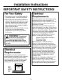
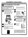
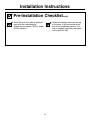
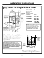
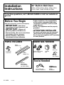
Installation
Instructions
30” Built-In Wall Oven
JTP20, JTP25, JTP28, JTP48, JTP50, JT912,
JT915, JT952, JT955, ZET938, ZET958
If you have questions, call 1.800.GE.CARES or visit our website at:
ge.com
Before You Begin
• Proper installation is the responsibility
of the installer and product failure due
to improper installation is NOT covered
under warranty.
• NOTE—This appliance must be properly
grounded.
Read these instructions carefully and completely.
•
IMPORTANT—Save these
instructions for local inspector’s use.
•
IMPORTANT—Observe all
•
governing codes and ordinances.
• Note to Installer—Be sure to leave these
instructions with the consumer.
• Note to Consumer—Keep these
instructions for future reference.
ATTENTION INSTALLER
All electric wall ovens must be hard wired
(direct wired) into an approved junction
box. A plug and receptacle is NOT permitted
on these products.
Materials Needed
Parts Included
Metal
Bottom Trim
Wire Nuts
Screws For
Installation
Strain Relief Clamp
for 1/2” conduit
Plastic
Bottom Trim
Junction
Box
36” of String
Tools Needed
Optional
Metal Bottom
Trim Assembly
(on some models)
1/8” Drill Bit and
Electric or Hand Drill
31-10659
1-07 JR
1
Phillips
Screwdriver
Installation Instructions
IMPORTANT SAFETY INSTRUCTIONS
For Your Safety
Electrical
Requirements
• Be sure your oven is installed properly by
a qualified installer or service technician.
• Be sure the oven is securely installed in a
cabinet that is firmly attached to the house
structure. Weight on the oven door could
cause the oven to tip and result in injury.
Never allow anyone to climb, sit, stand or
hang on the oven door.
• Make sure the cabinets and wall coverings
around the oven can withstand the
temperatures (up to 200°F) generated
by the oven.
We recommend you have the electrical wiring
and hookup of your oven connected by a
qualified electrician. After installation, have the
electrician show you where your main oven
disconnect is located.
Check with your local utilities for electrical
codes which apply in your area. Failure to wire
your oven according to governing codes could
result in a hazardous condition. If there are no
local codes, your oven must be wired and fused
to meet the requirements of the National
Electrical Code, ANSI/NFPA No. 70–Latest
Edition. You can get a copy by writing:
National Fire Protection Association
Batterymarch Park
Quincy, MA 02269
Effective January 1, 1996, the National
Electrical Code requires that new, but not
existing, construction utilize a four-conductor
connection to an electric oven. When installing
an electric oven in new construction, a mobile
home, recreational vehicle or an area where
local codes prohibit grounding through the
neutral conductor, follow the instructions in
the section on NEW CONSTRUCTION AND
FOUR-CONDUCTOR BRANCH CIRCUIT
CONNECTION.
You must use a three-wire, single-phase A.C.
208Y/120 Volt or 240/120 Volt, 60 hertz
electrical system. If you connect to aluminum
wiring, properly installed connectors approved
for use with aluminum wiring must be used.
WARNING: The electrical
power to the oven supply line
must be shut off while line
connections are being made. Failure
to do so could result in serious injury
or death.
Electrical
Requirements
This appliance must be supplied with the
proper voltage and frequency, and connected
to an individual, properly grounded branch
circuit, protected by a circuit breaker or fuse
having amperage as noted on rating plate.
(Rating plate is located on oven frame.)
Rating
Plate
Location
(behind
oven
door)
2
Installation Instructions
Pre-Installation Checklist
ALL INSTALLATION INFORMATION
ON THE FOLLOWING PAGES IS TO
BE USED FOR SINGLE AND DOUBLE
OVEN INSTALLATION!
Door removal is not a requirement for
installation of the product, but is an
added convenience. To remove the door:
Open the oven door as far as it will go.
Remove packaging materials.
Check behind hinges and under
false bottom. Remove labels on the
outside of the door, plastic on trims
and panel, all tape around the oven,
and any shipping screws securing
the oven to the base pad.
Push both hinge
locks down toward Hinge
the door frame,
Hinge
Slot
Slot
to the unlocked
position. This may
require a flat blade
screwdriver.
Hinge
Hinge
Unlocked
Unlocked
Position
Position
Hinge
Hinge
Arm
Arm
DO NOT LIFT THE DOOR
BY THE HANDLE!
Place hands on both sides of
the door, and close the oven
door to the removal position.
This is half way between the
broil stop and fully closed.
Oven Racks
EASY
INSTA
LLA
TIO
EASY
INSTALLATION
OFNYOUR NEW
Before
30"
IMPOR you begin
WALL OF YO
30"
-Read WALL OVEN
IMPOR TANTOVEN UR NE
Save
these
Note TANTinstru
OBSE these
W
to
Broiler Pan
and Grid
instru
Install
ctions
OWNE
RVE instructions
you begin-Read
completely and carefully.
Before
er- Bethese
comp
ALL ctions
Note- R- Keep
for inspector’s
GOVE
these sure
instructions
for local
IMPORTANTletelyuse.
ThisSave these
to leave RNINGlocal inspec and
applia
IMPORTANT- OBSERVE
ALL
GOVERNING
CODES AND ORDIANCES.
instru
carefu
CODE
these
nce
tor’s
ctions
Note to Installer- Be suremust
to leave
these
with
the consumer.
S AND
instru
use. lly.
for instructions
be
ctions
future
ORDIA
OWNER- Keep these instructionsprope
for future
reference.
with
rly grounrefere
FOR
the NCES.
Note- This
appliance must be properly grounded
(if applicable).
nce.
YOUR
consu
ded
SAFE
(if applic
mer.
Before
TY
able).
instru you begin
carefu ctions comp-Read
lly. YOUR SAFETY
ELECTRICAL REQUIREMENTS
IMPORFOR
letely these
and
ELEC
instru TANTTRICA
ctionsyouSave
Before
begin-Read
IMPOR
Before you begin-Read
these these
L REQU these
Before
TANT for local
completely and
GOVEinstructions
IREME
instructions completely
and
RNING - OBSE inspec
instru you begin
NTS
Note carefully.
tor’s
carefully.
RVE
to Install CODE Save
carefu ctions comp-Read
use.
ALL
these
these IMPORTANTIMPORTANT- Save these
er- Be S AND
IMPOR lly.
letely these
instructions
localORDIA
inspector’s use.
OWNE instru
instructions for localand
inspector’s use.
sure
ctions for
instru TANTNCES
Rto leave
IMPORTANTOBSERVE
ALL
for future
Keep
with
Save OBSERVE ALL
IMPORTANTctions
.
the
these CODES
these
NoteGOVERNING
AND ORDIANCES. IMPORGOVERNING
for localCODES
refere
AND ORDIANCES.
instru consu
GOVE TANTctions
prope ThisNote
inspec
tonce.
Installer- Be
sure mer.
to leave
applia
OBSE
RNING
Note
to
InstallerBe sure to leave
rly groun nce
Note
tor’s
RVE
these instructions
with the consumer.
Before
to these CODE
instructionsALL
with theuse.
consumer.
ded must be
these Install
S AND
instru youOWNERKeep
these instructions
er- Be
begin (if
applic
OWNERKeep
these instructions
OWNE instru
ctions sure ORDIANCES
-Read
able).
carefu ctionsfor
future
reference.
R- Keep
to leave
for futurewith
reference.
comp
for future
these
.
IMPOR lly. Note- This
letelyappliance
must be
the
Note-these
This appliance
must be
Noterefere
and
instru consumer.
instru TANT-properly grounded
(if
applicable).
This
nce.
properly grounded
(if applicable).
Save
ctions
prope
applia
IMPORctions for
Beforethese
you begin-Read these
nceyou begin-Read these
Before
Beforerly groun
local
GOVE TANT- instructions
ded mustcompletely
OBSE inspeccompletely and
instructions
and
instru you begin
(if applicbe
Note RNING carefully.
CODE RVE ALL tor’s use.
-Read
carefully.
to
carefu ctions comp
able).
these Install
S AND
Save these
er-IMPORTANTIMPOR lly.
letely these
IMPORTANTSave these
OWNE instructionsBe sure ORDIA
and
instructions
for local
inspector’sinstru
use. TANT instructions for local inspector’s use.
NCES
R- Keep
to leave
for future
with
. ALL IMPORctions - Save
IMPORTANTOBSERVE
the
these
IMPORTANTOBSERVE ALL
these
for local
Noterefere
instru consu
GOVERNING
CODES AND ORDIANCES.
GOVE TANTGOVERNING
inspec CODES AND ORDIANCES.
ctions mer.
prope This appliance.
OBSE
Note RNING
rly groun nceNote to Installer- Be sure to leave
tor’s Be sure to leave
RVE
Note
to InstallerCODE
to
use.
ALL
mustinstructions with the consumer.
these Install
ded these
S AND
instructions with the consumer.
er- these
(if applicbe
OWNE instructionsBeOWNEROWNER- Keep these instructions
sure ORDIA
Keep these instructions
able).
R- Keep
to leave NCES
for future
with
for future reference.
reference. .
the
thesefor future
Noteconsu
refere
Note- This appliance must be
instruThis
Noteappliance must be
ctions mer.
prope This appliance.
properly grounded (if applicable).
rly groun nce properly grounded (if applicable).
must
ded
(if applicbe
able).
Literature
Pack
Lift door up and
out until the
hinge arms
clear the slots.
Open oven door and remove literature
pack, broiler pan and grid, and oven
racks.
Remove Installation Instructions from
literature pack and read them carefully
before you begin.
Be sure to place all literature, Owner’s
Manual, Installations, etc. in a safe place
for future reference.
Hinge Clears Slot
NOTE: The oven door is very heavy. Be sure
you have a firm grip before lifting the oven
door off the hinges. Use caution once the
door is removed. Do not lay the door on its
handle. This could cause dents or scratches.
3
(Continued on following page)
Installation Instructions
Pre-Installation Checklist cont.
Place the oven on a table or platform
even with the cutout opening.
(Platform must support 150 lbs. single,
275 lbs. double.)
Remove the bottom trim from the top
of the oven. It will be installed at the
end of the installation process. The
trim is wrapped separately and taped
to the top of the unit.
4
Installation Instructions
A1
Cutout for Single Built-In Oven
Cutout
CUTOUT
Width
WIDTH
28
Min.
28 1/2”
1/2" MIN.
28
5/8”MAX.
Max.
28 5/8"
5”
5"
JUNCTION
BOX
Junction Box
LOCATION
Location
ALLOW 11/16" FOR
OVERLAP OF THE
Allow 11/16” for
OVEN OVER SIDE
overlap of oven
EDGES OF CUTOUT
over side edges
of cutout
Opening
Between
THE
OPENING
Inside INSIDE
Walls
BETWEEN
WALLS
MUST
Must Be
BE
LEAST
AtAT
Least
28 1/2"WIDE
28 1/2” Wide
Cutout
CUTOUT
Height
HEIGHT
27
1/4”MIN.
Min.
27 1/4"
27
5/16"
27 5/16”MAX.
Max.
22"
22”TO
to
BOTTOM
Bottom OF
of
JUNCTION BOX
Cabinet Width
30”
Recommended
Minimum
Cutout Location
from Floor
32 1/2”
Cutout Depth
23 1/2” Min.
Cutout Width
28 1/2” Min.
28 5/8” Max.
Cutout Height
27 1/4” Min.
27 5/16” Max.
Junction Box
21”
21"
ALLOW
AllowAaMINIMUM
minimum of
OF 21" FOR CLEARANCE
21” for clearance
TO ADJACENT
CORNERS,to
adjacent
corners,
DRAWERS,
WALLS
ETC.
WHEN THE
DOORwalls,
IS OPENED.
drawers,
etc.
when door is open
Allow
1”
ALLOW
1" FOR
OVERLAP for
minimum
ON OVENofTOP
overlap
oven
AND BOTTOM
top
and 11⁄4”
OF CUTOUT
RECOMMENDED
Recommended
CUTOUT
minimum
cutout
LOCATION
32 1/2"
location
from
FROM
THE
floor
32 1/2”
FLOOR
NOTE: If the cabinet does not
have a front frame and the
sides are less than 3/4” thick,
shim both sides equally to
establish the cutout width.
overlap of oven
bottom of cutout
CABINET
Cabinet
WIDTH
Width
30"
30”
If the cabinet does not have a solid bottom,
two braces or runners must be installed
level with the bottom of the cutout to
support the weight of the oven. For single
ovens, the runners and braces must
support 150 lbs.
CL
2”x x4"4”
2"
or or
EQUIVALENT
equivalent
RUNNERS
runners
level with
bottom
of cutout
NOTE: If marks, blemishes or the
cutout opening are visible above the
installed oven, it may be necessary to
add wood shims under the runners and
front trim until the marks or opening
are covered.
Suitable
Bracing
to Support
SUITABLE
Runners
BRACING
TO SUPPORT
RUNNERS
21
5/8”
21 5/8"
OVER CENTERLINE
Over
Centerline
OF CABINET
of Cabinet
This oven is not approved for
stackable or side by side installation.
5
Installation Instructions
A2
Cutout for Double Built-In Oven
Cutout
CUTOUT
Width
WIDTH
28
Min.
28 1/2”
1/2" MIN.
28
Max.
28 5/8”
5/8" MAX.
Junction
JUNCTIONBox
BOX
LOCATION
Location
ALLOW 11/16"
FOR OVERLAP
Allow
for
OF11/16”
THE OVEN
overlap
of oven
OVER SIDE
EDGES
over OF
side
edges
CUTOUT
of cutout
ALLOW A MINIMUM OF 21"
Allow
a minimumTO
of
FOR CLEARANCE
21” for clearance
to
ADJACENT
CORNERS,
adjacent corners,
DRAWERS,
WALLS ETC.
drawers,
walls,
etc.
WHEN THE
DOOR
whenISdoor
is open
OPENED.
Opening
Between
THE OPENING
Inside
Walls
BETWEEN
Must Be INSIDE
WALLS MUST
At
BELeast
AT LEAST
28281/2”
Wide
1/2"WIDE
Allow 1”
minimum for
overlap of oven
ALLOW
1"1FOR
1
top
and
⁄”
OVERLAP4
overlap
of
ON OVEN TOP
ovenBOTTOM
bottom
AND
OF
of CUTOUT
cutout
Cabinet Width
30”
Recommended
Minimum
Cutout Location
from Floor
12”
Cutout Depth
23 1/2” Min.
Cutout Width
28 1/2” Min.
28 5/8” Max.
Cutout Height
51 13/16” Min.
51 15/16” Max.
5”
5"
47”TO
to
47"
BottomOF
of
BOTTOM
JUNCTION
Junction BOX
Box
Cutout
CUTOUT
Height
HEIGHT
51 13/16”
13/16" MIN.
51
Min.
51
15/16"
51 15/16”MAX.
Max.
NOTE: If the cabinet does not
have a front frame and the
sides are less than 3/4” thick,
shim both sides equally to
establish the cutout width.
21”
21"
30"
30”
Cabinet
CABINET
WIDTH
Width
Recommended
RECOMMENDED
CUTOUT LOCATION
minimum
cutout location
12"
FROM
from
floorTHE
12”FLOOR
f the cabinet does not have a solid bottom,
two braces or runners must be installed
level with the bottom of the cutout to
support the weight of the oven. For double
ovens, the runners and braces must
support 275 lbs.
CL
2”x x4"4”
2"
or or
EQUIVALENT
equivalent
RUNNERS
runners
level with
bottom
of cutout
NOTE: If marks, blemishes or the
cutout opening are visible above the
installed oven, it may be necessary to
add wood shims under the runners and
front trim until the marks or opening
are covered.
Suitable
Bracing
to Support
SUITABLE
Runners
BRACING
TO SUPPORT
RUNNERS
21
5/8”
21 5/8"
OVER
OverCENTERLINE
Centerline
OF CABINET
of Cabinet
6
Installation Instructions
A3
Cutout for Single Built-In Oven
Under Counter
Gas or electric cooktops
mayGas
be or
installed
over thismay
electric cooktops
be See
installed
over this
oven.
oven.
cooktop
installation
See cooktop
instructions
forinstallation
cutout size.
instructions for cutout size.
See See
label
on top of oven for
label on top of oven for
approved
cooktop
approved
cooktopmodels.
models.
Gas and electrical connections
forGas
30"and
gaselectrical
cooktop
must be for
connections
located
incooktop
an adjacent
accessible
30” gas
must be
located
in an adjacent
accessible
location
to the right.
For location
a 36"
the right. For 36” gas cooktop,
gastocooktop
the connections
the connections may be made
may
to the left.
to be
the made
left.
240V / 208V
240V / 208V
Junction
Box
Junction Box
Location
Location
25”
25"
5”
5"
Topand/or
and/or
side
Top
side
fillers
fillers
be
may
be may
necessary
necessary
if
if
unit is positioned
unit is positioned
between
existing
betweenBe
existing
cabinets.
sure
cabinets.
Be sure
they
are attached
securely,
they
they aresince
attached
will
anchorsince
the oven
securely
in
the will
cabinet.
they
anchor
28 1/2”
1/2"Min.
MIN.
28 5/8”
5/8"Max.
MAX.
Allow
11/16"
Allow 1”
overlap
top of oven
and
Overlap
Top
11/16”
overlap
of
Oven
&
side edges
of
Side
Edges
cutout
of
Cutout
271/4"
1/4” Min.
27
MIN.
275/16"
5/16” Max.
27
MAX.
the oven in the
cabinet.
22"
MIN.
22” Min.
Above
Above
Support
Support
Platform
Platform
36"
36”
Typical
Typical
Countertop
Countertop
Height
Height
24"
24”
3/4" Support
3/4”
Platform
Support
Platform
Required
Required
9/16”
55Reference
9/16"
dimension for
Reference
dimension
maximum support
height with
for
maximum
support
height
typical 36” countertop
height
with typical 36" countertop
height
MUST
150LBS.
LBS.
MUST SUPPORT
SUPPORT 150
NOTE: This oven is not approved to be
installed under a solid disk, induction
or downdraft modular cooktop.
7
Installation Instructions
B
Electrical Connections
ATTENTION INSTALLER
All electric wall ovens must be hard wired
(direct wired) into an approved junction
box. A plug and receptacle is NOT permitted
on these products.
DO NOT shorten the flexible conduit.
The conduit strain relief clamp must be
securely attached to the junction box
and the flexible conduit must be securely
attached to the clamp. If the flexible
conduit will not fit within the clamp, do not
install the oven until a clamp of the proper
size is obtained.
B1
Turn off the circuit breaker or remove
fuses to the oven branch circuit.
B2
With the oven supported on a table or
platform in front of the cabinet opening,
connect the flexible conduit to the
electrical junction box as shown below.
Position the conduit in such a manner
that it will lie on top of the oven in
a natural loop when the oven is
installed. You will need to purchase
an appropriate strain relief clamp to
complete the connection of the conduit
to the junction box.
Junction Box
Location
NOTE TO ELECTRICIAN: The 3 power
leads supplied with this appliance are
UL recognized for connection to heavier
gauge household wiring. The insulation
of these 3 leads is rated at temperatures
much higher than the temperature rating
of household wiring. The current carrying
capacity of the conductor is governed
by the wire gauge and the temperature
rating of the insulation around the wire.
5”
Conduit
48 1/2”
long
GROUND
WIRE
BARE
GROUND
RED
WHITE
BLACK
WARNING: Improper
Place oven on a
support to assist in
connecting conduit
connection of aluminum house
wiring to copper leads can
result in an electrical hazard or fire.
Use only connectors designed for
joining copper to aluminum and follow
the manufacturer’s recommended
procedure closely.
8
Strain Relief Clamp
(not included)
must be used at
Junction Box
(Continued on following page)
Installation Instructions
B
Electrical Connections cont.
B3 New Construction and
Four-Conductor Branch
Circuit Connection
B4 Three-Conductor Branch
Circuit Connection
When connecting to a three-conductor branch
circuit, if local codes permit:
• When installing in new construction, or
a. Connect the bare oven ground conductor
with the crimped neutral (white) lead to
the branch circuit neutral (white or gray
in color), using a wire nut.
• When installing in a mobile home, or
• When installing in a recreational vehicle, or
• When local codes do not permit grounding
through neutral:
a. Cut the neutral (white) lead from the crimp.
Re-strip the neutral (white) lead to expose
the proper length of conductor.
Ground and
Neutral Wires
Ground
Wire
Junction Box
Cover
b. Connect the oven red lead to the branch
circuit red lead in accordance with local
codes, using a wire nut.
Junction Box
Cover
c. Connect the oven black lead to the branch
circuit black lead in accordance with local
codes, using a wire nut. If the residence
red, black or white leads are aluminum
conductors, see WARNING on page 8.
b. Attach the appliance grounding lead (green
or bare copper) in accordance with local
codes. If the residence grounding conductor
is aluminum, see WARNING on page 8.
d. Install Junction Box Cover.
c. Connect the oven neutral (white) lead to
the branch circuit neutral (white or gray)
in accordance with local codes, using a
wire nut.
d. Connect the oven red lead to the branch
circuit red lead and the oven black lead to
the branch circuit black lead in accordance
with local codes, using wire nuts. If the
residence red, black or white leads are
aluminum conductors, see WARNING on
page 8.
e. Install Junction Box Cover.
9
Installation Instructions
C
Securing the Oven in the Opening
C1 Sliding the Oven Into the
Opening
C2 Drilling the Pilot Holes and
Mounting the Oven
a. Loop (do not tie) a 36” string around the
conduit before the oven is slid into place.
This will keep the conduit from falling
behind the oven.
NOTE: Before drilling the pilot holes,
make sure the oven is pushed as far
back into the opening as it will go
and centered.
a. Drill through the mounting holes (top and
bottom) of the side trim, for the #8 screws
provided.
Pull out on
string loop
while pushing
the oven into
the cabinet
Mounting
Hole
Locations
The screws must
be a minimum of
1/4” from the front
of the cutout.
b. Lift oven into cabinet cutout using the oven
opening as a grip. Carefully push against
oven front frame. Do not push against
outside edges.
c. As you slide the oven back, pull the string
so that the conduit will lie on top of the
oven in a natural loop.
WARNING: Mounting
screws must be used. Failure to
do so could result in the oven
falling out of the cabinet causing
serious injury.
d. When you are sure the conduit is out of the
way, slide the oven 3/4 way back into the
opening. Remove the string by pulling on
one end of the loop.
b. Secure the oven to cabinet with screws
provided.
NOTE: If the cabinet is particle board, you
must use #8 x 3/4” particle board screws.
These may be purchased at any hardware
store.
10
(Continued on following page)
Installation Instructions
To install a single metal bottom trim assembly (on some models), use sections C3 and C4.
To install a metal bottom trim with a plastic bottom trim (on some models), use sections C3–C5.
C3 Preparing for the Bottom
Trim Installation
C5 Installing the Plastic Bottom
Trim (on some models)
a. With oven installed, take the bottom trim
and center it on the bottom front edge of
the cabinet opening.
a. Make sure flat side is up on the plastic
bottom trim.
b. Using the trim
as a template,
mark the center
of each slot
(two total) where
the mounting holes
will be drilled.
b. Find the key slot on the back of the trim.
With Lower Trim
in Position, Mark
(2) Mounting Hole
Locations
Key Hole Slot and Wide Flange at Top
Remove
Lower Trim
Before
Pre-drilling
Mounting
Holes
c. Remove the trim.
d. Drill pilot holes into the center
of each template mark.
c. Match the key slot with the rivet on the
bottom of the side trim, and lower the trim
onto the rivet.
C4 Installing the Metal
Bottom Trim
a. Place the bottom metal trim centered over
the pre-drilled mounting holes. Tape the
edges of the trim down to maintain the
alignment.
Lower Trim Mounting Rivet
on End of Metal Lower Trim
d. Push the trim down, at both ends, until it
snaps securely into place.
b. Using two trim screws provided, secure
the bottom trim to the bottom edge of the
cabinet. If a plastic bottom trim is supplied,
proceed to C5.
Side
Trim
Trim Screws
Push Trim Down at Both Ends
Until it Snaps Securely Into Place
Side
Trim
CAUTION: Be sure you
Metal Lower Trim
do not tip the oven forward
during installation or you may
bend the bottom trim. The bottom trim
provides an opening for cooling air to
enter the cabinet. This opening should
never be blocked.
IMPORTANT: If this unit is ever
removed from the cabinet or the oven
is ever pulled out for service, the trim
must be removed first or damage to
the trim will occur.
11
Installation Instructions
D
Replacing the Oven Door
NOTE: The oven door is heavy. You
may need help lifting the door high
enough to slide it into the hinge slots.
Do not lift the door by the handle.
D1
D3
Open the oven door as far as it
will open.
D4
Push the hinge locks up against the
front frame of the oven cavity, to the
locked position.
Hinge in
Locked Position
Lift the oven door by
placing one hand on
each side. The door is
heavy, so you may need
help. Do not lift the door
by the handle.
Notch of Hinge
Securely Fitted
into Bottom of
Hinge Slot
D5
D2
With the door at the same angle as
the removal position (half way between
the closed and broil stop position,
seat the notch of the hinge arm into
the bottom edge of the hinge slot.
The notch of the hinge arm must be
fully seated into the bottom of the slot.
Hinge Arm
Bottom Edge
of Slot
Hinge Notch
12
Close the oven door.
Installation Instructions
Pre-Test Checklist
Remove all protective film, if present,
and any stickers.
Check that the bottom trim is installed
properly (see page 11).
Check to be sure that all wiring is
secure and not pinched or in contact
with moving parts.
Check to be sure the mounting screws
are installed and flush with the side trim
(see page 10).
Operation Checklist
Remove all items from the inside
of the oven.
NOTE TO ELECTRICIAN: The power
leads supplied with this appliance
are UL recognized for connections
to larger gauge household wiring.
The insulation of these leads is
rated at temperatures much higher
than the temperature rating of
household wiring. The current
carrying capacity of a conductor
is governed by the wire gauge and
also the temperature rating of the
insulation around the wire.
Check that conduit is securely
connected to the junction box.
Turn on the power to the oven. (Refer
to your Owner’s Manual.) Verify that
the bake and broil units, and all
cooking functions operate properly.
Check that the circuit breaker is not
tripped nor the house fuse blown.
NOTE: ALUMINUM WIRING
See your Owner’s Manual for
troubleshooting list.
A.
WARNING: IMPROPER
CONNECTION OF ALUMINUM
HOUSE WIRING TO THE COPPER
LEADS CAN RESULT IN AN
ELECTRICAL HAZARD OR FIRE.
B. Splice copper wires to aluminum
wiring using special connectors
designed and UL approved for
joining copper to aluminum,
and follow the manufacturer’s
recommended connector
procedure closely.
NOTE: Wire used, location and
enclosure of splices, etc., must
conform to good wiring practice
and local codes.
13
NOTES
14
NOTES
15
NOTES
16