1
Operator’s Manual
GASOLINE POWERED EARTH AUGER
43cc, 2-CYCLE
MODEL No. SEA438
Look inside for:
Safety Definitions
Important Safety Information
Product Specifications
Parts & Features
Assembly
Operation
Routine Maintenance
Troubleshooting
Technical Service
Warranty
SEA43
Page
1
2-4
5
5
5-6
6-8
9-10
11
11
12-17
IMPORTANT:
Thank you for purchasing this Southland® Earth Auger.
This manual provides complete instructions for safely operating, and maintaining your Earth Auger. Read and save these
instructions. Refer to this manual each time before using your Earth Auger.
Record the following for future reference:
Mfg. Date Code : __________________
Date of Purchase: Attach a copy of your sales receipt.
Consumer Toll Free Number: 1-800-737-2112
Refer to the website for electronic manual and parts book.
www.southlandpowerequipment.com
WARNING CALIFORNIA PROPOSITION 65 WARNING
Engine exhaust, some of its constituents, and certain product components contain or emit chemicals known to the State
of California to cause cancer and birth defects or other reproductive harm.
If you have a question or problem...
CALL TOLL FREE: 1-800-737-2112
KEEP THIS MANUAL FOR FUTURE REFERENCE
09/14/2010
Printed in China
A200128
Safety Definitions
• Save all instructions
Safety Warning Symbols:
Extremely hot surface. Do not touch
a hot muffler, gear box or cylinder,
you may get burned. These parts get
extremely hot from operation and
remain hot for a short time after the unit
is turned off.
Indicates Warning.
Read these instructions carefully.
Control and Operating Symbols:
Choke Control:
Cold Start
Fuel Mixture:
Fuel Mixture
40:1
Run/Warm Start
Unleaded Gas: 2 Cycle Oil
Caution: Do Not Use Gas
Mix with More Than 10%
Ethanol
Fuel Primer:
Press 6 times.
ON
OFF
40:1
(Unleaded Gas : 2 Cycle Oil)
Ignition Switch:
ON
OFF
The information listed below should be read and understood by the operator. We utilize the symbols below to allow the
reader to recognize important information about their safety.
DANGER
WARNING
CAUTION
Indicates an imminently hazardous situation which, if not avoided, will result in death or serious injury.
Indicates a potentially hazardous situation which, if not avoided, could result in death or serious injury.
Indicates a potentially hazardous situation which, if not avoided, may result in minor or moderate injury
or equipment/property damage.
Questions? Call Toll Free at 1-800-737-2112
1
Copyright © 2010 MAT Engine Technologies, LLC
Important Safety Information
• Save all instructions
READ AND UNDERSTAND ALL INSTRUCTIONS BEFORE OPERATING Earth Auger.
Before Operating Earth Auger
DANGER
1. Contact your local utility company in order to locate underground electrical lines or pipes prior to using this product.
Failure to do so may result in serious injury or death and possible damage to equipment or property.
2. The auger engine exhaust contains carbon monoxide, an orderless and potentially deadly gas. Never start or run the
auger inside an enclosed area or building. Breathing exhaust fumes can kill.
WARNING
Read and follow all warnings and safety instructions. Failure to do so can result in serious injury to you or bystanders.
1. Avoid Dangerous Environments
a. Do not operate Earth Auger while under the influence of alcohol, medications, or drugs.
b. Do not operate Earth Auger when you are tired.
c. Do not use this Earth Auger if you are mentally or physically unable to operate safely.
2. Inspect Earth Auger for damaged parts, and make sure all fasteners and guards are in place and secure. Replace any
damaged parts.
3. The handles must be mounted in accordance with the Operators Manual.
4. Never use this Earth Auger with other accessories not specifically designed for use with this product.
5. Dress properly when operating Earth Auger.
a. Always wear heavy long pants, boots, gloves, and a long-sleeve shirt.
b. Do not wear loose clothing or jewelry that can get caught in the moving parts of the Earth Auger.
c. Always wear protective hair covering to contain long hair.
6. Always wear a face or dust mask if operation is dusty.
7. Always wear eye protection that meets or exceeds the requirements of ANSI Z87.1.
8. Always wear hearing protection, which meets or exceeds ANSI standards.
9. Thoroughly inspect the area where the Earth Auger is to be used and remove all foreign objects.
10.Auger blades and drilling points are sharp. Avoid contact with the auger blades and drilling points while installing auger
bit, starting or transporting the unit.
While Operating Earth Auger
CAUTION
Prolonged exposure to vibrations through use of gasoline powered hand tools could cause blood vessel or nerve damage
in fingers, hands, and joints of people prone to circulation disorders or abnormal swellings. Extensive use in cold weather
has been linked to blood vessel damage in otherwise healthy people. If symptoms occur such as numbness, pain, loss of
strength, change in skin color or texture, or loss of feeling in the fingers, hands, or joints, discontinue the use of this tool
and seek medical attention.
WARNING
1. Maintain a firm grip on the handles with both hands while using the auger. Keep the auger bit away from your body and
below waist level.
2. Stay alert. Use common sense. Watch what you are doing.
3. Do not operate Earth Auger if it is damaged or not securely and fully assembled.
4. Only well instructed adults should operate Earth Auger. Never allow children to operate Earth Auger.
Questions? Call Toll Free at 1-800-737-2112
2
Copyright © 2010 MAT Engine Technologies, LLC
Important Safety Information
(Continued)
• Save all instructions
While Operating Earth Auger
5. Keep children away. Keep all bystanders at least 50 ft (15 m) away.
6. This Auger is only intended for earth digging. Do not use Earth Auger for any job except that for which it is intended.
Severe personal injury to yourself or others can result.
7. The Auger Bit should not rotate while engine is idling. If it does rotate when engine is idling, contact technical service
immediately for instructions.
8. Maintain your balance and proper footing at all times. Do not overreach.
9. Keep all parts of your body away from cutting area, the rotating auger bit and blades, and hot surfaces.
10.Always keep the throttle control on your right hand side, while the exhaust points away from your body.
11.Use extreme caution when using this unit. Bit thrust or Kick Back may occur when the spinning blade contacts an object
that it does not immediately cut. A Kick Back can be violent enough to cause the unit and/or operator to be propelled
in any direction, and possibly lose control of the unit. Kick Back can occur without warning if the bit snags, stalls or
binds.
12. An improper or dull bit blade can cause serious personal injury. Bit blades must be sharp. Discard earth bit blades that
are bent, warped, cracked, broken or damaged in any way.
13.Use only the manufacturer’s replacement bit blade intended for this unit. Do not use any other bit blade. To install any
other brand bit blade to this unit can result in serious personal injury.
14.Do not force the earth auger. It will do the job better and with less likelihood of a risk of injury when used at the rate
for which it was designed.
15.After turning the unit off, make sure the earth auger bit has stopped before the unit is sat down.
16.A coasting bit can cause injury while it continues to spin after the engine is stopped or throttle lever is released.
Maintain proper control until the bit has completely stopped rotating.
17.Never touch the area near the muffler because it is extremely hot and can cause severe burns. Never touch parts of
the engine that become hot after operation.
Fuel Safety
WARNING
1. Mix and pour fuel outdoors WHERE THERE ARE NO SPARKS OR FLAMES.
2. Never fill gasoline container or the product’s fuel tank inside a vechile or in a truck bed. Accidental electrical static
discharge can ignite fuel vapors which could result in serious injury or death.
3. Use a container approved for gasoline.
4. Do not smoke or allow smoking near fuel or the unit.
5. Avoid spilling fuel or oil. Wipe up all fuel spills.
6. Move at least 10 feet (3 meters) away from fueling site before starting engine.
7. Stop engine and allow to cool before removing fuel cap. Remove fuel cap slowly.
8. Store unit and fuel in area where fuel vapors cannot reach sparks or open flames from water heaters, electric motors
or switches, furnaces, ect..
Questions? Call Toll Free at 1-800-737-2112
3
Copyright © 2010 MAT Engine Technologies, LLC
Important Safety Information
(Continued)
• Save all instructions
Maintenance, Transporting & Storage of Earth Auger
1. Disconnect the spark plug before performing maintenance. Secure spark plug boot away from engine and frame to
prevent arcing.
2. Maintain Earth Auger with care. Inspect unit periodically. If unit is not working properly or damaged, have it repaired by
a qualified service center.
3. Check for misalignment of moving parts, binding of moving parts, broken parts, mounting, and any other condition that
may affect its operation.
4. Any part that is damaged should be properly repaired or replaced by a qualified service center.
5. Use only genuine Southland® replacement parts and accessories. Use of any non-Southland® parts or accessories
could lead to injury, damage to the unit, and will void your warranty.
6. Do not remove or modify any parts. Removing or modifying parts could lead to injury, damage the Earth Auger and will
void the warranty.
7. Keep handles dry, clean, and free from oil and grease.
8. Allow engine to cool and empty the fuel tank into an approved container before storing or transporting in vehicle. Use
up remaining fuel in the carburetor by starting the engine and letting it run until it stops.
9. When not in use, store unit indoors in a dry location. Store Earth Auger above the reach of children or in a locked area
out of the reach of children.
10. For cold weather operation, store the unit in a cool environment to minimize the possibility of condensation which could
lead to unsatisfactory product performance.
11. When preparing the Earth Auger for storage or when Earth Auger will not be used for 30 days or more:
a. Inspect and clean the Earth Auger thoroughly.
b. Lightly oil all external metal surfaces.
c. Remove the spark plug, place a few drops of 2-cycle engine oil into the cylinder. Pull the recoil starter
several times to distribute the oil. Replace the spark plug.
d. Inspect and clean air filter as required.
NOTE: To prevent fuel gum deposits in the carburetor and fuel system, it is acceptable to use fuel stabilizer. Follow the stabilizer
manufacturer’s instructions. Run the engine at least 5 minutes after adding stabilizer.
WARNING
Store unit and fuel in area where fuel vapors cannot reach sparks or open flames from water heaters, electric motors or
switches, furnaces, etc.
Questions? Call Toll Free at 1-800-737-2112
4
Copyright © 2010 MAT Engine Technologies, LLC
Product Specifications
• Save all instructions
Engine . . . . . . . . . . . . . . . . . . . . . . . . . . . . . . . 43cc, 2 cycle Spark Plug . . . . . . . . . . . . . . . . . . . . . . . . . . NGK - BPMR7A
Fuel Tank Capacity . . . . . . . . . . . . . . . . . . . 40.6 oz (1.2 L) . . . . . . . . . . . . . . . . . . . . . . . . . . . . . . . CHAMPION - CJ7Y
Fuel Type . . . . . . . . Unleaded Gasoline – 87 Octane or higher . . . . . . . . . . . . . . . . . . . . . . . . . . . . . . . . . . TORCH L7RTC
Auger Bit . . . . . . . . . . . . . . . . . 8˝ (included for Model PEA438) . . . . . . . . . . . . . . . . . . . . . . . . . . . . . . . . . . . . . or equivalent
2-Cycle Oil Type . . . . . . . 2-Cycle Oil that meets or exceeds Net Weight . . . . . . . . . . . . . 43cc Auger Powerhead - 22 lbs
. . . . . . . . . . . . . . . . . . . . . . . . . . . JASO – FC Specifications . . . . . . . . . . . . . . . . . . . . . . . . . . . . . . . 8˝ Auger Bit - 13 lbs
Fuel Mixture . . . . . . . . . . . . . . . . 40:1 (Gasoline: 2-Cycle Oil)
6˝ Auger Bit - 12 lbs
Parts & Features
10
2
11
7
6
11
3
5
9
1
4
8
12
13
14
13 14
Powerhead:
8˝ Auger Bit:
1.
On/Off Ignition Switch
6.
Muffler
11.
Adapter
2.
Recoil Starter Handle
7.
Fuel Tank
12.
6˝/8˝ Auger Body
3.
Choke Lever
8.
Air Filter Cover
13.
Earth Blade (replaceable)
4.
Fuel Primer Bulb
9.
Gear Box
14.
Fishtail Point (replaceable)
5.
Spark Plug
10.
Throttle Lever
Assembly
If you need assistance or find any parts
missing, CALL TOLL FREE: 1-800–737-2112
Parts Included With The Earth Auger
1.
2.
3.
4.
43cc Auger Powerhead
8˝ Auger Bit (Included for Model PEA438)
Fishtail Point
M8-1.25 x 45 Bolt & Locknut
5.
6.
7.
8.
13mm x 10mm Wrench
13mm x 12mm Wrench
Spark Plug Wrench
2-Cycle Engine Oil Bottle
WARNING
Do not operate Earth Auger if it is damaged or not securely and fully assembled.
Tools Needed For Assembly
• Adjustable wrench.
Questions? Call Toll Free at 1-800-737-2112
5
Copyright © 2010 MAT Engine Technologies, LLC
Assembly
(Continued)
• Save all instructions
A
To Assemble Auger Bit
1. Insert the spark plug wrench handle into the cross hole in the adapter.
2. Hand tighten the Fishtail Point into the opposite end of the adapter. Avoid contact with the Earth Blade and cutting edge
of the Fishtail Point.
3. Grip the side of the Fishtail Point with an adjustable wrench and tighten while holding the spark plug wrench to secure the auger bit from rotating.
B
To Assemble Auger Bit to Powerhead
Fig. 1
1.Move the On/Off Switch to the off position.
2.Remove the Spark Plug boot from the Spark Plug and secure the boot away from the engine and frame.
3.Insert the Powerhead output shaft into the auger bit adapter and align the top hole of the auger bit to the hole at the
output shaft.
4.Insert the bolt thru the hole in the Adapter and Powerhead shaft.
5. Install locknut and tighten with wrenches provided.
6. Reinstall the Spark Plug boot onto the Spark Plug.
Operation
• Save all instructions
A
Before Starting Engine:
Mixing Gasoline / 2-Cycle Oil
WARNING
Do not smoke or allow smoking near fuel or the Earth Auger. Mix and pour fuel outdoors WHERE THERE ARE NO
SPARKS OR FLAMES.
The 2-cycle engine on your unit requires that gasoline and
2-cycle engine oil be pre-mixed before adding to the unit’s
fuel tank. To mix the gasoline/2-cycle oil:
1. Use fresh unleaded gasoline with an octane rating of
87 or higher. Do not use gasoline containing more
than 10% ethanol.
CAUTION
Use of gasoline containing more than 10% ethanol can
damage the engine.
2. Always use 2-cycle oil that meets or exceeds JASO – FC
specifications and is intended for mixing at a gasoline/oil ratio
of 40:1.
3. Do not use automotive or 2-cycle marine outboard oil.
These will damage your unit’s engine and void the warranty.
4. Always mix the gasoline and 2-cycle oil in a container
approved for gasoline. Never mix fuel directly in the
unit’s fuel tank.
Questions? Call Toll Free at 1-800-737-2112
5.
Follow instructions on 2-cycle oil container for mixing
fuel. Mix gasoline and 2-cycle oil at a ratio of 40:1.
A mixture with a 40:1 ratio is obtained by mixing
1 gallon (3.8 liters) of gasoline with 3.2 ounces of oil
(95 ml). After adding oil to gasoline, shake container
momentarily to ensure proper mixing.
6. Mix only enough fuel for your immediate needs. Do not
store pre-mixed fuel.
7. Stop engine and allow to cool before refueling.
8.
To fill the unit’s fuel tank with the gasoline/oil mixture,
place the Powerhead upright on the ground or on a
sturdy bench and wipe and any debris from around the
fuel cap.
9. Remove fuel cap slowly and use a funnel to pour the
mixture into the tank, and replace the fuel cap.
10. Avoid spilling fuel or oil. Wipe up all fuel spills.
11. Move at least 10 feet (3 meters) away from fueling site
before starting engine.
6
Copyright © 2010 MAT Engine Technologies, LLC
Operation
(Continued)
• Save all instructions
B
Starting Engine:
WARNING
1. Ensure that the four handle retaining pins are fully engaged into the Powerhead frame and that the handle bars are
secure to the Powerhead frame.
2. Check that all guards and fasteners are in place and secure.
3. Keep all parts from your body and clothing away from drilling location, Auger Bit and Powerhead
4. Ensure that no grass or other debris is wrapped around any part of the Auger Bit, Powerhead or handles.
5. The Powerhead can cause a sudden jerk on the Recoil Starter Handle due to the engine compression and ignition.
Maintain a firm grip on the Powerhead handle and Recoil Starter Handle and follow the instruction below to avoid injury.
6. Ensure that the unit is in a stable and controllable position before pulling the Recoil Starter Handle. When the unit starts,
raise the unit to a vertical position and maintain control of the unit with both hands on the handle bars and the Muffler
exhaust port facing away from your body before engaging the Throttle Lever.
7. Never leave the auger running while unattended.
8. Never carry the unit between drilling locations while engine is running.
Starting Position
1. Place the right handle bar flat on the ground with the throttle in the upward
position. Place left hand on left handle bar (see Figure 2).
2. While standing on the operating side of the unit place your right foot onto
the right handle bar and grip the left handle bar with your left hand. The
Auger Bit will be pointing to your left.
3. Tilt the auger to the right so that the Auger Bit is off the ground.
4. See Cold, Warm, or Flooded Engine Starting procedures below.
5. When the engine starts, raise the unit upright and with the auger bit vertical
and above the location of operation for drilling.
Fig. 2
6. Maintain a firm grip with both hands on the handle bars and with the exhaust port facing away from your body before engaging the throttle
WARNING
Keep all parts of your body away from cutting area, the rotating Earth Auger bit and blades, and hot surfaces.
Cold Starting The Engine
DO NOT squeeze the throttle lever until engine starts and runs.
1. Place the unit on a flat surface.
NOTE: When the weather gets cold, please allow the
engine to warm up at idle for longer period of time,
before moving the Choke Lever to RUN/WARM START
position.
3. Move the Choke Lever to the “COLD START” position
(see Fig. 4).
Warm Starting The Engine
1. Place the unit on a flat surface.
2. Move the On/Off Ignition Switch to the “ON” position (see Fig. 3).
4. Press the Primer Bulb slowly 6 times (see Fig. 5).
Note: Follow the instruction in the Starting Position section
above for the safe auger position during and after starting
the engine.
5. Pull the Recoil Starter Handle sharply until the engine
starts and runs.
6. After engine starts and runs for 10-15 seconds, move
choke lever to “Run/Warm Start” position (see Figure 4).
2. Move the On/Off Ignition Switch to the “ON” position (see
Fig. 3).
Note: Follow the instruction in the Starting Position section
above for the safe auger position during and after starting
the engine.
3. With the Choke Lever in “Run/Warm Start” position, use
right hand to engage the Throttle Lever, pull the Recoil Starter Handle sharply until the engine starts and runs.
PRIMER BULB
ON
COLD START
RUN/WARM START
Fig. 4
Fig. 3
Questions? Call Toll Free at 1-800-737-2112
7
Fig. 5
Copyright © 2010 MAT Engine Technologies, LLC
Operation
(Continued)
• Save all instructions
Starting A Flooded Engine
1. Place the unit on a flat surface.
2. Move the On/Off Ignition Switch to the “ON” position.
pull the starter handle repeatedly until engine starts and
runs. This could require pulling the starter handle many
times, depending on how badly the unit is flooded.
Note: Follow the instruction in the Starting Position section
above for the safe auger position during and after starting 4. If the engine fails to start, replace the spark plug with a new clean and dry spark plug.
the engine.
3. With the Choke Lever in “Run/Warm Start” position, use 5. Repeat steps 1-3.
right foot to hold the Throttle Lever fully depressed and
If the unit still doesn’t start, refer to the
TROUBLESHOOTING section of this manual or:
C
If you need assistance or have any questions,
CALL TOLL FREE: 1-800–737-2112
D
Stopping The Auger:
Engine Break-in Period:
During the first ten (10) hours of use, use the slowest engine
speed which allows for effective drilling and avoid operation
at high engine speeds for extended periods of time.
CAUTION
The Auger Bit will continue to rotate for a few seconds after
the engine has stopped.
This will maximize the life and performance of engine of
your unit. Maximum power will be achieved after the first
ten (10) hours of engine operation.
1. Release the Throttle Lever and allow the engine to idle for a few moments.
2. Move the On/Off Ignition Switch to the “OFF” position.
E
Operating the Earth Auger:
WARNING
While drilling holes, do not force body weight to auger powerhead. Maintain a firm grip on the handles and maintain solid footing.
1. Start the engine following the Starting Engine procedures.
2. Place the tip of the Auger Bit at desired location and hold the unit in the vertical position.
3. Engage the throttle lever, and first start digging a hole at a low speed.
4. Gradually increase the speed as the Auger Bit enters into the soil.
CAUTION
If the Auger Bit will not turn in a hole, turn engine off and remove Auger Bit from the hole. Check Auger Bit for damage and
remove any debris from Auger Bit or hole. Secure Spark Plug boot away form the engine and frame to alleviate potential
arcing.
Questions? Call Toll Free at 1-800-737-2112
8
Copyright © 2010 MAT Engine Technologies, LLC
Routine Maintenance
• Save all instructions
WARNING
Disconnect the spark plug before performing maintenance.
A
Air Filter:
Accumulated debris and dust in the Air Filter will reduce engine performance, increase fuel consumption and increases the
risk of engine damage. Clean the air filter every 5 hours of operation or more frequently in dusty applications.
1. Before removing Air Filter Cover, brush away any loose 4. Add a teaspoon of thin oil to the filter squeeze out any
dirt or debris on and around the filter cover.
excess oil.
2. To remove Air Filter Cover, unscrew the retaining knob 5. Ensure that the On/Off Switch wire terminals are secure
and carefully pull the cover out (see Figure 6).
and reinstall the Air Filter Cover.
3. Remove and clean foam filter.
• Light surface dust can readily be removed by
tapping the filter.
• Heavy deposits should be washed out in soap and
water. Squeeze out any remaining water and allow
the filter to completely dry.
WARNING
Fig. 6
Never clean filter in gasoline or other flammable solvents.
B
Spark Plug:
Inspect the Spark Plug after every 10-15 hours of use; adjust Spark Plug gap and replace Spark Plug as necessary.
Replace Spark Plug every year to maintain engine performance and easy starting.
To inspect or replace the Spark Plug:
1. Remove the insulated Spark Plug boot.
5. Apply anti-seize compound to teh Spark Plug threads
only following the manufacturer’s instructions.
2. Use the Spark Plug wrench to remove the Spark Plug by 6. Install the Spark Plug finger tight in the cylinder head,
turning counter-clockwise.
then tighten with the Spark Plug wrench. Do not over
tighten to 10 to 12 ft-lbs.
3. Clean and adjust the Spark Plug gap to 0.024 – 0.028 in.
(0.6 - 0.7mm).
7. Replace the insulated Spark Plug boot.
4. Replace any worn Spark Plug with a recommended
replacement (see PRODUCT SPECIFICATIONS).
Questions? Call Toll Free at 1-800-737-2112
9
Copyright © 2010 MAT Engine Technologies, LLC
Routine Maintenance
(Continued)
• Save all instructions
C
Earth Blade and Fishtail Point:
WARNING
1. Use only the manufacturer’s replacement part intended for this Auger Bit. Do not use any other Earth Blade or Fishtail
Point. To install any other brand part to this Auger Bit can result in serious personal injury. Replace worn or damaged Earth Blade or Fishtail Point.
2. Auger blades and drilling points are sharp. Avoid contact with the auger bladed and drilling points while replacing or
sharpening and while installing auger bit, starting or transporting the unit.
1. Remove the mounting hardware (bolts and nuts), and
take off the earth blade (see Figure 7).
2. Install new Earth Blade with new mounting hardware.
3. Tighten the bolts to secure blade.
4. To Replace the Fishtail Point, unscrew the point using
an adjustable wrench to grip the side of the Fishtail
Point. Replace with new part (see Figure 8).
Fig.7
Fig. 8
Questions? Call Toll Free at 1-800-737-2112
10
Copyright © 2010 MAT Engine Technologies, LLC
Troubleshooting
• Save all instructions
PROBLEM
POSSIBLE CAUSE(S)
SOLLUTION(S)
Engine will not
start.
1. Ignition Switch in the “OFF”
position.
2. Engine flooded.
3. Fuel Tank empty.
4. Spark Plug not firing.
5. Fuel not reaching carburetor.
6. Carburetor requires adjustment.
1. Move Ignition Switch to the ON position.
Engine will not
accelerate, lacks
power or stalls.
Engine smokes
excessively.
Engine runs hot.
Engine will not idle
properly.
Auger bit turns
while engine is idle
Auger bit jumps or
drills slowly.
1. Choke on.
2. Air filter dirty.
3. Spark Plug fouled.
4. Carburetor requires adjustment.
5. Carbon build-up on Muffler
outlet screen.
6. Compression low.
2. See Starting A Flooded Engine in OPERATION section.
3. Fill tank with correct fuel mixture.
4. Replace Spark Plug.
5. Check for kinked or split fuel line; repair or replace.
6. Call toll free phone number below for technical assistance.
1. Move Choke Lever to “Run/Warm Start” position to turn off choke.
2. Clean air filter.
3. Clean or replace Spark Plug
4. Call toll free phone number below for technical assistance.
5. Call toll free phone number below for technical assistance.
6. Call toll free phone number below for technical assistance.
1. Fuel mixture incorrect.
1. Empty Fuel Tank and refill with correct fuel mixture.
2. Air filter dirty.
2. Clean or replace air filter.
3. Carburetor requires adjustment. 3. Call toll free phone number below for technical assistance.
1. Fuel mixture incorrect.
2. Spark Plug incorrect.
3. Carburetor requires adjustment.
4. Carbon build-up on muffler
outlet screen.
1. See Mixing Gasoline / 2-Cycle Oil in OPERATION section.
2. Replace with correct Spark Plug.
3. Call toll free phone number below for technical assistance.
4. Call toll free phone number below for technical assistance.
1. Idle speed too high. Carburetor
requires adjustment.
1. Call toll free phone number below for technical assistance.
1. Carburetor requires adjustment. 1. Call toll free phone number below for technical assistance.
2. Crankshaft seals worn.
2. Call toll free phone number below for technical assistance.
3. Compression low.
3. Call toll free phone number below for technical assistance.
1. Worn Earth Blade or Fishtail
Point.
1. Replace it with corrected part from manufacturer.
Technical Service
You may have further questions about assembling, operating, or maintaining this Earth Auger. If so, you can contact our
Technical Service Department at 1-800-737-2112 (English only).
You may also write to:
METL Corporate Office - CORRESPONDENCE ONLY
ATTN: Technical Service – METL
6700 Wildlife Way
Long Grove, IL 60047
When contacting the Technical Service Department, have
ready:
• Your Name
• Your Address
• Your Phone Number
Questions? Call Toll Free at 1-800-737-2112
If you need assistance or have any questions,
CALL TOLL FREE: 1-800–737-2112
• Model Number of Product
• Date of Purchase (include copy of receipt for written requests)
11
Copyright © 2010 MAT Engine Technologies, LLC
Warranty
• Save all instructions
A
Southland® Earth Auger Limited Warranty
Always specify model number when contacting the factory.
We reserve the right to amend these specifications at any time without notice. The only warranty applicable is our standard
written warranty. We make no other warranty, expressed or implied. MAT Engine Technologies, LLC warrants this unit
and any parts thereof, to be free from defects in material and workmanship for two years (90 days for reconditioned unit) from
the date of first purchase from an authorized dealer, provided that the product has been properly maintained and operated in
accordance with all applicable instructions. This warranty is extended only to the original retail purchaser. The bill of sales or
proof of purchase must be presented at the time a claim is made under this warranty. This warranty does not cover commercial,
industrial, or rental usage, nor does it apply to parts that are not in original condition because of normal wear and tear, or parts
that fail or become damaged as a result of misuse, accident, lack of proper maintenance, tampering, or alteration. Travel,
handling, transportation, and incidental costs associated with warranty repairs are not reimbursable under this warranty and
are the responsibility of the owner. To the full extent allowed by the law of the jurisdiction that governs the sale of the product,
this express warranty excludes any and all other expressed warranties and limits the duration of any and all implied warranties,
including warranties of merchantability and fitness for a particular purpose to two years from the date of first purchase, and MAT
Engine Technologies, LLC’s liability is hereby limited to the purchase price of the product and MAT Engine Technologies,
LLC shall not be liable for any other damages whatsoever including indirect, incidental, or consequential damages. Some states
do not allow limitation of how long an implied warranty lasts or an exclusion or limitation of incidental or consequential damages,
so the above limitation of damages may not apply to you. This warranty provides the original purchaser with specific rights.
For information regarding those rights, please consult the applicable state laws.
METL Corporate Office - CORRESPONDENCE ONLY
ATTN: Technical Service – METL
6700 Wildlife Way
Long Grove, IL 60047
B
Federal and California Emissions Control Warranty Statement
This MAT Engine Technologies, LLC (METL) outdoor power equipment engine complies with the emissions regulations of:
Southland® Model No.
Regulatory Agency
SEA438
SEA43
United States Environmental Protection Agency (“U.S. EPA”), State of California
To the extent there is any conflict between this Emissions Control Warranty and the METL Limited Warranty, this Emissions Control
Warranty shall apply except where the METL Limited Warranty may provide a longer warranty period.
Please read your warranty rights and obligations carefully. Some sections of the warranty may not apply to the specific
model you purchased. Unless specifically noted otherwise, the terms below shall apply to all Southland® products
covered within this manual.
YOUR WARRANTY RIGHTS AND OBLIGATIONS
State of California:
The California Air Resources Board and MAT Engine Technologies, LLC (METL) are pleased to explain the emissions
control system warranty on your 2010 small off-road engine (SORE). In California, new SOREs must be designed, built
and equipped to meet the State’s stringent anti-smog standards. METL must warrant the emissions control system on
your SOREs for the periods of time listed below provided there has been no abuse, neglect or improper maintenance of
your SOREs.
Questions? Call Toll Free at 1-800-737-2112
12
Copyright © 2010 MAT Engine Technologies, LLC
Warranty
(Continued)
• Save all instructions
Other U.S. States / Territories:
In other areas of the Unites States, your outdoor power equipment engine must be designed, built and equipped so as
to conform at the time of sale to U.S. EPA emissions standards for small off-road spark ignition engines at or below 19
kilowatts.
All of the United States:
Your emission control system may include parts such as the carburetor or fuel-injection system, fuel lines, the ignition
system, and catalytic converter. Also included may be hoses, belts, clamps, connectors and other emission-related
assemblies.
Where a warrantable condition exists, METL will repair your small off-road engine at no cost to you including diagnosis,
parts and labor.
Manufacturer’s Warranty Coverage:
The emissions control system is warranted for two years. If any emissions-related part on your engine is defective, the part
will be repaired or replaced by METL.
Owner’s Warranty Responsibilities:
• As the SORE owner, you are responsible for the performance of the required maintenance listed in your owner’s manual.
METL recommends that you retain all receipts covering maintenance on your SORE, but METL can not deny warranty
solely for the lack of receipts or for your failure to ensure the performance of all scheduled maintenance.
• As the SORE owner, you should however be aware that METL may deny your warranty coverage if your SORE or a part
has failed due to abuse, neglect, improper maintenance or unapproved modifications.
• You are responsible for presenting your SORE to a distribution center or service center authorized by METL as soon as
the problem exists. The warranty repairs should be completed in a reasonable amount of time, not to exceed 30 days.
If you have any questions regarding your warranty
coverage, you should contact METL customer service:
Questions? Call Toll Free at 1-800-737-2112
If you need assistance or have any questions,
CALL TOLL FREE: 1-800–737-2112
13
Copyright © 2010 MAT Engine Technologies, LLC
Warranty
(Continued)
• Save all instructions
Defects Warranty Coverage:
METL warrants to the original purchaser and each subsequent purchaser that the small off-road engine (SORE) (1) has
been designed, built and equipped so as to conform with all applicable regulations; and (2) is free from defects in materials
and workmanship that cause the failure of a warranted part to conform with those regulations as may be applicable to the
terms and conditions stated below.
(a) The warranty period begins on the date the engine is first purchased. The warranty period is two years.
(b) Subject to certain conditions and exclusions as stated below, the warranty on emissions related parts is as follows:
(1) Any warranted part that is not scheduled for replacement as required maintenance in your Operator’s Manual is warranted for the warranty period stated above. If the part fails during the period of warranty coverage, the part will be repaired or replaced by METL according to Subsection (4) below. Any such part repaired or replaced under warranty will be warranted for the remainder of the period.
(2) Any warranted part that is scheduled only for regular inspection in your Operator’s Manual is warranted for the warranty period stated above. Any such part repaired or replaced under warranty will be warranted for the remaining warranty period.
(3) Any warranted part that is scheduled for replacement as required maintenance in your Operator’s Manual is warranted for the period of time before the first scheduled replacement date for that part. If the part fails before the
first scheduled replacement, the part will be repaired or replaced by METL according to Subsection (4) below. Any such part repaired or replaced under warranty will be warranted for the remainder of the period prior to the first scheduled replacement point for the part.
(4) Repair or replacement of any warranted part under the warranty provisions herein must be performed at a warranty station at no charge to the owner.
(5) Notwithstanding the provisions herein, warranty services or repair will be provided at all of our distribution centers that are franchised to service the subject engines.
(6) The engine owner must not be charged for diagnostic labor that leads to the determination that a warranted part is in fact defective, provided that such diagnostic work is performed at a warranty station.
(7) METL is liable for damages to other engine components proximately caused by a failure under warranty of any warranted part.
(8) Throughout the engine warranty period stated above, METL will maintain a supply of warranted parts sufficient to meet the expected demand for such parts.
(9) Any replacement part may be used in the performance of any warranty maintenance or repairs and must be provided without charge to the owner. Such use will not reduce the warranty obligations of METL.
(10) Add-on or modified parts that are not exempted by the Air Resources Board may not be used. The use of
any non-exempted add-on or modified parts by the original or subsequent purchaser will be grounds for disallowing a warranty claims. METL will not be liable to warrant failures of warranted parts caused by the use of a non-
exempted add-on or modified part.
(11) The manufacturer issuing the warranty shall provide any documents that describe that warranty procedures or policies within five working days or requested by the Air Resources Board.
Questions? Call Toll Free at 1-800-737-2112
14
Copyright © 2010 MAT Engine Technologies, LLC
Warranty
(Continued)
• Save all instructions
Emission Warranty Parts List¹:
The repair or replacement of any warranted part otherwise eligible for warranty coverage may be excluded from such
warranty coverage if METL demonstrates that the engine has been abused, neglected, or improperly maintained, and that
such abuse, neglect, or improper maintenance was the direct cause of the need for repair or replacement of the part. That
notwithstanding, any adjustment of a component that has a factory installed, and properly operating, adjustment limiting
device is still eligible for warranty coverage. The following emissions warranty parts list is covered.
(1) Fuel Metering System:
(a) Gasoline carburetor assembly and its internal components (if so equipped)
(b) Fuel filter (if so equipped)
(c) Carburetor gaskets
(d) Fuel pump (if so equipped)
(2) Air Induction System including:
(a) Intake pipe/manifold
(b) Air cleaner
(4) Catalytic Muffler Assembly (if so equipped) including:
(a) Muffler gasket
(b) Exhaust manifold
(5) Crankcase Breather Assembly including:
(a) Breather connection tube.
(6) Miscellaneous items Used in Above Systems including:
(a) Switches
(b) Hoses, belts, connectors, and assemblies.
(3) Ignition System including:
(a) Spark plug
(b) Ignition module/coil
¹Covered up to the first required replacement only. See Maintenance Section.
Questions? Call Toll Free at 1-800-737-2112
15
Copyright © 2010 MAT Engine Technologies, LLC
Warranty
(Continued)
• Save all instructions
C
California Evaporative Emission Control Warranty Statement
YOUR WARRANTY RIGHTS AND OBLIGATIONS
Applies only to Model No. SEA438 and SEA43:
The California Air Resources Board and METL are pleased to explain the evaporative emission control system’s warranty
on your 2010 model year small off-road engine (SORE). In California, new SOREs must be designed, built and equipped
to meet the State’s stringent anti-smog standards. METL must warrant the evaporative emission control system on your
SOREs for the period of time listed below provided there has been no abuse, neglect or improper maintenance of your
SOREs.
Your evaporative emission control system may include parts such as: carburetors, fuel tanks, fuel lines, fuel caps, valves,
canisters, filters, vapor hoses, clamps, connectors, and other associated components.
Manufacturer’s Warranty Coverage:
This evaporative emission control system is warranted for two years. If any evaporative emission-related part on your
equipment is defective, the part will be repaired or replaced by METL.
Owner’s Warranty Responsibilities:
• As the SORE owner, you are responsible for performance of the required maintenance listed in your owner’s manual.
METL recommends that you retain all receipts covering maintenance on your SOREs, but METL can not deny warranty
solely for the lack of receipts.
• As the SORE owner, you should however be aware that METL may deny you warranty coverage if your SOREs or a part
have failed due to abuse, neglect, or improper maintenance or unapproved modifications.
• You are responsible for presenting your SOREs to distribution center or service center authorized by METL as soon as
the problem exists. The warranty repairs should be completed in a reasonable amount of time, not to exceed 30 days.
If you have any questions regarding your warranty
coverage, you should contact METL customer service:
If you need assistance or have any questions,
CALL TOLL FREE: 1-800–737-2112
Evaporative Emission Warranty Parts List¹:
(1)
(2)
(3)
(4)
(5)
Fuel Tank
Fuel Lines
Clamps or grommets
Fuel Cap
Fuel Tank Bracket
¹As applicable to your product engine emissions certificate
Questions? Call Toll Free at 1-800-737-2112
16
Copyright © 2010 MAT Engine Technologies, LLC
Warranty
(Continued)
• Save all instructions
How to Obtain Warranty Service:
You must take your power equipment engine or the product on which it is installed, along with evidence of the date of the
sale to the original purchaser, at your expense, to any METL Authorized Service Center during its normal business hours.
To locate your nearest METL Authorized Service Center, call (800) 737-2112. The product owner shall be responsible
for any expenses or charges incurred for service calls or transportation of the product or equipment engine to and from
the METL Authorized Service Center, including any and all damages or losses incurred during such transportation or
shipment.
Exclusions:
Failures other than those resulting from defects in material or workmanship are not covered by this Emission Control
System Warranty. This Emission Control System Warranty does not extend to emission control systems or parts which are
affected or damaged by owner abuse, neglect, improper maintenance, misuse, miss-fueling, improper storage, accident
and/or collision, the incorporation of, or any use of, any unapproved, add-on, modified, “graymarket” or counterfeit parts,
unsuitable attachments, or the unauthorized alteration of any part. This Emission Control System Warranty does not cover
the regular replacement of normal maintenance items made in connection with required maintenance services after the
item’s first scheduled replacement, as set forth in the Operator’s Manual (e.g. spark plugs, air filters, fuel filters, etc...).
Limits of Liability
METL disclaims any responsibility for loss of time or use of the engine, or the equipment in which the engine is installed,
transportation, commercial loss, or any other incidental or consequential damage. Any implied warranties are limited to the
duration of this written limited warranty. Some states do not allow limitations on how long an implied warranty lasts and/
or do not allow the exclusion or limitation of incidental or consequential damages, so the above exclusions and limitations
may not apply to you.
This warranty gives you specific legal rights, and you may also have other rights which vary from state to state.
SYSTEMS COVERED BY THIS WARRANTY:
PARTS DESCRIPTION:
Fuel Metering System
Carburetor assembly (if so equipped) and its internal components; fuel filter (if so equipped), carburetor gaskets, fuel pump
(if so equipped)
Air Induction System
Intake pipe/ manifold, air cleaner
Ignition System
Spark plug1, ignition module / coil
Exhaust System
Catalytic muffler assembly (if so equipped), muffler gasket,
exhaust manifold
Crankcase Breather Assembly
Breather connection tube
Miscellaneous Parts Used in Above Systems
Hoses, belts, connectors and assemblies
Evaporative Emissions Components²
Fuel line, fuel line fittings, clamps, fuel tank, carbon canister,
canister mounting brackets, carburetor purge port connector
1 Covered up to the first required replacement only. See the Maintenance Schedule
² As applicable to your product engine emissions certifications
Questions? Call Toll Free at 1-800-737-2112
17
Copyright © 2010 MAT Engine Technologies, LLC
Manual de operación
AHOYADORA A GASOLINA
Cilindrada: 43 cm³, 2 tiempos
Contenido:
Definiciones de seguridad
Información importante sobre seguridad
Especificaciones del producto
Piezas y características
Montaje
Puesta en marcha y funcionamiento
Mantenimiento de rutina
Diagnóstico y resolución de problemas
Servicio técnico
Garantía
MODELO No. SEA438
SEA43
Página
19
20-22
23
23
23-24
24-26
27-28
29
29
30-35
IMPORTANTE:
Gracias por comprar esta ahoyadora Southland®.
Este manual brinda instrucciones completas para la operación y mantenimiento seguros de la ahoyadora. Leer y guardar
estas instrucciones. Consultar siempre este manual antes de utilizarse la ahoyadora.
Anotar lo siguiente para referencia futura:
Código de fecha de fabricación: ___________________
Fecha de compra: adjuntar una copia del recibo de venta.
Número gratuito para el consumidor: 1-800-737-2112
Consultar el sitio web para obtener una copia electrónica del manual y la
lista de repuestos con diagramas.
www.southlandpowerequipment.com
ADVERTENCIA ADVERTENCIA DE LA PROPUESTA DE LEY 65 DE CALIFORNIA
Los gases de escape de motores, algunos de sus constituyentes y los componentes de ciertos productos contienen o
emiten sustancias químicas que, consta al Estado de California, producen cáncer y malformaciones congénitas u otros
daños reproductivos.
Si se tienen preguntas o problemas...
LLAMAR AL NÚMERO TELEFÓNICO GRATUITO: 1-800-737-2112
GUARDAR ESTE MANUAL PARA REFERENCIA FUTURA
09/14/2010
Impreso en China
A200128
Definiciones de seguridad
• Guardar todas las instrucciones
Símbolos de advertencia sobre seguridad:
Indica una advertencia.
Superficie extremadamente caliente.
No tocar ningún silenciador, caja de
engranajes o cilindro caliente: éstos
podrían causarle quemaduras. Estas
piezas se ponen extremadamente
calientes y permanecen calientes
durante un período de tiempo corto
después de apagarse la unidad.
Leer estas instrucciones
detenidamente.
Símbolos de control y operación:
Control del estrangulador:
Arranque en frío
Mezcla de combustible:
Fuel Mixture
40:1
Unleaded Gas: 2 Cycle Oil
Caution: Do Not Use Gas
Mix with More Than 10%
Ethanol
Marcha / arranque en caliente
Cebador de combustible:
Oprimirlo 6 veces.
ON
OFF
40:1
(Gasolina sin plomo: Aceite para
motores de 2 tiempos)
Interruptor de encendido:
ON (ENCENDIDO)
OFF (APAGADO)
El operador debe leer y entender la información que aparece abajo. Se utilizan los símbolos siguientes para permitir que
el lector reconozca información importante sobre su propia seguridad.
PELIGRO
Indica una situación inminentemente peligrosa que, de no evitarse, producirá la muerte o
lesiones graves.
ADVERTENCIA
Indica una situación potencialmente peligrosa que, de no evitarse, podría causar la muerte o
lesiones graves.
PRECAUCIÓN
Indica una situación potencialmente peligrosa que, de no evitarse, podría causar lesiones de
leves a moderadas o daños materiales.
Llame sin costo al: 1-800-737-2112
19
Copyright © 2010 MAT Engine Technologies, LLC
Información importante sobre seguridad
• Guardar todas las instrucciones
LEER Y ENTENDER TODAS LAS INSTRUCCIONES ANTES DE OPERAR LA AHOYADORA.
Antes de operarse la ahoyadora
PELIGRO
1 Contactar a la compañía local de servicios públicos para localizar las líneas eléctricas o tuberías subterráneas antes de
utilizarse este producto. El hacer caso omiso de esto podría conducir a lesiones graves o la muerte y posiblemente
daños materiales.
2. Los gases de escape del motor de la ahoyadora contienen monóxido de carbono, un gas inodoro y potencialmente
letal. Jamás arrancar o tener en marcha la ahoyadora dentro de un área o edificio cerrado. Inhalar los gases de escape
puede causar la muerte.
ADVERTENCIA
Leer y seguir todas las advertencias e instrucciones de seguridad. El hacer caso omiso de esta directriz puede conducir a
lesiones graves del operador o de circunstantes.
1. Evitar entornos peligrosos
a. No operar la ahoyadora bajo la influencia de alcohol, medicamentos o fármacos.
b. No operar la ahoyadora cuando se está cansado.
c. No utilizar esta ahoyadora si se es mental o físicamente incapaz de operarla de manera segura.
2. Inspeccionar la ahoyadora para determinar si hay piezas averiadas; asegurarse de que todos los sujetadores y
protecciones estén en posición y seguros. Reemplazar toda pieza averiada.
3. Se han de montar los asideros conforme al Manual de operación.
4. Jamás usar esta ahoyadora con otros accesorios no designados específicamente para uso con este producto.
5. Vestir indumentaria apropiada al operar la ahoyadora.
a. Siempre usar pantalones largos gruesos, botas, guantes y camisa de manga larga.
b. No vestir indumentaria holgada o joyería que pudiera atorarse en las piezas móviles de la ahoyadora.
c. Siempre ponerse una malla para pelo para contener el pelo largo.
6 Siempre usar una máscara para la cara o contra el polvo si la operación genera mucho polvo.
7. Siempre usar protección ocular que cumpla o supere los requisitos de la norma ANSI Z87.1.
8. Siempre usar protección auditiva que cumpla o supere los requisitos de las normas ANSI.
9. Inspeccionar completamente el área en que se va a utilizar la ahoyadora y retírese todo objeto extraño.
10.Los bordes cortantes de la barrena y las puntas de perforación son filosos. Evitar el contacto con los bordes cortantes de
la barrena y las puntas de perforación mientras se instala la mecha de la barrena, se arranca o se transporta la unidad.
Durante la operación de la ahoyadora
PRECAUCIÓN
La exposición prolongada a vibraciones a través de herramientas mecánicas manuales podría causar daños en los
vasos sanguíneos o a los nervios en los dedos, las manos y en las articulaciones de personas propensas a trastornos
circulatorios o inflamaciones anormales. Se ha relacionado el uso extensivo en clima frío con daños a los vasos sanguíneos de personas normalmente saludables. Si ocurrieran síntomas como entumecimiento, dolor, pérdida de fuerza,
cambio en el color o la textura de la piel o pérdida de sensación en los dedos, las manos o articulaciones, descontinuar
el uso de esta herramienta y buscar atención médica.
ADVERTENCIA
1. Mientras se usa la ahoyadora, empuñar firmemente los asideros en todo momento. Mantener la mecha de la barrena lejos del cuerpo y por debajo de la cintura del operador.
2. Mantenerse alerta. Aplicar el sentido común. Prestar atención a lo que se está haciendo.
3. No operar la ahoyadora si ésta está dañada o no montada de manera segura o completa.
4. Únicamente adultos instruidos adecuadamente deben operar la ahoyadora. Jamás permitir que niños operen la ahoyadora.
Llame sin costo al: 1-800-737-2112
20
Copyright © 2010 MAT Engine Technologies, LLC
Información importante sobre seguridad
(Continuación)
• Guardar todas las instrucciones
Durante la operación de la ahoyadora
5. Mantener alejados a los niños. Mantener a todo circunstante a una distancia mínima de 15 m (50 ft).
6. Esta ahoyadora está prevista solo para excavar tierra. No usar la ahoyadora para ninguna otra labor que no sea para
la cual está prevista. Se pueden causar lesiones graves a sí mismo o a otros.
7. La mecha de la barrena no debe rotar mientras el motor marcha en vacío. Si ésta rota cuando el motor está en marcha
en vacío, contáctese al servicio técnico inmediatamente para recibir instrucciones.
8. Mantener el equilibrio y una bipedestación apropiada en todo momento. No sobreextenderse.
9. Mantener todas las partes del cuerpo alejadas del área de corte, de la mecha rotativa y bordes cortantes, así como
también de las superficies calientes.
10.Siempre mantener el control del regulador a la derecha, de modo que el escape apunte en dirección opuesta al cuerpo
del operador.
11.Ser extremadamente cauteloso al usar esta unidad. Podría haber empuje o contragolpe de la mecha cuando el borde
cortante giratorio entra en contacto con un objeto que no corta inmediatamente. Un contragolpe puede ser lo
suficientemente violento como para lanzar la unidad y/o el operador en cualquier dirección, con posible pérdida del
control de la unidad. Un contragolpe puede ocurrir inadvertidamente si la mecha se engancha, deja de funcionar o se atasca.
12.Una espiral de corte inapropiada o roma puede causar lesiones corporales graves. Es preciso que la espiral de corte
estén afilada. Descartar las espirales de corte que estén dobladas, alabeadas, agrietadas, rotas o dañadas de alguna forma.
13.Utilícese solo la espiral de corte de repuesto del fabricante prevista para esta unidad. No utilizar ninguna otra espiral
de corte. El instalar alguna otra marca de espiral de corte en esta unidad puede causar lesiones corporales graves.
14.No forzar la ahoyadora. Ésta realizará un mejor trabajo y con menos probabilidad de un riesgo de lesión cuando se la
utiliza bajo el régimen para el cual se la diseñó.
15.Después de apagarse la unidad, asegurarse de que la espiral de corte haya parado antes de asentar la unidad.
16.Una barrena en rotación por inercia puede causar lesiones mientras continúa rotando después de apagarse el motor
o de desengancharse la palanca del regulador. Mantener un control apropiado hasta que la barrena haya parado de
rotar completamente.
17.Jamás tocar el área cerca del silenciador porque éste está extremadamente caliente y puede causar quemaduras
graves. Jamás tocar piezas del motor que se calientan después del funcionamiento.
Manejo seguro del combustible
ADVERTENCIA
1. Mezclar y verter el combustible en espacios exteriores DONDE NO HAYAN CHISPAS NI LLAMAS.
2. Jamás llenar un contenedor de gasolina o el tanque de combustible del producto dentro de un vehículo o en la cama
de un camión. La descarga accidental de electricidad estática puede encender vapores de combustible, lo cual podría
causar lesiones graves o la muerte.
3. Utilizar un contenedor aprobado para gasolina.
4. No fumar ni permitir fumar cerca del combustible o de la unidad.
5. Evitar derrames de combustible o aceite. Enjugar todo derrame de combustible.
6. Mover la ahoyadora al menos 3 metros (10 pies) del sitio de abastecimiento de combustible antes de arrancar el motor.
7. Parar el motor y dejarlo enfriar antes de retirar la tapa del combustible. Retirar la tapa de combustible lentamente.
8. Almacenar la unidad en un área donde los vapores del combustible no puedan llegar a chispas o llamas abiertas de
calentadores de agua, motores o interruptores eléctricos, hornos, etc.
Llame sin costo al: 1-800-737-2112
21
Copyright © 2010 MAT Engine Technologies, LLC
Información importante sobre seguridad
(Continuación)
• Guardar todas las instrucciones
Mantenimiento, transporte y almacenamiento de la ahoyadora
1. Desconectar la bujía antes de efectuar mantenimiento. Retirar el enchufe de la bujía del motor y de la carcasa para evitar la formación de un arco.
2. Dar mantenimiento esmerado a la ahoyadora. Inspeccionar la unidad periódicamente. Si la unidad no está funcionando
apropiadamente o está averiada, hacer que la reparen en un centro de servicio calificado.
3. Revisar la unidad para determinar si hay piezas móviles desalineadas, piezas móviles atascadas, piezas rotas,
montaje y cualquier otra condición que pudiera afectar su funcionamiento.
4. Un centro de servicio calificado debe reparar o reemplazar adecuadamente toda pieza averiada.
5. Utilizar únicamente piezas de repuesto y accesorios Southland® genuinos. El uso de cualquier pieza o accesorio que
no sea Southland® puede conducir a lesiones, daños a la unidad e invalida la garantía.
6. No retirar ni modificar ninguna pieza. El retiro o modificación de piezas podría conducir a lesiones, daños a la
ahoyadora e invalida la garantía.
7. Mantener los asideros secos, limpios y libres de aceite y grasa.
8. Dejar que el motor enfríe y vaciar el tanque de combustible en un contenedor aprobado antes de almacenarlo o
transportarlo en un vehículo. Arrancar el motor y dejarlo marchar hasta que pare para utilizar el combustible restante en el carburador.
9. Cuando no esté en uso, almacenar la unidad en un espacio interior, en una ubicación seca. Almacenar la ahoyadora por encima del alcance de niños en un área bloqueada, fuera del alcance de niños.
10. Para operación en clima frío, almacenar la unidad en un entorno frío para minimizar la posibilidad de condensación, lo cual podría llevar a un rendimiento insatisfactorio del producto.
11. Al prepararse la ahoyadora para almacenamiento o cuando no se va a usar la ahoyadora durante 30 ó más días:
a. Inspeccionar y limpiar la ahoyadora exhaustivamente.
b. Aceitar levemente todas las superficies externas de metal.
c. Retirar la bujía, colocar unas cuantas gotas de aceite para dos tiempos en el cilindro. Tirar del arrancador de
retroceso varias veces para distribuir el aceite. Instalar la bujía nuevamente.
d. Inspeccionar y limpiar el filtro de aire según sea necesario.
NOTA: Para evitar depósitos de sedimentos de combustible en el carburador y en el sistema de combustible, es aceptable
utilizar un estabilizador de combustible. Seguir las instrucciones del fabricante del estabilizador. Hacer marchar el motor durante
al menos 5 minutos después de agregar el estabilizador.
ADVERTENCIA
Almacenar la unidad y el combustible en un área donde los vapores del combustible no puedan llegar a chispas o llamas
abiertas de calentadores de agua, motores o interruptores eléctricos, hornos, etc.
Llame sin costo al: 1-800-737-2112
22
Copyright © 2010 MAT Engine Technologies, LLC
Especificaciones del producto
• Guardar todas las instrucciones
Motor. . . . . . . . . . . . . . . . . . . . . . . . . . . . . . . . . . 43 cm³, 2 tiempos Mezcla de aceite. . . . . . . . . . 40:1 (Gasolina: Aceite de 2 tiempos)
Capacidad del tanque de combustible. . . . . . . . 40.6 onzas (1.2 l) Bujía . . . . . . . . . . . . NGK - BPMR7A, CHAMPION - CJ7Y TORCH
L7RTC, o equivalente
Tipo de combustible . . . . . . . . . . . . . . . . . . . . . gasolina sin plomo;
de 87 octanos o superior Peso neto . . . cabezal de potencia de ahoyadora de 43 cm³; 22 lb
Mecha de barrena de 8˝: 13 lb
Mecha de barrena de 6˝: 12 lb
Tipo de aceite de 2 tiempos . . . . . . . . . . . Aceite de 2 tiempos que
cumple o supera las especificaciones JASO – FC
Mecha de barrena . . . . . . . . . 8˝ (Se incluye por PEA439 modelo)
Piezas y características
10
2
11
7
6
11
3
5
9
1
12
4
8
13
14
13 14
Cabezal de potencia :
Mecha de barrena de 8˝ :
1.
Interruptor de encendido y apagado 6.
Silenciador
11.
Adaptador
2.
Empuñadura del arrancador
de retroceso
7.
Tanque de combustible
12.
Cuerpo de barrena de 6˝/8˝
3.
Palanca del estrangulador
8.
Cubierta del filtro de aire
13.
Cuchilla de ataque (reemplazable)
4.
Bulbo de cebado de combustible
9.
Caja de engranajes
14.
Punta cola de pescado (reemplazable)
5.
Bujía
10.
Palanca del regulador
Montaje
Si se necesita ayuda o hacen falta piezas,
LLAMAR GRATUITAMENTE AL: 1-800-737-2112
Piezas incluidas con la ahoyadora
1.
2.
3.
4.
Cabezal de potencia de 43 cm³
Mecha de barrena de 8˝ (Se incluye por PEA439 modelo)
Punta cola de pescado
Perno M8-1.25 x 4 y contratuerca
5.
6.
7.
8.
Llave de 13mm x 10 mm
Llave de 13mm x 12 mm
Llave de bujía
Envase de aceite para motor de 2 tiempos
ADVERTENCIA
No operar la ahoyadora si ésta está dañada o no montada de manera segura o completa.
Herramientas necesarias para el montaje
• Llave ajustable
Llame sin costo al: 1-800-737-2112
23
Copyright © 2010 MAT Engine Technologies, LLC
Montaje
(Continuación)
• Guardar todas las instrucciones
A
1.
2.
3.
Para montar la mecha de barrena
Insertar el mango de la llave de la bujía en el agujero en cruz del adaptador.
Apretar a mano la punta cola de pescado en el extremo opuesto del adaptador. Evitar el contacto con la cuchilla de ataque y con el borde cortante de la punta cola de pescado.
Sujetar el lado de la punta cola de pescado con una llave ajustable y apretarla mientras se sujeta la llave de la bujía para evitar que la mecha de la barrena rote.
B
Para montar la mecha de barrena al cabezal de potencia
Fig. 1
1. Colocar el interruptor de encendido y apagado (On/Off) en la posición de apagado.
2. Retirar el enchufe de la bujía de ésta y asegurar el enchufe alejado del motor y la carcasa.
3. Insertar el eje motor del cabezal de potencia en el adaptador para la mecha de barrena y alinear el agujero superior de la mecha de barrena con el agujero en el eje motor.
4. Insertar el perno a través del agujero en el adaptador y el eje del cabezal de potencia.
5. Instalar una contratuerca y apretarla con las llaves provistas.
6. Reinstalar el enchufe de la bujía sobre ésta.
Puesta en marcha y funcionamiento
• Guardar todas las instrucciones
A
Antes de arrancar el motor
Mezcla de gasolina con aceite de 2 tiempos
ADVERTENCIA
No fumar ni permitir fumar cerca del combustible o de la ahoyadora. Mezclar y verter el combustible en espacios exteriores
DONDE NO HAYAN CHISPAS NI LLAMAS.
El motor de 2 tiempos de la unidad precisa que se mezcle
gasolina y aceite para motores de 2 tiempos antes de
agregarla al tanque de combustible de la unidad. Para
mezclar la gasolina con el aceite de dos tiempos :
1. Utilizar gasolina fresca sin plomo, de 87 octanos o
superior. No utilizar gasolina que contenga más de 10%
de etanol.
de 40:1. Una mezcla con una proporción 40:1 se
obtiene al mezclar 3.8 litros (1 galón) de gasolina con
95 ml (3.2 onzas) de aceite. Después de agregar aceite
a la gasolina, agitar el contenedor momentáneamente
para asegurar una mezcla apropiada.
6. Mezclar únicamente suficiente combustible para las
necesidades inmediatas. No almacenar combustible
premezclado.
7. Parar el motor y dejarlo enfriar antes de reabastecerlo
de combustible.
8. Para llenar el tanque de combustible de la unidad
con la mezcla de gasolina y aceite colocar el cabezal
de potencia verticalmente sobre el terreno o sobre un
banco firme y enjugar todo despojo alrededor de la
tapa de combustible.
9. Retirar la tapa de combustible lentamente y usar un
embudo para verter la mezcla en el tanque; luego,
colocar la tapa nuevamente.
10. Evitar derrames de combustible o aceite. Enjugar todo
derrame de combustible.
11. Mover la ahoyadora al menos 3 metros (10 pies) del
sitio de abastecimiento de combustible antes de
arrancar el motor.
PRECAUCIÓN
Usar gasolina que contenga más de un 10% de etanol puede
dañar el motor.
2. Siempre utilizar aceite de 2 tiempos que cumpla o supere
las especificaciones JASO - FC, previsto para mezclar
con gasolina en una proporción de 40:1.
3. No usar aceite automotriz o para motores marinos fuera
de borda de 2 tiempos. Esto dañará el motor de la
unidad y anulará la garantía.
4. Siempre mezclar la gasolina y el aceite de 2 tiempos
en un contenedor aprobado para gasolina. Jamás mezclar
combustible directamente en el tanque de la unidad.
5. Seguir las instrucciones en el contenedor de aceite de
2 tiempos para mezclar el combustible. Mezclar la
gasolina y el aceite de 2 tiempos en una proporción
Llame sin costo al: 1-800-737-2112
24
Copyright © 2010 MAT Engine Technologies, LLC
Puesta en marcha y funcionamiento
(Continuación)
• Guardar todas las instrucciones
B
Arranque del motor
ADVERTENCIA
1. Asegurarse de que los cuatro pasadores de retención del asidero estén completamente insertados en la carcasa del
cabezal de potencia y que las barras del asidero estén conectadas de manera segura a la carcasa del cabezal de potencia.
2. Revisar que todas las protecciones y sujetadores estén en posición y seguros.
3. Mantener todas las partes del cuerpo y la indumentaria alejados del lugar de perforación, de la mecha de barrena y del
cabezal de potencia.
4. Asegurarse de que no haya grama u otros despojos enrollados alrededor de ninguna pieza de la mecha de barrena, cabezal de potencia o asideros.
5. El cabezal de potencia puede causar un tirón repentino en la empuñadura del arrancador de retroceso debido a la
compresión y encendido del motor. Sujetar firmemente el asidero del cabezal de potencia y la empuñadura del
arrancador de retroceso y seguir la instrucción siguiente para evitar lesiones.
6. Asegurarse de que la unidad este en una posición estable y controlable antes de tirar de la empuñadura del
arrancador de retroceso. Cuando la unidad arranque, elevar la unidad hacia una posición vertical y mantener control
de la unidad con ambas manos en las barras del asidero y el escape del silenciador apuntando en dirección opuesta
al cuerpo del operador antes de enganchar la palanca del regulador.
7. Jamás dejar la ahoyadora en marcha mientras está desatendida.
8. Jamás transportar la unidad entre ubicaciones de perforación mientras el motor esté en marcha.
Fig. 2
Posición de arrange
1. Colocar la barra del asidero derecho plana contra el terreno, con el regulador
en la posición hacia arriba. Colocar la mano izquierda sobre la barra del asidero izquierdo. (Véase la figura 2).
2. Mientras se está de pie en el lado de operación de la unidad, colocar
el pie derecho sobre la barra del asidero derecho y empuñar la barra
del asidero izquierdo con la mano izquierda. La mecha de la barrena
estará apuntando hacia la izquierda.
3. Inclinar la ahoyadora hacia la derecha de modo que la mecha de barrena
no esté en contacto con el terreno.
4. Consultar los procedimientos de arranque en frío, en caliente o de un
motor ahogado que aparecen a continuación.
5. Cuando el motor arranque, elevar la unidad en posición vertical y con la
mecha de barrena en esta posición y sobre la ubicación de operación para
la perforación.
6. Mantener una empuñadura firme con ambas manos en las barras del
asidero y con el escape apuntando en dirección opuesta al cuerpo del
operador antes de engancharse el regulador.
ADVERTENCIA
Mantener todas las partes del cuerpo alejadas del área de corte, de la ahoyadora en rotación y bordes cortantes, así como
también de las superficies calientes.
Cómo arrancar el motor en frío
NO apretar la palanca del regulador sino hasta que el
motor arranque y esté en marcha.
1. Colocar la unidad sobre una superficie plana.
2. Mover el interruptor de encendido y apagado (On/Off) a
la posición de encendido «ON» (véase la figura 3).
3. Mover la palanca del estrangulador a la posición «COLD
START» («ARRANQUE EN FRÍO») (Véase la figura 4).
4. Oprimir el bulbo de cebado, lentamente, seis veces (véase la figura 5).
NotA: Seguir la instrucción en la sección Posición de
arranque arriba para colocar la ahoyadora en posición
segura durante el arranque y después de arrancar el motor.
Llame sin costo al: 1-800-737-2112
5. Tirar de la empuñadura del arrancador de retroceso
rápidamente hasta que el motor arranque y esté en marcha.
6. Después de que el motor arranque y esté en marcha
durante 10 a 15 segundos, mover la palanca del
estrangulador a la posición «RUN/WARM START»
(«MARCHA / ARRANQUE EN CALIENTE» (véase la figura 4).
NOTA: En clima frío, dejar que el motor caliente en
marcha al vacío durante un período de tiempo más
prolongado antes de mover la palanca del estrangulador
a la posición RUN/WARM START (MARCHA / ARRANQUE
EN CALIENTE).
25
Copyright © 2010 MAT Engine Technologies, LLC
Puesta en marcha y funcionamiento
(Continuación)
• Guardar todas las instrucciones
3.
Cómo arrancar el motor en caliente
1. Colocar la unidad sobre una superficie plana.
2. Mover el interruptor de encendido y apagado (On/Off) a
la posición de encendido «ON» (véase la figura 3).
NotA: Seguir la instrucción en la sección Posición de
arranque arriba para colocar la ahoyadora en posición segura
durante el arranque y después de arrancar el motor.
Con la palanca del estrangulador en la posición «Run/
Warm Start» («Marcha / Arranque en caliente»), usar la
mano derecha para enganchar la palanca del regulador,
tirar de la empuñadura del arrancador de retroceso
rápidamente hasta que el motor arranque y esté en
marcha.
BULBO DE
CEBADO
ON (ENCENDIDO)
Fig. 3
MARCHA /
ARRANQUE EN
CALIENTE
ARRANQUE
EN FRÍO
Fig. 5
Fig. 4
Cómo arrancar un motor ahogado
1. Colocar la unidad sobre una superficie plana.
oprimida y tirar de la empuñadura del arrancador de
2. Mover el interruptor de encendido y apagado (On/Off) a retroceso repetidamente hasta que el motor arranque y
esté en marcha. Esto podría hacer necesario tirar de la la posición de encendido («ON»).
empuñadura del arrancador muchas veces, dependiendo
NotA: Seguir la instrucción en la sección Posición de
de la severidad del ahogamiento de la unidad.
arranque arriba para colocar la ahoyadora en posición segura
4. Si el motor no arranca, reemplazar la bujía con una bujía
durante el arranque y después de arrancar el motor.
nueva, limpia y seca.
3. Con la palanca del estrangulador en la posición «Run/
Warm Start» («Marcha / Arranque en caliente»), usar el pie 5. Repetir los pasos del 1 al 3.
derecho para sujetar la palanca del regulador completamente
Si la unidad aún no arranca, consúltese la sección
DIAGNÓSTICO Y RESOLUCIÓN DE PROBLEMAS de
este manual o:
C
Si se necesita ayuda o se tienen preguntas,
LLAMAR GRATUITAMENTE AL: 1-800-737-2112
D
Cómo parar la barrena:
PRECAUCIÓN
La mecha de la barrena continuará rotando durante unos
cuantos segundos después de haber parado el motor.
Esto maximizará la vida útil y el rendimiento del motor de
la unidad. Se logrará la máxima potencia después de las
primeras diez (10) horas de operación del motor.
1. Soltar la palanca del regulador y dejar que el motor
marche en vacío durante unos instantes.
2. Mover el interruptor de encendido y apagado (On/Off) a
la posición de apagado («OFF»).
E
Período de desarrollo del motor:
Durante las primeras diez (10) horas de uso, utilizar la
velocidad más baja del motor que permita la perforación
eficaz y evitar la operación a altas velocidades del motor
durante períodos de tiempo prolongados.
Operación de la ahoyadora:
ADVERTENCIA
Al perforar agujeros, no forzar el peso del cuerpo sobre el cabezal de potencia de la ahoyadora. Mantener una empuñadura firme en los asideros y una bipedestación firme.
1. Arrancar el motor según los procedimientos de Arranque del motor.
2. Colocar la punta de la mecha de barrena en la ubicación deseada y sujetar la unidad en la posición vertical.
3. Enganchar la palanca del regulador y primero comenzar a perforar un agujero a baja velocidad.
4. Gradualmente aumentar la velocidad a medida que la mecha de barrena entra en el suelo.
PRECAUCIÓN
Si la mecha de barrena no gira en un agujero, apagar el motor y retirar la mecha de barrena del agujero. Examinar la
mecha de barrena para determinar si tiene averías y retirar todo despojo de la mecha de barrena o del agujero. Asegurar
el enchufe de la bujía lejos del motor y de la carcasa para minimizar la posibilidad de un arco.
Llame sin costo al: 1-800-737-2112
26
Copyright © 2010 MAT Engine Technologies, LLC
Mantenimiento de rutina
• Guardar todas las instrucciones
ADVERTENCIA
Desconectar la bujía antes de efectuar mantenimiento.
A
Filtro de aire:
Los despojos y el polvo acumulados en el filtro de aire reducirán el rendimiento del motor, aumentarán el consumo de
combustible y el riesgo de averías del motor. Limpiar el filtro de aire cada 5 horas de operación o con mayor frecuencia
en aplicaciones con mucho polvo.
1. Antes de retirar la cubierta del filtro de aire retirar con 4. Agregar una cucharadita de aceite liviano al filtro y
un cepillo la mugre o despojos sueltos sobre o alrededor
exprimir cualquier exceso de aceite.
de la cubierta del filtro.
5. Asegurarse de que los terminales de los conductores
2. Para retirar la cubierta del filtro de aire, desatornillar la
del interruptor de encendido y apagado (On/Off) estén
perilla de retención y cuidadosamente tirar de la cubierta
seguros y reinstalar la cubierta del filtro de aire.
hacia afuera (véase la figura 6).
3. Retirar y limpiar el filtro de espuma.
• El polvo de la superficie se puede retirar fácilmente
mediante golpecitos al filtro.
• Los depósitos espesos se deben eliminar mediante
lavado con jabón y agua. Exprimir el agua
remanente y dejar que el filtro seque
completamente.
ADVERTENCIA
Jamás limpiar el filtro en gasolina u otro solventes
inflamables.
B
Fig. 6
Bujía:
Inspeccionar la bujía después de cada 10 a 15 horas de uso; ajustar la brecha de la bujía y reemplazarla si fuera
necesario. Reemplazar la bujía cada año para mantener el rendimiento del motor y un arranque fácil.
Para inspeccionar o reemplazar la bujía:
1. Retirar el enchufe aislado de la bujía.
5. Aplicar compuesto antiagarrotador a las roscas de la
bujía únicamente con las instrucciones del fabricante.
2. Utilizar la llave de bujía para retirar la bujía mediante el 6. Instalar la bujía con apriete a mano en el cabezal del
giro antihorario de la misma.
cilindro; luego, apretarla con la llave para bujías. No
apretar a más de 13.6 a 16.3 N·m (10 a 12 ft·lbf).
3. Limpiar y ajustar la brecha de la bujía a un valor de
0.024 a 0.028 pulgadas. (0.6 a 0.7 mm)
4. Reemplazar toda bujía gastada con una reemplazo
recomendado (véase ESPECIFICIONES DEL PRODUCTO).
Llame sin costo al: 1-800-737-2112
7. Colocar nuevamente el enchufe aislado de la bujía.
27
Copyright © 2010 MAT Engine Technologies, LLC
Mantenimiento de rutina
(Continuación)
• Guardar todas las instrucciones
C
Cuchilla de ataque y punta cola de pescado:
ADVERTENCIA
1. Utilizar únicamente la pieza de repuesto del fabricante prevista para esta mecha de barrena. No usar ninguna otra
cuchilla de ataque o punta cola de pescado. El instalar alguna pieza de otra marca en esta ahoyadora puede causar
lesiones corporales graves. Reemplazar la cuchilla de ataque o la punta cola de pescado gastada o dañada.
2. Los bordes cortantes de la barrena y las puntas de perforación son filosos. Evitar el contacto con las cuchillas y las
puntas de perforación de la barrena mientras se las reemplaza o afila y mientras se instala la mecha de la barrena,
se arranca o se transporta la unidad.
1. Retirar los herrajes de montaje (pernos y tuercas), y
quitar la cuchilla de ataque (véase la figura 7).
2. Instalar una nueva cuchilla de ataque con nuevos
herrajes de montaje.
3. Apretar los pernos para asegurar la cuchilla.
4. Para reemplazar la punta cola de pescado, desatornillar
la punta con una llave ajustable para sujetar el lado de la
punta en cola de pescado. Reemplazarla con la nueva
pieza (véase la figura 8).
Fig.7
Fig. 8
Llame sin costo al: 1-800-737-2112
28
Copyright © 2010 MAT Engine Technologies, LLC
Diagnóstico y resolución de problemas
PROBLEMA
CAUSA(S) POSIBLE(S)
SOLUCIÓN / SOLUCIONES
El motor no arranca.
1. Interruptor de encendido en la posición de
apagado («OFF»).
2. Motor ahogado.
1. Mover el interruptor de encendido a la posición de
encendido («ON»).
2. Véase Cómo arrancar un motor ahogado en la
sección OPERACIÓN.
3. Llenar el tanque con la mezcla de combustible
correcta.
4. Cambiar la bujía.
5. Buscar tubería de combustible abollada o cortada;
repararla o reemplazarla.
6. Llamar al número gratuito que figura abajo para
obtener asistencia técnica.
3. Tanque de combustible vacío.
4. Bujía sin chispa.
5. El combustible no llega al carburador.
6. El carburador necesita un ajuste.
El motor no acelera,
carece de potencia o se
apaga.
1. Estrangulador activado.
1. Mover la palanca del estrangulador a la posición
«Marcha / Arranque en caliente» para apagar el
estrangulador
2. Limpiar el filtro de aire.
3. Limpiar o reemplazar la bujía.
4. Llamar al número gratuito que figura abajo para
obtener asistencia técnica.
5. Llamar al número gratuito que figura abajo para
obtener asistencia técnica.
6. Llamar al número gratuito que figura abajo para
obtener asistencia técnica.
2. Filtro de aire sucio.
3. Bujía hollinada.
4. El carburador necesita un ajuste.
5. Acumulación de carbono en la malla de salida
del silenciador.
6. Baja compresión.
El motor humea
excesivamente.
1. Mezcla incorrecta de combustible.
El motor recalienta.
1. Mezcla incorrecta de combustible.
1. Vaciar el tanque de combustible y llenarlo
nuevamente con la mezcla correcta de combustible.
2.Limpiar o reemplazar el filtro de aire.
3. Llamar al número gratuito que figura abajo para
obtener asistencia técnica.
2. Filtro de aire sucio.
3. El carburador necesita un ajuste.
1. Véase Cómo mezclar gasolina con aceite de 2
tiempos en la sección OPERACIÓN.
2. Reemplazarla con la bujía correcta.
3. Llamar al número gratuito que figura abajo para
obtener asistencia técnica.
4. Llamar al número gratuito que figura abajo para
obtener asistencia técnica.
2. Bujía incorrecta.
3. El carburador necesita un ajuste.
El motor no marcha en
vacío apropiadamente.
4. Acumulación de carbono en la malla
de salida del silenciador.
1. El carburador necesita un ajuste.
2. Sellos del cigüeñal gastados.
3. Baja compresión.
La mecha de barrena gira
mientras el motor marcha
en vacío.
1. La velocidad de marcha en vacío es muy alta. El
carburador necesita un ajuste.
La mecha de barrena salta 1. Cuchilla de ataque o punta en cola de pescado
o perfora lentamente.
gastada.
1. Llamar al número gratuito que figura abajo para
obtener asistencia técnica.
2. Llamar al número gratuito que figura abajo para
obtener asistencia técnica.
3. Llamar al número gratuito que figura abajo para
obtener asistencia técnica.
1. Llamar al número gratuito que figura abajo para
obtener asistencia técnica.
1. Reemplazarla con la pieza correcta del fabricante.
Servicio técnico
Es posible que se tengan preguntas sobre montaje, operación o mantenimiento de esta ahoyadora. En dicho caso,
contáctese a nuestro Departamento de Servicio Técnico al 1-800-737-2112 (solo inglés).
También se puede enviar correspondencia a:
Oficina Corporativa METL; SOLO CORRESPONDENCIA
ATTN: Technical Service – METL
6700 Wildlife Way
Long Grove, IL 60047
Al contactarse al Departamento de Servicio Técnico, tener listos:
• Nombre
• Dirección
• Número de teléfono
Llame sin costo al: 1-800-737-2112
Si se necesita ayuda o se tienen preguntas,
LLAMAR GRATUITAMENTE AL: 1-800-737-2112
• Número de modelo del producto
• Fecha de compra (incluida una copia del recibo para solicitudes
por escrito)
29
Copyright © 2010 MAT Engine Technologies, LLC
Garantía
• Guardar todas las instrucciones
A
Garantía limitada de la Ahoyadora Southland®
Siempre especificar el número del modelo al contactarse la fábrica.
Nos reservamos el derecho de enmendar estas especificaciones en cualquier momento y sin aviso previo. La única garantía
pertinente es nuestra garantía estándar por escrito. No ofrecemos ninguna otra garantía, expresa o implícita. MAT Engine
Technologies, LLC garantiza que esta unidad y todas las piezas de la misma, carecerán de defectos en materiales y mano
de obra durante dos años (90 días para unidades reacondicionadas) a partir de la fecha de compra original en un concesionario
autorizado, siempre y cuando se haya dado mantenimiento adecuado al producto y se lo haya operado de conformidad con
todas las instrucciones pertinentes. Se extiende esta garantía únicamente al comprador al por menor original. Se ha de presentar
el contrato de venta o prueba de compra al efectuarse una reclamación bajo esta garantía. Esta garantía no cubre uso comercial,
industrial o de alquiler, y asimismo, no es pertinente a piezas que no estén en su condición original debido a desgaste normal o
piezas que fallan o sufren averías como resultado de uso indebido, accidente, falta de mantenimiento apropiado, manipulación
imprudente y peligrosa, o alteración. . Los costos de viaje, manipulación, transporte e incidentales asociados con reparaciones
bajo garantía no son reembolsables bajo esta garantía y son responsabilidad del propietario. Hasta donde lo permita la ley de
la jurisdicción que gobierne la venta de este producto, esta garantía expresa excluye cualesquier y toda otra garantía expresa
y limita la duración de cualesquier y toda garantías implícitas, incluyendo las garantías de comerciabilidad e idoneidad para un
propósito específico durante dos años a partir de la fecha de compra original, y por la presente, se limita la responsabilidad de
MAT Engine Technologies, LLC al precio de compra del producto y MAT Engine Technologies, LLC no será responsable
por ningún otro daño en lo absoluto, incluyendo daños indirectos, incidentales o emergentes. Algunos estados no permiten
limitaciones sobre la duración de una garantía implícita, ni la exclusión o limitación de los daños incidentales o emergentes,
por lo cual la limitación de daños anterior podría no ser pertinente en algunos casos. Esta garantía brinda al comprador original
derechos jurídicos específicos.
Para obtener información sobre esos derechos, consúltense las leyes estatales pertinentes.
Oficina Corporativa METL; SOLO CORRESPONDENCIA
ATTN: Technical Service – METL
6700 Wildlife Way
Long Grove, IL 60047
B
Declaración de garantía federal y del Estado de California sobre control de emisiones contaminantes
Este motor de MAT Engine Technologies, LLC (METL, por sus siglas en inglés) para equipo motorizado para espacios
exteriores cumple el reglamento sobre emisiones contaminantes de:
Nro. de modelo Southland®
Organismo regulador
SEA438
SEA43
Agencia de Protección Ambiental de Estados Unidos («U.S. EPA», por sus siglas en
inglés) y del Estado de California.
En la medida que haya conflicto alguno entre esta Garantía pro control de emisiones contaminantes y la Garantía Limitada de METL,
prevalecerá la presente Garantía pro control de emisiones contaminantes, excepto cuando la Garantía Limitada de METL pudiera
brindar un período de garantía más prolongado.
Por favor léanse cuidadosamente los derechos y obligaciones del propietario al amparo de esta garantía. Algunas
secciones de la garantía podrían no ser pertinentes al modelo específico que se compró. A menos que se especifique
de otra manera, los términos que aparecen a continuación serán pertinentes a los productos Southland® cubiertos en
este manual.
SUS DERECHOS Y OBLIGACIONES AL AMPARO DE LA GARANTÍA
Estado de California:
La California Air Resources Board (Junta de Recursos del Aire de California) y MAT Engine Technologies (METL) se
complacen en explicar la garantía sobre el sistema de control de emisiones contaminantes de este motor pequeño para
uso no vial (SORE, por sus siglas en inglés) de 2010. En California, se han de diseñar, construir y equipar los nuevos
SORE para cumplir las estrictas normas antismog del Estado. METL ha de garantizar el sistema de control de emisiones
contaminantes de este SORE durante los períodos de tiempo que figuran a continuación, siempre y cuando no haya uso
indebido, descuido o mantenimiento inadecuado del SORE.
Llame sin costo al: 1-800-737-2112
30
Copyright © 2010 MAT Engine Technologies, LLC
Garantía
(Continuación)
• Guardar todas las instrucciones
Otros estados o territorios de los Estados Unidos:
En otras áreas de los Estados Unidos, se ha de diseñar, construir y equipar este motor para equipo motorizado para
espacios exteriores, a fin de que cumpla, en el momento de la venta, las normas de la U.S. EPA sobre emisiones
contaminantes de motores pequeños de encendido por chispa, para uso no vial, de 19 kilovatios o menos.
En todos los Estados Unidos:
El sistema de control de emisiones contaminantes podría incluir piezas tales como el carburador o el sistema de inyección
de combustible, tuberías para combustible, el sistema de encendido, y el convertidor catalítico. También podrían incluirse
mangueras, fajas, abrazaderas, conectores y otras unidades relacionadas con emisiones contaminantes.
Cuando exista una condición garantizable, METL reparará el motor pequeño para uso no vial sin costo alguno para el
propietario, incluyendo el diagnóstico, las piezas y la mano de obra.
Cobertura de la garantía del fabricante:
El sistema de control de emisiones contaminantes está garantizado durante dos años. Si alguna pieza del motor
relacionada con emisiones contaminantes es defectuosa, METL reparará o reemplazará dicha pieza.
Responsabilidades del propietario de la garantía:
• Como propietario del SORE, el consumidor es responsable por llevar a cabo el mantenimiento necesario enumerado
en el manual del propietario. METL recomienda al propietario guardar todos los recibos que cubran el mantenimiento del
SORE, pero METL no puede negar la garantía exclusivamente por la falta de recibos o por no asegurarse el propietario
de que se efectuara todo el mantenimiento programado.
• Como propietario del SORE, no obstante, el consumidor debe estar conciente de que METL podría negar la cobertura
de la garantía si el SORE o una pieza ha fallado por uso indebido, descuido, mantenimiento inadecuado o modificaciones
no autorizadas.
• Es responsabilidad del propietario presentar el SORE a un centro de distribución o centro de servicio autorizado por
METL tan pronto exista un problema. Se deben completar las reparaciones bajo garantía en una cantidad de tiempo
razonable que no exceda de 30 días.
Si se tiene alguna pregunta sobre la cobertura del
propietario al amparo de esta garantía, ponerse en
contacto con Servicio al cliente de METL:
Llame sin costo al: 1-800-737-2112
Si se necesita ayuda o hacen falta piezas,
LLAMAR GRATUITAMENTE AL: 1-800-737-2112
31
Copyright © 2010 MAT Engine Technologies, LLC
Garantía
(Continuación)
• Guardar todas las instrucciones
Cobertura de la garantía por defectos:
METL garantiza al comprador original y a cada comprador subsiguiente que el motor pequeño para uso no vial (SORE) (1)
ha sido diseñado, construido y equipado para cumplir todo reglamento pertinente; y (2) carece de defectos en materiales
y mano de obra que causen que una pieza garantizada no observe dichos reglamentos como pudiera ser pertinente a los
términos y condiciones estipulados a continuación.
(a) El período de garantía comienza en la fecha en que se compra el motor originalmente. El período de garantía es de
dos años.
(b) Sujeta a ciertas condiciones y exclusiones, como se estipula a continuación, la garantía sobre piezas relacionadas con
emisiones contaminantes es la siguiente:
(1) Toda pieza garantizada no programada para reemplazo según el mantenimiento necesario en el Manual del usuario, está garantizada durante el período de garantía estipulado anteriormente. Si la pieza falla durante el período de cobertura de la garantía, METL reparará o reemplazará la pieza de conformidad con el inciso (4) a continuación. Toda pieza así reparada o reemplazada bajo garantía estará garantizada por el resto del período de la misma.
(2) Toda pieza garantizada, programada solo para inspección periódica en el Manual del usuario está garantizada por el período de garantía estipulado anteriormente. Toda pieza así reparada o reemplazada bajo garantía estará garantizada por el resto del período de la misma.
(3) Toda pieza garantizada, programada para reemplazo según el mantenimiento necesario en el Manual del usuario, está garantizada durante el período de tiempo antes de la fecha del primer reemplazo programado para dicha pieza. Si la pieza falla antes del primer reemplazo programado, METL la reparará o reemplazará de conformidad con el inciso (4) a continuación. Toda pieza así reparada o reemplazada bajo garantía estará garantizada por el resto del período antes del punto del primer reemplazo programado para la pieza.
(4) La reparación o reemplazo de toda pieza garantizada bajo las disposiciones de la presente garantía se ha de realizar en una estación de garantía, sin recargo alguno para el propietario.
(5) Sin perjuicio de las presentes disposiciones, los servicios o reparaciones de garantía serán provistos en todos nuestros centros de distribución que tengan franquicia para dar servicio a los motores objeto de esta garantía.
(6) No se ha de cobrar al propietario del motor por la mano de obra de diagnóstico que lleve a la determinación de que una pieza garantizada es, de hecho, defectuosa, siempre y cuando dicha labor de diagnóstico se lleve a cabo en
una estación de garantía.
(7) METL es responsable por daños a otros componentes del motor causados directamente por un fallo bajo garantía de una pieza garantizada.
(8) Durante la totalidad del período de garantía del motor estipulado arriba, METL mantendrá un suministro suficiente de piezas garantizadas para satisfacer la demanda prevista de dichas piezas.
(9) Toda pieza de reemplazo se podrá utilizar en la realización de cualquier mantenimiento o reparaciones bajo garantía y se la ha de proveer sin recargo alguno al propietario. Dicho uso no reducirá las obligaciones de METL bajo la garantía.
(10) No se podrán utilizar piezas adicionales o modificadas que no estén exentas por la Junta de Recursos del Aire. El uso de toda pieza no exenta, adicional o modificada, por parte del comprador original o subsiguiente será motivo para no permitir reclamos de garantía. METL no será responsable por fallos bajo garantía de piezas garantizadas, causados por el uso de piezas no exentas, adicionales o modificadas.
(11) El fabricante que emite la garantía proveerá todo documento que describa los procedimientos o políticas de dicha garantía dentro de cinco días hábiles o a solicitud de la Junta de Recursos del Aire.
Llame sin costo al: 1-800-737-2112
32
Copyright © 2010 MAT Engine Technologies, LLC
Garantía
(Continuación)
• Guardar todas las instrucciones
Lista de piezas bajo garantía de emisiones contaminantes¹:
La reparación o reemplazo de cualquier pieza garantizada, de otro modo elegible para cobertura de garantía se podrá
excluir de dicha cobertura de garantía si METL demuestra que se ha hecho uso indebido del motor, se lo ha descuidado
o mantenido inadecuadamente, y que dicho uso indebido, descuido o mantenimiento inadecuado fue la causa directa de
la necesidad de reparar o reemplazar la pieza. Sin prejuicio de lo que antecede, todo ajuste de un dispositivo limitador de
ajuste instalado en fábrica, en buen funcionamiento, aún es elegible para cobertura de la garantía. La siguiente lista de
piezas de garantía por emisiones contaminantes tiene cobertura.
(1) Sistema de medida del combustible:
(a) Unidad de carburador de gasolina y sus componentes internos (si están provistos)
(b) Bomba del combustible (si está provista)
(c) Empaques del carburador
(d) Bomba del combustible (si está provista)
(2) Sistema de inducción de aire, incluidos:
(a) Tubo/múltiple de admisión
(b) Limpiador de aire
(3) Sistema de ignición, incluidos:
(a) Bujía
(b) Módulo/bobina de encendido
(4) Unidad de silenciador catalítico (si está provisto), incluidos:
(a) Empaque de silenciador
(b) Múltiple de escape
(5) Unidad de respirador del cárter del cigüeñal, incluidos:
(a) Tubo de conexión de respirador
(6) Elementos misceláneos utilizados en los sistemas anteriores, incluidos:
(a) Interruptores
(b) Mangueras, fajas, conectores y montajes
¹Cobertura del primer reemplazo necesario únicamente. Véase la sección Mantenimiento.
Llame sin costo al: 1-800-737-2112
33
Copyright © 2010 MAT Engine Technologies, LLC
Garantía
(Continuación)
• Guardar todas las instrucciones
C
Garantía de control de emisiones contaminantes evaporativas de California
SUS DERECHOS Y OBLIGACIONES AL AMPARO DE LA GARANTÍA
Pertinentes solo al Modelo Nro. SEA438 y SEA43:
La California Air Resources Board (Junta de Recursos del Aire de California) y METL se complacen en explicar la garantía
sobre el sistema de control de emisiones contaminantes evaporativas de este modelo 2010 de motor pequeño para uso no
vial (SORE, por sus siglas en inglés). En California, se han de diseñar, construir y equipar los nuevos SORE para cumplir
las estrictas normas antismog del Estado. METL ha de garantizar el sistema de control de emisiones contaminantes
evaporativas de este SORE durante el período de tiempo que figura a continuación, siempre y cuando no haya uso
indebido, descuido o mantenimiento inadecuado del SORE.
El sistema de control de emisiones contaminantes evaporativas podría incluir piezas tales como: carburadores, tanques
de combustible, tuberías para combustible, tapas de combustible, válvulas, recipientes, filtros, mangueras de vapor,
abrazaderas, conectores y otros componentes asociados.
Cobertura de la garantía del fabricante:
Este sistema de control de emisiones contaminantes evaporativas está garantizado por dos años. Si alguna pieza
relacionada con emisiones contaminantes evaporativas es defectuosa, METL reparará o reemplazará dicha pieza.
Responsabilidades del propietario de la garantía:
• Como propietario del SORE, el consumidor es responsable por llevar a cabo el mantenimiento necesario enumerado en
el manual del propietario. METL recomienda al propietario guardar todos los recibos que cubran el mantenimiento de los
SORE, pero METL no puede negar la garantía exclusivamente por la falta de recibos.
• Como propietario del SORE, no obstante, el consumidor debe estar conciente de que METL podría negar la cobertura
de la garantía si el SORE o una pieza ha fallado por uso indebido, descuido, mantenimiento inadecuado o modificaciones
no autorizadas.
• Es responsabilidad del propietario presentar el SORE a un centro de distribución o centro de servicio autorizado por
METL tan pronto exista un problema. Se deben completar las reparaciones bajo garantía en una cantidad de tiempo
razonable que no exceda de 30 días.
Si se tiene alguna pregunta sobre la cobertura del
propietario al amparo de esta garantía, ponerse en
contacto con Servicio al cliente de METL:
Si se necesita ayuda o hacen falta piezas,
LLAMAR GRATUITAMENTE AL: 1-800-737-2112
Lista de piezas bajo garantía de emisiones contaminantes evaporativas¹:
(1) Tanque de combustible
(2) Tuberías de combustible
(3) Abrazaderas o aros de refuerzo
(4) Tapa de combustible
(5) Soporte del tanque de combustible
¹Según sea pertinente al certificado de emisiones contaminantes del motor del producto.
Llame sin costo al: 1-800-737-2112
34
Copyright © 2010 MAT Engine Technologies, LLC
Garantía
(Continuación)
• Guardar todas las instrucciones
Cómo obtener servicio de garantía:
El propietario ha de llevar el motor del equipo mecánico o el producto en que está instalado, junto con evidencia de la
fecha de compra por el comprador original, por su propia cuenta, a un Centro de servicio METL autorizado, durante las
horas hábiles normales del mismo. Para localizar el Centro de Servicio autorizado de METL más cercano, llamar al
(800) 737-2112. El propietario del producto será responsable por cualesquier gastos o recargos incurridos por llamadas de
servicio o transporte del producto o motor del equipo hacia y desde el Centro de servicio autorizado de METL, incluidos
cualesquier y todo daño incurrido durante dicho transporte o envío.
Exclusiones:
Esta garantía del sistema de control de emisiones contaminantes no cubre los fallos que no resulten directamente de
defectos en materiales o mano de obra. Esta garantía del sistema de control de emisiones contaminantes no se extiende
a los sistemas de control de emisiones contaminantes o piezas afectadas o dañadas por abuso, descuido, mantenimiento
inadecuado, uso indebido, uso de combustible inadecuado, almacenamiento inapropiado, accidente y/o colisión por parte
del propietario, la incorporación de, o cualquier uso de, cualquier accesorio no autorizado, piezas del mercado gris o
imitaciones, dispositivos no adecuados o la alteración no autorizada de cualquier pieza. Esta Garantía del sistema de
control de emisiones contaminantes no cubre el reemplazo periódico de artículos del mantenimiento normal efectuado
como parte de los servicios de mantenimiento necesarios después del primer reemplazo programado del artículo, como
se especifica en el Manual de operación (p. ej., bujías, filtros de aire, filtros de combustible, etc.).
Límites de responsabilidad
METL renuncia a toda responsabilidad por pérdida de tiempo o de uso del motor, o por el equipo en que se instaló el
motor, transporte, pérdida comercial, o cualquier otro daño incidental o emergente. Toda garantía implícita está limitada a la
duración de esta garantía limitada por escrito. Algunos estados no permiten limitaciones sobre la duración de una garantía
implícita y/o la exclusión o limitación de los daños incidentales o emergentes, por lo cual la limitación de daños anterior
podría no ser pertinente en algunos casos.
Esta garantía brinda al comprador derechos jurídicos específicos, y es posible que tenga otros derechos, los cuales varían
de un estado a otro.
SISTEMAS CUBIERTOS POR ESTA GARANTÍA:
DESCRIPCÍON DE LAS PIEZAS:
Sistema de medida del combustible
Unidad de carburador (si está provisto) y sus componentes
internos; filtro de combustible (si está provisto), empaques del
carburador, bomba de combustible (si está provista)
Sistema de inducción de aire
Tubo/múltiple de admisión, limpiador de aire
Sistema de ignición
Bujía1, módulo de ignición / bobina de encendido
Sistema de escape
Unidad de silenciador catalítico (si está provisto), empaque del
silenciador, múltiple de escape
Unidad de respirador del cárter del cigüeñal
Tubo de conexión de respirador
Elementos misceláneos utilizados en los sistemas anteriores
Mangueras, fajas, conectores y montajes
Componentes de las emisiones contaminantes evaporativas²
Tubería de combustible, accesorios de la línea de combustible,
abrazaderas, tanque de combustible, depósito de carbón activo,
soportes para montaje del depósito, conector del puerto de purga
del carburador
1 Cobertura del primer reemplazo necesario únicamente. Véase el programa de mantenimiento
² Según sea pertinente al certificado de emisiones contaminantes del motor del producto.
Llame sin costo al: 1-800-737-2112
35
Copyright © 2010 MAT Engine Technologies, LLC


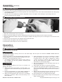
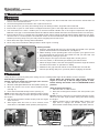

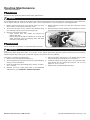

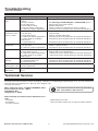
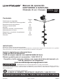


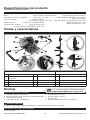
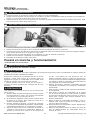
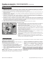
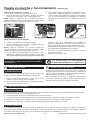
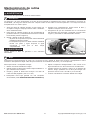
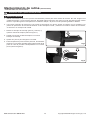


![Powermate P-WLE-1639-[E] User's Manual](http://vs1.manualzilla.com/store/data/006990483_1-9a9892bf0fafc5b84d77a1712d729228-150x150.png)
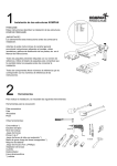
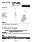

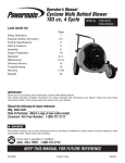


![Powermate P-FTT-160MD-[E] User's Manual](http://vs1.manualzilla.com/store/data/006990492_1-4d5878bcab563735e5d8d0d9941fcade-150x150.png)