1
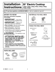
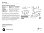
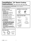
Installation 36" Electric Cooktop
Instructions
CP650, JP655, PP962, PP972, PP975, PP980, ZEU36K
“If you have questions, call 800.GE.CARES or visit our website at: ge.com”
Before You Begin
MATERIALS YOU WILL NEED
Read these instructions completely
and carefully.
IMPORTANT
• — Save these instructions
for local inspector’s use.
IMPORTANT
TOOLS YOU WILL NEED
Pencil
WARNING — This appliance must be
Saber Saw
Phillips Head
Screwdriver
properly grounded.
ATTENTION INSTALLER
— ALL
• COOKTOPS MUST BE HARD WIRED (DIRECT
WIRED) INTO AN APPROVED JUNCTION BOX. A
“PLUG AND RECEPTACLE” IS NOT PERMITTED
ON THESE PRODUCTS.
• Proper installation is the responsibility
of the installer and product failure due to
improper installation is NOT covered under
warranty.
Ruler or Straightedge
Safety Glasses
PARTS INCLUDED
4 Screws
(WB1X1137)
31-10636-2 (11-10 GE)
Wire Nuts
Junction Box
• — Observe all governing
codes and ordinances.
• Note to Installer – Be sure to leave these
instructions with the Consumer.
• Note to Consumer – Keep these instructions for
future reference.
• Product failure due to improper installation is not
covered under the Warranty.
2 Hold Down
Brackets
Foam Tape
1
1/8≤ Drill Bit & Electric or
Hand Drill
Installation Instructions
IMPORTANT SAFETY INSTRUCTIONS
For Your Safety
Electrical Requirements
•For Personal Safety, remove house fuse or open
circuit breaker before beginning installation.
Failure to do so could result in serious injury or
death.
•Be sure your cooktop is installed properly by a
qualified installer or service technician.
•To eliminate the risk of burns or fire due to
reaching over heated surface elements, cabinet
storage located above the surface units should
be avoided. If cabinet storage space is to be
provided, the risk can be reduced by installing a
range hood that projects horizontally a minimum
of 5" beyond the bottom of the cabinets. Cabinet
installation above the cooktop may be no deeper
than 13".
•Make sure the cabinets and wall coverings
around the cooktop can withstand the
temperatures (up to 200°F) generated by the
cooktop.
•The cooktop should be easy to reach and lighted
with natural light during the day.
•Always disconnect the electrical service to
the cooktop before repairing or servicing the
cooktop. This can be done by disconnecting the
fuse or circuit breaker. Failure to do this could
result in a dangerous or fatal shock. Know where
your main disconnect switch is located. If you do
not know, have your electrician show you.
This appliance must be supplied with the proper
voltage and frequency, and connected to an
individual, properly grounded branch circuit,
protected by a circuit breaker or a time delay fuse
as noted on name plate.
We recommend you have the electrical wiring and
hookup of your cooktop connected by a qualified
electrician. After installation, have the electrician
show you where your main cooktop disconnect is
located.
Wiring must conform to National Electrical Code.
You can get a copy of the National Electrical Code,
ANSI/NFPA No. 70-Latest Edition, by writing:
National Fire Protection Association
Batterymarch Park
Quincy, MA 02269
The cooktop conduit wiring is approved for copper
wire connection only, and if you have aluminum
house wiring, you must use special UL approved
connectors for joining copper to aluminum.
You must use a two-wire, three conductor 208/240
VAC, 60 Hertz electrical system. A white (neutral)
wire is not needed for this unit. The cooktop must
be installed in a circuit that does not exceed 125
VAC nominal to ground.
Refer to the name plate on your cooktop for the
KW rating for your cooktop.
Name plate location
2
Installation Instructions
Pre-Installation Checklist
WARNING – The electrical power to
C Remove Installation Instructions from
literature pack and read them carefully before
you begin.
the cooktop supply line must be shut off while
connections are being made. Failure to do so
could result in serious injury or death.
A When preparing cooktop opening, make sure
the inside of the cabinet and the cooktop do
not interfere with each other. (See section on
preparing the opening.)
Be sure to place all literature, Owner’s Manual,
Installations, etc. in a safe place for future
reference.
B Remove packaging materials and literature
package from the cooktop before beginning
installation.
Literature
Package
Styrofoam
Packaging
HOT
D Make sure you have all the tools and materials
you need before starting the installation of the
cooktop.
E Your home must provide the adequate
electrical service needed to safely and
properly use your cooktop. (Refer to section on
electrical requirements.)
ON
F When installing your cooktop in your home,
make sure all local codes and ordinances are
followed exactly as stated.
Cooktop
G Make sure the wall coverings, countertop and
cabinets around the cooktop can withstand
heat (up to 200°F) generated by the cooktop.
3
Installation Instructions
Preparing the Opening
1
4 Cutout dimensions of the
countertop
The following MINIMUM clearance dimensions
must be maintained.
13" MAX. Depth of uprotected
overhead cabinets
2" MIN. Clearance
from cutout to
side wall on the
right of the unit
To insure accuracy, it is best to make a template
when cutting the opening in the counter.
19-1/8" width of cut
30" MIN.
Clearance from
countertop to
unprotected
overhead
surface
15" MIN. Height
from countertop to
nearest cabinet on
either side of unit
1-3/4" Min. Between
cutout and the wall
behind the cooktop
2-1/2" Min.
from front edge
of cutout and
front edge of
countertop
2" MIN. Clearance
from cutout to side
wall on the left of
the unit
If a 30" clearance between the cooking surface
and overhead combustible materials or metal
cabinets cannot be maintained, a minimum
clearance of 24" is required and the underside
of the cabinets above the cooktop must be
protected with not less than 1/4" insulating
millboard covered with sheet metal not less than
0.0122" thick.
5
20-7/8" (21" SS)
Depth on Monogram ZEU36K
is 21-1/4' @ center.
Cooktop
18-7/8"
3
33-3/4"
Five inches (5")
minimum vertical
clearance between
the cooktop bottom
and any combustible
surfaces.
Make sure the wall coverings, countertop and
cabinets around the cooktop can withstand
heat (up to 200°F) generated by cooktop.
Wall covering,
cabinets and
countertop must
withstand heat up
to 200°F.
2 Overall cooktop dimensions
36"
(36-1/8" SS)
33-7/8"
length of
cut
3-1/4" Front
4-5/8" Rear
at the conduit
location
6-1/4" Rear
on Model PP975 &
PP980
5" Min.
Vertical Clearance
4
Installation Instructions
Installing the Cooktop
1 Installing the Junction Box
3 Attach Foam TAPE
Install an approved junction box where it will be
easily reached through the front of the cabinet
where the cooktop will be located. The cooktop
conduit is 4 feet long.
Apply the foam tape around the outer edge of the
glass. Do not overlap the foam tape.
Bottom of Cooktop
Foam Tape
16"
Min.
Cooktop
Glass
Note: On CP650S, PP962S, PP972S, PP975S
& PP980S models, apply the foam tape around the
outer edge of the glass on the sides and rear of
the unit only.
Install junction box so
that it can be reached
through the front of the
cabinet.
4 Locate Mounting Parts
Remove the Hold Down Brackets and screws from
the literature package.
IMPORTANT:
The junction box must be
located where it will allow considerable slack in
the conduit for serviceability.
Mounting Screw
5 Attach Brackets to Cooktop
Screw the Hold Down Bracket to the side
of the cooktop unit. Repeat for opposite side of
cooktop.
2 Protect Surface of Cooktop
Place a towel or tablecloth onto the countertop.
Lay the cooktop upside down onto the protected
surface.
Bottom of cooktop
Bottom of Cooktop
Pre-Drilled Hole
Foam Tape
Cooktop Glass
Cloth under Cooktop
5
Hold Down
Bracket
Installation Instructions
Installing the Cooktop (CONT.)
6 Insert Cooktop Into Cutout
7 Attach Hold Down Brackets
to Cabinet
Insert the cooktop centered into the cutout
opening. Make sure the front edge of the
countertop is parallel to the cooktop. Make final
check that all required clearances
are met.
Open the cabinet door and screw the Hold Down
Brackets to the cabinet sides with the screws
provided.
Mounting Screw
Burner Box Sides
Cooktop
Hold Down
Bracket
Use suitable fasteners for
anchorage in cabinet sides
Cabinet Side
6
Installation Instructions
Installation—Electrical Connections
A When making the wire connections, use the
entire length of conduit provided. The conduit
must not be shortened.
E Once the connections are made, secure wires
together using wire nuts.
Red
B With the cooktop in place, open the front of
the cabinet door.
Strain Relief Clamp
C Insert the wires from the conduit through the
opening of the junction box.
Ground
Red
GROUNDING INSTRUCTIONS:
Strain Relief Clamp
The bare ground wire in the conduit is connected
to the cooktop frame. Effective January 1, 1996,
the National Electrical Code will not permit
grounding through neutral.
If used in new construction after January 1, 1996
or in a mobile home, recreational vehicle or if
local codes do not permit grounding through
the neutral white lead, attach the appliance
grounding lead (green or copper) to the residence
grounding conductor (green or bare copper) in
accordance with local codes. When connecting to
a 3 conductor branch circuit, if local codes permit,
connect the bare ground connector lead of the
cooktop to the branch circuit neutral (gray or
white in color).
Ground
Black
D Connect the red and black leads from the
cooktop conduit to the corresponding leads in
the junction box.
Red
Ground wire
location
Black
Black
IMPORTANT:
If the cooktop is being
installed into a blind counter (one with no cabinet
opening below), wire connections must be made
before putting the cooktop into the cutout
opening.
7
Installation Instructions
Checklists
1 Pre-Test Checklist
2 Operation Checklist
A Remove all protective film, if present, and any
stickers.
A Remove all items from the top of the cooktop
surface.
B Check to be sure that all wiring is secure and
not pinched or in contact with moving parts.
B Turn on the power to the cooktop.
(Refer to your Owner’s Manual.) Verify that all
surface burners operate properly.
C Check level of appliance.
D Check that the cooktop is properly grounded.
C Check that the circuit breaker is not tripped
nor the house fuse blown.
D Check that conduit is securely connected to
the junction box.
E See Owner’s Manual for troubleshooting list.
NOTE TO ELECTRICIAN:
The power leads supplied with this appliance are
UL recognized for connections to larger gauge
household wiring. The insulation of these leads
is rated at temperatures much higher than
the temperature rating of household wiring.
The current carrying capacity of a conductor
is governed by the wire gauge and also the
temperature rating of the insulation around the
wire.
NOTE: ALUMINUM WIRING
• WARNING:
IMPROPER CONNECTION OF ALUMINUM
HOUSE WIRING TO THE COPPER LEADS CAN
RESULT IN A SERIOUS PROBLEM.
• Splice copper wires to aluminum wiring
using special connectors designed and UL
approved for joining copper to aluminum
and follow the manufacturer’s recommended
connector procedure closely.
NOTE: Wire used, location and enclosure of
splices, etc., must conform to good wiring
practice and local codes.
8
Instrucciones Estufa eléctrica de 36"
de instalación
CP650, JP655, PP962, PP972, PP975, PP980, ZEU36K
“Si tiene alguna pregunta, llame al 800.GE.CARES o visite nuestro sitio Web en: ge.com”
ANTES DE COMENZAR
NECESITARÁ
LOS SIGUIENTES MATERIALES
Lea estas instrucciones por completo
y con cuidado.
IMPORTANTE
• — Conserve estas
instrucciones para el uso del inspector local.
IMPORTANTE
• — Cumpla con todos los
códigos y reglas aplicables.
• Nota para el instalador – Asegúrese de dejar estas
instrucciones en poder del consumidor.
•Nota para el consumidor – Conserve estas
instrucciones para referencias futuras.
• El mal funcionamiento del producto debido
a una instalación incorrecta no está cubierto por la
Garantía.
Caja de empalmes
Tuercas para cables
NECESITARÁ LAS SIGUIENTES
HERRAMIENTAS
Lápiz
ADVERTENCIA
— Este aparato debe
descargarse a tierra correctamente.
Sierra
Destornillador Phillips
ATENCIÓN INSTALADOR
—
• TODAS LAS ESTUFAS DEBEN CONTAR CON
CABLEADO (CABLEADO DIRECTO)
A UNA CAJA DE EMPALMES APROBADA.
ESTOS PRODUCTOS NO ACEPTAN ENCHUFES Y
RECEPTÁCULOS.
• La instalación correcta es responsabilidad
del instalador, y el mal funcionamiento del
producto debido a una instalación inadecuada NO
está cubierto bajo la garantía.
Regla o
regla para nivelar
Gafas de seguridad
PARTES INCLUIDAS
4 Tornillos
(WB1X1137)
2 abrazaderas
de montaje
Cinta de espuma
31-10636-2 (11-10 GE)
1
Broca perforadora de 1/8≤
y taladro eléctrico o manual
Instrucciones de instalación
INSTRUCCIONES DE SEGURIDAD IMPORTANTES
PARA SU SEGURIDAD
REQUISITOS ELÉCTRICOS
•Para su seguridad personal, retire los fusibles de
su hogar o bien abra el cortacircuitos antes de
comenzar con la instalación. El no hacerlo puede
resultar en lesiones serias o incluso la muerte.
•Asegúrese que su estufa sea instalada
correctamente por un instalador o técnico de
servicio calificado.
•Para eliminar el riesgo de quemaduras
o incendio debido al contacto con los elementos
de superficie calentados, debe evitarse el
almacenaje en los gabinetes ubicados sobre
los elementos de superficie. Si se cuenta con
espacio en un gabinete, puede reducir el riesgo
instalando una campana que se proyecte
horizontalmente un mínimo de 5" más del fondo
de los gabinetes. La instalación de gabinetes
sobre la estufa no debe exceder 13"
de profundidad.
•Asegúrese que los gabinetes y las cubiertas
de las paredes alrededor de la estufa puedan
soportar las temperaturas generadas por la
estufa (hasta 200 °F).
•La estufa debe ser fácil de alcanzar y deberá
contar con iluminación natural durante el día.
•Siempre desconecte la toma eléctrica que va
hacia la estufa antes de reparar o dar servicio
a la estufa. Esto puede hacerse desconectando
el fusible o cortacircuitos. No hacer esto puede
resultar en un shock eléctrico peligroso o fatal.
Sepa en dónde se localiza el interruptor principal
de desconexión. Si no lo sabe, pídale a su
electricista que le muestre la ubicación.
Este aparato debe contar con el voltaje y
frecuencia adecuados, y deberá conectarse
a un circuito derivado individual debidamente
descargado a tierra, protegido por un cortacircuitos
o un fusible temporizado como lo indica la placa.
Le recomendamos que un electricista calificado
conecte el cableado eléctrico y conexión de
su estufa. Después de la instalación, pídale al
electricista que le muestre en dónde se localiza el
interruptor principal de desconexión de su estufa.
El cableado debe cumplir con el Código Nacional
sobre Electricidad. Puede obtener una copia del
Código Nacional sobre Electricidad, ANSI/NFPA No.
70-Última edición, escribiendo a:
Asociación Nacional
para la Prevención de Incendios
Batterymarch Park
Quincy, MA 02269
El cableado conductor de la estufa está aprobado
para conexiones únicamente con cables de cobre,
y si cuenta con cableado de aluminio, debe usar
conectores especiales aprobados por UL para unir
cobre con aluminio.
Debe usar un sistema eléctrico con conductor de
dos cables y tres conductores 208/240 VCA, de
60 Hertz. No se requiere un cable blanco (neutral)
para esta unidad. La estufa debe instalarse en
un circuito que no exceda 125 VCA nominales de
descarga a tierra.
Consulte el rótulo sobre su estufa para conocer la
clasificación en kilovatios de su estufa.
Ubicación del rótulo
2
Instrucciones de instalación
LISTA DE VERIFICACIÓN PREVIA A LA INSTALACIÓN
ADVERTENCIA – La corriente
C Saque las instrucciones de instalación del
paquete de material impreso y léalas
cuidadosamente antes de comenzar.
eléctrica a la tubería de abastecimiento de la
estufa debe cortarse durante la realización de
conexiones. El no hacerlo puede resultar en una
lesión seria o la muerte.
A Cuando se prepare para la abertura de la
estufa, asegúrese que el interior del gabinete
y la estufa no interfieran uno con el otro.
(Consulte la sección de preparación
de la abertura).
Asegúrese de colocar todo el material
impreso, Manual de propietario, Instalaciones,
etc., en un lugar seguro para referencia
futura.
B Retire los materiales de empaque y el material
impreso de la estufa antes de comenzar la
instalación.
Paquete de
material impreso
Empaque de espuma
de poliestireno
HOT
D Asegúrese de contar con todas las
herramientas y materiales que necesita antes
de comenzar la instalación de la estufa.
E Su hogar debe contar con el servicio eléctrico
adecuado para el uso seguro y correcto de su
estufa. (Consulte la sección de requisitos
eléctricos).
ON
F Cuando instale la estufa en su hogar,
asegúrese de cumplir todos los códigos y
reglas locales tal y como se establecen.
Estufa
G Asegúrese de que las cubiertas de las
paredes, el mostrador y los gabinetes
alrededor de la estufa puedan soportar las
temperaturas generadas por la estufa (hasta
200 °F).
3
Instrucciones de instalación
PreparACIÓN DE LA ABERTURA
1
4 DIMENSIONES DEL ÁREA
CORTADA EN EL MOSTRADOR
Deben seguirse las siguientes dimensiones
MÍNIMAS de espacio libre.
13" MÁX. Profundidad de los gabinetes
superiores sin protección
2" MÍN. Espacio
desde el área
cortada hasta
la pared lateral
a la derecha
de la unidad
30" MÍN.
Espacio desde
el mostrador
hasta la superficie
superior sin
protección
Para garantizar la precisión, es mejor crear una
plantilla al momento de cortar la abertura en el
mostrador.
19-1/8" ancho del corte
15" MÍN. Altura
desde
el mostrador
hasta el
gabinete más
cercano a
cualquiera
de los lados
de la unidad
2" MÍN. Espacio desde
el área cortada hasta
la pared lateral a la
izquierda de la unidad
1-3/4" Mín. Entre
el área cortada y
la pared detrás
de la estufa
2-1/2" MÍn.
del borde frontal del
área cortada
y el borde frontal del
mostrador
Si no puede mantenerse un espacio de 30" entre
la superficie de cocción y los materiales superiores
inflamables o gabinetes metálicos, se requiere
un espacio mínimo de 24", así como que el lado
inferior de los gabinetes encima de la estufa estén
protegidos con no menos de 1/4" de cartón gris
aislante cubierto con láminas metálicas de no
menos de 0.0122" de grosor.
5
20-7/8" (21" AO [acero inoxidable])
La profundidad en Monogram ZEU36K
es de 21-1/4" en el centro.
Estufa
18-7/8"
3
33-3/4"
Espacio vertical
mínimo de cinco
pulgadas (5”) entre
la parte inferior de
la estufa y cualquier
tipo de superficie
inflamable.
Asegúrese que las cubiertas de las paredes, el
mostrador y los gabinetes alrededor de la
estufa puedan soportar las temperaturas
generadas por la estufa (hasta 200 °F).
La cubierta
de la pared, los
gabinetes y el
mostrador deben
soportar calor
hasta 200 °F.
2 DIMENSIONES
GENERALES DE LA ESTUFA
36"
(36-1/8≤ AO)
33-7/8"
longitud
del corte
3-1/4" Frente
4-5/8" Parte
posterior en la
ubicación del
conducto
6-1/4" Parte
posterior en los
modelos PP975 y
PP980
5" Mín. de espacio
vertical
4
Instrucciones de instalación
InstaLACIÓN DE LA ESTUFA
1 InstalACIÓN DE LA CAJA DE EMPALMES
3 APLIQUE LA CINTA DE ESPUMA
Aplique la cinta de espuma alrededor del borde
externo del vidrio. No aplique un exceso de cinta
de espuma.
Instale una caja de empalmes aprobada en
un lugar de fácil acceso a través del frente del
gabinete en donde pueda colocarse la estufa.
El conducto de la estufa tiene 4 pies de longitud.
Parte inferior de la estufa
Cinta de espuma
16"
Mín.
Vidrio de
la estufa
Nota: En los modelos CP650S, PP962S, PP972S,
PP975S y PP980S, aplique la cinta de espuma
únicamente alrededor del borde exterior
del vidrio en los lados y parte posterior
de la unidad.
Instale la caja de
empalmes de modo que
pueda alcanzarse
a través del frente
del gabinete.
4 LocaLICE LAS PARTES
DE MONTAJE
IMPORTANTE:
La caja de empalmes
debe localizarse en donde el conducto esté lo
suficientemente flojo para permitir que
se le dé servicio.
Saque las abrazaderas de montaje y tornillos del
empaque con material impreso.
Tornillo de montaje
2 ProtecCIÓN DE
LA SUPERFICIE DE LA ESTUFA
5 SUJETE LAS ABRAZADERAS
A LA ESTUFA
Coloque una toalla o mantel sobre el mostrador.
Coloque la estufa al revés sobre
el área protegida.
Atornille la abrazadera de montaje a un lado de la
unidad de la estufa. Repita en el lado opuesto de la
estufa.
Parte inferior de la estufa
Parte inferior de la estufa
Agujero
previamente
perforado
Cinta de espuma
Paño debajo de la estufa
Vidrio de la estufa
5
Abrazadera
de montaje
Instrucciones de instalación
InstalACIÓN DE LA ESTUFA (CONT.)
6 InsertE LA ESTUFA EN EL ÁREA CORTADA
7 SUJETE
LAS ABRAZADERAS DE MONTAJE
AL GABINETE
Inserte la estufa centrada en el área cortada.
Asegúrese de que el borde frontal del mostrador
esté paralelo con respecto a la estufa. Asegúrese
de verificar al final que todos los espacios
especificados hayan sido respetados.
Abra la puerta del gabinete y atornille
las abrazaderas de montaje a los lados
del gabinete con los tornillos incluidos.
Estufa
Tornillo de montaje
Lados de la caja
de hornillas
Abrazadera
de montaje
Use sujetadores adecuados
para fijación a los lados del
gabinete
Lado del gabinete
6
Instrucciones de instalación
InstalACIÓN—CONEXIONES ELÉCTRICAS
A Cuando realice las conexiones de cables,
utilice toda la extensión del conducto incluido.
El conducto no debe reducirse.
E Una vez que se hayan realizado las
conexiones, fije los cables con las tuercas
para cables.
B Con la estufa colocada en su lugar, abra el
frente de la puerta del gabinete.
Rojo
C Inserte los cables del conducto a través de la
abertura de la caja de empalmes.
Pinza de alivio de tensión
Descarga a tierra
Rojo
Pinza de alivio de tensión
INSTRUCCIONES PARA DESCARGA A TIERRA:
El cable pelado de descarga a tierra en el
conducto se conecta al armazón de la estufa. A
partir del 1 de enero de 1996, el Código Nacional
sobre Electricidad no permitirá la descarga a
tierra a través de cables neutrales. Si se usa en
una construcción nueva después del 1 de enero
de 1996 o bien en una casa rodante, vehículo
recreativo, o bien si los códigos locales no
permiten la descarga a tierra a través de cables
blancos neutrales, sujete el cable de descarga a
tierra del aparato (verde o cobre) al conductor de
descarga a tierra de la residencia (verde o cobre)
de acuerdo con los códigos locales. Cuando
conecte a un circuito derivado de 3 conductores,
si lo permiten los códigos locales, conecte el
cable del conector de descarga a tierra al circuito
derivado neutral (de color gris o blanco).
Descarga a tierra
Negro
D Conecte los cables rojo y negro del conductor de
la estufa a los cables correspondientes en la
caja de empalmes.
Rojo
Ubicación del cable de
descarga a tierra
Negro
Negro
IMPORTANTE:
Si la estufa se va
a instalar en un mostrador sin salida (uno sin
abertura del gabinete inferior), las conexiones del
cableado deberán realizarse antes de colocar la
estufa en el área cortada.
7
Instrucciones de instalación
LISTAS DE VERIFICACIÓN
1 LISTA DE VERIFICACIÓN PREVIA
2 LISTA DE VERIFICACIÓN
DE OPERACIÓN
A Retire toda la película protectora,
si la hay, y las calcomanías.
A Retire todos los objetos que se encuentren
sobre la superficie de la estufa.
B Verifique que todos los cables estén
fijos y que no estén torcidos o en contacto
con partes móviles.
B Encienda la toma de corriente de la estufa.
(Consulte su Manual del propietario). Verifique
que todas las hornillas de la superficie
funcionen correctamente.
C Verifique el nivel del aparato.
D Verifique que la estufa esté descargada
a tierra correctamente.
C Verifique que el cortacircuitos no esté
desactivado o que se haya fundido el fusible
de su hogar.
D Verifique que el conducto esté conectado
correctamente a la caja de empalmes.
E Consulte el Manual del propietario para ver la
lista de resolución de problemas.
NOTA PARA EL ELECTRICISTA:
Los cables de corriente incluidos con este
aparato cuentan con la aprobación de UL para
conexiones a cableado doméstico de mayor
calibre. El aislante de estos cables se califica a
temperaturas más elevadas que las del cableado
doméstico. La capacidad de carga actual de
un conductor depende del calibre del cable y
también de la calificación de la temperatura del
aislante alrededor del cable.
NOTA: CABLEADO DE ALUMINIO
• ADVERTENCIA:
LA CONEXIÓN INADECUADA DEL CABLEADO
DOMÉSTICO DE ALUMINIO A LOS CABLES DE
COBRE PUEDE RESULTAR EN UN PROBLEMA
GRAVE.
• Una los cables de cobre a los de aluminio con
conectores especiales diseñados y aprobados
por UL para unir cables de cobre a cables de
aluminio; asimismo, siga cuidadosamente las
recomendaciones del fabricante al manipular
el conector.
NOTA: El uso de los cables, la ubicación
y alojamiento de empalmes, etc., deben
realizarse correctamente y de acuerdo con los
códigos locales.
8