1
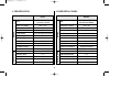
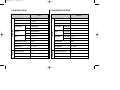
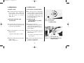
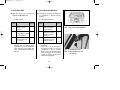
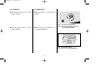
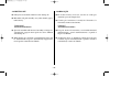
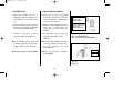
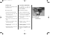
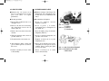
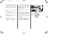
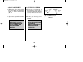
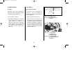
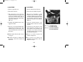
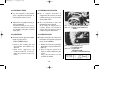
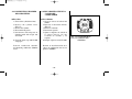
OWNER'S MANUAL
MANUAL DEL PROPIETARIO
HEAD OFFICE(FACTORY)
OFICINA CENTRAL (FÁBRICA)
#58, SUNG SAN-DONG, CHANG WON, KYUNGNAM, KOREA
TEL: (82-55) 239-7000 / FAX: (82-55) 239-7524
OM11-0108-08E,S
LIBERTY02.11.55:44PM페이지1
CONTENTS
CONTENIDO
1. SPECIFICATION.................................................... 3
1. ESPECIFICACIONES........................................... 3
2. OPERATION
2-1. FUEL COCK ...................................................... 5
2-2. FILLING OF FUEL AND ENGINE OIL........ 5
2-3. IGNITION KEY..................................................6
2-4. STARTING ......................................................... 7
2-5. CHECK POINTS WHEN ENGINE FAILS
TO START .......................................................... 9
2-6. DRIVING OFF................................................. 10
2-7. DRIVING ON SLOPES .................................. 11
2-8. BRAKING ........................................................ 12
2-9. TURN SIGNALS AND HORN ..................... 13
2-10. HEAD LIGHT AND TAIL & STOP
LIGHT............................................................... 14
2-11. SPEEDOMETER & ODOMETER................ 15
2. OPERACIÓN
2-1. LLAVE DE COMBUSTIBLE .......................... 5
2-2. LLENADO DE COMBUSTIBLE Y
ACEITE DEL MOTOR..................................... 5
2-3. LLAVE DE ENCENDIDO ............................... 6
2-4. ARRANQUE...................................................... 7
2-5. PUNTOS A REVISAR SI HAS FALLOS
EN EL MOTOR ................................................. 9
2-6. ARRANQUE.................................................... 10
2-7. MANEJO EN PENDIENTES......................... 11
2-8. FRENOS........................................................... 12
2-9. GUIÑADORES Y BOCINA.......................... 13
2-10. LUCES DELANTERA, TRASERA Y DE
PARADA .......................................................... 14
2-11. VELOCIMETRO Y ODOMETRO ............... 15
3. CHECK POINTS FOR MAXIMUM
PERFORMANCE
3-1. DAILY CHECK ............................................... 16
3-2. REGULARLY SCHEDULED CHECK ........ 17
3. PUNTOS A REVISAR POR MAXIMO
RENDIMIENTO
3-1. REVISIÓN DIARIA........................................ 16
3-2. REVISIONES REGULARES
PROGRAMADAS .......................................... 17
-1-
LIBERTY02.11.55:44PM페이지2
CONTENTS
CONTENIDO
4. MAINTENANCE AND LUBRICATION
4-1. ENGINE OIL ................................................... 18
4-2. GEAR OIL........................................................ 19
4-3. SPARK PLUG.................................................. 21
4-4. FUEL COCK.................................................... 22
4-5. AIR CLEANER ............................................... 23
4-6. THROTTLE CABLE ADJUSTMENT ......... 24
4-7. CARBURETOR ADJUSTMENT.................. 25
4-8. BRAKE ADJUSTMENT................................ 26
4-9. DRIVE CHAIN................................................ 27
4-10. BATTERY ........................................................ 29
4-11. FUSE REPLACEMENT................................. 30
4-12. IGNITION TIME............................................. 31
4-13. MUFFLER........................................................ 31
4-14. CUMBUSTION CHAMBER
DECARBONIZING ........................................ 32
4. MANTENIMIENTO Y LUBRICACIÓN
4-1. ACEITE DEL MOTOR .................................. 18
4-2. ACEITE DE LA CAJA DE CAMBIOS ........ 19
4-3. BUJÍA DE ENCENDIDO............................... 21
4-4. LLAVE DE COMBUSTIBLE ........................ 22
4-5. LIMPIADOR DE AIRE .................................. 23
4-6. AJUSTE DEL CABLE DEL OBTURADOR ... 24
4-7. AJUSTE DEL CARBURADOR .................... 25
4-8. AJUSTE DEL FRENO.................................... 26
4-9. CADENA ......................................................... 27
4-10. BATERÍA ......................................................... 29
4-11. REEMPLAZO DEL FUSIBLE ...................... 30
4-12. TIEMPO DE IGNICIÓN ................................ 31
4-13. SILENCIADOR ............................................... 31
4-14. DECARBONIZACIÓN DE LA
CAMARA DE COMBUSTIBLE .................. 32
-2-
LIBERTY02.11.55:44PM페이지3
1. SPECIFICATION
ITEM
TYPE
BORE AND STROKE
1. ESPECIFICACIONES
CARACTERÍSTICA
DATA
AIR-COOLED, ONE
CYLINDER, 2 STROKE
TIPO
40 X 39.5mm
DIAMETRO Y CARRERA
DATOA
UN CILINDRO, ENFRIADO
POR AIRE, DOS TIEMPOS
40 X 39.5mm
49.6cc
DESPLAZAMIENTO DEL PISTON
49.6cc
COMPRESSION RATIO
6.5:1
RAZON DE COMPRESIÓN
6.5:1
CARBURETOR
VM 13(LEADED/UNLEADED)
IGNITION TYPE
POINTLESS
OIL CAPACITY
1.2 ℓ
PS/RPM.
3/6,000
TORQUE/RPM.
MOTOR
ENGINE
PISTON DISPLACEMENT
0.36/6,000
CARBURADOR
TIPO DE IGNICIÓN
VM 13(PLOMO/SIN PLOMO)
SIN AGUJAS
CAPACIDAD DE ACEITE
1.2 ℓ
PS/RPM
3/6,000
TORQUE/RPM
0.36/6,000
KICK/ELECTRIC
SISTEMA DE ARRANQUE
RÁPIDO / ELECTRICO
CLUTCH SYSTEM
CENTRIFUGAL AUTOMATIC
SISTEMA DE EMBRAGUE
CENTRIFUGO AUTOMATICO
TIPO
AUTOMATICO, 2 CAMBIOS
TYPE
AUTOMATIC 2 SHIFT
PRIMARY DRIVE
4,353
GEAR RATIO 1
1,350
GEAR RATIO 2
2,750
FINAL DRIVE
3,667
TRANSMISIÓN
TRANSMISSION
STARTING SYSTEM
-3-
PROPULSIÓN PRIMARIA
4,353
RAZON DE ENGRANAJES 1
1,350
RAZON DE ENGRANAJES 2
2,750
PROPULSIÓN FINAL
3,667
LIBERTY02.11.55:44PM페이지4
1. SPECIFICATION
1. ESPECIFICACIONES
ITEM
CARACTERÍSTICA
DATA
DATOA
TYPE
TUBULAR
TIPO
TUBULAR
WHEEL BASE
1,150mm
BASE DE LA RUEDA
1,150mm
SEAT HEIGHT
750mm
ALTURA DEL ASIENTO
750mm
FR.
TELESCOPIC
SUSPENSIÓN
RR.
SWING ARM (OIL)
FR.
DRUM BRAKE
RR.
DRUM BRAKE
FR.
2,25 X 17″
RR.
GROUND CLEARANCE
2.25 X 17″
140mm
ESPACIO LIBRE
140mm
FUEL CAPACITY
5.5ℓ
CAPACIDAD COMBUSTIBLE
5.5ℓ
RAKE/TRAIL
64˚ / 70mm
RASTRO/COLA
64˚ / 70mm
SUSPENSION
TIRE
TRASERO
CHASIS
CHASSIS
BRAKE
CHARGE CONTROL
REGULATOR RECTIFIER
BATTERY CAPACITY
12V4AH
DELANTERO ZAPATA DEL FRENO
TRASERO
NEUMATICO
BRAZO L’OCO
ZAPATA DEL FRENO
DELANTERO 2,25 X 17″
2.25 X 17″
LARGO X ANCHO X ALTURA 1,790 X 685 X 1,020 mm
ELÉCTRICO
ELE.
12V
FRENOS
TRASERO
OVERALL LEG X WDT X HGT 1,790 X 685 X 1,020 mm
POWER SOURCE
DELANTERO TELESCÓPICO
-4-
FUENTE DE POTENCIA
12V
CONTROL DE CARGA
RECTIFICADOR DEL REGULADOR
CAPACIDAD DE BATERÍA
12V4AH
LIBERTY02.11.55:44PM페이지5
2. OPERATION
2. OPERACIÓN
2-1 FUEL COCK
2-1 LLAVE DE COMBUSTIBLE
■
To open the fuel cock, turn the lever
into position ‘ON’. When the
engine stops due to lack of fuel, just
turn the lever to position
‘RES’.(ILL.1)
2-2 FILLING OF FUEL AND
ENGINE OIL
■
Para abrir la llave de combustible,
mover la palanca a la posición ON.
Cuando el motor se detiene por falta
de combustible, lo único que tiene
que hacer es mover la palanca a la
posición RES (FIG. 1)
2-2 LLENADO DE
COMBUSTIBLE Y ACEITE
DEL MOTOR
■
To fill the fuel tank, turn the cap
counterclockwise then fill with
regular fuel (gasolin)(ILL.2)
■
Para llenar el tanque de
combustible, sacar la tapa dando la
vuelta en sentido anti-horario y
luego llenar el tanque con gasolina
normal. (FIG.2)
■
Turn cap clockwise to close after
filling fuel tank.
■
Luego de llenar el tanque, colocar la
tapa otra vez, dando la vuelta en
sentido horario.
(ILL. 1) FUEL COCK
(FIG. 1) LLAVE DE
COMBUSTIBLE
- Capacity of fuel tank is 5.5 liters.
- La máxima capacidad del tanque
es de 5.5 litros.
■
Whenever filling the fuel, check the
engine oil also.
(Refer to Chapter 4-1)
■
Revisar el aceite del motor cada vez
que llene el combustible.
(remitirse al capítulo 4-1)
-5-
(ILL. 2) ① FUEL TANK CAP
(FIG. 2) ① TAPA DEL TANQUE DE
COMBUSTIBLE
LIBERTY02.11.55:44PM페이지6
2-3 LLAVE DE ENCENDIDO
2-3 IGNITION KEY
■
With just one key, you can use for
lgnition and Handle Lock.
① Main switch
■
Usted puede usar una sola llave para
el encendido y bloqueo delas
manijas.
① Interruptor principal
Key
Key
Function
Position
Removal
OFF
Engine and all electric YES
circuit cannot be
operated.
ON
Only engine can be
NO
started. Electric circuit
can be operated.
RUN
Start to drive.
Electric circuit can
be operated.
NO
② Handle-bar lock
Handle-bar are locked when
ignition key is turned clockwise
after insertion in handle-bar
lock, with handle-bar turned to
the left.
Posición
Remover
Función
de la llave
la llave
OFF
No se puede operar
Sí
el motor ni ningún
circuito eléctrico.
ON
Sólo puede arrancar NO
el motor. Se pueden
operar los circuitos
eléctricos.
RUN Empezar a conducir. NO
Se pueden operar los
circuitos eléctricos.
② Bloqueo de la manija de
dirección
Las barras de la manija se
bloquean cuando la llave de
encendido se gira en sentido
horario, luego de insertarla en la
barra de bloqueo de las manijas
cuando la manija de dirección
está hacia la izquierda.
-6-
(ILL. 3) IGNITION KEY
(FIG. 3) LLAVE DE ENCENDIDO
(ILL. 4) HANDLE LOCK
(FIG. 4) BLOQUEO DE LAS
MANIJAS
LIBERTY02.11.55:44PM페이지7
2-4. STARTING
■
■
Turn the fuel cock lever into ‘ON’
position. (ILL.5)
Turn the ignition key to ‘ON’
position. (ILL.6)
2-4. ARRANQUE
■
■
Mover la palanca a la posición ON
(FIG. 5)
Girar la llave de encendido a la
posición ON.(FIG. 6)
(ILL. 5) FUEL COCK LEVER
(FIG. 5) PALANCA DE LA LLAVE
DE COMBUSTIBLE
(ILL. 6) IGNITION KEY
(FIG. 6) LLAVE DE ENCENDIDO
-7-
LIBERTY02.11.55:44PM페이지8
■
Be sure to hold the rear brake lever
for your safety when starting the
engine.
■
Por su seguridad, asegurarse de
sujetar la palanca del freno trasero
cuando arranque el motor.
■
With Cold Engine
Pull the choke knob, then press the
starter button. Do not operate the
throttle. After starting, be sure to
place the choke lever to original
position.(ILL. 7)
■
Con el motor frío
Jalar la perilla del estrangulador de
aire, luego apretar el botón de
arranque. No use el obturador.
Luego del arranque, asegurarse de
poner la perilla del estrangulador a
su posición original.(FIG. 7)
■
With Warm Engine
Do not use the choke. Open the
throttle slightly, then start the
engine by starter button.(ILL. 8)
■
Con el motor tibio
No usar el estrangulador. Abrir el
obturador, luego arrancar el motor
con el botón de arranque.(FIG. 8)
■
After starting the engine, release
rear brake lever. Then you can
enjoy the smooth starting owing to
automatic clutch system by twisting
the throttle grip.
■
Luego de arrancar el motor, soltar la
palanca del freno trasero. Luego
puede disfrutar de un arranque
parejo debido al sistema automático
de embrague haciendo girar el
mango del obturador.
■
You can use kick starter instead of
electric starter when needed.
■
Puede usar el arrancador rápido en
vez del eléctrico cuando sea
necesario.
Note:
Nota:
Do not keep starter button pressed for more
than 5 consecutive seconds. If engine fails to
start, wait approximately 30 seconds before
pressing starter button again.
No apriete el botón de arranque por más de 5
segundos en forma continua.
Si el motor falla en el arranque, esperar más o
menos 30 segundos antes de apretar otra vez el
botón de arranque.
-8-
(ILL. 7) CHOKE KNOB
(FIG. 7) PERILLA DEL
ESTRANGULADOR
(ILL. 8) ① ELECTRIC STARTER
BUTTON
(FIG. 8) ① BOTÓN DE ARRANQUE
LIBERTY02.11.55:44PM페이지9
2-5 CHECK POINTS WHEN
ENGINE FAILS TO START
2-5 PUNTOS A REVISAR SI HAS
FALLOS EN EL MOTOR
1) Fuel level in fuel tank.
1) Nivel de combustible en el tanque
2) Electric starter ; Starter motor, button, battery.
2) Arrancador eléctrico ; motor, botón de arranque, batería
3) Contamination of carburetor.
3) Contaminación en el carburador
4) Contamination of air cleaner element.
4) Contaminación del elemento limpiador de aire
5) Contamination of spark plug and clearance of electrodes
of spark plug
5) Contaminación y separación de los electrodos en la bujía
de encendido
6) Clogging at fuel cock or in fuel line
6) Obstrucción en la llave o línea de combustible
AVOID RUNNING THE ENGINE FOR LONG
PERIODS WHEN YOUR MOTORBIKE IS
STATIONARY.
OTHERWISE, ENGINE WILL BE ADVERSELY
AFFECTED AND FUEL WASTED.
EVITAR TENER EL MOTOR ENCENDIDO
POR LARGO TIEMPO CUANDO SU
MOTOCI-CLETA ESTA PARADA, DE OTRA
MANERA EL MOTOR SERA AFECTADO Y
SE DESPERDICIARA EL COMBUSTIBLE.
-9-
LIBERTY02.11.55:44PM페이지10
2-6 DRIVING OFF
2-6 ARRANQUE
■
Liberty has an automatic clutch for easier driving-off.
■
El modelo Liberty tiene un sistema de embrague
automático para un arranque fácil.
■
Motorbike will pull smoothly away when throttle grip is
turned slowly.
■
Cuando gire lentamente la manija del obturador, la
motocicleta arrancará suavemente.
[Advantages]
Automatic transmission
[Ventajas]
Transmisión automática
■
Speed of motorbike will increased smoothly as 2nd gear is
automatically engaged when speed rises above 30km/h
after driving off.
■
Luego de arrancar la motocicleta, su velocidad aumentará
uniformemente y pasará automáticamente a segunda al
llegar a los 30km/h.
■
When driving up a steep hill, a powerful driving force will
be obtained when 1st gear is automatically engaged after
travel speed is reduced below 35km/h.
■
Al subir una cuesta, se obtendrá la potencia necesaria para
la subida al pasar automáricamente a primera cuando la
velocidad baje a menos de 35km/h.
- 10 -
LIBERTY02.11.55:44PM페이지11
2-7 DRIVING ON SLOPES
2-7 MANEJO EN PENDIENTES
Uphill
Cuesta arriba
When driving uphill, turn accelerator
grip slowly to maintain engine speed
flexibility, whereupon 1st gear or 2nd
gear is automatically engaged
according to degree of slope and speed
of motorbike, providing a comfortable
ride.
Cuando conduzca cuesta arriba, girar
la manija del acelerador lentamente a
fin de mantener la flexibilidad del
motor, luego de lo cual el cambio de
primera a segunda se hará en forma
automática de acuerdo a la inclinación
de la pendiente y la velocidad de la
motocicleta, proporcionando así un
manejo cómodo.
Downhill
Cuesta abajo
When driving downhill, completely
shut off accelerator grip, applying
front and rear brakes slowly.
Cuando conduzca cuesta abajo,
disminuya la velocidad aplicando
lentamente presión a los frenos
delantero y trasero.
- 11 -
LIBERTY02.11.55:44PM페이지12
2-8 BRAKING
■
2-8 FRENOS
Practice stopping with either brakes.
Use both front and rear brakes for maximum braking
efficiency and for your safety.
For stopping, you just close the throttle. Then the engine
will continue to run idle speed,and turn the ignition key to
‘OFF’ position via ‘ON’ position from ‘RUN’position.
Close the fuel cock.
■
CHECK BRAKE EVERY TIME BEFORE YOU
RIDE MOTORBIKE.
Practicar el frenado con ambos frenos.
Use ambos frenos, delantero y trasero, para una máxima
eficiencia en el frenado y seguridad suya.
Para detener la motocicleta, solamente cierre el obturador.
Entonces el motor continuará en marcha lenta, ponga la
llave de ignición en la posición OFF y cierre la llave de
combustible.
REVISAR LOS FRENOS CADA VEZ QUE
MANEJE LA MOTOCICLETA.
- 12 -
LIBERTY02.11.55:44PM페이지13
2-9 TURN SIGNALS AND HORN
2-9 GUIÑADORES Y BOCINA
■
During riding, you can simply
operate turn signal lights by using
the switch on left handle lever
holder. Also you can see blinking
indicator lamps on speedometer
panel which blinks according to
your turning direction. (ILL. 11)
■
Cuando conduzca, usted puede
operar fácilmente los guiñadores
usando el interruptor en la palanca
de la manija izquierda. Además,
puede ver las luces indicadoras de
dirección en el panel del
velocímetro las cuales parpadean de
acuerdo con la dirección de
izquierda. (FIG. 11)
■
You can easily sound the horn by
pressing the horn button on left
handle lever holder. (ILL. 11)
■
También puede hacer sonar la
bocina apretando el botón de la
bocina en la palanca de la manija
derecha. (FIG. 11)
※Battery power will be wasted if
horn is over-used.
※El exceso de uso de la bocina
desperdiciará la potencia de la
batería.
- 13 -
(ILL. 11) ①HORN BUTTON
②TURN SIGNAL S/W
(FIG. 11) ①BOTÓN DEL
BOCINA.
②INTERRUPTOR DEL
GUIÑADOR
LIBERTY02.11.55:44PM페이지14
2-10 HEAD LIGHT AND TAIL
AND STOP LIGHT
2-10 LUCES DELANTERA,
TRASERA Y DE PARADA
■
On the left handle lever holder, you
can use head light switch for nighttime driving.(ILL.12)
■
Para manejar de noche, puede
encender la luz delantera utilizando
el interruptor ubicado en la palanca
de la manija izquierda.(FIG. 12)
■
During running stop light will be
lighted by holding one of both left
and right brake lever.
■
Cuando esté conduciendo, la luz de
parada se encenderá al apretar una
de las manijas de freno, ya sea la
derecha o izquierda.
Whenever head light switch is
turned on, tail light is also turned
on.
■
■
Cuando se enciende la luz delantera,
la luz trasera se encenderá también.
- 14 -
(ILL. 12) ①HEAD LIGHT S/W
(FIG. 12) ①INTERRUPTOR DE LA
LUZ DELANTERA
LIBERTY02.11.55:44PM페이지15
2-11 SPEEDOMETER AND
ODOMETER
■
You can easily find out the running
speed by the speedometer.
The maximum speed shown on
speedometer is 70km/h. The Red
Colored Zone over 40 km/h warns
dangerous speed for your safe
driving.(ILL. 13)
2-11 VELOCIMETRO Y
ODÓMETRO
■
Se puede saber fácilmente la
velocidad a la que se está conduciendo usando el velocímetro.
La velocidad máxima mostrada es
de 70km/h. La zona coloreada en
rojo sobre 40km/h advierte al
conductor sobre velocidares
peligrosas para un manejo
seguro.(FIG. 13)
■
Speedometer will be illuminated
for easier reading when headlight
is turned on when driving in night.
■
Al conducir de noche, el panel
medidor se iluminará para una
fácil lectura cuando encienda la
luz delantera.
■
Regular service periods can be
confirmed with the odometer
enclosed in the speedometer dial,
as the former shows total distance
travelled.
■
Se pueden confirmar los períodos
de servicio a la máquina
chequeando el odómetro que
muestra la distancia total
recorrida.
- 15 -
(ILL. 13) SPEEDOMETER
(FIG. 13) VELOCIMETRO
LIBERTY02.11.55:44PM페이지16
3. CHECK POINTS FOR MAXIMUM
PERFORMANCE
3. PUNTOS A REVISAR POR MAXIMO
RENDIMIENTO
3-1 DAILY CHECK
3-1 REVISIÓN DIARIA
1. Engine oil level in oil tank.
2. Gear oil level in transmission
·Use SAE 15W/40 oil
·Q'ty : 150cc
3. Fuel level in fuel tank
4. Air pressure in tire
·Front : 1.75kg/㎠
·Rear : 2.0kg/㎠
5. Front & rear brake
6. Electric equipment
·Head light, horn, turn signals and tail & stop lights
7. Drive chain lubrication
8. Handle operation
9. Back mirror adjustment
10. Fitness of important bolts & nuts
11. Battery electrolyte
12. Throttle grip operation
1. Nivel del aceite de motor en el tanque de aceite.
2. Nivel de aceite de la caja de cambios.
·Use aceite SAE 15W/40
·Cantidad : 150cc
3. Nivel de combustible en el tanque.
4. Presión de aire en los neumáticos.
·Delantero : 1.75kg/㎠
·Trasero : 2.0kg/㎠
5. Frenos delantero y trasero.
6. Equipo eléctrico
·Luz delantera, bocina, guiñadores y luces trasera y de
parada.
7. Lubricación de la cadena.
8. Operación de las manijas.
9. Ajuste del espejo retrovisor.
10. Ajuste de pernos y tuercas importantes.
11. Electrólito de la batería.
12. Operación del control del obturador.
- 16 -
LIBERTY02.11.55:44PM페이지17
3-2 REGULARLY SCHEDULED CHECK
3-2 REVISIONES REGULARES PROGRAMADAS
SERVICE
2
4
6
8
10
12
14
16
18
20
22
24
500
1
PERIODS
ITEM
km MON MON MON MON MON MON MON MON MON MON MON MON MON
PERIODO DE
500
SERVICIO
PIEZA
km
1
2
4
6
8
10
12
14
16
18
20
22
24
MES MES MES MES MES MES MES MES MES MES MES MES MES
Brake
○
○
○
●
○
○
●
○
○
●
○
○
●
Frenos
○
○
○
●
○
○
●
○
○
●
○
○
●
Battery
○
○
○
●
○
○
●
○
○
●
○
○
●
Batería
○
○
○
●
○
○
●
○
○
●
○
○
●
Gear Oil
●
●
Aceite de la caja de cambios
●
●
●
●
Spark Plug
○
○
○
○
○
Bujía de encendido
○
○
○
○
○
Carburetor
●
●
●
●
●
Carburador
●
●
●
●
●
Air Cleaner
○
Decarbonization
of Engine
●
Muffler Cleaning
Drive Chain
Adjustment
○
○
○
●
○
○
○
○
○
●
○
○
●
●
●
●
○
●
○
○
●
●
○
●
○
○
●
●
●
Grease Lubrication
Bolt & Nuts Fitness
○
●
○
○
○
○
○
○
Decarbonización
del motor
●
Limpieza del ailenciador
●
○
Limpiador de aire
●
Ajuste de la
cadena
●
Lubricación
●
Ajuste de perpos y tuercas
Check by Aurhorized Dealer
Checked by Owner
●
○
- 17 -
○
●
●
○
○
○
○
○
Revisado por distribuidor autorizado.
Revisado por el propietario.
○
○
●
○
○
●
●
●
●
○
●
○
○
●
●
○
●
○
○
●
●
○
●
●
○
○
○
●
○
○
●
LIBERTY02.11.55:44PM페이지18
4. MAINTENANCE AND
LUBRICATION
4. MANTENIMIENTO Y
LUBRICACIÓN
4-1 ENGINE OIL
4-1 ACEITE DEL MOTOR
■
Before your first riding after
purchase, be sure to fill engine oil in
oil tank under the seat. (ILL. 14)
■
Luego de la compra, y antes de
conducir la motocicleta por primera
vez, asegurarse de llenar el tanque de
aceite debajo del asiento.(FIG. 14)
■
Recommend you to use DAELIM 2
stroke motorcycle oil or it’s
equivalant.
■
Se recomienda utilizar aceite para
motocicletas de dos tiempos
DAELIM o su equivalente.
■
Remember to supply engine oil
when remainder is about a quarter
of oil tank capacity.
■
Recuerde llenar nuevamente le
tanque de aceite, cuando esté a un
cuarto de su capacidad.
■
Always use same brand oil to avoid
any trouble.
■
Siempre use la misma marca de
aceite a fin de evitar cualquier
problema.
■
If necessary to change to another
brand, drain remaining old oil
thoroughly then fill with new brand
oil.
■
Si necesita cambiar a otra marca de
aceite, purgar totalmente el aceite
“viejo” y luego llene el tanque con
el “nuevo” aceite.
- 18 -
(ILL. 14) ①OIL TANK CAP.
(FIG. 14) ①TAPA DEL TANQUE
ACEITE.
LIBERTY02.11.55:44PM페이지19
4-2 GEAR OIL
■
To drain, remove right side cover
then open the oil cap. Open the
drain bolt. (ILL. 16, 17)
※When engine is warmed, drainage
can be carried out very quickly.
■
■
4-2 ACEITE DE LA CAJA DE
CAMBIOS
■
Para purgar el aceite, remover la
cubierta del costado derecho y abrir
la tapa del aceite. Abrir el perno de
purga. (drenaje)
(FIG. 16, 17)
※ Se puede llevar a cabo rápidamente
la purga cuando el motor esté tibio.
(ILL. 16) ①OIL CAP.
(FIG. 16) ①TAPA DEL ACEITE.
2 STROKE MOTORCYCLE OIL
USE ONLY!
ÍSE USE ACEITE PARA MOTOR
DE 2 TIEMPOS SOLAMENTE!
(ILL. 17) ①DRAIN BOLT
②SCREW
(FIG. 17) ①PERNO DE PURGA
②TORNILLO
- 19 -
LIBERTY02.11.55:44PM페이지20
■
To supply the gear oil, screw the
drain bolt first then fill SAE 15 W
40 oil (Q’ty 150cc)into the oil cap
hole. Check through oil level
hole.(ILL. 18)
※Always use genuine DAELIM oil in
order to lengthen the life of the
motorbike.
■
Para llenar el aceite de la caja de
cambios, atornillar el perno de
purga y luego llenar con aceite SAE
15W40 (Cantidad: 150 cc) en el
orificio de la tapa del aceite. Revisar
el nivel mediante el orificio de nivel
de aceite. (FIG.18)
※Usar siempre el aceite DAELIM
genuino a fin de prolongar la vida
de la motocicleta.
- 20 -
(ILL. 18) ①OIL LEVEL HOLE.
(FIG. 18) ①ORIFICIO DE NIVEL
DE ACEITE.
LIBERTY02.11.55:44PM페이지21
4-3 SPARK PLUG
4-3 BUJÍA DE ENCENDIDO
1. Note that sparks can not be
discharged when the electrodes are
contaminated or wet with mixed
gas.
1. Notar que las chispas no pueden
descargarse cuando los electrodos
están contaminados o humedecidos
con una mezcla de gases.
2. Clean with plug cleaner. If plug
cleaner is not available, decarbonize
the electrodes with wire brush.
2. Limpiar con un limpia bujías. Si no
tiene uno, decarbonizar los
electrodos con una escobilla de
alambre.
3. Normal clearance between
electrodes: 0.6~0.7mm (ILL. 19)
3. La distancia normal entre los
electrodos es de 0.6~0.7 mm.
(FIG. 19)
■
Every 1,500km riding, check and
clean the spark plug. If necessary,
change with a new one. (ILL. 20)
■
Luego de cada 1,500 km de manejo,
revisar y limpiar la bujía. Si es
necesario cambiar por una
nueva.(FIG.20)
■
Standard spark plug: Golden B6HS
■
Bujía de encendido estándar:
Golden B6HS
Normal clearance:
0.6-0.7 mm
(0.024-0.028″)
Distancia normal
0.6-0.7 mm
(0.024-0.028 in)
(ILL. 19) SPARK PLUG
(FIG. 19) BUJÍA DE ENCENDIDO
Clean
Limpiar
(ILL. 20)
(FIG. 20)
- 21 -
LIBERTY02.11.55:44PM페이지22
4-4 FUEL COCK
4-4 LLAVE DE COMBUSTIBLE
To supply the clean fuel there is filter
element in fuel cock.
Para alimentar al motor un
combustible limpio, hay un filtro en la
llave de combustible.
■
Cleaning procedure ;
■
Procedimiento de limpieza ;
1. Drain the fuel from the fuel tank.
1. Purgar el combustible del tanque.
2. Disconnect the fuel tube and
remove the fuel cock.
2. Desconectar el tubo de combustible
y sacar la llave de combustible.
3. Remove the filter element and Oring in the plastic cap.
3. Remover el filtro y el anillo-O en la
tapa de plástico.
4. Remove the lever from the cock
body.
4. Remover la palanca de la llave.
5. Clean the cap and filter element
with solvent or gasolin.
5. Limpiar la tapa y el filtro con
gasolina o un solvente.
6. Clean the fuel passages with
compressed air.
6. Limpiar los ductos de combustible
con aire comprimido.
7. Check the gasket. If defected,
replace with a new one.
7. Revisar la empaquetadura, si está
defectuosa, reemplazar con una
nueva.
- 22 -
(ILL. 21) FUEL COCK
(FIG. 21) LLAVE DE
COMBUSTIBLE
LIBERTY02.11.55:44PM페이지23
4-5 AIR CLEANER
4-5 LIMPIADOR DE AIRE
■ Maintain
■ Mantener
■ Cleaning procedure
■ Procedimiento de limpieza
1. Disassemble right/left side cover
and upper cover.
1. Sacar las cubiertas derecha
izquierda y superior.
2. Remove the bolt and connecting
tube band then remove the air
cleaner. (ILL. 22)
2. Sacar el perno y la banda,
removiendo luego el limpiador de
aire. (FIG. 22)
3. Remove the screw, then remove the
element.
3. Sacar el tornillo y luego el elemento
limpiador. (FIG. 23)
4. Wash the element with solvent or
gasoline. (ILL. 23)
4. Lavar el elemento limpiador con
gasolina o un solvente.
5. Clean the inside of air cleaner case.
5. Limpiar el interior de la caja del
limpiador de aire.
6. After element is dried, soak it with
gear oil. Then squeeze it to remove
the excess.
6. Luego que el elemento se ha secado,
remojarlo con aceite para la caja de
cambios. Luego, apretar para quitar
el exceso de aceite.
the air cleaner clean
always. Contaminated air cleaner
gives bad effect on engine
performance.
7. Perform assembly in reverse order
to disassembly.
siempre el aire limpio. Un
limpiador de aire contaminado causa
un mal efecto en el rendimiento del
motor.
7. Hacer el montaje en el orden
inverso al desmontaje.
- 23 -
(ILL. 22) ① BOLT
② SCREW
(FIG. 22) ① PERNO
② TORNILLO
(ILL. 23) AIR CLEANER ELEMENT
(FIG. 23) ELEMENTO DE AIRE
LIMPIADOR
LIBERTY02.11.55:44PM페이지24
4-6 THROTTLE CABLE
ADJUSTMENT
4-6 AJUSTE DEL CABLE DEL
OBTURADOR
1. Remove the left side cover.
1. Remover la cubierta del lado
izquierdo.
2. Adjust with the adjuster located
upper part of carburetor. (ILL. 24)
2. Ajustar el cable con el ajustador
situado en la parte superior del
carburador. (FIG. 24)
3. Adjust with the adjuster located
under the throttle grip. (ILL. 25)
3. Ajustar el cable con el ajustador
situado debajo del mango del
obturador. (FIG. 25)
4. The free play of throttle cable is
5mm.
4. La holgura del cable del obturador
es de 5mm.
(ILL. 24) ① ADJUSTER
(FIG. 24) ① AJUSTADOR
(ILL. 25) ① ADJUSTER
(FIG. 25) ① AJUSTADOR
- 24 -
LIBERTY02.11.55:44PM페이지25
4-7 CARBURETOR ADJUSTMENT
4-7 AJUSTE DEL CARBURADOR
1. Turn the air screw until it stops.
Then unscrew 1½ turns. (ILL. 26)
1. Girar el tornillo de aire hasta que se
detenga, luego darle una vuelta y
media. (FIG. 26)
2. Start the engine and make it
warmed.
2. Arrancar el motor y calentarlo.
3. Turn the throttle stop screw until
idle speed marks minimum.
3. Girar el tornillo de parada del
obturador hasta que la velocidad en
marcha lenta marque un mínimo.
4. Then adjust air screw until idle
speed marks maximum.
4. Ajustar el tornillo de aire hasta que
la velocidad en marcha lenta 1legue
a un máximo.
5. Adjust idle speed with the throttle
stop screw.
Idle speed: 1400±100RPM.
5. Ajustar la marcha lenta con el
tornillo de parada del obturador.
Marcha lenta: 1,400±100 RPM
- 25 -
(ILL. 26) ① THROTTLE STOP
SCREW
② AIR SCREW
(FIG. 26) ① TORNILLO DE
AJUSTE DEL
OBTURADOR
② TORNILLO
DE AIRE
LIBERTY02.11.55:44PM페이지26
4-8 BRAKE ADJUSTMENT
4-8 AJUSTE DE LOS FRENOS
■
The free play of front and rear brake
lever is 15-20mm after adjustment.
Check the operation of stop light.
(ILL. 27)
■
La holgura de la palanca de los
frenos delantero y trasero es de 1520 mm luego del ajuste. Revisar la
operación de las luces de parada.
(FIG. 27)
■
Always use front and rear brake
together for safety.
■
Siempre use juntos los frenos
delanteroy trasero para su
seguridad.
YOUR LIFE IS
DEPENDENT ON GOOD
BRAKE PERFORMANCE.
ALWAYS CHECK THE
BRAKES BEFORE
DRIVING.
SU VIDA DEPENDE DEL
BUEN RENDIMIENTO DE
LOS FRENOS.
REVISAR SIEMPRE LOS
FRENOS ANTES DE
CONDUCIR.
- 26 -
(ILL. 27) BRAKE LEVER
(FIG. 27) PALANCA DE
FRENO
LIBERTY02.11.55:44PM페이지27
4-9 DRIVE CHAIN
4-9 CADENA
To adjust
Para ajustar la cadena
The drive chain slack should be
adjusted to allow 10-20mm vertical
movement by hand. (ILL. 28)
La tirantez de la cadena debe ser
ajustada a fin de permitir un
movimiento vertical de 10-20 mm con
la mano. (FIG. 28)
1. Loosen the rear axle nut.
1. Aflojar la tuerca del eje trasero.
2. Turn the adjusting nut on both the
right and left chain adjusters an
equal amount to increase or
decrease chain slack. Align the
chain adjuster index mark with
corresponding scale graduations on
both sides of the swing arm.
(ILL. 29)
2. Girar la tuerca de ajuste de los
ajustadores derecho e izquierdo de
la cadena en igual proporción para
aumentar o disminuir la tirantez de
la cadena. Alinear el ajustador de la
cadena con las marcas en la escala
graduada a ambos lados del brazo
oscilante. (FIG. 29)
(ILL. 28) CHAIN SLACK
(FIG. 28) TIRANTEZ DE LA
CADENA
(ILL. 29) ① ADJUSTER
② AXLE NUT
③ INDEX MARK
(FIG. 29) ① AJUSTADOR
② TUERCA DEL EJE
③ MARCA
- 27 -
LIBERTY02.11.55:44PM페이지28
To clean
Para limpiar cadena
1. Remove the drive chain and wash
with brush and solvent.
1. Sacar la cadena y limpiarla con una
escobilla y solvente.
2. Dry the chain and be sure to avoid
any dirts.
2. Secar la cadena y asegurarse de su
limpieza total.
3. Boil in oil (50℃- 120℃) for about
10 minutes.
3.Hacerlo hervir en aceite para
engranajes (50℃- 120℃) por más o
menos 10 minutos.
4. Remove the oil with shop towel.
4. Remover el aceite con una toalla.
5. Lublicate with grease.
Every 1,000km riding, cleaning the
drive chain is needed. When
assembling the chain, be sure to
coincide direction of joint clip with
the rotation direction of chain.
(ILL. 31)
5. Lubricar la cadena con grasa.
Es necesaria hacer la limpieza de la
cadena cada 1,000 Km. Cuando
monte la cadena, asegurarse de
hacer coincidir la dirección del clip
de unión con la dirección de
rotación de la cadena. (FIG. 31)
(ILL. 30)
(FIG. 30)
Rotation direction
Dirección de rotación
(ILL. 31) JOINT CLIP
(FIG. 31) CLIP DE UNION
- 28 -
LIBERTY02.11.55:44PM페이지29
4-10 BATTERY
4-10 BATERÍA
1. Remove right side cover.
1. Sacar la cubierta lateral derecha.
2. Disconnect lead wire.
2. Desconectar el alambre de plomo.
3. The electrolyte level must be
maintained between the upper and
lower level marked on the side of
the battery. If the electrolyte is
decreased, remove the battery filler
cap (Yellow Colored).
(ILL. 32)
3. El nivel de electrólito se debe
mantener entre las marcas superior
e inferior situadas en el costado de
la batería. Si ha disminuido el nivel
de electrólito, remover la tapa de
llenado de la batería (color amarillo).
(FIG. 32)
4. Carefully add distilled water to the
upper level mark.
4. Agregar cuidadosamente agua
destilada hasta el nivel de la marca
superior.
5. Be sure to cut out the breather tube
when using new battery. Use only
distilled water in the battery. Tap
water will shorten the service life of
the battery.
5. Asegurarse de desconectar el tubo
del respiradero cuando use una
nueva batería. Usar solamente agua
destilada en la batería. El agua
potable normal acortará el tiempo
de vida útil de la batería.
■ Check
■ Revisar
■ If
■ Si
whether bleeder tube is bent
or clogged.
exterior of battery is stained with
electrolyte, it must be washed off
with water.
si el tubo de purga está
oxidado o bloqueado.
el exterior de la batería está
manchado con electrolito, debe ser
limpiado con agua.
- 29 -
(ILL. 32) ① UPPER LEVEL
② LOWER LEVEL
(FIG. 32) ① NIVEL SUPERIOR
② NIVEL INFERIOR
LIBERTY02.11.55:44PM페이지30
4-11 FUSE REPLACEMENT
4-11 REEMPLAZO DEL FUSIBLE
Fuse is inserted in battery holder.
Fuse rating is 7A
Insertar el fusible en el portafusible.
El tipo de fusible es de 7A.
■ Attention
1. Never use fuses other than fuses
of rated capacities. Otherwise,
wiring may be burned.
2. If fuse is blown replace with new
one after checking cause of fuseblowing.
3. Do not spray water forcefully
around fuse cover when cleaning
motorbike.
■ Removal
Pay attention not to leave holder
open. If fuse contact is not
complete, with holder opened,
problems may occur through heat
being generated.
■ Insertion
Completely insert fuse in holder.
Confirm whether fuse can move
horizontally after insertion in holder.
Unexpected problems may occur
from moving fuse through heat
generation.
■ Atención:
1. No usar nunca fusibles de
capacidades diferentes a las
permitida, porque los cables
pueden quemarse.
2. Si un fusible está quemado,
reemplazarlo con uno nuevo
luego de ver la causa de la
quemadura del fusible.
3. No echar chorros potentes de
agua alrededor de la cubierta del
fusible cuando limpie la
motocicleta.
■ Remoción
Prestar atención en no dejar abierto
el portafusible. Si el contacto del
fusible no es completo debido al
portafusibles, pueden desarrollarse
problemas por el calor que segenera.
■ Inserción
Insertar completamente el fusible en
el portafusibles.
Confirmar si el fusible puede
moverse en forma horizontal luego
de insertarlo en el portafusibles.
Pueden ocurrir problemas
inesperados debido a la generación
de calor cuando el fusible se mueve.
- 30 -
[Removal ]
[Sacar]
Fuse holder
Portafusible
Pull up
Jalar
Pull up
Jalar
Clip
Clip
Push to remove
Empujar para sacar
[Insertion ]
[Insertat]
Push
Empujar
LIBERTY02.11.55:44PM페이지31
4-12 IGNITION TIME
4-12 TIEMPO DE IGNICIÓN
■
It is not required to disassemble
stator components in flywheel, as
C.D.I. ignition system is used.
■
No se requiere desarmar el
componente del estator en la rueda
voladora dado que se usa el sistema
de encendido C.D.I.
■
Adjustment of ignition timing is
not recommended.
If ignition timing is not correct,
contact the nearest service station
for checking and repair of ralated
faulty parts.
■
No se recomienda el ajuste del
temporizador de la ignición.
Si el tiempo de ignición no es
correcto, llamar a la estación de
servicio más cercana para revisar y
cambiar las partes defectuosas.
4-13 MUFFLER
■
Clean the carbon deposit of muffler
inside at proper period.
(Within 5,000km riding)
1. Remove the locking nut and
disassemble the muffler cap.
(ILL.34)
2. Turn noise suppressor cap
counter-clockwise to remove.
Then decarbonize with wire
brush.
(ILL. 33) ① IGNITION TIME MARK
(FIG. 33) ① MARCA DE IGNICIÓN
TIMPO
4-13 SILENCIADOR
■
Limpiar el depósito de carbón en el
silenciador en un período apropiado
(antes de los 5,000 Km).
1. Remover la tuerca de seguridad y
desmontar la tapa del silenciador.
(FIG. 34)
2. Girar la tapa del supresor de
ruido en sentido antihorario para
sacarla.
Luego decarbonizar con una
escobilla de alambre
- 31 -
(ILL. 34) ① MUFFLER CAP
② LOCKING NUT
(FIG. 34) ① TAPA DEL
SILENCIADOR
② TUERCA DE SEGURIDAD
LIBERTY02.11.55:44PM페이지32
4-14 COMBUSTION CHAMBER
DECARBONIZING
4-14 DECARBONIZACIÓN DE LA
CAMARA DE
COMBUSTIBLE
■ Procedure
■ Procedimiento
1. Unscrew the cylinder head nuts.
2. Remove the cylinder head.
(ILL. 35)
3. Remove the cylinder.
4. Disassemble the piston.
5. Decarbonize carbon deposit on
chamber inside with scraper and
wire brush.
6. Clean the piston top with No 600
sand paper.
Perform combustion chamber
decarbonizing within first 5,000km
travel.
1. Sacar los tuercas del cabezal del
cilindro.
2. Remover el cabezal del cilindro.
(FIG. 35)
3. Remover el cilindro
4. Desmontar el pistón
5. Quitar los depósitos de carbón de
la cámara interior con una
escobilla de alambre y un
raspador.
6. Limpiar el pistón con lija No. 600
Realizar la decarbonización de la
cámara de combustión antes de los
primeros 5,000Km
- 32 -
(ILL. 35) CYLINDER HEAD
(FIG. 35) CABEZAL DEL
CILINDRO
LIBERTY02.11.55:44PM페이지33
OWNER’S MANUAL
MANUAL DEL PROPIETARIO
2001.8. PRINTED
IMPRESO
1995.1. PUBLICATION
PUBLICACÓN
NO COPY