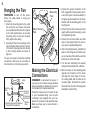
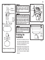
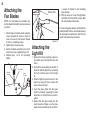
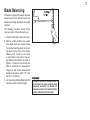
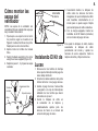
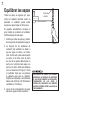
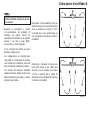
1
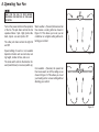
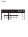
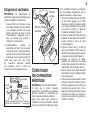
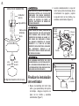
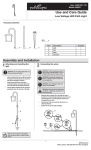
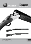
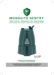
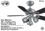
LISTED
52” Novella Ceiling Fan
Owners Manual
Ventilador de Techo de 132.1cm
Manual del Propietario
SKU 355-6791
52” Novella Ceiling Fan
Table of Contents
Safety Rules................................... 1
Unpacking Your Fan...................... 2
Installing Your Fan........................ 3
Operating Your Fan....................... 8
Care of Your Fan............................ 9
Troubleshooting............................ 9
Specifications................................ 10
Warranty Information.................... 11
QUESTIONS, PROBLEMS, MISSING PARTS:
Please do not return to retailer: Call 1-800-749-3267 for any missing
parts or questions regarding installation.
Please reference your SKU (355-6791)
or UPC (082392 636548).
UL Model No. EF600M-52
READ AND SAVE THESE INSTRUCTIONS
1. To reduce the risk of electric shock, ensure electricity
has been turned off at the circuit breaker or fuse box
before beginning.
2. All wiring must be in accordance with the National
Electrical Code ANSI/NFPA 70-1999 and local electrical
codes. Electrical installation should be performed by a
qualified licensed electrician.
3. WARNING: To reduce the risk of fire or electrical shock, do
not use this fan with any solid-state fan speed control device.
4. CAUTION: To reduce the risk of personal injury, use only the
screws provided with the outlet box.
5. The outlet box and support structure must be securely
mounted and capable of reliably supporting a minimum of 35
pounds. Use only UL Listed outlet boxes marked “FOR FAN
SUPPORT.”
6. The fan must be mounted with a minimum of 7 feet
clearance from the trailing edge of the blades to the floor.
7. Do not operate the reverse switch while fan blades are in
motion. Fan must be turned off and blades stopped before
reversing blade direction.
8. Avoid placing objects in the path of the blades.
TO REDUCE THE RISK OF FIRE, ELECTRIC SHOCK OR PERSONAL
INJURY, MOUNT FAN TO OUTLET BOX MARKED “ACCEPTABLE FOR
FAN SUPPORT” WITH THE SCREWS PROVIDED WITH THE OUTLET
BOX. MOST OUTLET BOXES COMMONLY USED FOR THE SUPPORT
OF LIGHTING FIXTURES ARE NOT ACCEPTABLE FOR FAN SUPPORT
AND MAY NEED TO BE REPLACED. CONSULT A QUALIFIED ELECTRICIAN IF IN DOUBT.
Safety Rules 1.
9. To avoid personal injury or damage to the fan and
other items, be cautious when working around or
cleaning the fan.
10.Do not use water or detergents when cleaning the fan or fan
blades. A dry dust cloth or lightly dampened cloth will be suitable for most cleaning.
11.After making electrical connections, spliced conductors
should be turned upward and pushed carefully up into
outlet box. The wires should be spread apart with the
grounded conductor and the equipment-grounding
conductor on one side of the outlet box.
12.Electrical diagrams are for reference only. Light kits that are
not packed with the fan must be UL listed and marked suitable for use with the model fan you are installing. Switches
must be UL general use switches. Refer to the instructions
packaged with the light kits and switches for proper assembly. Use type A 40W MAX. BULBS (supplied).
13.All set screws must be checked and tightened where
necessary before installation.
TO REDUCE THE RISK OF PERSONAL INJURY, DO NOT BEND THE
BLADE BRACKETS (ALSO REFERRED TO AS “FLANGES”) DURING
ASSEMBLY OR AFTER INSTALLATION. DO NOT INSERT OBJECTS IN
THE PATH OF THE BLADES.
2. Unpacking Your Fan
Unpack your fan and check the contents. You should have the following items:
1.
2.
3.
4.
5.
Fan Motor Assembly
Mounting Bracket
Blades (5)
Blade Arms (5)
Motor Housing
6. Light Kit
7. Bulbs (4)
8. Glass Shades (4)
IMPORTANT: THIS PRODUCT AND/OR COMPONENTS ARE COVERED BY
ONE OR MORE OF THE FOLLOWING U.S. PATENTS: 5,947,436; 5,988,580;
5,971,573; 6,010,110; 6,010,306; 6,039,541; 6,046,416 AND OTHER
PATENTS PENDING.
a. Blade Attachment Hardware
(15 screws)
b. Electrical Hardware & Balancing Kit
(Blade Balancing Kit, 3 Plastic Wire
Connectors, 1 Pull Chain for the Fan,
1 Pull Chain for the Light Kit)
If you need an extra switch cup (or cover) for the non-light
option, please call 1-800-283-6513 (M–F 9:00am to 4:40pm EST).
www.gpwarranty.com email:[email protected]
Tools Required
Phillips screw driver, straight slot screw
driver, adjustable wrench, step ladder,
and wire cutters.
Figures 1 and 2 are examples of different
ways to mount the outlet box.
Mounting Options
Outlet Box
If there isn’t an existing outlet box, then read
the following instructions. Disconnect the
power by removing fuses or turning off
circuit breakers.
Figure 3
To hang your fan where there is an existing
fixture but no ceiling joist, you may need an
installation hanger bar as shown in Figure 3.
Secure the outlet box directly to the building
structure. Use the appropriate fasteners
and building materials. The outlet box and
its support must be able to fully support the
moving weight of the fan (at least 35 lbs.)
Do not use plastic outlet boxes.
TO REDUCE THE RISK OF FIRE, ELECTRIC
SHOCK OR PERSONAL INJURY, MOUNT
FAN ONLY TO AN OUTLET BOX MARKED
ACCEPTABLE FOR FAN SUPPORT AND
USE THE MOUNTING SCREWS PROVIDED
WITH THE OUTLET BOX. OUTLET BOXES
COMMONLY USED FOR THE SUPPORT
OF LIGHTING FIXTURES MAY NOT BE
ACCEPTABLE FOR FAN SUPPORT AND
MAY NEED TO BE REPLACED. CONSULT A
QUALIFIED ELECTRICIAN IF IN DOUBT.
Installing Your Fan 3.
Figure 1
Outlet Box
Figure 2
4.
Hanging the Fan
REMEMBER to turn off the power.
Follow the steps below to hang your
fan properly.
1. Attach the mounting plate to the outlet
box using the two screws and washers provided with the outlet box (Figure
5). For best performance, be sure the
mounting plate is level and secured
firmly against the ceiling.
2. Carefully lift the motor assembly (without the blades) and insert the T section
of the motor housing plate into the slot
in the mounting bracket as shown in
Figure 6.
You are now ready to make the electrical
connections. Wire your fan according to
the instructions in the following section.
Outlet
Box
Mounting
Plate
Mounting Screws And Washers
(Provided With Outlet Box)
Leveling
Washer
(If Required)
Not Included
Isolation
Pads
Figure 4
Mounting
Plate
Motor Housing
Plate
Figure 5
Making the Electrical
Connections
REMEMBER to disconnect the power. If
you feel you do not have enough electrical
wiring knowledge or experience, have your
fan installed by a licensed electrician.
Follow the steps below to connect the fan
to your household wiring. Use the wire
connecting nuts supplied with your fan.
Secure the connectors with electrical tape.
Make sure there are no loose strands or
connections.
1. Connect the ground conductor of the
120v supply (this may be a bare wire or
a wire with green colored insulation) to
the green ground leads from the motor
bracket and the mounting plate of the
fan (Figure 6).
2. Connect the fan motor white wire to the
supply white (neutral) wire using a wire
nut supplied (Figure 6).
3. Connect the fan motor black and blue
wires to the supply black (hot) wire using a wire nut supplied (Figure 6).
4. After connecting the wires, spread them
apart so that the green and white wires
are on one side of the outlet box and the
black wire is on the other side.
5. Turn the wire connecting nuts upward
and push the wiring into the outlet box.
6. Remove screws on the mounting plate
opposite the T-section. Lift the motor
and align the screw holes of the motor housing plate with the holes in the
mounting plate. Re-install the screws
removed from the motor housing plate
and tighten screws firmly.
5.
BLACK
WHITE
SUPPLY CIRCUIT
Ground
Conductor
TO REDUCE RISK OF FIRE OR ELECTRIC
SHOCK, DO NOT USE A SOLID STATE
SPEED CONTROL WITH THIS FAN. IT WILL
PERMANENTLY DAMAGE THE ELECTRONIC
CIRCUITRY.
Motor Housing
Plate
Hanger
Bracket
Washers
BLUE
BLACK
WHITE
GREEN
Outlet Box
Green
Ground
Lead
EACH WIRE NUT (WIRE CONNECTOR) SUPPLIED WITH THIS FAN IS DESIGNED TO ACCEPT
UP TO ONE 12 GAUGE HOUSE WIRE AND TWO
WIRES FROM THIS FAN. IF YOU HAVE LARGER
THAN 12 GAUGE HOUSE WIRING OR MORE
THAN ONE HOUSE WIRE TO CONNECT TO THE
FAN WIRING, CONSULT AN ELECTRICIAN FOR
THE PROPER SIZE WIRE NUTS TO USE.
Screws
Motor
Figure 7
ELECTRICAL DIAGRAMS ARE FOR REFERENCE ONLY. OPTIONAL USE OF ANY LIGHT KIT
SHALL BE UL LISTED AND MARKED SUITABLE
FOR USE WITH THIS FAN.
BLUE
BLACK
Finishing the
Installation
WHITE
WHITE
Diagram indicates light kit wiring.
Figure 6
1. Swing the motor assembly up into position under the mounting bracket. Secure
the bracket to the plate with the screws
and washers provided (Figure 7).
2. Carefully lift the motor housing onto the
mounting plate, properly align the holes
and tighten the motor housing with
the four screws and washers supplied
(Figure 8).
Screws
And
Washers
Figure 8
6.
Attaching the
Fan Blades
Rubber Pad
NOTE: Your fan blades are reversible. Select the blade finish which best accentuates
you decor.
1. Attach blade to blade bracket using the
screws provided as shown in figure 9.
Insert a screw into the bracket. Repeat
for the two remaining screws.
2. Tighten each screw securely.
3. Fasten the blade assembly to the motor
using the screws supplied (Figure 10).
4. Repeat steps 1-3 for the remaining
blades.
Fiber Washer
Fan
Blade
Mounting
Screw
Blade
Bracket
Figure 9
Figure 10
Attaching the
Light Kit
1. Remove the three mounting screws on
the switch cap of the light kit below the
motor.
2. Connect the wires exiting the bottom of
the motor with the light kit by connecting
the motor with the wires from the light
kit.
3. Slide the light kit up and secure it to the
switch cup using the three screws that
were removed in step 1.
4. Insert the glass shade into the glass
holder by carefully squeezing the steel
tensioners on the light fixture socket together.
5. Gently slide the glass shade over the
steel tensioners. Make sure the glass
shade is fully inserted into the socket for
a secure fit. Repeat for the remaining
glass shades.
6. With the power off, insert the light bulbs
(included) into the light kit sockets. Max
40 watts medium base bulbs.
To remove the glass shades, gently slide the
shade partially from the socket and squeeze
the exposed steel tensioners. Remove the
shade and release the tensioners.
7.
Blade Balancing
All blades are grouped by weight. Because
natural woods vary in density, the fan may
wobble even though the blades are weight
matched.
The following procedure should correct
most fan wobble. Check after each step.
1. Check that all blade screws are secure.
2. Most fan wobble problems are caused
when blade levels are unequal. Check
this level by selecting a point on the ceiling above the tip of one of the blades.
Measure from a point on the center
of each blade to the point on the ceiling. Measure this distance as shown in
Figure 11. Rotate the fan until the next
blade is positioned for measurement.
Repeat for each blade. Measurement
deviations should be within 1/8”. Run
the fan for 10 minutes.
3. Use the enclosed Blade Balancing Kit if
the blade wobble is still noticeable.
Figure 11
TO REDUCE THE RISK OF PERSONAL INJURY,
DO NOT BEND THE BLADE HOLDERS WHILE
INSTALLING, BALANCING THE BLADES, OR
CLEANING THE FAN. DO NOT INSERT FOREIGN
OBJECTS BETWEEN ROTATING BLADES.
8. Operating Your Fan
WAIT FOR THE FAN TO STOP BEFORE
REVERSING THE DIRECTION OF THE BLADE
ROTATION.
Turn on the power and check the operation
of the fan. The pull chain controls the fan
speed as follows: 1 pull - High, 2 pulls - Medium, 3 pulls - Low and 4 pulls - Off.
The other pull chain controls the light On
and Off.
Warm weather - (Forward) A downward air
flow creates a cooling effect as shown in
Figure 12. This allows you to set your air
conditioner on a higher setting without affecting your comfort.
Speed settings for warm or cool weather
depend on factors such as room size, ceiling height, number of fans, and so on.
The slide switch controls the direction forward (switch down) or reverse (switch up).
Figure 12
Cool weather - (Reverse) An upward air
flow moves warm air off the ceiling are as
shown in Figure 13. This allows you to set
your heating unit on a lower setting without
affecting your comfort.
Figure 13
Care of Your Fan
Here are some suggestions to help you
maintain your fan.
1. Because of the fan’s natural movement,
some connections may become loose.
Check the support connections,
brackets, and blade attachments
twice a year. Make sure they are secure. (It is not necessary to remove
the fan from the ceiling.)
2. Clean your fan periodically to help
maintain its new appearance over the
years. Do not use water when cleaning, this could damage the motor, or
the wood or possibly cause an electrical shock. Use only a soft brush or lintfree cloth to avoid scratching the finish.
The plating is sealed with a lacquer to
minimize discoloration or tarnishing.
Warning - Make sure the power is off
before cleaning your fan.
3. You can apply a light coat of furniture
polish to the wood for additional protection and enhanced beauty. Cover small
scratches with a light application of
shoe polish.
4. There is no need to oil your fan.
The motor has permanently lubricated
sealed ball bearings.
Troubleshooting
ProblemSolution
Fan will not start 1. Check the main and branch circuit fuses or breakers
2. CAUTION: Make sure main power is off. Check the line wire
connections to the fan and switch wire connections in the switch
housing.
Fan sounds noisy
1. Make sure all motor housing screws are snug.
2. Make sure the screws that attach the fan blade bracket to the
motor hub are tight.
3. Make sure the wire nut connections are not rattling against each
other or the interior wall of the switch housing.
CAUTION: Make sure the power is off.
4. Allow a 24-hour “breaking in” period. Most noises associated with
a new fan disappear during this time.
5. If using the Ceiling Fan light kit, make sure the tensioners or
screws securing the glassware are tight. Check that the light bulb
is also secure.
6. Make sure the canopy is a short distance from the ceiling.
It should not touch the ceiling.
7. Make sure your outlet box is secure and rubber isolator pads
were used between the mounting bracket and outlet box.
8. Make sure pull chains are not vibrating against glass or housing.
MAKE SURE THE POWER IS OFF AT THE ELECTRICAL PANEL BOX BEFORE YOU ATTEMPT TO MAKE ANY REPAIRS. REFER TO THE SECTION,
“MAKING ELECTRICAL CONNECTIONS.”
9.
10. Specifications
FAN SIZE
52”
SPEED
VOLTS
AMPS
WATTS
RPM
CFM
Low
120
0.26
13
70
1820
Med
120
0.39
30
120
3150
High
120
0.52
60
165
4740
NET
WEIGHT
GROSS
WEIGHT
CUBE
FEET
18.48
LBS
20.9
LBS
1.77
These are approximate measures. They do not include Amps and Wattage used by the light kit.
Limited Lifetime Warranty
Lifetime Warranty on Motor
Warranty Information 11.
The manufacturer warrants the fan motor to be free from defects in workmanship and
material present at time of the shipment from the factory for a lifetime after the date of
purchase by the original purchaser. The manufacturer also warrants that all other fan parts,
excluding any glass or acrylic blades, to be free from defects in workmanship and material
IMPORTANT NOTE:
at the time of shipment from the factory for a period of one year after the date of purchase
To ensure warranty service, if ever
by the original purchaser. We agree to correct such defects without charge or at our option
necessary, please register your fan at:
replace with a comparable or superior model if the product is returned to the manufacturer.
gpwarranty.com
To obtain warranty service, you must present a copy of the receipt as proof of purchase.
All costs of removing and reinstalling the product are your responsibility. Damage to any
You must present a copy of the original
part such as by accident or misuse or improper installation or by affixing any accessories,
is not covered by this warranty. Because of varying climatic conditions, this warranty does purchase receipt to obtain warranty service.
not cover any changes in plated finishes, including rusting, pitting, corroding, tarnishing or
peeling. Brass finishes of this type give their longest useful life when protected from varying G.P. WARRANTY SERVICE CENTER, INC.
weather conditions. A certain amount of “wobble” is normal and should not be considered
WARRANTY SECTION
a defect. Servicing performed by unauthorized persons shall render the warranty invalid.
1951 N.W. 22nd STREET
There is no other express warranty. The manufacturer hereby disclaims any and all warFORT LAUDERDALE, FLORIDA 33311
ranties, including but not limited to, those of merchantability and fitness for a particular
purpose to the extent permitted by law. The duration of any implied warranty which cannot be disclaimed is limited to the time period as specified in the express warranty. Some
states do not allow limitation on how long an implied warranty lasts, so the above limitation
may not apply to you. The manufacturer shall not be liable for incidental, consequential, or
special damages arising out of or in connection with product use or performance except as
may otherwise be accorded by law. Some states do not allow the exclusion of incidental
or consequential damages, so the above exclusion or limitation may not apply to you. This
warranty gives specific legal rights, and you may also have other rights which vary form
state to state. This warranty supersedes all prior warranties. Shipping costs for any return
of product as part of a claim on the warranty must be paid by the customer.
Novella de 52” Ventilador de techo
Índice
Normas de seguridad...................... 1
Cómo desempacar el ventilador.... 2
Cómo instalar el ventilador............ 3
Cómo operar el ventilador.............. 8
Cuidado del ventilador.................... 9
Solución de problemas................... 9
Especificaciones............................. 10
Información de garantía.................. 11
¿PREGUNTAS, PROBLEMAS O PIEZAS FALTANTES?
Por favor, no devuelva al vendedor minorista: Llame a 1-800-749-3267 para cubrir las
partes faltantes o cuestiones relacionadas con la instalación.
Por favor usa como referencia el Nº de SKU (355-6791)
o UPC (082392 636548).
Número de Modelo UL EF600M-52
1. Normas de seguridad
LEE LAS INSTRUCCIONES Y GUÁRDALAS
1. Para disminuir el riesgo de descarga eléctrica, asegúrate
de que la electricidad ha sido apagada en el cortacircuitos
o la caja de fusibles antes de comenzar la instalación.
2. Todo el cableado debe cumplir con el Código Nacional de
Electricidad ANSI/NFPA 70-1999 y con los códigos locales de
electricidad. La instalación eléctrica debe ser hecha por un
electricista certificado y calificado.
3. ADVERTENCIA:Para disminuir el riesgo de incendio o
descarga eléctrica este ventilador sólo debe ser usado con un
control de velocidad con el N.o de pieza FAN-HD, fabricado por
Chia Wei Electric Co., Ltd.
4. PRECAUCIÓN: Para reducir el riesgo de lesiones físicas, usa
sólo los tornillos provistos con la caja eléctrica.
5. La caja eléctrica y estructura de soporte deben montarse de
forma segura y tener capacidad para sostener de manera
confiable un mínimo de 35 libras. Usa solamente cajas
eléctricas aprobadas por UL marcadas como “PARA SOPORTE
DE VENTILADOR”.
6. El ventilador debe ir montado con un mínimo de 7 pies de
separación entre el borde trasero de las aspas y el piso.
7. No operar el interruptor de reversa mientras las aspas del
ventilador estén en movimiento. El ventilador debe estar
PARA REDUCIR EL RIESGO DE INCENDIO, DESCARGA ELÉCTRICA
O LESIONES PERSONALES, MONTA EL VENTILADOR SOBRE UNA
CAJA ELÉCTRICA MARCADA COMO “APROBADA COMO SOPORTE
DE VENTILADOR” Y USA LOS TORNILLOS DE MONTAJE QUE
VIENEN CON LA MISMA. LAS CAJAS ELÉCTRICAS UTILIZADAS
COMÚNMENTE PARA EL SOPORTE DE ARTÍCULOS DE ILUMINACIÓN
PUEDEN NO SERVIR COMO SOPORTE DE VENTILADOR, Y TAL VEZ
DEBAN REEMPLAZARSE. EN CASO DE DUDA, CONSULTA A UN
ELECTRICISTA CALIFICADO.
apagado y las aspas detenidas antes de invertir la dirección
del movimiento.
8. Evita colocar objetos en la trayectoria de las aspas.
9. Para evitar lesiones, o daños al ventilador y otros objetos; ten
cuidado al trabajar cerca del ventilador o al limpiarlo.
10.No usar agua o detergentes para limpiar el ventilador o las
aspas. En general a la hora de limpiar, bastará con usar un
paño seco o ligeramente humedecido.
11.Después de concluir con las conexiones eléctricas, debes
voltear los conductores empalmados hacia arriba y empujarlos
con cuidado hacia dentro de la caja eléctrica. Los cables deben
estar separados, con el cable a tierra y el conductor a tierra del
equipo hacia uno de los lados de la caja eléctrica.
12.Los diagramas eléctricos son sólo una referencia. Los kits de
luces no empaquetados con el ventilador deben estar aprobados
por UL y marcados como apropiados para ser usados con el
modelo de ventilador a instalar. Los interruptores deberán
estar clasificados por el UL como de Uso General. Consulta
las instrucciones adjuntas a los kits de luces e interruptores
para obtener información sobre el ensamblaje adecuado. Usa
bombillas de tipo A de 40 vatios máximo (incluidas).
13.Todos los tornillos colocados se deben verificar y ajustar
donde sea necesario antes de la instalación.
PARA REDUCIR EL RIESGO DE LESIONES PERSONALES, NO DOBLAR
LOS BRAZOS DE LAS ASPAS (TAMBIÉN LLAMADOS “REBORDES”)
DURANTE O DESPUÉS DE LA INSTALACIÓN. EVITA COLOCAR
OBJETOS EN LA TRAYECTORIA DE LAS ASPAS.
Cómo desempacar el ventilador 2.
Desempaca tu ventilador y revisa el contenido. Deberá tener las siguientes piezas:
1.
2.
3.
4.
5.
Ensamblado del motor
Soporte de montaje
Aspas (5)
Soportes del aspa (5)
Carcasa del motor
6. Kit de Luces
7. Bombillas (4)
8. Pantallas de vidrio (4)
IMPORTANTE: ESTE PRODUCTO Y/O SUS COMPONENTES ESTÁN
PROTEGIDOS POR UNA O MÁS DE LAS SIGUIENTES PATENTES DE
EE.UU.: 5,947,436; 5,988,580; 5,971,573; 6,010,110; 6,010,306; 6,039,541;
6,046,416 Y OTRAS PATENTES PENDIENTES.
a. Herrajes de montaje de aspas
(15 tornillos)
b. Herrajes eléctricos
y kit de compensación
(Kit de compensación de aspas, 3
conectores plásticos de cables, 1
cadena del ventilador para halar, 1
cadena del kit de luces para halar)
Si usted necesita una caja del interruptor adicional para la
opción de la no-luz, llame por favor al 1-800-283-6513 (lunes
a viernes de 9:00 a 4:40 P.M. EST).
www.gpwarranty.com email:[email protected]
3. Cómo instalar el ventilador
Herramientas
necesarias
Destornillador
Phillips,
destornillador
plano, llave ajustable, escalera de tijera y
cortacables.
Las figuras 1, 2 y 3 son ejemplos de
diferentes formas de montar la caja
eléctrica.
Opciones de montaje
Caja eléctrica
Figura 3
Si no hay una caja de montaje existente,
entonces lee las siguientes instrucciones.
Desconecta la energía retirando los
fusibles o apagando los cortacircuitos.
Para colgar tu ventilador donde haya
una lámpara pero ninguna viga de techo,
tal vez necesites una barra colgante de
instalación como se muestra en la Figura 3.
Asegura la caja eléctrica directamente a la
estructura del edificio. Usa sujetadores y
materiales de construcción apropiados. La
caja eléctrica y su soporte deben sostener
completamente el peso en movimiento
del ventilador (al menos 35 libras).
No uses cajas eléctricas de plástico.
PARA REDUCIR EL RIESGO DE INCENDIO,
DESCARGA ELÉCTRICA O
LESIONES
PERSONALES, MONTA EL VENTILADOR
SÓLO SOBRE UNA CAJA ELÉCTRICA
MARCADA COMO “APROBADA COMO
SOPORTE DE VENTILADOR” Y USA
LOS TORNILLOS DE MONTAJE QUE
VIENEN CON LA MISMA. LAS CAJAS
ELÉCTRICAS UTILIZADAS COMÚNMENTE
PARA EL SOPORTE DE ARTÍCULOS DE
ILUMINACIÓN PUEDEN NO SERVIR COMO
SOPORTE DE VENTILADOR, Y TAL VEZ
DEBAN REEMPLAZARSE. EN CASO DE
DUDA, CONSULTA A UN ELECTRICISTA
CALIFICADO.
Caja eléctrica
Figura 1
Caja eléctrica
Figura 2
4.
Colgando el ventilador
Placa de
montaje
RECUERDE:
De
desconectar
la
electricidad. Siga los pasos Indicados para
colgar su ventilador correctamente.
1. Anexe el Plato de montaje a la caja
de montaje utilizando los dos tornillos
y las arandelas provistas con la caja
eléctrica (vea figura 5). Para un mejor
funcionamiento, asegúrese que el
plato de montaje este nivelado y
firmemente contra el techo.
2. Cuidadosamente
levante
el
ensamblaje del motor (sin las aspas)
e inserte la sección T de la placa de la
caja del motor en la ranura del soporte
de montaje como lo muestra la figura 6.
Usted esta ahora listo para hacer
las conexiones eléctricas. Realice
las conexiones como lo indica las
instrucciones en la siguiente sección.
Caja eléctrica
Placa de
montaje
Arandelas
niveladoras
(Si es necesario)
No Incluido
Tornillos y arandelas de montaje Almohadilla
de Aislamiento
(Incluido en la caja eléctrica)
Figura 4
Plato de montaje
del Motor
Cómo hacer
las conexiones
eléctricas
Figura 5
RECUERDA desconectar la electricidad.
Si crees que no tienes suficiente
experiencia o conocimientos en cableado
eléctrico, contrata a un electricista con
licencia para que instale el ventilador.
Sigue estos pasos para conectar tu
ventilador a tu circuito doméstico. Usa las
tuercas de conexión de cables que vienen
con tu ventilador. Asegura los conectores
con cinta aislante. Asegúrate de que no
existan conexiones o cables sueltos.
1. Conecta el conductor a tierra del cable
de 120 voltios (puede ser un cable
desnudo o un cable con aislante verde)
a los cables terminales a tierra verdes
del soporte del motor y la placa de
montaje del ventilador (Figura 6).
2. Conecta el cable blanco del motor del
ventilador al cable blanco de suministro
(neutro) usando la tuerca de cable
provista (Figura 6).
3. Conecta el cable negro y el azul del
motor del ventilador al cable negro de
suministro de energía (positivo) usando
la tuerca de cable incluida (Figura 6).
4. Después de conectar los cables,
sepáralos de manera que los cables
verde y blanco queden de un lado de la
caja eléctrica y el cable negro del otro.
5. Gira las tuercas de conexión del cable
hacia arriba y coloca el cableado dentro
de la caja eléctrica.
6. Quite los tornillos de la placa de montaje
frente a la T-sección. Levante el motor y
alinear los agujeros de los tornillos de
la placa de la caja del motor con los
agujeros en la placa de montaje. Vuelva
a instalar los tornillos que quitó de la
placa de la caja del motor y apriete los
tornillos con firmeza.
5.
NEGRO
BLANCO
CIRCUITO DE SUMINISTRO
Conductor
a tierra
AZUL
NEGRO
VERDE
BLANCO
AZUL
NEGRO
Caja eléctrica
Cable verde
terminal a
tierra
PARA REDUCIR EL RIESGO DE INCENDIO O
DESCARGA ELÉCTRICA, NO UTILICES ESTE
VENTILADOR CON NINGÚN DISPOSITIVO
DE CONTROL DE VELOCIDAD DE ESTADO
SÓLIDO, DE MONTAJE EN PARED. EL
CIRCUITO ELECTRÓNICO SE DAÑARÁ EN
FORMA PERMANENTE.
CADA TUERCA DEL CABLE (CONECTOR DE
CABLE) PROVISTA CON ESTE VENTILADOR
ESTÁ DISEÑADA PARA ACEPTAR CABLES
DOMÉSTICOS DE MÁXIMO UN CALIBRE 12 Y
DOS CABLES DEL VENTILADOR. SI TIENES
UN CABLEADO DOMÉSTICO DE CALIBRE
SUPERIOR A 12, O MÁS DE UN CABLE
DOMÉSTICO PARA CONECTAR EL CABLEADO
DEL
VENTILADOR,
CONSULTA
A
UN
ELECTRICISTA PARA EL TAMAÑO ADECUADO
DE TUERCAS DE CABLE.
LOS DIAGRAMAS ELÉCTRICOS SON SÓLO
UNA REFERENCIA. EL USO OPCIONAL DE KITS
DE LUCES DEBE ESTAR APROBADO POR UL
Y ESTARÁ MARCADO COMO ADECUADO PARA
SER USADO EN ESTE VENTILADOR.
BLANCO
BLANCO
El diagrama muestra un kit de luces.
Figura 6
Finalizar la instalación
del ventilador
1. Mueva el ensamblaje del motor hacia
arriba y que quede debajo del soporte
de montaje. Asegure el soporte a la
placa con los tornillos y arandelas
suministradas (Figura 7).
2. Levante cuidadosamente la caja del
motor hacia el plato de montaje, alinee
correctamente los agujeros y apriete
la caja del motor con los tornillos y las
arandelas suministradas (Figura 8).
Plato de
montaje
del Motor
Placa de
montaje
Arandelas
Tornillos
Motor
Figura 7
Tornillos
y arandelas
Figura 8
Cómo montar las
aspas del
ventilador
NOTA: Las aspas de tu ventilador son
reversibles. Elige el acabado del aspa que
mejor resalte tu decoración.
1. Fija el aspa a su soporte con los tornillos provistos según se muestra en la
Figura 9. Inserta el tornillo en el soporte.
Repite para los otros dos tornillos.
2. Aprieta todos los tornillos de manera
firme.
3. Fasten the blade assembly to the motor
using the screws supplied (Figura 10).
4. Repite los pasos 1, 2 y 3 para las aspas
restantes.
Tornillo de
montaje
Arandelas de fibra
Soporte de aspa
Aspa
Figura 9
Almohadilla
de Goma
Figura 10
Instalando El Kit de
Luces
1. Remueva los tres tornillos de montaje
de la caja de interruptores del juego de
luces debajo del motor.
2. Conecte los cables salientes de la parte
Inferior del motor con el juego de luces.
3. deslice el juego de luces hacia arriba
y asegúrelo a la caja de interruptores
utilizando los tres tornillos que fueron
removidos en el paso 1.
4. Inserte la lámpara de vidrio en
el sostenedor de la lámpara y
cuidadosamente apriete junto los
tensores de hierro en el zócalo del
accesorio del juego de luces.
5. Suavemente deslice la lámpara de
vidrio sobre los tensores de hierro.
Asegúrese de que la lámpara de vidrio
este insertada correctamente en el
zócalo para un ajuste seguro. Repita
para las lámparas de vidrios restantes.
6. Con la energía apagada, inserte las
bombillas de 40 W máximo (incluidas)
en los zócalos del juego de luces.
Para quitar la lámpara de vidrio, deslice
suavemente la lámpara de vidrio
parcialmente del zócalo y apriete los
tensores de acero expuestos. Quite la
lámpara de vidrio y afloje los tensores.
6.
7.
Equilibrar las aspas
Todas las aspas se agrupan por peso.
Como las maderas naturales varían en
densidad, el ventilador puede oscilar
aunque las aspas tengan el mismo peso.
Punto en
el techo
El siguiente procedimiento corregirá en
gran medida la oscilación del ventilador.
Verifica después de cada paso.
1. Verifica que todas las aspas y tornillos
de los soportes de aspas estén seguros.
2. La mayoría de los problemas de
oscilación del ventilador se deben a
que las aspas no están a un mismo
nivel. Verifica este nivel seleccionando
un punto en el techo sobre la punta
de una de las aspas. Mide desde un
punto en el centro de cada aspa a un
punto en el techo. Mide esta distancia
como se muestra en la Figura 11. Rota
el ventilador hasta que se posicione
la siguiente aspa para su medición.
Repite para cada aspa. Las mediciones
deben estar dentro de 1/8”. Enciende el
ventilador por 10 minutos.
3. Usa el kit de compensación de aspas
adjunto si sigues notando oscilación.
Figura 11
PARA REDUCIR EL RIESGO DE LESIONES
PERSONALES, NO DOBLAR LOS SOPORTES
DE LAS ASPAS DURANTE LA INSTALACIÓN,
COMPENSACIÓN
DE
LAS
ASPAS
O
LIMPIEZA DEL VENTILADOR. NO INSERTES
OBJETOS EXTRAÑOS ENTRE LAS ASPAS EN
FUNCIONAMIENTO.
Cómo operar el ventilador 8.
ESPERA A QUE SE DETENGA EL VENTILADOR
ANTES DE INVERTIR LA DIRECCIÓN DE GIRO
DE LAS ASPAS.
Enciende la electricidad y verifica
el funcionamiento del ventilador. El
interruptor de cadena controla las
velocidades del ventilador de la siguiente
manera: 1 vez: Alto, 2 veces: Medio,
3 veces: Bajo y 4 veces: Apagado.
Clima cálido - (Hacia adelante) Un flujo de
aire hacia abajo crea un efecto refrescante
como se muestra en la Figura 12. Esto
te permite fijar tu aire acondicionado en
una configuración más alta sin afectar tu
comodidad.
Figura 12
El otro interruptor de cadena sirve para
Encender y Apagar la luz.
Las configuraciones de velocidad para
clima cálido o frío dependen de factores
como tamaño de la habitación, altura del
techo, cantidad de ventiladores y demás.
Los controles del interruptor deslizable
cambian la dirección del flujo de aire: hacia
delante (interruptor para abajo) o reversa
(interruptor para arriba).
Clima fresco - (Reversa) Un flujo de aire
hacia arriba mueve el aire cálido lejos
del techo como se muestra en la Figura
13. Esto te permite fijar tu unidad de
calefacción en una configuración más baja
sin afectar tu comodidad.
Figura 13
9.
Cuidado del
ventilador
Aquí tienes algunas sugerencias para el
mantenimiento de tu ventilador.
1. Debido al movimiento natural del
ventilador, algunas conexiones pueden
aflojarse. Revisa las conexiones
de soporte, soportes y accesorios
de aspas dos veces al año. Verifica
que estén seguros. (No es necesario
desmontar el ventilador del techo).
2. Limpia tu ventilador con frecuencia,
para que luzca como nuevo a pesar
de los años. No uses agua al limpiar,
esto puede dañar el motor o la madera,
o causar descargas eléctricas. Usa
solamente un cepillo suave o trapo sin
pelusas para evitar arañar el acabado. El
revestimiento está sellado con laca para
minimizar la decoloración u opacidad.
Advertencia: Asegúrate de que la
corriente esté apagada antes de
limpiar el ventilador.
3. Puedes aplicar una fina capa de
pulimento para muebles a la madera
para una mayor protección y belleza.
Cubre los arañazos pequeños con
una leve aplicación de lustrador para
calzado.
4. Tu ventilador no necesita lubricación.
El motor tiene cojinetes de bola sellados
permanentemente lubricados.
Solución de problemas
ProblemSolución
El ventilador no
enciende
1. Verifica fusibles o disyuntores principales y secundarios.
2. PRECAUCIÓN: Asegúrate de que esté desactivada la
electricidad principal. Verifica conexiones de cables en línea
al ventilador y conexiones de cables del interruptor en la caja de
interruptores.
El ventilador hace 1. Asegúrate de que los tornillos de la carcasa del motor estén
ajustados.
ruido
2. Asegúrate de que los tornillos que unen el soporte de aspa al
cuerpo del motor están bien ajustados.
3. Asegúrate de que las conexiones de tuerca de cable no choquen
unas con otras o con la pared interior de la caja del interruptor.
PRECAUCIÓN: Asegúrate de que esté desconectada la
electricidad.
4. Permite un período de 24 horas de “adaptación”. La mayoría de
los ruidos asociados con un nuevo ventilador desaparecen en
ese período.
5. Si usas el kit de luces de ventilador de techo, asegúrate de
que los tensores o los tornillos que sujetan el vidrio estén bien
ajustados. Verifica que la bombilla esté bien asegurada.
6. Asegúrate de que la cubierta esté a corta distancia del techo.
No debe tocar el techo.
7. Asegúrate de que tu caja eléctrica esté bien segura y las
almohadillas aislantes de goma se hayan instalado entre el
soporte de montaje y la caja eléctrica.
8. Asegúrate de que las cadenas para halar no choquen contra el
vidrio o la carcasa.
ASEGÚRATE DE QUE ESTÉ DESCONECTADA LA ELECTRICIDAD EN EL
PANEL DE ELECTRICIDAD ANTES DE INTENTAR HACER REPARACIONES.
CONSULTA LA SECCIÓN “CÓMO HACER LAS CONEXIONES ELÉCTRICAS”.
Especificaciones 10.
TAMAÑO
52”
VELOCIDAD
VOLTIOS
AMPERIOS
VATIOS
RPM
PIES CÚB.
X MIN.
Baja
120
0.26
13
70
1820
Media
120
0.39
30
120
3150
Alta
120
0.52
60
165
4740
PESO
NETO
PESO
BRUTO
PIES
CÚB.
18.48
LBS
20.9
LBS
1.77
Estas son las medidas aproximadas. No incluyen ni el amperaje ni el vataje consumido por el kit de luces.
11.
Garantía limitada de por vida
Garantía de por vida para el motor
El fabricante garantiza de por vida, a partir de la fecha de compra por el comprador original,
que el motor del ventilador no presenta defectos de fabricación ni de material desde la
fecha de salida de la fábrica. El fabricante también garantiza por un período de un año,
a partir de la fecha de compra por el comprador original, que todas las demás piezas del
ventilador, sin incluir ninguna aspa de vidrio o acrílico, no presentarán ningún defecto de
fabricación o de material desde el momento de su salida de la fábrica. Acordamos reparar
todos los defectos del tipo antes mencionado, sin cargo alguno, o a nuestra discreción,
reemplazar el producto por un modelo de calidad comparable o superior si el producto se
NOTA IMPORTANTE:
devuelve a el fabricante. Para obtener una garantía de servicio usted debe presentar una
Para asegurar la garantía de servicio,
copia del recibo como comprobante de compra. Todos los costos de retiro y reinstalación
si es necesario, registre su ventilador en:
del producto son su responsabilidad. Daños a cualquiera de las piezas como resultado de
gpwarranty.com
accidentes, instalación o uso incorrectos o debidos a la instalación de cualquier accesorio,
no están cubiertos bajo esta garantía. Debido a que las condiciones climáticas pueden
Usted debe presentar una copia del
variar, esta garantía no cubre ningún cambio en el acabado revestido, incluyendo óxido,
recibo de compra original para obtener
picaduras, corrosión, manchas o descascaramiento. Los acabados de bronce de este tipo
garantía de servicio.
tienen una vida útil más prolongada cuando se protegen de las condiciones climáticas
cambiantes. Es normal cierta “oscilación” y no se considerará una falla. Cualquier servicio
técnico conducido por personas no autorizadas anulará la garantía. No hay ninguna otra G.P. WARRANTY SERVICE CENTER, INC.
garantía expresa. Mediante la presente el fabricante se exime de cualquier garantía,
WARRANTY SECTION
incluyendo pero sin limitarse a aquellas de comercialización e idoneidad para un fin
1951 N.W. 22nd STREET
particular, de acuerdo a lo contemplado por la ley. La duración de cualquier garantía
FORT LAUDERDALE, FLORIDA 33311
implícita que no se pueda eximir, está limitada al período de tiempo especificado en la
garantía explícita. Algunos estados no permiten limitaciones en la duración de la garantía,
por consiguiente la limitación anterior puede no aplicarse a usted. El fabricante no será
responsable por daños directos, indirectos o especiales que resulten o deriven del uso o
rendimiento del producto excepto en casos en que lo estipule la ley. Algunos estados no
permiten la exclusión o limitación de daños directos o indirectos, por lo que la limitación
o exclusión anterior podría no aplicarse a usted. Esta garantía le otorga derechos legales
específicos pero es posible que también tenga otros derechos que varían de un estado
a otro. Esta garantía sustituye todas las garantías anteriores. Los costos de envío de
cualquier devolución de productos hecha como parte de una reclamación de garantía
deben ser pagados por el cliente.