1
Istruzione d'uso
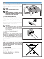
Montaggio
Manutenzione
GUIDA TECNICA
Istructions for Use
Assembly
Maintenance
User's Manual - Technische Anleitung
Guide Technique - Manual Técnico
Bedienungsanweisung
Montage
Wartung
Utilisation
Assemblage
Entretien
Manual para el uso,
ensamblaje y
mantenimiento
Gelateria
QUAD - MAXYMA
QMGE 0410
ICE-CREAM DISPLAY UNIT - EISVITRINE
VITRINE A GLACES - VITRINA HELADERÍA
SOMMARIO / INDEX / INHALTS-VERZEICHNIS / SOMMAIRE / SOMARIO
ITALIANO ............................................................3
ENGLISH.......................................................... 30
DEUTCH........................................................... 57
FRANÇAIS ........................................................84
ESPAÑOL ...................................................... 111
I
Sommario
INTRODUZIONE
4
1 SPECIFICHE TECNICHE
1.1 DESCRIZIONE DELLA VETRINA
1.2 MODELLI
1.3 IDENTIFICAZIONE
1.4 NORME APPLICATE
1.5 CARATTERISTICHE TECNICHE
1.6 DIMENSIONI DI INGOMBRO E PESI
5
5
6
6
6
6
8
2 INSTALLAZIONE
2.1 TRASPORTO
2.2 SOLLEVAMENTO E MOVIMENTAZIONE
2.3 POSIZIONAMENTO
2.4 SPECIFICHE AMBIENTALI
2.5 MONTAGGIO PIEDINI
2.6 MONTAGGIO RUOTE (dove previsto).
2.7 CANALIZZAZIONI (dove previsto)
2.8 MONTAGGIO CAPPELLO IN VETRO
2.9 MONTAGGIO FIANCHI TERMINALI
2.10 COLLEGAMENTO ELETTRICO
2.11 NOTE AMBIENTALI
2.12 ACCESSORI
9
9
9
9
9
10
11
12
15
16
18
18
18
3 FUNZIONAMENTO
3.1 OPERAZIONI PRELIMINARI DI CONTROLLO
3.2 AVVIAMENTO
3.3 REGOLAZIONE DELLA TEMPERATURA
3.4 SBRINAMENTO AUTOMATICO A GAS CALDO
3.5 SBRINAMENTO MANUALE
3.6 FERMATA
3.7 Opzione BT-TN
3.8 COMMUTAZIONE GELATERIA-PASTICCERIA
3.9 APERTURA CAPPELLO IN VETRO (versione VBD)
3.10 APERTURA VETRO ANTERIORE (versione VAD)
19
19
19
19
20
20
20
20
20
21
21
4 MANUTENZIONE ORDINARIA
4.1 OPERAZIONI PRELIMINARI DI SICUREZZA
4.2 PULIZIA CONDENSATORE
4.3 PULIZIA INTERNO ED ESTERNO DELLA VETRINA
4.4 PULIZIA VASCHETTA RACCOGLICONDENSA (OPTIONAL)
22
22
22
22
23
5 MANUTENZIONE STRAORDINARIA
5.1 OPERAZIONI PRELIMINARI DI SICUREZZA
5.2 SOSTITUZIONE VETRO FRONTALE (per la versione VAD)
5.3 SOSTITUZIONE FIANCHI
5.4 SOSTITUZIONE DEI VENTILATORI PER LA CIRCOLAZIONE FORZATA
5.5 SOSTITUZIONE PISTONI
5.6 RABBOCCO OLIO COMPRESSORE
5.7 SOSTITUZIONE OLIO COMPRESSORE
5.8 PULIZIA EVAPORATORE
24
24
24
25
27
27
28
28
29
3
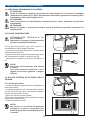
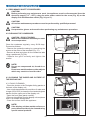
INTRODUZIONE
I
Gentile cliente,
per la sicurezza dell'operatore, i dispositivi della vetrina devono essere tenuti in costante efficienza.
Questo libretto ha lo scopo di illustrare l'uso e la manutenzione della vetrina e l'operatore ha il dovere e
la responsabilità di seguirlo.
IMPORTANTE!
- Quanto descritto in questo manuale riguarda la vostra sicurezza.
- Il Costruttore declina ogni responsabilità da un uso non previsto o contemplato nel presente
manuale.
- L'apparecchiatura NON è stata progettata per essere installata in una atmosfera a rischio di
esplosione.
- La vetrina dovrà essere installata da personale tecnico specializzato con buona conoscenza
degli impianti di refrigerazione ed elettrici, ed inoltre deve essere utilizzata da personale idoneo
ed addestrato.
- La vetrina è realizzata e progettata con gli opportuni accorgimenti al fine di garantire la sicurezza
e la salute dell'utilizzatore.
- Si raccomanda l'impiego di RICAMBI ORIGINALI; si declina ogni responsabilità per l'impiego di
ricambi non originali.
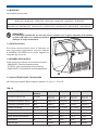
SIMBOLOGIA
Questo simbolo indica pericolo e verrà utilizzato tutte le volte che sia coinvolta la sicurezza
dell’operatore.
Questo simbolo indica cautela e vuole richiamare l’attenzione su operazioni di vitale
importanza per un funzionamento corretto e duraturo della macchina.
MANUALI ALLEGATI
In allegato al manuale di uso manutenzione, vengono consegnati i seguenti documenti:
- manuale di uso e programmazione del controllo elettronico.
- eventuale mappa parametri (solo per i casi non previsti nel manuale del controllo elettronico).
- manuale degli schemi elettrici.
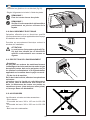
USO PREVISTO
La vetrina è prodotta per la conservazione e l'esposizione del gelato.Ogni altro uso è vivamente sconsigliato.
CONVENZIONI
Nel manuale potrebbero comparire le seguenti abbreviazioni:
TN
Temperatura Normale (Temperatura di esercizio +4°C ÷ +8°C)
BT
Bassa Temperatura (Temperatura di esercizio -18°C)
S/GR.
Unità Condensatrice Remota (motore esterno)
C/GR
Unità Condensatrice Interna (motore interno)
VAD
Vetrina con Vetri Alti Dritti
VAC
Vetrina con Vetri Alti Curvi
VBD
Vetrina con Vetri Bassi Dritti
4
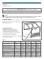
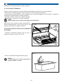
1 SPECIFICHE TECNICHE
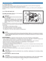
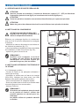
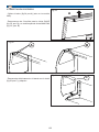
1.1 DESCRIZIONE DELLA VETRINA
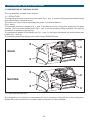
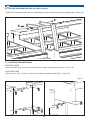
E' essenzialmente costituita da due sezioni:
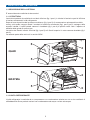
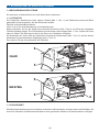
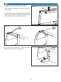
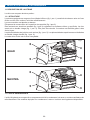
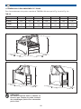
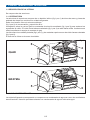
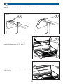
1.1.1 STRUTTURA
La struttura portante è costituita da un telaio inferiore (fig.1 pos.1) in tubolari di acciaio e parti di rifinitura
in lamiera contenente l’unità refrigerante.
Sopra di essa è posizionata la vasca monoblocco (fig.1 pos.2) di conservazione ed esposizione della
merce, sulla quale vengono fissati i montanti di alluminio anodizzato (fig.1 pos.3) per il sostegno delle
superfici vetrate. Il vetro frontale camera è riscaldato (fig.1 pos.4) è apribile verso l’alto. L’apertura è
assistita dalla spinta di molle a gas.
La vetrina ha i fianchi inferiori verniciati (fig.1 pos.5) ed i fianchi superiori in vetro camera riscaldato (fig.1
pos.6).
La restante parte della vetrina è in acciaio INOX.
Fig.1
6
4
QUAD
2
5
1
6
3
4
MAXYMA
2
5
1
3
1.1.2 UNITA’ REFRIGERANTE
L'unità refrigerante è costituita da un compressore con condensatore ad aria con uno o due ventilatori di
raffreddamento.Sono previste varianti con condensatore ad acqua o misto aria-acqua.
5
1.2 MODELLI
I modelli previsti sono:
QUAD h 1151 / h 1351
QUAD 1100 - QUAD 1600 - QUAD 2100 - QUAD 3200 - QUAD A/30°- QUAD B/30° - QUAD B/45°
MAXYMA h 1351 / h 1436
MAXYMA 1100 - MAXYMA 1600 - MAXYMA 2100 - MAXYMA 3200 - MAXYMA A/30°- MAXYMA B/30° - MAXYMA B/45°
NOTA:
Le parti costruttive che non sono a contatto con il gelato esposto sono realizzate in acciaio
AISI 304 oppure in materiale plastico atossico idoneo ai prodotti alimentari.
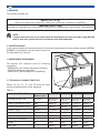
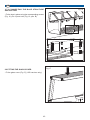
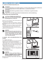
1.3 IDENTIFICAZIONE
Per qualsiasi comunicazione con il produttore o con centri assistenza citare sempre il NUMERO DI
MATRICOLA della vetrina, che è apposto sulla
targhetta (Fig.3, pos.A).
Fig.3
1.4 NORME APPLICATE
La vetrina risponde alleseguenti norme:
- 2006/95/CE (Direttiva Bassa Tensione)
- 97/23/CE (Apparecchiature a pressione)
- 2004/108/CE (Compatibilità elettromagnetica)
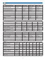
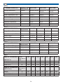
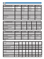
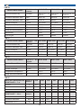
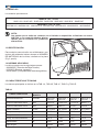
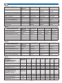
1.5 CARATTERISTICHE TECNICHE
I valori principali sono riportati in TAB.1A, TAB.1B,
TAB.1C, TAB.1D e TAB.1E.
A
TAB.1A
CARATTERISTICHE
Unità di Misura
1100 C/GR
1600 C/GR
2100 C/GR
3200 C/GR
Tensione/Fasi/Freq.
V/Ph/Hz
400/3/50 e
230/1/50
400/3/50 e
230/1/50
400/3/50 e
230/1/50
400/3/50 e
230/1/50
Potenza Assorbita 400V
W/A
890/2.94
1340/3.05
1710/3.74
2000/7.1
Potenza Assorbita 230V
W/A
480/2.5
600/3.1
810/4.2
1200/6.1
Classe Climatica
°C/UR
35°C/60%
35°C/60%
35°C/60%
35°C/60%
Temperatura Espansione
°C
-30°C
-30°C
-30°C
-30°C
Temp. di Condensazione
°C
+45°C
+45°C
+45°C
+45°C
Temp. di Esercizio
°C
-18°C
-18°C
-18°C
-18°C
Resa
W
1200
1580
2100
2780
R404a
R404a
R404a
R404a
Tipo gas
6
I
TAB.1B
CARATTERISTICHE
Unità di Misura
A/30° C/GR
B/30° C/GR
B/45° C/GR
Tensione/Fasi/Freq.
V/Ph/Hz
400/3/50 e 230/1/50
400/3/50
230/1/50
e 400/3/50
230/1/50
Potenza Assorbita 400V
W/A
890/2.94
890/2.94
890/2.94
Potenza Assorbita 230V
W/A
570/2.9
490/2.6
410/1.9
Classe Climatica
°C/UR
35°C/60%
35°C/60%
35°C/60%
Temperatura Espansione
°C
-30°C
-30°C
-30°C
Temp. di Condensazione
°C
+45°C
+45°C
+45°C
Temp. di Esercizio
°C
-18°C
-18°C
-18°C
Resa
W
1200
1200
1200
R404a
R404a
R404a
Tipo gas
e
TAB.1C
CARATTERISTICHE
Unità di Misura
1100 S/GR
1600 S/GR
2100 S/GR
3200 S/GR
Tensione/Fasi/Freq.
V/Ph/Hz
230/1/50
230/1/50
230/1/50
230/1/50
Potenza Assorbita
W/A
320/1.4
440/2.0
560/2.5
820/3.8
Classe Climatica
°C/UR
35°C/60%
35°C/60%
35°C/60%
35°C/60%
Temperatura Espansione
°C
-30°C
-30°C
-30°C
-30°C
Temp. di Esercizio
°C
-18°C
-18°C
-18°C
-18°C
TAB.1D
CARATTERISTICHE
Unità di Misura
A/30° S/GR
B/30° S/GR
B/45° S/GR
Tensione/Fasi/Freq.
V/Ph/Hz
230/1/50
230/1/50
230/1/50
Potenza Assorbita
W/A
320/1.4
405/1.8
355/1.6
Classe Climatica
°C/UR
35°C/60%
35°C/60%
35°C/60%
Temperatura Espansione
°C
-30°C
-30°C
-30°C
Temp. di Esercizio
°C
-18°C
-18°C
-18°C
TAB.1E
UNITA’ CONDENSATRICI
REMOTE 0-7 mt.
Tensione
Potenza Assorbita
Resa -30°C
UNITA’ CONDENSATRICI
REMOTE 7-22 mt.
Tensione
Potenza Assorbita
Resa -30°C
Unità di
Misura
V
W/A
1100
1600
400
400
1340/3,4 1340/3,4
2100
400
1710/5
3200
A/30°
B/30°
B/45°
400
400
400
400
2000/7.1 1340/3.4 1340/3.4 1340/3.4
W
1580
1580
2100
2780
1580
1580
1580
Unità di
Misura
1100
1600
2100
3200
A/30°
B/30°
B/45°
V
400
400
400
400
400
400
400
W/A
1340/3,4
1710/5
W
1580
2100
7
2000/7.1 2750/9.5 1340/3.4 1340/3.4 1340/3.4
2780
3100
1580
1580
1580
I
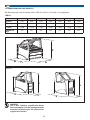
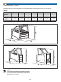
1.6 DIMENSIONI DI INGOMBRO E PESI
Per i valori di ingombro e massa vedi TAB.2A facendo riferimento a Fig.4-a e fig.4-b.
TAB.2A
1100
1600
2100
3200
A/30°
B/30°
B/45°
A (mm)
B (mm)
1190
1690
2190
3290
1587
1593
1630
1168
1168
1168
1168
1168
1168
1168
C (mm)
1151 / 1351
/ 1436
1151 / 1351
/ 1436
1151 / 1351
/ 1436
1151 / 1351
/ 1436
1151 / 1351
/ 1436
1151 / 1351
/ 1436
1151 / 1351
/ 1436
240
330
420
550
310
330
330
PESO (Kg)
Fig.4-a
C
B
A
Fig.4-b
C
B
C
A
B
NOTA:
I valori riportati in tabella non tengono
conto dell’eventuale peso di imballi
particolari richiesti dal cliente.
8
A
2 INSTALLAZIONE
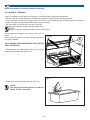
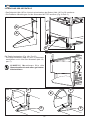
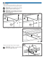
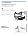
2.1 TRASPORTO
Alla vetrina vengono fissati due listelli in legno sulla struttura di base, posizionati in senso longitudinale.
La vetrina viene spedita normalmente con mezzi di trasporto via terra.
L’imballo normale è costituito da copertura in polietilene ed a richiesta l’azienda fornisce imballi
particolari.
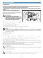
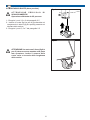
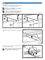
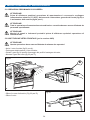
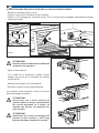
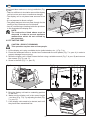
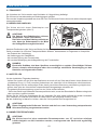
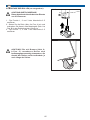
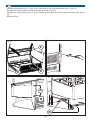
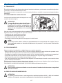
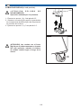
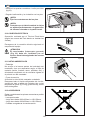
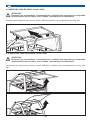
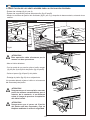
2.2 SOLLEVAMENTO E MOVIMENTAZIONE
Fig.5
La vetrina viene sollevata dal mezzo di trasporto
mediante carrello elevatore (fig.5).
ATTENZIONE!
La forcella del carrello elevatore deve
essere lunga almeno 1m/3,2Piedi.
Posizionare la vetrina ponendo il suo
baricentro al centro dell’area di appoggio
delle forcelle del carrello elevatore.
Una volta a terra si consiglia di togliere l'imballo immediatamente per poter controllare l'integrità e l'assenza
di danni dovuti al trasporto. In particolare verificare:
- lo stato delle superfici di finitura;
- i supporti di sostegno delle superfici vetrate;
- la corretta apertura del vetro frontale;
- il corretto montaggio della guarnizione di appoggio del vetro frontale.
NOTA:
Eventuali danni sono da segnalare immediatamente al vettore. In nessun caso comunque
la vetrina danneggiata può essere resa al costruttore senza preavviso o preventiva
autorizzazione scritta.
2.3 POSIZIONAMENTO
Prima di effettuare l’installazione si dovrà tener conto di:
- lasciare uno spazio di almeno 50cm (1,6ft) da qualunque ostacolo, sia lato operatore che lato cliente,
per la circolazione dell’aria nel vano motore;
- considerare gli spazi necessari per consentire l’uso e le manutenzioni in condizioni di sicurezza;
- verificare l’esistenza di un idoneo impianto di messa a terra come previsto dalle Norme.
- togliere tutte le parti dell’imballo a protezione della vetrina.
- Se la vetrina viene posizionata al centro del locale predisporre un canale sotto al pavimento o un arrivo
aereo per il cavo di alimentazione
Posizionare nello spazio stabilito la vetrina, tenendo presente che si dovranno rimuovere i due listelli alla
base della stessa prima di dare il posizionamento definitivo.
Il posizionamento va fatto in maniera tale che la vetrina risulti perfettamente in piano.
ATTENZIONE!
Questa operazione deve essere svolta con molta cautela, inserendo elementi di sicurezza
durante l’operazione.
2.4 SPECIFICHE AMBIENTALI
ATTENZIONE!
La vetrina può operare ad una temperatura ambiente massima di 35°C e 60% umidità relativa,
se l'apparecchiatura è regolarmente sottoposta a manutenzione programmata.
9
I
Si deve inoltre verificare nell’installazione (fig.6)
che:
- intorno alla vetrina vi sia una sufficiente circolazione
d’aria, ma non correnti;
- la vetrina non si trovi nelle vicinanze di sorgenti di
aria calda;
- non sia esposta direttamente ai raggi del sole;
- le griglie per il passaggio dell’aria di raffreddamento
del condensatore non siano ostruite;
- l’eventuale aria condizionata o di riscaldamento del
locale non sia indirizzata sulla vetrina stessa.
NOTA:
E’ essenziale rispettare le indicazioni
suddette per evitare malfunzionamenti,che
non saranno coperti da garanzia.
Fig.6
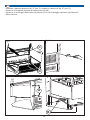
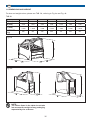
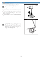
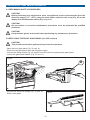
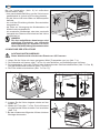
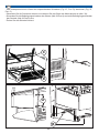
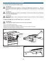
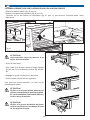
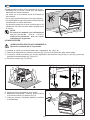
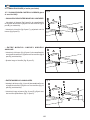
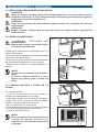
2.5 MONTAGGIO PIEDINI
ATTENZIONE PERICOLO DI SCHIACCIAMENTO!
Operazione effettuata da 2/3 persone.
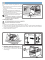
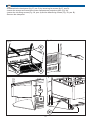
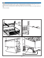
1 - Alzare la vetrina con apposito mezzo (transpallet ecc...) (fig.7-a);
2 - Posizionare sotto ai fianchi dei cartoni (fig.7-a pos.A) o elementi in modo da evitare danneggiamenti;
3 - Quando la vetrina è sollevata, mediante apposita chiave, svitare i piedini (fig.7-b pos.B) e togliere le
striscie di scorrimento (fig.7-b pos.C);
4 - Avvitare i piedini (fig.7-c pos.D);
Fig.7-b
Fig.7-a
Fig.7-c
C
B
A
5 - Appoggiare lentamente la vetrina a terra.
6 - Regolando i piedini (fig.7-c pos.D), portare la
vetrina all’altezza corretta ed in bolla (fig.7-d).
7 - Per le vetrine da canalizzare, attendere
l’assemblaggio.
10
Fig.7-d
D
I
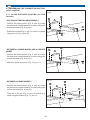
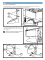
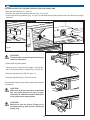
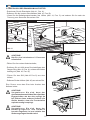
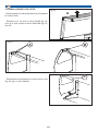
2.6 MONTAGGIO RUOTE (dove previsto).
Fig.8-a
AT T E N Z I O N E P E R I C O L O D I
SCHIACCIAMENTO!
Operazione effettuata da 2/3 persone.
B
1 - Eseguire i punti 1,2 e 3 del paragrafo 2.5
2 - Inserire la ruota (fig.8-a pos.A) avvitandola nel
componente in ottone (fig.8-a pos.B) presente nel
tubolare della vetrina;
3 - Eseguire i punti 5, 6 e 7 del paragrafo 2.5
A
Fig.8-b
ATTENZIONE! Le ruote con il freno (fig.8-b
pos.C) devono essere montate nella parte
lato operatore; inoltre il numero delle
ruote varia a seconda della lunghezza
della vetrina.
C
11
I
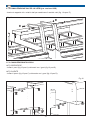
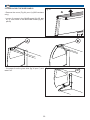
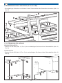
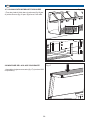
2.7 CANALIZZAZIONI (dove previsto)
2.7.1 CANALIZZAZIONE CASTELLO VETRI (per
versione VAD)
Fig.9
B
- CANALIZZAZIONE TRA MODELLI LINEARI
- Inserire il blocchetto (fig.9 pos.A) di canalizzazione
nel profilo di alluminio e fissarlo con le viti (fig.9 pos.
B) (fornite in dotazione).
B
A
C
- Inserire la vite (fig.9 pos.C) e serrarla con il dado
(fig.9 pos.D).
D
- TRA MODELLO LINEARE E MODELLO
ANGOLARE
Fig.10
B
- Inserire il blocchetto (fig.10 pos.A) di canalizzazione
nel profilo di alluminio e fissarlo con le viti (fig.10
pos.B) (fornite in dotazione).
B
A
- Avvitare posteriormente la vite (fig.10 pos.C).
C
- TRA MODELLI ANGOLARI
Fig.11
- Inserire il blocchetto (fig.11 pos.A) di canalizzazione
nel profilo di alluminio e fissarlo con le viti (fig.11
pos.B) (fornite in dotazione).
- Infilare posteriormente il perno (fig.11 pos.D) e
fissarlo con i grani (fig.11 pos.C).
B
B
A
C
C
D
12
I
2.7.2 CANALIZZAZIONE CASTELLO VETRI (per versione VBD)
- Inserire le apposite viti e relativi dadi per canalizzare il castello vetri (fig. 11b pos. E)
Fig.11b
E
E
E
E
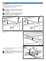
2.7.3 CANALIZZAZIONE SCOCCA
LATO OPERATORE
- Infilare i perni (fig.12 pos.A) e bloccarli con i grani (fig.12 pos.B).
LATO CLIENTE
- Infilare il perno (fig.12 pos.C) e bloccarlo con i grani (fig.12 pos.D).
Fig.12
B
B
A
A
B
D
B
13
C
D
I
LATO CLIENTE
- Bloccare le due strutture (fig.13) mediante apposita
vite (fig.13 pos.A) e dado (fig.13 pos.B).
NOTA: per canalizzare due gelaterie
utilizzare il foro C (fig. 13)
NOTA: per canalizzare una gelateria ed una
pasticceria utilizzare il foro D (fig. 13)
Fig.13
B
B
A
A
C
D
- Appoggiare la staffa di canalizzazione (fig.14 pos.
A).
Fig.14
A
- Inserire il vetro (fig.15 pos. A) sopra la staffa
precedentemente montata.
NOTA! Controllare che attaccato al vetro vi
sia la guarnizione (fig.15 pos. B).
14
Fig.15
B
A
I
2.7.4 CANALIZZAZIONE BASAMENTO/
TUBOLARI
Fig.16
- Fissare le gambe con le apposite viti (fig.16 pos. A)
e dadi (fig.16 pos. B).
A
B
A
2.8 MONTAGGIO CAPPELLO IN VETRO
Fig.17
- Montare il cappello in vetro (fig.17) (solo versione
VAD).
15
B
I
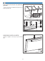
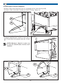
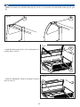
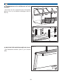
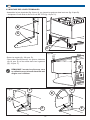
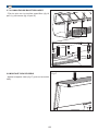
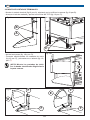
2.9 MONTAGGIO FIANCHI TERMINALI
- Montare il fianco terminale (fig.18 pos. A), avvitando nei fori i perni (fig.18 pos.B).
- Accostare il fianco terminale e serrare le viti M6 TCEI (fig. 18 pos. C).
Fig.18
B
A
C
- Serrare i grani (fig. 18b, pos. D)
- Collegare elettricamente i fianchi in vetro (fig.19,
pos. E) ed infilarli nella propria sede (fig. 19, pos.
F).
Fig.18b
NOTA! Montare i fianchi in vetro con
la traccia elettrificata rivolta verso
l’esterno.
Fig.19
F
D
E
F
E
F
F
16
I
- Serrare le 2 viti per la vetrina QUAD (fig. 20, pos. A) od una vite per la vetrina MAXYMA (fig. 20, pos.
B).
Fig.20
A
B
Fig.21
C
- Montare il pannello anteriore (fig. 21, pos. C)
avvitando le relative viti (fig. 21, pos. D).
D
Fig.21b
- Montare lo zoccolo tramite aggancio magnetico
(fig. 21b, pos. E).
17
E
D
I
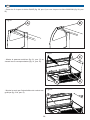
Fig.22
- Infilare gli Scorrevoli se previsti (fig.22).
- Regolare l’allineamento e la messa in bolla con i
piedini.
NOTA!
Fissare i controdadi dei piedini.
NOTA!
Controllare che il vetro frontale della vetrina
aderisca perfettamente alla guarnizione in
silicone posta sul frontale.
2.10 COLLEGAMENTO ELETTRICO
Operazione eseguita dal Tecnico Elettricista (secondo
le norme del Paese dove le vetrine sono installati).
Provvedere al collegamento elettrico seguendo lo
schema dell’impianto.
ATTENZIONE!
Il sezionatore (interruttore generale)
(Fig. 23) deve essere installato a cura del
Tecnico Elettricista secondo le norme
vigenti.
2.11 NOTE AMBIENTALI
- Imballaggio
Non gettare nella spazzatura eventuali parti
dell’imballo del banco, ma selezionarli a seconda del
tipo di materiale (Cartone, legno, acciaio, poliestere,
ecc...) e smaltirli a seconda della normativa vigente
nel paese di utilizzo del banco.
- Fine servizio
Alla fine della vita del banco si dovrà:
Recuperare tutto il refrigerante dal circuito, svuotarlo
di tutto l’olio contenuto a qualsiasi titolo nello
stesso, togliere tutte le parti in gomma (es. O-ring,
guarnizioni), inviarlo infine alla rottamazione.
2.12 ACCESSORI
Sono da considerare parti accessorie a richiesta
del cliente:
- Lavaporzionatore
- Set di vaschette 360x165mm h=120-150mm;
- Set di vaschette 360x250mm h=120-150mm;
- Vaschetta raccogli condensa.
18
Fig.23
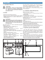
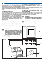
3 FUNZIONAMENTO
3.1 OPERAZIONI PRELIMINARI DI CONTROLLO
ATTENZIONE!
Accertarsi che l’interrutore generale
dell’impianto elettrico sia disinserito
("0"- OFF) prima di iniziare l'avviamento
della vetrina.
L’accensione si effettua semplicemente posizionando
l’interruttore sezionatore vetrina (pos.1) su “I” “ON” e
premendo il tasto ON/OFF (pos.2).
Se necessario premere il pulsante illuminazione
vetrina (pos.3).
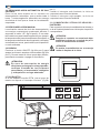
3.2.1 SPIE LUMINOSE (fig.25)
3.2 AVVIAMENTO
ILLUMINAZIONE (pos.9)
- spia accesa per illuminazione vetrina.
- Togliere tutte le protezioni.
- Assicurarsi che la vetrina sia pulita e ben igienizzata ALLARME (pos.10)
(vedi PARTE 4 “MANUTENZIONE ORDINARIA”). - spia accesa per allarme attivo; lampeggiante per
allarme tacito.
VENTOLE (pos.11)
ATTENZIONE!
Prima di poter immettere il prodotto - spia accesa per ventola in funzione.
nella vetrina occorre attendere circa 60 SBRINAMENTO (pos.12)
minuti dall’avviamento per stabilizzare la spia accesa per sbrinamento in corso; lampeggiante
per attivazione manuale.
temperatura di funzionamento.
COMPRESSORE O RELÉ (pos.13)
Operare sul gruppo comandi della vetrina che - spia accesa per compressore acceso; lampeggiante
prevede (fig.24):
per ritardo, protezione o attivazione bloccata.
- INTERRUTTORE SEZIONATORE VETRINA
(pos.1);
3.3 REGOLAZIONE DELLA TEMPERATURA
- TASTO ON/OFF (pos.2);
- TASTO ILLUMINAZIONE E PORTAGUSTI - Premere il tasto SET (fig.24 pos.4) per 2 secondi;
(pos.3);
premere successivamente entro 3 secondi i tasti UP
- TA S TO P E R L’ I M P O S TA Z I O N E D E L L A (fig.24 pos.6) o DOWN (fig.24 pos.7) per aumentare o
TEMPERATURA (pos.4).
diminuire la temperatura fino al valore desiderato.
- TASTO PER ACCEDERE AL MENU (pos.5).
- Attendere 10 secondi, automaticamente lo
- TASTO PER AUMENTARE IL VALORE DELLA strumento memorizzerà il valore impostato e il visore
TEMPERATURA (pos.6).
mostrerà il valore della temperatura. In alternativa
- TASTO PER DIMINUIRE IL VALORE DELLA premere nuovamente il tasto SET.
TEMPERATURA (pos.7).
- VISORE LUMINOSO (pos.8).
Fig.24
5
6
8
°C
Fig.25
3
12
11
13
M
set
°C
((( (((
7 4
0
2
1
((( (((
1
10
19
9
I
da Gelateria.
Quando l’interruttore è spento, la vetrina si comporterà
Questa vetrina è dotata di un sistema si sbrinamento da Pasticceria.
automatico, che si attiva ogni 4 ore. Lo sbrinamento
automatico provvede ad eliminare il ghiaccio che si forma 3.8 COMMUTAZIONE GELATERIA-PASTICCERIA
Per commutare la vetrina in modalità Gelateria (o
sulle alette dell’evaporatore.
Pasticceria) è sufficiente posizionare l’interruttore nella
posizione corrispondente.
3.5 SBRINAMENTO MANUALE
3.4 SBRINAMENTO AUTOMATICO A GAS CALDO
ATTENZIONE!
Dopo la commutazione si raccomanda di
lasciare stabilizzare la vetrina per almeno 30
minuti prima dell’uso.
L'attivazione manuale del ciclo di sbrinamento si ottiene
tenendo premuto per 5 secondi il tasto "UP" (fig.24
pos.6). Se non vi sono le condizioni per lo sbrinamento,
(per esempio la temperatura della sonda evaporatore è
superiore alla temperatura di fine sbrinamento), il display
lampeggierà per tre volte, per segnalare che l'operazione
non verrà effettuata.
ATTENZIONE!
Si consiglia di effettuare una pulizia della
vetrina in occasione del cambio di modalità.
3.6 FERMATA
Premere il tasto ON/OFF (fig.26a pos.2) per spegnere
la vetrina senza agire sul sezionatore (fig.26a pos.1). In
questo modo la vetrina rimane sotto tensione, permettendo
ancora di accendere/spegnere l’illuminazione.
Fig.26b
ATTENZIONE!
In caso di interruzione dell’energia elettrica per
un lungo periodo, verificare lo stato dei prodotti
deperibili ed eventualmente asportarli e riporli
in un luogo idoneo.
1
3.7 OPZIONE BT-TN
Se è installata l’opzione BT-TN, accanto al gruppo comandi
è posizionato un interruttore luminoso (fig.26b pos.1).
Quando l’interruttore è illuminato, la vetrina si comporterà
Fig.26a
°C
M
2
set
((( (((
0
1
1
20
I
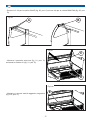
3.9 APERTURA CAPPELLO IN VETRO (versione VBD)
ATTENZIONE!
Durante l’uso, l’assemblaggio, la manutenzione o qualsiasi altra operazione che comprenda
la manipolazione dei vetri, fare attenzione a manovrarli con delicatezza.
L'apertura del cappello in vetro per la versione VBD va effettuata come raffigurato (fig. 26c).
Fig.26c
3.10 APERTURA VETRO ANTERIORE (versione VAD)
ATTENZIONE!
Durante l’uso, l’assemblaggio, la manutenzione o qualsiasi altra operazione che comprenda
la manipolazione dei vetri, fare attenzione a manovrarli con delicatezza.
L'apertura del vetro anteriore per la versione VAD / VAC va effettuata come raffigurato (fig. 26d,
26e).
Fig.26d
Fig.26e
21
4 MANUTENZIONE ORDINARIA
4.1 OPERAZIONI PRELIMINARI DI SICUREZZA
ATTENZIONE!
Prima di effettuare qualsiasi operazione di manutenzione è necessario scollegare
l’alimentazione elettrica ("0"-OFF), disinserendo l’interruttore generale del locale (fig.23) o
il sezionatore della vetrina (fig.24 pos.1).
ATTENZIONE!
Tutte le operazione di manutenzione ordinaria devono essere effettuate da personale
specializzato.
ATTENZIONE!
Munirsi di guanti e indumenti protettivi prima di effettuare qualsiasi operazione di
manutenzione.
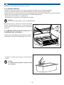
4.2 PULIZIA CONDENSATORE
Fig.27
AT T E N Z I O N E P E R I C O L O D I
SCOTTATURA!
Attendere che il gruppo condensatore sia
arrivato a temperatura ambiente.
Pulire periodicamente ogni 20-30 giorni il
condensatore come di seguito indicato:
- rimuovere la protezione svitando le viti poste ai lati
della mascherina (fig.27);
- togliere la polvere e lo sporco presente nelle alette
del condensatore usando un pennello (fig.28).
- riposizionare la griglia al suo posto riavvitando le
viti.
NOTA!
Non usare aria compressa, aria forzata
o vapore .
Non usare spazzole metalliche o altri
oggetti che possono graffiare o piegare
le alette.
4.3 PULIZIA INTERNO ED ESTERNO DELLA
VETRINA
4.3.1 Pulizia giornaliera:
- Chiudere la tendina o gli scorrevoli in plexiglass sul
retro della vetrina;
- Inumidire uno straccio con una soluzione di acqua
e aceto (50%-50%) e pulire i vetri frontali, laterali e
la parte superiore della vetrina;
- Aprire con cautela il vetro frontale;
- Rimuovere i prodotti dalla vetrina e riporli in un luogo
idoneo alla conservazione;
- Pulire la superficie interna.
NOTA!
Nel caso in cui la vetrina sia dotata di
piani/parti in marmo, provvedere alla
pulizia di questi solo con prodotti specifici
o naturali.
22
Fig.28
I
Non usare mai prodotti abrasivi o acidi in genere.
4.3.2 PULIZIA SETTIMANALE:
Pulire la vetrina almeno una volta alla settimana facendola coincidere con uno sbrinamento.
- Rimuovere le vaschette gelato e relativi supporti. Pulire usando acqua tiepida;
- Pulire l'interno vasca evitando l’uso di troppa acqua che può danneggiare i circuiti elettrici o riempire la
vaschetta raccoglicondensa (quando presente).
- Asciugare l'interno vasca con un panno asciutto;
- Riposizionare i supporti e le relative vaschette
NOTA!
Usare sempre poca acqua ed asciugare accuratamente.
Non lavare mai la vetrina con getti di acqua diretti.
Evitare assolutamente l’uso di alcool puro e altri
prodotti di pulizia per le superfici esterne.
Fig.29
C
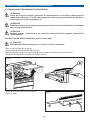
4.4 PULIZIA VASCHETTA RACCOGLICONDENSA
(OPTIONAL)
- Smontare il pannello anteriore (fig. 29, pos. C)
svitando le relative viti (fig. 29, pos. D).
D
Fig.31
- Pulire la vaschetta raccoglicondensa (fig.31)
NOTA!
La vaschetta può essere asportata in
quanto fissata a “scatto”.
23
D
5 MANUTENZIONE STRAORDINARIA
5.1 OPERAZIONI PRELIMINARI DI SICUREZZA
ATTENZIONE!
Prima di effettuare qualsiasi operazione di manutenzione è necessario scollegare
l’alimentazione elettrica ("0"-OFF), disinserendo l’interruttore generale del locale (fig.23) o
il sezionatore della vetrina (fig.24 pos.1).
ATTENZIONE!
Tutte le operazione di manutenzione straordinaria o correttiva devono essere effettuate da
personale specializzato.
ATTENZIONE!
Munirsi di guanti e indumenti protettivi prima di effettuare qualsiasi operazione di
manutenzione.
5.2 SOSTITUZIONE VETRO FRONTALE (per la versione VAD)
ATTENZIONE!
Questa operazione deve essere effettuata da almeno due operatori.
- Aprire il vetro frontale (fig.32 pos.A);
- Scollegare elettricamente il vetro frontale;
- Svitare i grani (fig.32 pos.B) di serraggio dei profili di sostegno del vetro;
- Allentare i grani del vetro (fig.33 pos.C);
Fig.32
B
A
Fig.33
- Sfilare il cuneo di alluminio (Fig.33 pos.D);
- Sfilare il vetro.
D
24
C
I
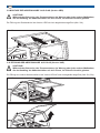
5.3 SOSTITUZIONE FIANCHI
Fig.34
A
- Togliere il tettino (fig.34 pos.A) (solo versione
VAD).
- Svitare le 2 viti per la vetrina QUAD (fig. 35, pos.
A) od una vite per la vetrina MAXYMA (fig. 35,
pos. B).
Fig.35
A
B
- Scollegare elettricamente il fianco con il vetro (fig.36
pos.C) e sfilarlo.
25
Fig.36
C
I
- Smontare il pannello anteriore (fig. 37, pos. C) svitando le relative viti (fig. 37, pos. D).
- Svitare le viti e togliere la griglia del vano motore (fig.38).
- Svitare le viti di fissaggio della vasca (fig.39 pos.A) e le viti di fissaggio basamenti (fig.39 pos.B)
- Sfilare il fianco;
Fig.38
Fig.37
C
D
D
Fig.39
A
B
26
I
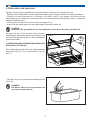
5.4 SOSTITUZIONE DEI VENTILATORI PER LA CIRCOLAZIONE FORZATA
- Estrarre le vaschette (fig.41 pos.A);
- Togliere i piani interni di protezione (fig.41 pos.B);
- svitare le viti di fissaggi del ventilatore (fig.41 pos.C) e dopo averlo scollegato elettricamente estrarlo
dalla propria sede.
A
C
B
Fig.41
5.5 SOSTITUZIONE PISTONI
Fig.42
ATTENZIONE!
Questa operazione deve essere effettuata
da almeno due operatori.
- Aprire il vetro anteriore.
B
A
- Con l’ausilio di un punteruolo, togliere l’anello
seeger (fig.42 pos.A) di fissaggio del pistone
(fig.42 pos.B).
- Sfilare il perno (fig.42 pos.C) dal pistone.
- Smontare il pistone (fig.42) dalla sua sede.
Un operatore dovrà sostenere il vetro al momento
dello smontaggio del pistone.
ATTENZIONE!
Assicurarsi che il nuovo pistone da
montare abbia le stesse caratteristiche
del vecchio altrimenti c’è il rischio, se
montato uno diverso, di esplosione del
vetro frontale.
ATTENZIONE!
Assicurarsi che il perno di fissaggio del
pistone sia ben inserito e che venga
bloccato mediante l’anello di sicurezza.
27
C
I
5.6 RABBOCCO OLIO COMPRESSORE
Fig.43
- Chiudere il rubinetto dell’aspirazione (fig.43 pos.
F);
- chiudere il rubinetto di mandata (fig.43 pos.B);
- aprire il tappo di carico dell’olio (fig.43 pos.C) e
rabboccare l’olio;
- richiudere il tappo dell’olio (fig.43 pos.C);
- togliere il tappo e collegare la pompa del vuoto al
raccordo (fig.43 pos.E);
- accendere la pompa e lasciare aspirare per circa
15 minuti;
- spegnere la pompa;
- aprire completamente il rubinetto (fig.43 pos.F);
- staccare il tubo della pompa e ripristinare il tappo
del raccordo;
- aprire completamente il rubinetto di mandata (fig.43
pos.B).
C
ATTENZIONE!
Il rabbocco dell’olio va effettuato in caso
di necessità.
5.7 SOSTITUZIONE OLIO COMPRESSORE
- Chiudere il rubinetto dell’aspirazione (fig.43 pos.
F);
- chiudere il rubinetto di mandata (fig.43 pos.B);
- svitare il tappo di scarico dell’olio (fig.43 pos.D), far
defluire l’olio e richiudere il tappo.
NOTA: sostituire la rondella in rame ad
ogni apertura del tappo di scarico;
- aprire il tappo di carico dell’olio (fig.43 pos.C) e
ricaricare l’olio;
- richiudere il tappo dell’olio (fig.43 pos.C);
- togliere il tappo e collegare la pompa del vuoto al
raccordo (fig.43 pos.E);
- accendere la pompa e lasciare aspirare per circa
15 minuti;
- spegnere la pompa;
- aprire completamente il rubinetto (fig.43 pos.F);
- staccare il tubo della pompa e ripristinare il tappo
del raccordo;
- aprire completamente il rubinetto di mandata (fig.43
pos.B).
E
28
F
B
D
I
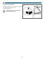
5.8 PULIZIA EVAPORATORE
Fig.44
- Estrarre manualmente le due griglie “ripresa aria”
sottostanti al portagusti (Fig.44)
- Pulire l’evaporatore.
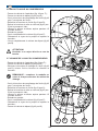
ATTENZIONE! PERICOLO DI TAGLIO!
Utilizzare appositi guanti.
29
GB
Index
INTRODUCTION
31
1 TECHNICAL SPECIFICATIONS
1.1 DESCRIPTION OF THE DISPLAY UNIT
1.2 MODELS
1.3 IDENTIFICATION
1.4 REFERENCE STANDARDS
1.5 TECHNICAL CHARACTERISTICS
1.6 DIMENSIONS AND WEIGHT
32
32
33
33
33
33
35
2 INSTALLATION
2.1 TRANSPORTATION
2.2 LIFTING AND HANDLING
2.3 POSITIONING
2.4 ENVIRONMENTAL SPECIFICATIONS
2.5 FITTING THE FEET
2.6 FITTING THE WHEELS (where supplied)
2.7 ASSEMBLING THE CONNECTION DUCTING (where supplied)
2.8 FITTING THE GLASS COVER
2.9 FITTING THE END PANELS
2.10 ELECTRICAL CONNECTION
2.11 NOTES ON THE ENVIRONMENT
2.12 ACCESSORIES
36
36
36
36
36
37
38
39
42
43
45
45
45
3 OPERATING THE EQUIPMENT
3.1 PRELIMINARY CHECKS
3.2 START-UP
3.3 TEMPERATURE ADJUSTMENT
3.4 AUTOMATIC HOT GAS DEFROSTING
3.5 MANUAL DEFROSTING
3.6 SWITCHING THE APPLIANCE OFF
3.7 BT-TN OPTION
3.8 ICE-CREAM - PASTRY DISPLAY UNIT SWITCHING
3.9 OPENING THE GLASS COVER (VBD versions)
3.10 OPENING THE FRONT GLASS PANEL (VAD versions)
46
46
46
46
47
47
47
47
47
48
48
4 ROUTINE MAINTENANCE
4.1 PRELIMINARY SAFETY PROCEDURES
4.2 CLEANING THE CONDENSER
4.3 CLEANING THE INSIDE AND OUTSIDE OF THE DISPLAY UNIT
4.4 CLEANING THE CONDENSATE COLLECTOR TRAY (OPTIONAL)
49
49
49
49
50
5 NON-ROUTINE MAINTENANCE
5.1 PRELIMINARY SAFETY PROCEDURES
5.2 REPLACING THE FRONT GLASS PANEL (for VAD versions)
5.3 REPLACING THE SIDE PANELS
5.4 REPLACING THE FORCED CIRCULATION COOLING FANS
5.5 REPLACING THE PISTONS
5.6 TOPPING UP THE COMPRESSOR OIL
5.7 REPLACING THE COMPRESSOR OIL
5.8 CLEANING THE EVAPORATOR
51
51
51
52
54
54
55
55
56
30
INTRODUCTION
GB
Dear Customer,
for the safety of the Operator, the devices within the display unit must be kept in good working
order. This manual is designed to provide a guide to the operation and maintenance of the display
unit; the Operator is obliged to adhere to the instructions contained within it.
IMPORTANT!
- The information provided in this manual concerns your safety.
- The Manufacturer declines all liability if the product is not used in accordance with the instructions
given in this manual, or if it is used for any unauthorised purpose which is not listed in this
manual.
- The equipment was NOT designed for installation in an atmosphere which is at risk of
explosion.
- The display unit must be installed by specialised technical personnel who are familiar with electrical
and refrigeration systems, and must be operated by suitably trained staff.
- The display unit is created and designed so that it features all necessary precautions, in order to
safeguard the health of the user.
- We recommend the use of AUTHENTIC SPARE PARTS; we decline all liability wherever nonauthentic spare parts are used.
SYMBOLS USED
This symbol indicates a hazard and will be used every time the safety of the operator may
be placed at risk.
This symbol indicates caution and is intended to attract the attention of the user to procedures
of fundamental importance for the correct long-term operation of the machine.
MANUALS ENCLOSED
The following documentation is enclosed with the operation and maintenance manual:
- Operation and programming manual for the electronic controls.
- Parameters map (only for cases not included in the electronic controls manual).
- Electrical diagrams manual.
INTENDED USE
The display unit is manufactured for ice-cream storage and display purposes. We strongly advise
against using it for any other purpose.
CONVENTIONS
In the manual the following abbreviations may appear:
TN
Normal Temperature (operating temperature +4°C to +8°C)
BT
Low Temperature (operating temperature -18°C)
S/GR.
Remote Condenser Unit (external motor)
C/GR
Internal Condenser Unit (internal motor)
VAD
Tall Straight Glass display cabinet
VAC
Tall Curved Glass display cabinet
VBD
Short Straight Glass display cabinet
31
1 TECHNICAL SPECIFICATIONS
1.1 DESCRIPTION OF THE DISPLAY UNIT
The unit essentially consists of two sections:
1.1.1 STRUCTURE
The supporting structure consists of a lower frame (Fig. 1, pos. 1) in steel ducting and sheet metal finishing
parts containing the refrigeration unit.
The enbloc tub, used to store and display the goods, is positioned above it
(Fig.1, pos.2).
The anodised aluminium uprights (Fig. 1, pos. 3) are fixed to the tub, acting as a support for the glass
surfaces. The front double glazed panel (Fig. 1, pos. 4) can be opened by lifting it upwards. The opening
mechanism is assisted by gas springs.
The painted side panels of the display unit (Fig. 1, pos. 5), the upper side panels are double-glazed and
heated (Fig. 1, pos. 6).
The remaining part of the display unit is made using STAINLESS steel.
Fig.1
6
4
QUAD
2
5
1
6
3
4
MAXYMA
2
5
1
3
1.1.2 REFRIGERATION UNIT
The refrigeration unit consists of a compressor with an air condenser, fitted with one or two cooling fans.
Models with water condensers or mixed air-water condensers are also available.
32
GB
1.2 MODELS
The models available are:
QUAD h 1151 / h 1351
QUAD 1100 - QUAD 1600 - QUAD 2100 - QUAD 3200 - QUAD A/30°- QUAD B/30° - QUAD B/45°
MAXYMA h 1351 / h 1436
MAXYMA 1100 - MAXYMA 1600 - MAXYMA 2100 - MAXYMA 3200 - MAXYMA A/30°- MAXYMA B/30° - MAXYMA B/45°
NOTE:
Components which are not in contact with the displayed ice-cream are made using AISI 304
steel or non-toxic plastic which is suitable for use with foodstuffs.
1.3 IDENTIFICATION
In any communication with the manufacturer or with technical assistance centres, always quote the SERIAL
NUMBER of the display unit (this can be found on
the data plate (Fig. 3,pos.A).
Fig.3
1.4 REFERENCE STANDARDS
The display unit complies with the following
regulations:
- 2006/95/EC (Low Voltage equipment Directive)
- 97/23/EC (Pressure equipment)
- 2004/108/EC (Electromagnetic compatibility)
1.5 TECHNICAL CHARACTERISTICS
Tables 1A, 1B, 1C, 1D and 1E show the main
technical characteristics of this appliance.
TAB.1A
CHARACTERUSTICS
A
U n i t
o f
Measurement
1100 C/GR
Voltage/Phases/Freq.
V/Ph/Hz
400/3/50 and 400/3/50 and 400/3/50 and 400/3/50 and
230/1/50
230/1/50
230/1/50
230/1/50
Power Consumption 400V
W/A
890/2.94
1340/3.05
1710/3.74
2000/7.1
Power Consumption 230V
W/A
480/2.5
600/3.1
810/4.2
1200/6.1
Climatic Class
°C/UR
35°C/60%
35°C/60%
35°C/60%
35°C/60%
Expansion Temperature
°C
-30°C
-30°C
-30°C
-30°C
Condensation Temperature
°C
+45°C
+45°C
+45°C
+45°C
Operating Temperature
°C
-18°C
-18°C
-18°C
-18°C
Output
W
1200
1580
2100
2780
R404a
R404a
R404a
R404a
Gas Type
33
1600 C/GR
2100 C/GR
3200 C/GR
GB
TAB.1B
CHARACTERUSTICS
Voltage/Phases/Freq.
Power Consumption 400V
Power Consumption 230V
Climatic Class
Expansion Temperature
Condensation Temperature
Operating Temperature
Output
Gas Type
U n i t
o f A/30° C/GR
B/30° C/GR
Measurement
V/Ph/Hz
400/3/50 e 230/1/50 4 0 0 / 3 / 5 0
230/1/50
W/A
890/2.94
890/2.94
W/A
570/2.9
490/2.6
°C/UR
35°C/60%
35°C/60%
°C
-30°C
-30°C
°C
°C
W
+45°C
-18°C
1200
R404a
B/45° C/GR
e 400/3/50
230/1/50
890/2.94
410/1.9
35°C/60%
-30°C
+45°C
-18°C
1200
R404a
e
+45°C
-18°C
1200
R404a
TAB.1C
CHARACTERUSTICS
1600 S/GR
2100 S/GR
3200 S/GR
Voltage/Phases/Freq.
U n i t
o f 1100 S/GR
Measurement
V/Ph/Hz
230/1/50
230/1/50
230/1/50
230/1/50
Power Consumption 230V
Climatic Class
Expansion Temperature
W/A
°C/UR
°C
320/1.4
35°C/60%
-30°C
440/2.0
35°C/60%
-30°C
560/2.5
35°C/60%
-30°C
820/3.8
35°C/60%
-30°C
Operating Temperature
°C
-18°C
-18°C
-18°C
-18°C
TAB.1D
CHARACTERUSTICS
B/30° S/GR
B/45° S/GR
Voltage/Phases/Freq.
Power Consumption 230V
Climatic Class
Expansion Temperature
U n i t
o f A/30° S/GR
Measurement
V/Ph/Hz
230/1/50
W/A
320/1.4
°C/UR
35°C/60%
°C
-30°C
230/1/50
405/1.8
35°C/60%
-30°C
230/1/50
355/1.6
35°C/60%
-30°C
Operating Temperature
°C
-18°C
-18°C
-18°C
TAB.1E
REMOTE CONDENSER Unit of
1100
1600
MeasureUNITS 0-7 m
ment
Voltage
V
400
400
Power Consumption
W/A
1340/3,4 1340/3,4
Output -30°C
W
1580
1580
Unit of
1100
REMOTE CONDENSER
MeasureUNITS 7-22 m
ment
Voltage
V
400
Power Consumption
W/A
1340/3,4
Output -30°C
W
1580
1600
400
1710/5
2100
34
2100
400
1710/5
2100
2100
3200
A/30°
B/30°
B/45°
400
400
400
400
2000/7.1 1340/3.4 1340/3.4 1340/3.4
2780
1580
1580
1580
3200
A/30°
B/30°
B/45°
400
400
400
400
400
2000/7.1 2750/9.5 1340/3.4 1340/3.4 1340/3.4
2780
3100
1580
1580
1580
GB
1.6 DIMENSIONS AND WEIGHT
For size and weight values, please see TAB. 2A, referring to Fig. 4a and Fig. 4b.
TAB.2A
1100
1600
2100
3200
A/30°
B/30°
B/45°
A (mm)
B (mm)
1190
1690
2190
3290
1587
1593
1630
1168
1168
1168
1168
1168
1168
1168
C (mm)
1151 / 1351
/ 1436
1151 / 1351
/ 1436
1151 / 1351
/ 1436
1151 / 1351
/ 1436
1151 / 1351
/ 1436
1151 / 1351
/ 1436
1151 / 1351
/ 1436
240
330
420
550
310
330
330
WEIGHT
(Kg)
Fig.4-a
C
B
A
Fig.4-b
C
B
C
A
B
NOTE:
The values listed in the table do not take
into account the weight of any packaging
requested by the customer.
35
A
2 INSTALLATION
2.1 TRANSPORTATION
Two wooden strips are fixed onto the base structure of the display unit and positioned lengthways.
The display unit is usually shipped using overland transport.
Normal packaging consists of a polyethylene cover; the company provides special packaging on
request.
Fig.5
2.2 LIFTING AND HANDLING
The display unit should be lifted out of the transporting
vehicle using a fork lift truck (fig. 5).
WARNING!
The lifting platform fork must be at least 1
m / 3.2 ft long.
Position the display unit correctly by
placing its centre of gravity in the middle
of the support area on the lifting vehicle
forks.
Once the equipment is on the ground, we recommend the packaging is removed immediately in order to
check the item is intact and has not been damaged during transportation. The following should be checked
in particular:
- The condition of the finished surfaces.
- The supporting elements for the glass surfaces.
- The opening mechanism of the front glass panel.
- The adherence of the seal cushioning the front glass panel.
NOTE:
The carrier must be notified of any damage immediately. Under no circumstances, however,
may the damaged display unit be returned to the manufacturer without prior notice or written
authorisation.
2.3 POSITIONING
Before installing the equipment, please take into account the following considerations:
- Leave a space of at least 50 cm (1.6 ft) between the unit and any other item, on both the operator side
and the customer side, so that air can circulate in the motor compartment.
- Calculate the space required to operate the unit and perform maintenance in safe conditions.
- Make sure there is a suitable earthing system as specified by current legislation.
- Remove all packaging protecting the display unit.
- If the display unit is located in the centre of the room, an under-floor or overhead channel must be provided
for the power supply cable.
Place the display unit in the chosen position, remembering to remove the two strips at the base of the unit
before the final position is achieved.
The display unit should be positioned in such a way that it is perfectly level.
CAUTION!
This procedure must be performed very carefully, employing all necessary safety
precautions.
2.4 ENVIRONMENTAL SPECIFICATIONS
CAUTION!
The display unit can operate at a maximum room temperature of 35°C and at 60% relative
humidity, as long as the equipment regularly undergoes scheduled maintenance.
36
GB
You should also make sure, during installation (Fig.
6), that:
- There is sufficient air circulation around the display
unit but not so much as to constitute a draught.
- The display unit is not placed near sources of hot
air.
- It is not exposed to direct sunlight.
- The grilles designed to let air pass through for the
cooling of the condenser are not blocked.
- Any air conditioning or heating inside the premises
is not directed at the display unit.
NOTE:
The instructions listed above must be
observed in order to prevent appliance
malfunctions which are not covered by
the guarantee.
Fig.6
2.5 FITTING THE FEET
CAUTION - RISK OF CRUSHING!
This operation requires two or three people.
1 - Lift the display unit using a suitable device (pallet stacker, etc...) (Fig. 7-a).
2 - Place the cardboard boxes or similar items underneath the side panels (Fig. 7-a, pos. A) in order to
prevent damage from occurring.
3 - While the display unit is lifted, loosen the feet using a suitable wrench (Fig. 7-b, pos. B) and remove
the runners (Fig. 7b, pos. C).
4 - Screw in the feet (Fig. 7-c, pos. D).
Fig.7-b
Fig.7-a
Fig.7-c
C
B
A
5 - Bring the display unit back to a standing position
on the floor.
6 - Make sure the display unit is the correct height
- and level (Fig. 7-d) - by adjusting the feet (Fig.
7-c, pos. D).
7 - If the display units need to be ducted, wait until
they have been assembled first.
Fig.7-d
37
D
GB
2.6 FITTING THE WHEELS (where supplied)
Fig.8-a
CAUTION - RISK OF CRUSHING!
This operation requires two or three
people.
B
1 - Perform steps 1, 2 and 3 listed in paragraph
2.5.
2 - Fit the wheel (Fig. 8-a, pos. A) by screwing it
into the brass component (Fig. 8-a, pos. B) on the
display unit ducting.
3 - Perform steps 5, 6 and 7 listed in paragraph
2.5.
A
Fig.8-b
CAUTION! The wheels fitted with a brake
(Fig. 8-b, pos. C) should be fixed to the
operator side of the product; the number
of wheels will vary depending on the
length of the display unit.
C
38
GB
2.7 ASSEMBLING THE CONNECTION DUCTING
(where supplied)
2.7.1 GLASS SHELVING DUCTING (for VAD
versions)
- DUCTING BETWEEN LINEAR MODELS
Fig.9
B
B
A
- Position the ducting block (Fig. 9, pos. A) inside
the aluminium contours and fix it in place using the
screws provided (Fig. 9, pos. B).
C
- Position the screw (Fig. 9, pos. C) and fix it in place
using the nut (Fig. 9, pos. D).
D
Fig.10
- BETWEEN A LINEAR MODEL AND A CORNER
MODEL
B
B
A
- Position the ducting block (Fig. 9, pos. A) inside
the aluminium contours and fix it in place using the
screws provided (Fig. 9, pos. B).
C
- After this, tighten the screw (Fig. 10, pos. C).
Fig.11
- BETWEEN CORNER MODELS
- Position the ducting block (Fig. 9, pos. A) inside
the aluminium contours and fix it in place using the
screws provided (Fig. 9, pos. B).
- Then slot in the pin (Fig. 11, pos. D) and fix it in
place using the dowels (Fig. 11, pos. C).
B
B
A
C
C
D
39
GB
2.7.2 GLASS SHELVING DUCTING (for VBD versions)
- Position the relevant screws and corresponding nuts for ducting the glass shelf display (fig. 11b pos. E)
Fig.11b
E
E
E
E
2.7.3 DUCTING THE BODYWORK
OPERATOR SIDE
- Slot in the pins (Fig. 12, pos. A) and lock them in place using the dowels (Fig. 12, pos. B).
CUSTOMER SIDE
- Slot in the pin (Fig. 12, pos. C) and lock it in place using the dowels (Fig. 12, pos. D).
Fig.12
B
B
A
A
B
D
B
40
C
D
GB
CUSTOMER SIDE
- Lock the two structures into position (Fig. 13) using
a suitable screw (Fig. 13, pos. A) and nut (Fig. 13,
pos. B).
NOTE: when ducting two ice-cream
display units use hole C (Fig. 13)
NOTE: when ducting an ice-cream display
unit and a pastry display unit use hole D
(Fig. 13)
Fig.13
B
B
A
A
C
D
Fig.14
- Position the ducting bracket (Fig. 14, pos. A).
A
- Place the glass panel (Fig.15 pos. A) over the
bracket fitted previously.
NOTE! Make sure that the seal is attached
to the glass panel (Fig. 15, pos. B).
41
Fig.15
B
A
GB
2.7.4 CONNECTING THE BASE STRUCTURE
AND DUCTING
Fig.16
- Fix the legs in place using the corresponding screws
(Fig. 16, pos. A) and nuts (Fig. 16, pos. B).
A
B
A
Fig.17
2.8 FITTING THE GLASS COVER
- Fit the glass cover (Fig.17) (VAD versions only).
42
B
GB
2.9 FITTING THE END PANELS
- Fit the end panel (Fig. 18, pos. A), fixing the pins into the corresponding holes (Fig. 18, pos. B).
- Put the end side ajar and tighten the M6 TCEI screws (fig. 18 pos. C).
Fig.18
B
A
C
- Tighten the beads (fig 18b, pos D).
- Connect the glass side panels (fig.19, pos. E) to
the electricity supply and slot them into position
(fig. 19, pos. F).
Fig.18b
NOTE! Fit the glass side panels with the
electrified track facing outwards.
D
Fig.19
F
E
F
E
F
F
43
GB
- Tighten 2 screws in the QUAD model (fig 20, pos A), or one screw in the MAXYMA model (fig 20, pos
B)
Fig.20
A
B
Fig.21
C
- Install the back panel (fig 21, pos C) and tighten its
screws (fig 21, pos D).
D
Fig.21b
- Install the baseboard using its magnetic docking
(fig 21b, pos E).
44
E
D
GB
- Slot in the sliding panels, if provided (Fig. 22).
Fig.22
- Adjust the alignment and level the unit using the
feet.
NOTE!
Tighten the locknuts for the feet.
NOTE!
Make sure that the front glass panel of
the display unit adheres perfectly to the
silicone seal on the front panel.
2.10 ELECTRICAL CONNECTION
This procedure should be performed by an electrical
technician (in compliance with the current local
regulations of the country where the display unit is
installed).
Carry out the electrical connection procedure in
accordance with the system diagram.
CAUTION!
The disconnection switch (main switch)
(Fig. 23) must be installed by an electrical
technician in compliance with current
local regulations.
2.11 NOTES ON THE ENVIRONMENT
- Packaging
Do not discard any elements of the counter
packaging, but separate it according to the type of
material used (cardboard, wood, steel, polyester,
etc…) and dispose of these elements in accordance
with current legislation in the country where the
counter is operated.
- Disposal
When the counter can no longer be used, proceed
as follows:
Collect all the refrigerant from the circuit, drain all
the oil contained within the appliance for any reason,
remove all rubber parts (e.g. O-rings, seals) and
send it to be scrapped.
2.12 ACCESSORIES
The following should be considered as accessories
and are supplied on request:
- Scoop washer
- Set of tubs 360x165 mm, h = 120-150 mm.
- Set of tubs 360x250 mm, h = 120-150 mm.
- Condensate collector tray.
45
Fig.23
3 OPERATING THE EQUIPMENT
To switch on, simply move the display unit
disconnection switch (pos.1) to the ON position (I)
and press the ON/OFF button (pos.2).
CAUTION!
Make sure that the main switch for the If necessary, press the display unit light button
electronic control unit is in the “0” - OFF (pos. 3).
position before starting display unit
3.2.1 INDICATOR LIGHTS (Fig. 25)
operation.
3.1 PRELIMINARY CHECKS
3.2 START-UP
- Remove all protective material.
- Make sure that the display unit is clean and
thoroughly disinfected (see PART 4 “ROUTINE
MAINTENANCE”)
CAUTION!
After the refrigeration function has been
started, wait for approximately 60 minutes
before placing the product inside the display
unit, so that the operating temperature has
time to stabilise.
LIGHTING (POS. 9)
- Indicator lit when the display unit light is on.
ALARM (POS. 10)
- Indicator lit for alarm active and flashing for alarm
silenced.
FANS (POS. 11)
- Indicator lit for fan in operation.
DEFROSTING (POS. 12)
- Indicator lit for defrosting in progress; flashing for
manual activation.
COMPRESSOR OR RELAY (POS. 13)
- Indicator lit for compressor active; flashing in the
event of a delay, protection or locked activation.
Use the display unit control assembly, which includes 3.3 TEMPERATURE ADJUSTMENT
(Fig. 24):
- Press the SET button (Fig. 24, pos. 4) and hold
- DISPLAY UNIT DISCONNECTION SWITCH (pos. for 2 seconds; then within 3 seconds press the UP
1).
(Fig. 24, pos. 6) or DOWN (Fig. 24, pos. 7) button in
- ON/OFF BUTTON (pos.2).
order to increase or decrease the temperature, until
- LIGHT/FLAVOUR RACK BUTTON (pos. 3).
the desired value is reached.
- SET TEMPERATURE BUTTON (pos.4).
- Wait for approximately 10 seconds; the instrument
- MENU ACCESS BUTTON (pos. 5).
will automatically memorise the set value and the
- INCREASE TEMPERATURE BUTTON (pos.6).
display will show the temperature value. Alternatively,
- DECREASE TEMPERATURE BUTTON (pos.7). press the SET button again.
- LIGHT-UP DISPLAY (pos.8).
Fig.24
5
6
8
°C
Fig.25
3
12
11
13
M
set
°C
((( (((
7 4
0
2
1
((( (((
1
10
46
9
GB
3.4 AUTOMATIC HOT GAS DEFROSTING
This display unit is fitted with an automatic defrosting
system which is activated every 4 hours. Automatic
defrosting is designed to eliminate the ice which
forms on the evaporator tabs.
When the switch is not illuminated, the display unit is
operating as a Pastry counter.
3.8 ICE-CREAM - PASTRY DISPLAY UNIT SWITCHING
To switch the display unit to Ice-cream (or Pastry) mode,
simply move the switch to the corresponding position.
3.5 MANUAL DEFROSTING
Manual activation of the defrosting cycle is achieved
by pressing and holding the “UP” button (Fig.24,
pos.6). If the conditions are not suitable for the
defrosting process (for example, if the temperature of
the evaporator sensor is higher than the temperature
at the end of the defrosting cycle), the display will
flash three times to indicate that the process will not
be performed.
CAUTION!
After the switching process, we recommend
the display unit is left to stabilise for at least
30 minutes before it is used.
CAUTION!
We recommend the display unit is cleaned
every time its operating mode is changed.
3.6 SWITCHING THE APPLIANCE OFF
Press the ON/OFF button (Fig.26a, pos.2) to switch
off the display unit without using the disconnection
switch (Fig.26a, pos.1). By doing this, the display unit
remains connected to the power supply, which means
that it can still be switched on or off.
Fig.26b
CAUTION!
If there is a power cut which lasts for a long
period of time, check the condition of the
perishable products and move them to a
suitable place, if necessary.
1
3.7 BT-TN OPTION
If the BT-TN option has been installed, a light-up switch is
fitted next to the control assembly (fig. 26b, pos. 1).
When the switch is illuminated, the display unit is operating
as an Ice-cream counter.
Fig.26a
°C
M
2
set
((( (((
0
1
1
47
GB
3.9 OPENING THE GLASS COVER (VBD versions)
CAUTION!
During operation, assembly, maintenance or any other operation which involves moving the
glass panels, make sure they are handled delicately.
The glass cover for VBD versions should be opened as shown (Fig. 26c).
Fig.26c
3.10 OPENING THE FRONT GLASS PANEL (VAD versions)
CAUTION!
During operation, assembly, maintenance or any other operation which involves moving the
glass panels, make sure they are handled delicately.
The front glass panel for VAD/VAC versions should be opened as shown (Fig. 26d, 26e).
Fig.26d
Fig.26e
48
4 ROUTINE MAINTENANCE
4.1 PRELIMINARY SAFETY PROCEDURES
CAUTION!
Before performing any maintenance work, the appliance must be disconnected from the
electricity supply (“0” - OFF), using the main power switch for the room (Fig. 23) or the
display unit disconnection switch (Fig. 24, pos. 1).
CAUTION!
All routine maintenance procedures must be performed by qualified personnel.
CAUTION!
Use protective gloves and overalls when performing any maintenance procedure.
4.2 CLEANING THE CONDENSER
Fig.27
CAUTION - RISK OF BURNS!
Wait for the condenser assembly to reach
room temperature.
Clean the condenser regularly, every 20-30 days.
Proceed as follows:
- Remove the protective casing by unscrewing the
screws at the sides of the template (Fig. 27).
- Remove all dust and grime on the condenser tabs
using a paintbrush (Fig. 28).
- Replace the grille correctly and tighten the
screws.
NOTE!
Do not use compressed air, forced air or
steam.
Do not use metal brushes or other objects
which may scratch or bend the tabs.
4.3 CLEANING THE INSIDE AND OUTSIDE OF
THE DISPLAY UNIT
4.3.1 DAILY CLEANING:
- Close the shutter or the Plexiglas sliding panels at
the back of the display unit.
- Use a cloth dampened with a solution of water and
vinegar (50%-50%) to clean the front and side glass
panels and the upper part of the display unit.
- Open the front glass panel carefully.
- Remove all products from the display unit and place
them in a suitable storage area.
- Clean the surface inside the appliance.
NOTE!
If the display unit has marble surfaces or
parts, these should only be cleaned using
special natural products.
49
Fig.28
GB
Never use abrasive or acidic products in general.
4.3.2 WEEKLY CLEANING:
Clean the display unit at least once a week, to coincide with a defrosting procedure.
- Remove the ice-cream tubs and corresponding supports. Clean them using warm water.
- Clean the inside of the tub, taking care not to use too much water as this could damage the electrical
circuits, or fill the condensate collector tray (where present).
- Dry the inside of the tub using a clean, dry cloth.
- Replace the supports and the corresponding tubs.
NOTE!
Always use a tiny amount of water and dry thoroughly.
Never clean the display unit using direct jets of
water.
Never use pure alcohol or other cleaning products
for outer surfaces.
Fig.29
C
4.4 CLEANING THE CONDENSATE COLLECTOR
TRAY (OPTIONAL)
- Disassemble the back panel (fig 29, pos C) by
loosening its screws (fig 29, pos D)
D
Fig.31
- Clean the condensate collector tray (Fig. 31).
NOTE!
The tray may be removed as it is a device
which “clicks” into place.
50
D
5 NON-ROUTINE MAINTENANCE
5.1 PRELIMINARY SAFETY PROCEDURES
CAUTION!
Before performing any maintenance work, the appliance must be disconnected from the
electricity supply (“0” - OFF), using the main power switch for the room (Fig. 23) or the
display unit disconnection switch (Fig. 24, pos. 1).
CAUTION!
All non-routine or corrective maintenance procedures must be performed by qualified
personnel.
CAUTION!
Use protective gloves and overalls when performing any maintenance procedure.
5.2 REPLACING THE FRONT GLASS PANEL (for VAD versions)
CAUTION!
This procedure should be performed by at least two operators.
- Open the front glass panel (Fig. 32, pos. A).
- Disconnect the glass panel from the electricity supply.
- Unscrew the fixing dowels (Fig. 32, pos B) from the contours supporting the glass panel.
- Loosen the glass panel dowels (Fig. 33, pos. C).
Fig.32
B
A
- Remove the aluminium wedge (Fig. 33, pos. D).
- Slide out the glass.
Fig.33
D
51
C
GB
5.3 REPLACING THE SIDE PANELS
Fig.34
A
- Remove the cover (Fig.34, pos. A) (VAD versions
only).
- Loosen 2 screws in the QUAD model (fig 35, pos
A), or uno screw in the MAXYMA model (fig 35,
pos B)
Fig.35
A
B
- Cut power from the glass side (fig 36 pos C) and
take it off.
52
Fig.36
C
GB
- Disassemble the back panel (fig 37, pos C) by loosening its screws (fig 37, pos D).
- Loosen the screws and remove the motor compartment protection grille (Fig. 38).
- Loosen the tub-fixing screws (Fig. 39, pos. A) and the base-fixing screws (Fig. 39, pos. B).
- Remove the side panel.
Fig.38
Fig.37
C
D
D
Fig.39
A
B
53
GB
5.4 REPLACING THE FORCED CIRCULATION COOLING FANS
- Remove the tubs (Fig. 41, pos. A).
- Remove the internal protective shelves (Fig. 41, pos. B).
- Loosen the fan-fixing screws (Fig. 41, pos. C) and after disconnecting the fan from the electricity supply,
remove it.
A
C
B
Fig.41
5.5 REPLACING THE PISTONS
Fig.42
CAUTION!
This procedure should be performed by at
least two operators.
- Open the front glass panel.
B
A
- Using a punch, remove the Seeger ring (Fig. 42,
pos. A) fixing the piston in place (Fig. 42, pos. B).
- Remove the piston pin (Fig. 42, pos. C).
- Remove the piston (Fig. 42) from its slot.
One operator should support the glass as the piston
is removed.
CAUTION!
Make sure that the new piston to be fitted
has the same features as the old one,
otherwise (if a different model is fitted) the
front glass panel may explode.
CAUTION!
Make sure that the piston fixing pin is
inserted properly and secured using the
safety ring.
54
C
GB
5.6 TOPPING UP THE COMPRESSOR OIL
Fig.43
- Shut off the suction valve (Fig. 43, pos. F).
- Shut off the flow valve (Fig. 43, pos. B).
- Open the oil inlet cap (Fig. 43, pos. C) and top up
the oil.
- Close the oil cap (Fig. 43, pos. C) again.
- Remove the cap and connect the vacuum pump to
the attachment (Fig. 43, pos. E).
- Switch on the pump and let it run for approximately
15 minutes.
- Switch off the pump.
- Open the valve fully (Fig. 43, pos. F).
- Remove the pump hose and replace the attachment
cap.
- Open the flow valve fully (Fig. 43, pos. B).
C
CAUTION!
The oil top-up should be performed as
needed.
5.7 REPLACING THE COMPRESSOR OIL
- Shut off the suction valve (Fig. 43, pos. F).
- Shut off the flow valve (Fig. 43, pos. B).
- Unscrew the oil drain cap (Fig. 43, pos. D), drain
the oil and replace the cap.
NOTE: Replace the copper washer every
time the drain cap is opened.
- Open the oil inlet cap (Fig. 43, pos. C) and refill
the oil.
- Close the oil cap (Fig. 43, pos. C) again.
- Remove the cap and connect the vacuum pump to
the attachment (Fig. 43, pos. E).
- Switch on the pump and let it run for approximately
15 minutes.
- Switch off the pump.
- Open the valve fully (Fig. 43, pos. F).
- Remove the pump hose and replace the attachment
cap.
- Open the flow valve fully (Fig. 43, pos. B).
E
55
F
B
D
GB
5.8 CLEANING THE EVAPORATOR
Fig.44
- Manually remove the two “air intake” grilles
underneath the flavour racks (Fig. 44).
- Clean the evaporator.
CAUTION! RISK OF CUTS!
Use suitable gloves.
56
D
EINFÜHRUNG
58
1 TECHNISCHE SPEZIFIKATIONEN
1.1 BESCHREIBUNG DER VITRINE
1.2 MODELLE
1.3 IDENTIFIZIERUNG
1.4 ANGEWANDTE NORMEN
1.5 TECHNISCHE EIGENSCHAFTEN
1.6 ABMESSUNGEN UND GEWICHT
59
59
60
60
60
60
62
2 INSTALLATION
2.1 TRANSPORT
2.2 HEBEN UND HANDLING
2.3 AUFSTELLEN
2.4 UMWELTSPEZIFIKATIONEN
2.5 MONTAGE DER STELLFÜSSE
2.6 MONTAGE DER ROLLEN (wo vorgesehen).
2.7 VERBINDUNGEN (wo vorgesehen)
2.8 MONTAGE DER ABDECKHAUBE AUS GLAS
2.9 MONTAGE DER SEITENTEILE
2.10 ELEKTROANSCHLUSS
2.11 UMWELTHINWEISE
2.12 ZUBEHÖR
63
63
63
63
63
64
65
66
69
70
72
72
72
3 BETRIEB
3.1 VORABKONTROLLEN
3.2 START
3.2.1 KONTROLLLEUCHTEN (Abb.25)
3.3 EINSTELLUNG DER TEMPERATUR
3.4 AUTOMATISCHES ABTAUEN MIT WARMGAS
3.5 MANUELLES ABTAUEN
3.6 HALT
3.7 OPTION BT-TN
3.8 WECHSEL ZWISCHEN EISVITRINE UND KONDITOREIVITRINE
3.9 MONTAGE DER ABDECKHAUBE AUS GLAS (Version VBD)
3.10 ÖFFNUNG DER ABDECKHAUBE AUS GLAS (Version VAD)
73
73
73
73
73
74
74
74
74
74
75
75
4 ORDENTLICHE WARTUNG
4.1 VORAB-SICHERHEITSKONTROLLEN
4.2 REINIGUNG DES KONDENSATORS
4.3 INNEN- UND AUSSENREINIGUNG DER VITRINE
4.3.2 Wöchentliche Reinigung:
4.4 REINIGUNG DER KONDENSWASSERAUFFANGSCHALE (OPTIONAL)
76
76
76
76
77
77
5 AUSSERORDENTLICHE WARTUNG
5.1 VORAB-SICHERHEITSKONTROLLEN
5.2 AUSTAUSCH DER FRONTSCHEIBE (für Version VAD)
5.3 AUSTAUSCH DER SEITENFLÄCHEN
5.4 AUSTAUSCH DER ZWANGSUMLAUFLÜFTER
5.5 AUSTAUSCH DER KOLBEN
5.6 AUFFÜLLEN DES KOMPRESSORENÖLS
5.7 AUSTAUSCH DES KOMPRESSORENÖLS
5.8 REINIGUNG DES VERDAMPFERS
78
78
78
79
81
81
82
82
83
57
EINFÜHRUNG
D
Sehr geehrter Kunde,
für die Sicherheit des Bedieners müssen alle Sicherheitsvorrichtungen der Vitrine konstant
leistungsfähig erhalten werden. Dieses Handbuch enthält alle Nutzungs- und Wartungsanleitungen
für die Vitrine und der Bediener ist verpflichtet, den Anweisungen zu folgen.
WICHTIG!
- Alles in diesem Handbuch Beschriebene dient Ihrer Sicherheit.
- Der Hersteller haftet nicht für Schäden, die sich aus einer Verwendung ergeben, die in diesem
Handbuch nicht vorgesehen ist.
- Das Gerät eignet sich NICHT für die Installation in Gefahrenbereichen mit Explosionsrisiko.
- - Die Vitrine muss von qualifizierten Technikern installiert werden, die über gute Kenntnisse im
Bereich Kühl- und Elektroanlagen verfügen und darf nur von geeignetem und entsprechend
geschultem Personal bedient werden.
- - Die Vitrine wurde mit zweckmäßigen Vorrichtungen konzipiert, die die Sicherheit und Gesundheit
des Bedieners gewährleisten.
- Es wird empfohlen, ausschließlich ORIGINALERSATZTEILE zu verwenden. Bei der Verwendung
von nicht originalen Ersatzteilen wird jede Haftung abgelehnt.
SYMBOLE
Dieses Symbol weist auf eine Gefahr hin und wird immer dann verwendet, wenn die Sicherheit
des Bedieners gefährdet ist.
Dieses Symbol weist darauf hin, dass Vorsicht geboten ist und soll die Aufmerksamkeit auf
Vorgänge lenken, die für einen korrekten und langlebigen Betrieb des Geräts wichtig sind.
BEILIEGENDE HANDBÜCHER
Dem Bedienungs- und Wartungsanleitung liegen folgende Dokumente bei:
- Nutzungs- und Programmierhandbuch der elektronischen Steuerung.
- Eventuelle Parameterliste (nur wenn nicht bereits im Handbuch der elektronischen Steuerung
aufgeführt).
- Handbuch mit den Schaltplänen.
EINSATZBEREICH
Die Vitrine ist zur Aufbewahrung und zum Ausstellen von Speiseeis gedacht.Von jeder anderen
Nutzung wird dringend abgeraten.
REGELUNGEN
Das Handbuch kann folgende Abkürzungen enthalten:
TN
Normale Temperatur (Betriebstemperatur +4°C ÷ +8°C)
BT
Niedrige Temperatur (Betriebstemperatur -18°C)
S/GR.
Separate Kondensator-Einheit (externer Motor)
C/GR
Interne Kondensator-Einheit (interner Motor)
VAD
Vitrine mit Hohen Geraden Scheiben
VAC
Vitrine mit Hohen Gebogenen Scheiben
VBD
Vitrine mit Niedrigen Geraden Scheiben
58
1 TECHNISCHE SPEZIFIKATIONEN
1.1 BESCHREIBUNG DER VITRINE
Sie setzt sich im Wesentlichen aus zwei Abschnitten zusammen:
1.1.1 STRUKTUR
Die Tragstruktur besteht aus einem unteren Gestell (Abb. 1, Pos. 1) aus Stahlrohren sowie aus Blech
gefertigten Verzierungsteilen, das die Kühleinheit enthält.
Darüber ist die Monoblock-Wanne
(Abb.1 Pos.2) für die Aufbewahrung und Ausstellung der
Ware positioniert, auf der die Träger aus eloxiertem Aluminium (Abb.1 Pos.3) zur Stütze der verglasten
Flächen befestigt werden. Die Frontscheibe aus beheiztem Verbundglas (Abb. 1, Pos. 4) lässt sich nach
oben hin öffnen. Die Öffnung wird durch den Druck von Gasfedern erleichtert.
Die Seitenteile der Vitrine sind aus lackiertem Polyurethan-Schaumstoff (Abb. 1 Pos. 5) und die oberen
Seitenteile sind aus beheiztem Doppelglas (Abb. 1 Pos. 6).
Der restliche Teil der Vitrine besteht aus Edelstahl.
Abb.1
6
4
QUAD
2
5
1
6
3
4
MAXYMA
2
5
1
3
1.1.2 KÜHLEINHEIT
Die Kühleinheit besteht aus einem Verdichter und einem Luftkondensator mit einem oder zwei Kühllüftern. Es
sind auch Varianten mit Wasserkondensatoren oder gemischten Wasser-Luft-Kondensatoren verfügbar.
59
D
1.2 MODELLE
Die Modelle sind:
QUAD h 1151 / h 1351
QUAD 1100 - QUAD 1600 - QUAD 2100 - QUAD 3200 - QUAD A/30°- QUAD B/30° - QUAD B/45°
MAXYMA h 1351 / h 1436
MAXYMA 1100 - MAXYMA 1600 - MAXYMA 2100 - MAXYMA 3200 - MAXYMA A/30°- MAXYMA B/30° - MAXYMA B/45°
HINWEIS:
Die nicht mit dem Speiseeis in Berührung kommenden Bauteile bestehen aus Edelstahl AISI
304 oder aus ungiftigem, für Lebensmittel
Abb.3
geeignetem Kunststoff.
1.3 IDENTIFIZIERUNG
Bei allen Mitteilungen an den Hersteller oder
an den Kundendienst bitten wir, immer die auf
dem Typenschild (Abb. 3, pos.A) angegebene
FABRIKATIONSNUMMER der Vitrine anzugeben.
1.4 ANGEWANDTE NORMEN
Diese Vitrine entspricht den Normen:
- Richtlinie 2006/95/EG (Elektrische Betriebsmittel
zur Verwendung innerhalb bestimmter
Spannungsgrenzen)
- Richtlinie 97/23/EG (Druckgeräte)
- Richtlinie 2004/108/EG (Elektromagnetische
Verträglichkeit)
A
1.5 TECHNISCHE EIGENSCHAFTEN
Die wichtigsten Angaben sind in TAB.1A, TAB.1B, TAB.1C, TAB1D und TAB.1E aufgeführt.
TAB.1A
Maßeinheit
1100 C/GR
Spannung/Phasen/Freq.
V/Ph/Hz
400/3/50 und 400/3/50 und 400/3/50 und 400/3/50 und
230/1/50
230/1/50
230/1/50
230/1/50
Leistungsaufnahme 400V
W/A
890/2.94
1340/3.05
1710/3.74
2000/7.1
Leistungsaufnahme 230V
W/A
480/2.5
600/3.1
810/4.2
1200/6.1
Klimaklasse
°C/UR
35°C/60%
35°C/60%
35°C/60%
35°C/60%
Expansionstemperatur
°C
-30°C
-30°C
-30°C
-30°C
Kondensationstemp.
°C
+45°C
+45°C
+45°C
+45°C
Betriebstemp.
°C
-18°C
-18°C
-18°C
-18°C
Leistung
W
1200
1580
2100
2780
R404a
R404a
R404a
R404a
EIGENSCHAFTEN
Gastyp
60
1600 C/GR
2100 C/GR
3200 C/GR
D
TAB.1B
Maßeinheit
A/30° C/GR
B/30° C/GR
Spannung/Phasen/Freq.
V/Ph/Hz
400/3/50 und
230/1/50
400/3/50 und 400/3/50 und
230/1/50
230/1/50
Leistungsaufnahme 400V
W/A
890/2.94
890/2.94
890/2.94
Leistungsaufnahme 230V
W/A
570/2.9
490/2.6
410/1.9
Klimaklasse
°C/UR
35°C/60%
35°C/60%
35°C/60%
Expansionstemperatur
°C
-30°C
-30°C
-30°C
Kondensationstemp.
°C
+45°C
+45°C
+45°C
Betriebstemp.
°C
-18°C
-18°C
-18°C
Leistung
W
1200
1200
1200
R404a
R404a
R404a
EIGENSCHAFTEN
Gastyp
B/45° C/GR
TAB.1C
EIGENSCHAFTEN
Maßeinheit
1100 S/GR
1600 S/GR
2100 S/GR
3200 S/GR
Spannung/Phasen/Freq.
V/Ph/Hz
230/1/50
230/1/50
230/1/50
230/1/50
Leistungsaufnahme 230V
W/A
320/1.4
440/2.0
560/2.5
820/3.8
Klimaklasse
°C/UR
35°C/60%
35°C/60%
35°C/60%
35°C/60%
Expansionstemperatur
°C
-30°C
-30°C
-30°C
-30°C
Betriebstemp.
°C
-18°C
-18°C
-18°C
-18°C
Maßeinheit
A/30° S/GR
B/30° S/GR
B/45° S/GR
Spannung/Phasen/Freq.
V/Ph/Hz
230/1/50
230/1/50
230/1/50
Leistungsaufnahme 230V
W/A
320/1.4
405/1.8
355/1.6
Klimaklasse
°C/UR
35°C/60%
35°C/60%
35°C/60%
Expansionstemperatur
°C
-30°C
-30°C
-30°C
Betriebstemp.
°C
-18°C
-18°C
-18°C
TAB.1C
EIGENSCHAFTEN
TAB.1E
EXTERNE
KONDENSATOREINHEIT
0-7 mt.
Spannung
Leistungsaufnahme
Leistungsa -30°C
EXTERNE
KONDENSATOREINHEIT
7-22 mt.
Spannung
Leistungsaufnahme
Leistung -30°C
1100
1600
400
400
2100
3200
A/30°
B/30°
B/45°
400
400
400
400
Maßeinheit
V
W/A
W
1340/3,4 1340/3,4
400
1710/5
2000/7.1 1340/3.4 1340/3.4 1340/3.4
1580
1580
2100
2780
1580
1580
1580
1100
1600
2100
3200
A/30°
B/30°
B/45°
400
400
400
400
400
Maßeinheit
V
400
400
W/A
1340/3,4
1710/5
W
1580
2100
61
2000/7.1 2750/9.5 1340/3.4 1340/3.4 1340/3.4
2780
3100
1580
1580
1580
D
1.6 ABMESSUNGEN UND GEWICHT
Die Abmessungen und die Masse sind in TAB. 2A, Abb. 4-a und Abb. 4-b angegeben.
TAB.2A
1100
1600
2100
3200
A/30°
B/30°
B/45°
A (mm)
B (mm)
1190
1690
2190
3290
1587
1593
1630
1168
1168
1168
1168
1168
1168
1168
C (mm)
1151 / 1351
/ 1436
1151 / 1351
/ 1436
1151 / 1351
/ 1436
1151 / 1351
/ 1436
1151 / 1351
/ 1436
1151 / 1351
/ 1436
1151 / 1351
/ 1436
240
330
420
550
310
330
330
GEWICHT
(Kg)
Abb.4-a
C
B
A
Abb.4-b
C
B
C
A
B
HINWEIS:
Die in den Tabellen angeführten Werte
berücksichtigen nicht das etwaige Gewicht
spezieller Verpackungen, die vom Kunden
angefordert wurden.
62
A
2 INSTALLATION
2.1 TRANSPORT
Am Unterbau der Vitrine werden zwei Holzlatten in Längsrichtung befestigt.
Die Vitrine wird normalerweise per Bodentransport geliefert.
Die normale Verpackung besteht aus einer PE-Folie. Auf Wunsch können aber auch andere Verpackungen
verwendet werden.
2.2 HEBEN UND HANDLING
Abb.5
Die Vitrine wird mit einem Gabelstapler vom
Transportmittel gehoben (Abb. 5).
ACHTUNG!
Die Gabeln des Gabelstaplers müssen
mindestens 1 m/3,2 Fuß messen.
Die Vitrine so auf den Gabeln positionieren
sein, dass der Schwerpunkt in der Mitte
der Auflagefläche ausgerichtet wird.
Nach der Positionierung der Vitrine am Boden die Verpackung sofort entfernen, um sicherzustellen, dass das
Gerät unversehrt ist und keine Transportschäden aufweist. Insbesondere ist Folgendes zu überprüfen:
- der Zustand der Verkleidung;
- die Halterungen der Glasflächen;
- die korrekte Öffnung der Frontscheibe;
- die korrekte Befestigung der Auflagedichtung der Frontscheibe.
HINWEIS:
Eventuelle Schäden sind dem Spediteur unverzüglich zu melden. Beschädigte Vitrinen
können niemals stillschweigend oder ohne vorherige schriftliche Genehmigung an den
Hersteller zurückgesendet werden.
2.3 AUFSTELLEN
Vor der Installation Folgendes beachten:
- Halten Sie sowohl auf der Seite des Bedieners als auch auf der Seite des Kunden einen Abstand von
mindestens 50 cm (1,6 Fuß) von allen Hindernissen ein, damit die Luft im Motorraum zirkulieren kann;
- Berücksichtigen Sie den notwendigen Platz, damit eine sichere Benutzung und Wartung möglich sind;
- prüfen, dass eine den Vorschriften entsprechende Erdungsanlage vorhanden ist.
- Die gesamte Schutzverpackung muss von der Vitrine entfernt werden;
- - Wenn das Gerät in der Mitte des Raumes positioniert wird, muss das Stromkabel im Boden verlegt sein
oder von oben zugeführt werden.
Stellen Sie die Vitrine am festgelegten Ort auf, beachten Sie aber, dass zunächst die beiden Holzlatten
vom Unterbau zu entfernen sind, bevor Sie das Gerät in die endgültige Position rücken.
Bei der Aufstellung ist darauf zu achten, dass die Vitrine perfekt eben ausgerichtet ist.
ACHTUNG!
Dieser Vorgang bedarf äußerster Vorsicht und darf nur unter Verwendung entsprechender
Schutzvorrichtung vorgenommen werden.
2.4 UMWELTSPEZIFIKATIONEN
ACHTUNG!
Die Vitrine kann bei einer maximalen Raumtemperatur von 35° und einer relativen
Luftfeuchtigkeit von 60% betrieben werden, vorausgesetzt das Gerät wird regelmäßig
gewartet.
63
D
Bei der Installation (Abb. 6) ist außerdem
sicherzustellen, dass:
- eine ausreichende Belüftung um die Vitrine herum
gewährleistet ist, jedoch kein Durchzug besteht;
- sich die Vitrine nicht in der Nähe von Wärmequellen
befindet;
- sie nicht der Einwirkung direkter Sonnenstrahlen
ausgesetzt ist;
- die Gitter zur Versorgung des Kondensators mit
Kühlluft nicht verstopft sind;
- die eventuelle Klimaanlage oder das eventuelle
Heizgerät des Raumes nicht direkt auf die Vitrine
ausgerichtet ist.
HINWEIS:
Die oben aufgeführten Anweisungen sind
unbedingt einzuhalten, um eventuelle
Betriebsstörungen zu vermeiden, für die in
diesem Fall keine Haftung übernommen wird.
Abb.6
2.5 MONTAGE DER STELLFÜSSE
ACHTUNG QUETSCHGEFAHR!
Dieser Arbeitsschritt erfordert den Einsatz von 2/3 Personen.
1 - Heben Sie die Vitrine mit einem geeigneten Mittel (Transpalette usw.) an (Abb. 7-a);
2 - Die Seitenteile mit Kartons (Abb. 7-a Pos. A) oder ähnlichem vor Beschädigungen schützen;
3 - Bei angehobener Vitrine die Füße mit dem entsprechenden Schlüsse abschrauben (Abb. 7-b Pos. B)
und die Gleitschienen entfernen (Abb. 7-b Pos. C);
4 - Die Füße wieder einschrauben (Abb. 7-c Pos. D);
Abb.7-b
Abb.7-a
Abb.7-c
C
B
A
5 - Lassen Sie die Vitrine langsam wieder auf den
Boden ab;
6 - Mittels der Füße (Abb. 7-c Pos. D) die Vitrine auf
die gewünschte Höhe einstellen und ausrichten
(Abb. 7-d).
7 - Bei den zusammenzufügenden Vitrinen ist deren
Montage abzuwarten.
64
Abb.7-d
D
D
2.6 MONTAGE DER ROLLEN (wo vorgesehen).
Abb.8-a
ACHTUNG QUETSCHGEFAHR!
Dieser Arbeitsschritt erfordert den Einsatz
von 2/3 Personen.
B
1 - Die Punkte 1, 2 und 3 des Abschnitts 2.5
ausführen
2 - Setzen Sie die Rolle (Abb. 8-a Pos. A) ein und
schrauben Sie diese in das Messingteil (Abb. 8-a
Pos. B) in der Rohrleitung der Vitrine ein;
3 - Die Punkte 5, 6 und 7 des Abschnitts 2.5
ausführen
A
Abb.8-b
ACHTUNG! Die mit Bremse (Abb. 8b Pos. C) versehenen Rollen sind
bedienungspersonseitig einzusetzen, die
Anzahl der Rollen variiert außerdem je
nach Länge der Vitrine.
C
65
D
2.7 VERBINDUNGEN (wo vorgesehen)
2.7.1 VERBINDUNG DES GLASAUFBAUS (für
Version VAD)
- VERBINDUNGEN ZWISCHEN LINEAREN
MODELLEN
Abb.9
B
B
A
- Das Verbindungsteil (Abb. 9 Pos. A) in das
Aluminiumprofil einsetzen und mit den Schrauben
(Abb. 9 Pos. B) (mitgeliefert) befestigen.
C
- Die Schraube (Abb. 9 Pos. C) einsetzen und mit
der Mutter (Abb. 9 Pos. D) festziehen.
D
Abb.10
- ZWISCHEN LINEAREMR UND ECKMODELL
B
- Das Verbindungsteil (Abb. 10 Pos. A) in das
Aluminiumprofil einsetzen und mit den Schrauben
(Abb. 10 Pos. B) (mitgeliefert) befestigen.
B
A
- Die Schraube von hinten anziehen (Abb. 10 Pos.
C).
C
Abb.11
- ZWISCHEN ECKMODELLEN
- Setzen Sie das Verbindungsteil (Abb. 11, Pos. A) in
das Aluminiumprofil ein und befestigen Sie es mit
den Schrauben (Abb. 11, Pos. B) (mitgeliefert).
- Stecken Sie den Stift (Abb. 11, Pos. D) rückseitig
ein und befestigen Sie ihn mit den Gewindestiften
(Abb. 11, Pos. C).
B
B
A
C
C
D
66
D
2.7.2 VERBINDUNG DES GLASAUFBAUS (für Version VBD)
- Die zugehörigen Schrauben und Muttern für den Zusammenbau des Glasaufbaus einsetzen (Abb. 11b
Pos. E)
Abb.11b
E
E
E
E
2.7.3 VERBINDUNG DES AUFBAUS
BEDIENPERSONSEITIG
- Stecken Sie die Stifte (Abb. 12, Pos. A) ein und befestigen Sie diese mit den Gewindestiften (Abb. 12,
Pos. B).
KUNDENSEITIG
- Stecken Sie den Stift (Abb. 12, Pos. C) ein und befestigen Sie diesen mit den Gewindestiften (Abb. 12,
Pos. D).
Abb.12
B
B
A
A
B
D
B
67
C
D
D
KUNDENSEITIG
- Befestigen Sie die beiden Strukturen (Abb. 13)
mittels der zugehörigen Schraube (Abb. 13, Pos.
A) und Mutter (Abb. 13, Pos. B).
HINWEIS: Zum Zusammenbau zweier
Eisvitrinen verwenden Sie das Loch C
(Abb. 13).
HINWEIS: Zum Zusammenbau einer
Eisvitrine und einer Konditoreivitrine
benutzen Sie das Loch D (Abb. 13).
Abb.13
B
B
A
A
C
D
- Positionieren Sie den Verbindungsbügel (Abb. 14,
Pos. A).
Abb.14
A
- Setzen Sie die Scheibe (Abb.15 Pos. A) über dem
zuvor montierten Bügel ein.
HINWEIS! Überprüfen Sie, dass die
Dichtung an der Scheibe angebracht ist
(Abb. 15, Pos. B).
68
Abb.15
B
A
D
2.7.4 VERBINDUNG DES UNTERBAUS MIT DEN
ROHREN
Abb.16
- Die Füße mit den entsprechenden Schrauben
(Abb.12 Pos. A) und Muttern befestigen (Abb.16
Pos. B).
A
B
A
2.8 MONTAGE DER ABDECKHAUBE AUS GLAS
- Die Glashaube montieren (Abb.17) (nur Version
VAD).
69
Abb.17
B
D
2.9 MONTAGE DER SEITENTEILE
- Das Seitenteil (Abb.18 Pos. A) durch einschrauben der Bolzen (Abb. 18 Pos. B) montieren.
- Die Endflanke näherbringen und die Schrauben M6 TCEI anziehen (Fig.18 Pos. C).
Abb.18
B
A
C
Abb.18b
Die Zapfen festmachen (Fig. 18b, Pos. D)
- Die Glas-Seitenteile (abb.19, pos. E) elektrisch
anschließen und in ihre Sitze einsetzen (abb. 19,
pos. F).
HINWEIS! Montieren Sie die
Glasseitenteile mit nach außen gerichteten
Kabelschlitzen.
Abb.19
F
D
E
F
E
F
F
70
D
Die zwei Schrauben für den Glasschrank QUAD (Fig. 20, Pos. A) oder eine Schraube für den Glasschrank
MAXYMA (Fig. 20, Pos. B) anziehen..
Abb.20
A
B
Abb.21
C
D a s Vo r d e r p a n e e l d u r c h B e f e s t i g u n g d e r
entsprechenden Schrauben (Fig. 21, Pos. D)
zusammensetzen (Fig. 21, Pos. C).
D
Abb.21b
- Der Sockel durch magnetische Verbindung
zusammensetzen (Fig. 21b, Pos. E).
71
E
D
D
- Setzen Sie die Schieber, falls vorgesehen, ein
(Abb. 22).
Abb.22
- Regulieren Sie die Ausrichtung und Nivellierung
mittels der Stellfüße.
HINWEIS!
Die Kontermuttern der Füße befestigen.
HINWEIS!
Stellen Sie sicher, dass die Frontscheibe
der Eisvitrine perfekt an der frontseitigen
Silikondichtung anhaftet.
2.10 ELEKTROANSCHLUSS
Dieser Vorgang muss von einem Elektrotechniker
ausgeführt werden (gemäß den in dem Land,
in dem die Vitrinen installiert werden, geltenden
Bestimmungen).
Der Elektroanschluss ist entsprechend dem AnlagenSchaltschema durchzuführen.
ACHTUNG!
Der Trennschalter (Hauptschalter – Abb.
23) ist von einem Elektrotechniker
entsprechend den geltenden Vorschriften
zu installieren.
2.11 UMWELTHINWEISE
- Verpackung
Werfen Sie die Verpackung der Vitrine nicht
einfach in den Müll, sondern trennen Sie die
verschiedenen Materialtypen (Karton, Holz,
Stahl, Polyester, etc...) und entsorgen Sie sie
entsprechend der im Aufstellungsland geltenden
Bestimmungen.
- Geräteentsorgung
Am Ende der Nutzung der Vitrine müssen
folgende Arbeiten ausgeführt werden:
Das Kühlmittel ausleeren, das Öl ausleeren, alle
Gummiteile entfernen (z.B. O-Ring, Dichtungen),
den Rest dann verschrotten.
2.12 ZUBEHÖR
Die folgenden Zubehörteile sind auf Anfrage des
Kunden erhältlich:
- Eisportionier-Spülwanne;
- Schalenset 360x165 mm, h = 120-150 mm;
- Schalenset 360x250 mm, h = 120-150 mm;
- Kondenswasserauffangschale.
72
Abb.23
3 BETRIEB
Zum Einschalten genügt es, den Trennschalter der
Vitrine (Pos. 1) auf die Position „I“ „ON“ zu stellen
und die Taste ON/OFF (Pos. 2) zu drücken.
ACHTUNG!
Sicherstellen, dass der Hauptschalter Wenn notwendig die Taste Beleuchtung Vitrine
der elektrischen Anlage ausgeschaltet (Pos.3) drücken.
(“0”- OFF) ist, bevor die Vitrine in Betrieb
3.2.1 KONTROLLLEUCHTEN (Abb.25)
genommen wird.
3.1 VORABKONTROLLEN
3.2 START
- Sämtliche Schutzhüllen entfernen.
- Stellen Sie sicher, dass die gesamte Vitrine Vitrine
sauber und keimfrei ist (siehe ABSCHNITT 4
„REINIGUNG”).
ACHTUNG!
Warten Sie bitte nach dem Einschalten der
Vitrine etwa 60 Minuten mit dem Befüllen,
damit die Vitrine ihre Betriebstemperatur
erreichen kann.
Die Steuertafel der Vitrine beinhaltet folgende
Schalter (Abb.24):
- TRENNSCHALTER VITRINE (Pos.1);
- TASTE ON/OFF (Pos.2);
-TASTE
BELEUCHTUNG
UND
EISSORTENSCHALEN (Pos.2);
- TASTE ZUR EINSTELLUNG DER TEMPERATUR
(Pos.4).
- TASTE ZUR MENÜWAHL (Pos.5).
- TA S T E Z U R E R H Ö H U N G D E S
TEMPERATURWERTES (Pos.6).
-TASTE
ZUR
SENKUNG
DES
TEMPERATURWERTES (Pos.7).
- LEUCHTANZEIGE (Pos.8).
Abb.24
5
6
8
°C
BELEUCHTUNG (POS.9)
- K o n t r o l l l e u c h t e f ü r B e l e u c h t u n g Vi t r i n e
eingeschaltet.
ALARMANZEIGE (POS.10)
- Kontrollleuchte für aktiven Alarm eingeschaltet;
blinkend wenn kein Alarm ansteht.
LÜFTER (POS.11)
- Kontrollleuchte leuchtet bei in Betrieb befindlichem
Lüfter.
ABTAUEN (POS.12)
- Kontrollleuchte leuchtet während des Abtauvorgangs;
Blinklicht bei manueller Einschaltung
VERDICHTER ODER RELAIS (POS.13)
- Eingeschaltet bei aktivem Verdichter; Blinklicht bei
Verspätung, Schutz oder Aktivierungssperre.
3.3 EINSTELLUNG DER TEMPERATUR
- Die Taste SET (Abb.24 Pos.4) für 2 Sekunden
drücken; dann innerhalb von 3 Sekunden die Tasten
UP (Abb.24 Pos.6) oder DOWN (Abb.24 Pos.7)
drücken, um die gewünschte Temperatur zu erhöhen
oder zu senken.
- Warten Sie etwa 10/15 Sekunden ab, speichert
das Instrument automatisch den eingestellten Wert
und auf der Anzeige erscheint der Temperaturwert.
Drücken Sie alternativ erneut die Taste SET.
Abb.25
3
12
11
13
M
set
°C
((( (((
7 4
0
2
1
((( (((
1
10
73
9
D
3.4 AUTOMATISCHES ABTAUEN MIT WARMGAS
Diese Vitrine ist mit einer Abtau-Automatik
ausgestattet, die sich alle 4 Stunden einschaltet.
Durch den automatischen Abtauvorgang wird das Eis
entfernt, das sich auf den Rippen des Verdampfers
bildet.
3.5 MANUELLES ABTAUEN
Zur manuellen Aktivierung des Abtauvorgangs
halten Sie die Taste „UP“ (Abb. 24, Pos. 6) für 5
Sekunden gedrückt. Sollten die Abtau-Bedingungen
nicht gegeben sein, (z. B.: die Temperatur des
Verdampferfühlers ist höher als die Temperatur bei
Ende des Abtauvorgangs), blinkt das Display drei
Mal als Zeichen dafür, dass dieser Vorgang nicht
ausgeführt wird.
der Steuertafel ein Leuchtschalter (Abb. 26b Pos.1).
Wenn der Schalter leuchtet, funktioniert die Vitrine als
Eisvitrine.
Wenn der Schalter ausgeschaltet ist, funktioniert die Vitrine
als Konditoreivitrine.
3.8 WECHSEL ZWISCHEN EISVITRINE UND
KONDITOREIVITRINE
Zum Umschalten der Vitrine in den Modus Eisvitrine
(oder Konditoreivitrine) braucht nur der Schalter in die
entsprechende Position gestellt werden.
ACHTUNG!
Nach dem Umschalten muss sich die Vitrine
mindestens 30 Minuten stabilisieren,
bevor sie verwendet werden kann.
ACHTUNG!
Wir empfehlen, die Vitrine bei einem
Nutzungswechsel zu reinigen.
3.6 HALT
Drücken Sie die Taste ON/OFF (Abb. 26a, Pos. 2),
um die Vitrine ohne Betätigung des Trennschalters
(Abb. 26a, Pos.1) auszuschalten. Auf diese Weise
bleibt die Spannungsversorgung der Vitrine erhalten,
sodass die Beleuchtung noch ein- und ausgeschaltet
werden kann.
Abb.26b
ACHTUNG!
Sollte sich die Stromunterbrechung über
längere Zeit hinausziehen, ist der Zustand
verderblicher Lebensmittel zu überprüfen.
Ggf. sind diese herauszunehmen und an
einem geeigneten Ort unterzubringen.
1
3.7 OPTION BT-TN
Wenn die Option BT-TN installiert ist, befindet sich neben
Abb.26a
°C
M
2
set
((( (((
0
1
1
74
D
3.9 MONTAGE DER ABDECKHAUBE AUS GLAS (Version VBD)
ACHTUNG!
Während des Gebrauchs, des Zusammenbaus, der Wartung oder jeder anderen Maßnahme,
die das Handling der Abdeckscheiben mit sich führen, ist äußerste Vorsicht geboten.
Die Öffnung der Glashaube bei der Version VBD wird wie abgebildet ausgeführt (Abb. 26c).
Abb.26c
3.10 ÖFFNUNG DER ABDECKHAUBE AUS GLAS (Version VAD)
ACHTUNG!
Während des Gebrauchs, des Zusammenbaus, der Wartung oder jeder anderen Maßnahme,
die das Handling der Abdeckscheiben mit sich führen, ist äußerste Vorsicht geboten.
Die Öffnung der vorderen Abdeckscheibe bei der Version VAD/VAC wird wie abgebildet ausgeführt (Abb. 26d, 26e).
Abb.26d
Abb.26e
75
4 ORDENTLICHE WARTUNG
4.1 VORAB-SICHERHEITSKONTROLLEN
ACHTUNG!
Vor Wartungsarbeiten muss die Stromzufuhr (“0”-OFF) mit dem Hauptschalter des Raumes
oder dem Hauptschalter der Vitrine (Abb.24 Pos.1) unterbrochen werden.
ACHTUNG!
Alle ordentlichen Wartungsarbeiten müssen von Fachleuten ausgeführt werden.
ACHTUNG!
Tragen Sie für alle Wartungsarbeiten Schutzhandschuhe und Schutzkleidung.
4.2 REINIGUNG DES KONDENSATORS
ACHTUNG VERBRENNUNGSGEFAHR!
Warten Sie, bis die Kondensatorgruppe die
Raumtemperatur erreicht hat.
Abb.27
Führen Sie die Reinigung des Kondensators alle
20-30 Tage wie folgt durch:
- Entfernen Sie die Schutzvorrichtung, indem Sie
die Schrauben seitlich der Maske herausschrauben
(Abb. 27);
- Entfernen Sie Staub und Schmutz auf den Rippen
des Kondensators mit einem Pinsel (Abb. 28);
- Setzen Sie das Gitter wieder in seinen Sitz ein und
ziehen Sie die Schrauben an.
HINWEIS!
Bitte verwenden Sie weder Druckluft noch
Pressluft noch Dampf. Metallbürsten oder
andere Gegenstände, die die Rippen
verkratzen oder verbiegen könnten, dürfen
nicht verwendet werden.
4.3 INNEN- UND AUSSENREINIGUNG DER
VITRINE
4.3.1 Tägliche Reinigung:
- Schließen Sie die auf der Vitrinenrückseite befindliche
Abdeckung bzw. die Plexiglas-Schiebeteile;
- Befeuchten Sie ein Tuch mit einer Wasser-EssigLösung (50%-50%) und reinigen Sie die Front- und
Seitenscheiben sowie den oberen Teil der Vitrine;
- Öffnen Sie die Frontscheibe;
- Entfernen Sie die Produkte aus der Vitrine und
lagern Sie diese an einem zur Konservierung
GEEIGNETEN Platz;
- Die Innenflächen reinigen.
HINWEIS!
Sollte die Vitrine mit Platten/Teilen aus
Marmor ausgestattet sein, sollten zur
Reinigung lediglich spezielle natürliche
Reinigungsmittel verwendet werden.
Benutzen Sie niemals Scheuermittel oder Säuren
im Allgemeinen.
76
Abb.28
D
4.3.2 WÖCHENTLICHE REINIGUNG:
Reinigen Sie die Vitrine mindestens einmal wöchentlich und tauen Sie sie dabei auch ab.
- Entfernen Sie die Eisschalen und die zugehörigen Halterungen. Reinigen Sie sie mit lauwarmem Wasser;
- Säubern Sie das Wanneninnere; verwenden Sie dabei nicht zu viel Wasser, da hierdurch eine
Beschädigung der Stromkreise verursacht oder die Kondenswasserauffangschale (sofern vorhanden)
aufgefüllt werden könnte.
- Trocknen Sie das Wanneninnere mit einem trockenen Tuch;
- Setzen Sie die Halterungen und die zugehörigen Eisschalen wieder ein.
HINWEIS!
Verwenden Sie grundsätzlich nur wenig Wasser und trocknen Sie alles gründlich ab.
Reinigen Sie die Vitrine niemals unter direktem
Wasserstrahl. Keinesfalls dürfen reiner Alkohol und
sonstige Reinigungsprodukte für die Außenflächen
verwendet werden.
Abb.29
C
4.4 REINIGUNG DER KONDENSWASSERAUFFA
NGSCHALE (OPTIONAL)
Das Vorderpaneel durch Lösen der entsprechenden
Schrauben (Fig. 29, Pos. D) abnehmen (Fig. 29,
Pos. C)
D
Abb.31
- Reinigen Sie die Kondenswasserauffangschale
(Abb. 31).
HINWEIS!
Die Wanne lässt sich herausnehmen, da
sie einfach eingerastet ist.
77
D
5 AUSSERORDENTLICHE WARTUNG
5.1 VORAB-SICHERHEITSKONTROLLEN
ACHTUNG!
Vor Wartungsarbeiten muss die Stromzufuhr (“0”-OFF) mit dem Hauptschalter des Raumes
(Abb. 23) oder dem Hauptschalter der Vitrine (Abb.24 Pos. 1) unterbrochen werden.
ACHTUNG!
Alle außerordentlichen Wartungs- oder Reparaturarbeiten müssen von Fachleuten ausgeführt
werden.
ACHTUNG!
Tragen Sie für alle Wartungsarbeiten Schutzhandschuhe und Schutzkleidung.
5.2 AUSTAUSCH DER FRONTSCHEIBE (für Version VAD)
ACHTUNG!
Hierfür sind mindestens 2 Personen erforderlich.
- Öffnen Sie die Frontscheibe (Abb. 32, Pos. A);
- Den elektrischen Anschluss der Frontscheibe trennen;
- Schrauben Sie die Befestigungsstifte (Abb.32 Pos.B) der Scheibenhalterprofile aus;
- Die Stifte der Scheibe (Abb.33 Pos.C) lösen;
Abb.32
B
A
- Nehmen Sie den Alu-Keil (Abb. 33, Pos. D) ab;
- Die Scheibe herausziehen.
Abb.33
D
78
C
D
5.3 AUSTAUSCH DER SEITENFLÄCHEN
Abb.34
A
- Die Abdeckung abnehmen (Abb.34 Pos.A) (nur
Version VAD).
Die zwei Schrauben für den Glasschrank QUAD (Fig.
35, Pos. A) oder eine Schraube für den Glasschrank
MAXYMA (Fig. 35, Pos. B) abschrauben.
Abb.35
A
B
Die mit dem Glas versehene Flanke elektrisch
trennen (Fig.36 Pos.C) und ausziehen.
79
Abb.36
C
D
- Das Vorderpaneel durch Lösen der entsprechenden Schrauben (Fig. 37, Pos. D) abnehmen (Fig. 37,
Pos. C)
- Schrauben Sie die Schrauben heraus und nehmen Sie das Gitter des Motorraumes ab (Abb. 38);
- Schrauben Sie die Befestigungsschrauben der Wanne (Abb.39 Pos.A) sowie die Befestigungsschrauben
des Sockels (Abb.39 Pos.B) aus;
- Ziehen Sie das Seitenteil heraus.
Abb.38
Abb.37
C
D
D
Abb.39
A
B
80
D
5.4 AUSTAUSCH DER ZWANGSUMLAUFLÜFTER
- Entnehmen Sie die Eisschalen (Abb. 41, Pos. A);
- Entfernen Sie die inneren Schutzböden (Abb. 41, Pos. B);
- Lösen Sie die Befestigungsschrauben des Lüfters (Abb. 41, Pos. C) und nehmen Sie ihn nach der
Trennung vom Stromnetz aus seinem Sitz.
A
C
B
Abb.41
5.5 AUSTAUSCH DER KOLBEN
Abb.42
ACHTUNG!
Hierfür sind mindestens 2 Personen
erforderlich.
- Öffnen Sie die vordere Abdeckscheibe;
B
A
- Entfernen Sie mit Hilfe eines Durchschlägers den
Seeger-Ring (Abb. 42, Pos. A), mit dem der Kolben
befestigt ist (Abb. 42, Pos. B);
- Ziehen Sie den Stift (Abb.42 Pos.C) aus dem
Kolben.
- Entfernen Sie den Kolben (Abb. 42) aus seinem Sitz.
Eine Person muss das Glas beim Ausbau des
Kolbens halten.
ACHTUNG!
Ve r g e w i s s e r n S i e s i c h , d a s s d e r
einzusetzende neue Kolben über dieselben
Eigenschaften wie der alte verfügt, da
bei Einbau eines anderen Kolbens die
Gefahr besteht, dass die Frontscheibe
explosionsartig zerspringt.
ACHTUNG!
Ve r g e w i s s e r n S i e s i c h , d a s s d e r
Befestigungsstift des Kolbens
korrekt eingesetzt ist und mittels des
Sicherungsringes blockiert wird.
81
C
D
5.6 AUFFÜLLEN DES KOMPRESSORENÖLS
Abb.43
- Schließen Sie den Ansaughahn (Abb. 43, Pos. F);
- Schließen Sie den Zufuhrhahn (Abb. 43, Pos. B);
- Öffnen Sie den Verschluss des Ölbehälters (Abb.
43, Pos. C) und füllen Sie Öl nach;
- Schließen Sie den Ölbehälter (Abb. 43, Pos. C);
- Entfernen Sie den Verschluss und schließen Sie
die Vakuumpumpe an den Anschluss an (Abb.
43, Pos. E);
- Schalten Sie die Pumpe ein und lassen Sie sie etwa
15 Minuten ansaugen;
- Schalten Sie die Pumpe aus;
- Öffnen Sie den Hahn (Abb. 43, Pos. F)
vollständig;
- Lösen Sie den Schlauch der Pumpe und setzen Sie
den Verschluss des Anschlusses wieder auf;
- Öffnen Sie den Zufuhrhahn komplett (Abb. 43,
Pos. B);
C
ACHTUNG!
Öl ist dann nachzufüllen, wenn es
erforderlich ist.
5.7 AUSTAUSCH DES KOMPRESSORENÖLS
- Schließen Sie den Ansaughahn (Abb. 43, Pos. F);
- Schließen Sie den Zufuhrhahn (Abb. 43, Pos. B);
- Drehen Sie den Verschluss des Ölauslasses (Abb.
43, Pos. D) ab, lassen Sie das Öl ablaufen und
schrauben Sie den Verschluss erneut auf.
HINWEIS: Tauschen Sie die Kupferscheibe
jedes Mal aus, wenn Sie den Verschluss
des Ölauslasses öffnen.
- Öffnen Sie den Verschluss des Ölbehälters (Abb.
43, Pos. C) und füllen Sie Öl nach;
- Schließen Sie den Ölbehälter (Abb. 43, Pos. C);
- Entfernen Sie den Verschluss und schließen Sie
die Vakuumpumpe an den Anschluss an (Abb.
43, Pos. E);
- Schalten Sie die Pumpe ein und lassen Sie sie etwa
15 Minuten ansaugen;
- Schalten Sie die Pumpe aus;
- Öffnen Sie den Hahn (Abb. 43, Pos. F)
vollständig;
- Lösen Sie den Schlauch der Pumpe und setzen Sie
den Verschluss des Anschlusses wieder auf;
- Öffnen Sie den Zufuhrhahn komplett (Abb. 43,
Pos. B);
E
82
F
B
D
D
5.8 REINIGUNG DES VERDAMPFERS
Abb.44
- Ziehen Sie von Hand die beiden Belüftungsgitter
unter den Eissortenschalen heraus (Abb. 44);
- Reinigen Sie den Verdampfer.
ACHTUNG! SCHNITTGEFAHR!
Tragen Sie geeignete Handschuhe.
83
F
INTRODUCTION
85
1 SPÉCIFICATIONS TECHNIQUES
1.1 DESCRIPTION DE LA VITRINE
1.2 MODÈLES
1.3 IDENTIFICATION
1.4 NORMES APPLIQUÉES
1.5 CARACTÉRISTIQUES TECHNIQUES
1.6 DIMENSIONS D’ENCOMBREMENT ET POIDS
86
86
87
87
87
87
89
2 INSTALLATION
2.1 TRANSPORT
2.2 SOULÈVEMENT ET MANUTENTION
2.3 MISE EN PLACE
2.4 SPÉCIFICATIONS ENVIRONNEMENTALES
2.5 MONTAGE DES SOCLES
2.6 MONTAGE DES ROULETTES (le cas échéant).
2.7 CANALISATIONS (le cas échéant).
2.8 MONTAGE DE LA GLACE COUVRANTE
2.9 MONTAGE DES JOUES TERMINALES
2.10 RACCORDEMENT ÉLECTRIQUE
2.11 PROTECTION DE L’ENVIRONNEMENT
2.12 ACCESSOIRES
90
90
90
90
90
91
92
93
96
97
99
99
99
3 FONCTIONNEMENT
3.1 OPÉRATIONS DE CONTRÔLE PRÉALABLES
3.2 MISE EN MARCHE
3.3 RÉGLAGE DE LA TEMPÉRATURE
3.4 DÉGIVRAGE AUTOMATIQUE À GAZ CHAUD
3.5 DÉGIVRAGE MANUEL
3.6 ARRÊT
3.7 OPTION BT-TN
3.8 COMMUTATION DE VITRINE A GLACES EN VITRINE A PATISSERIES
3.9 OUVERTURE DE LA GLACE COUVRANTE (version VBD)
3.10 OUVERTURE DE LA GLACE AVANT (version VAD)
100
100
100
100
101
101
101
101
101
102
102
4 ENTRETIEN COURANT
4.1 OPÉRATIONS DE SÉCURITE PRÉALABLES
4.2 NETTOYAGE DU CONDENSEUR
4.3 NETTOYAGE INTÉRIEUR ET EXTÉRIEUR DE LA VITRINE
4.4 NETTOYAGE DU BAC À EAU DE CONDENSATION (EN OPTION)
103
103
103
103
104
5 ENTRETIEN EXTRAORDINAIRE
5.1 OPÉRATIONS DE SÉCURITE PRÉALABLES
5.2 REMPLACEMENT DE LA VITRE AVANT (pour la version VAD)
5.3 REMPLACEMENT DES CÔTÉS
5.4 REMPLACEMENT DES VENTILATEURS POUR CIRCULATION FORCÉE
5.5 REMPLACEMENT DES PISTONS
5.6 RAJOUT D’HUILE AU COMPRESSEUR
5.7 VIDANGE DE L’HUILE DU COMPRESSEUR
5.8 NETTOYAGE DE L’ÉVAPORATEUR
105
105
105
106
108
108
109
109
110
84
INTRODUCTION
F
Cher client,
la sécurité de l’utilisateur dépend du bon entretien et du niveau d’efficacité des dispositifs de la
vitrine. L’objectif du présent manuel est d’expliquer l’utilisation et l’entretien de la vitrine. L’utilisateur
se doit de respecter les instructions s’y trouvant.
IMPORTANT!
- Ce manuel contient des consignes indispensables à votre sécurité.
- Le fabricant décline toute responsabilité en cas d’utilisation non adéquate ou non prévue dans
le présent manuel.
- L’appareil N’EST PAS adapté aux environnements présentant un risque d’explosion.
- Cette vitrine doit être installée par une personne qualifiée disposant d’une bonne connaissance
des installations de refroidissement et électriques. Il doit être exclusivement utilisé par des
personnes formées à cet effet.
- Cette vitrine est conçue et réalisée de sorte à garantir la sécurité et la santé de son utilisateur.
- Utiliser des PIÈCES DÉTACHÉES ORIGINALES. Nous déclinons toute responsabilité en cas
d’utilisation d’autres pièces.
SYMBOLES
Ce symbole indique un danger, il est utilisé chaque fois que la sécurité de l’agent est
compromise
Ce symbole d’avertissement indique qu’fil faut prendre des précautions et veut attirer
l’attention sur des opérations d’importance vitale pour le bon fonctionnement et la longévité
de la machine.
MANUELS ANNEXES
Le manuel d’utilisation et d’entretien est fourni avec les documents suivants :
- manuel d’utilisation et de programmation du contrôle électronique.
- plan éventuel des paramètres (seulement pour les cas qui ne figurent pas dans le manuel du contrôle
électronique).
- manuel des schémas électriques.
UTILISATION PRÉVUE
La vitrine est produite pour la conservation et l’exposition de la glace.
Toute autre utilisation est déconseillée.
CONVENTIONS
Il se peut que vous rencontriez les abréviations suivantes dans le manuel :
TN
Température Normale (Température de fonctionnement +4°C ÷ +8°C)
BT
Basse Température (Température de fonctionnement -18°C)
S/GR.
Unité de condensation à distance (moteur extérieur)
C/GR
Unité de condensation intérieure (moteur intérieur)
VAD
Vitrine à verres hauts droits
VAC
Vitrine à verres hauts arrondis
VBD
Vitrine à verres bas droits
85
1 SPÉCIFICATIONS TECHNIQUES
1.1 DESCRIPTION DE LA VITRINE
La vitrine se compose de deux parties :
1.1.1 STRUCTURE
La structure porteuse se compose d’un châssis inférieur (fig. 1 pos. 1) constitué de tubes en acier et d’une
finition en tôle. Elle contient l’unité de refroidissement.
La cuve monobloc est placée au-dessus.
Elle permet la conservation et l’exposition des produits (fig.1 pos.2).
Des montants en aluminium anodisé (fig.1 pos.3) supportant les surfaces vitrées y sont fixés. La vitre
avant est en double vitrage (fig. 1 pos. 4). Elle peut être relevée. L’ouverture est facilitée grâce à des
vérins à gaz.
Les pièces latérales de la vitrine sont vernies (fig. 1 pos. 5). Les pièces latérales supérieures sont réalisées
en double vitrage chauffé (fig. 1 pos. 6).
Le reste de la vitrine est en acier inoxydable.
Fig.1
6
4
QUAD
2
5
1
6
3
4
MAXYMA
2
5
1
3
1.1.2 UNITÉ RÉFRIGÉRANTE
L’unité réfrigérante se compose d’un compresseur doté d’un condenseur à air avec un ou deux ventilateurs de
refroidissement. Des modèles équipés d’un condenseur à eau ou à air/eau sont également disponibles.
86
1.2 MODÈLES
Les modèles prévus sont:
QUAD h 1151 / h 1351
QUAD 1100 - QUAD 1600 - QUAD 2100 - QUAD 3200 - QUAD A/30°- QUAD B/30° - QUAD B/45°
MAXYMA h 1351 / h 1436
MAXYMA 1100 - MAXYMA 1600 - MAXYMA 2100 - MAXYMA 3200 - MAXYMA A/30°- MAXYMA B/30° - MAXYMA B/45°
REMARQUE :
Les éléments constitutifs qui ne sont pas en contact avec la glace exposée sont réalisés
en acier AISI 304 ou en matière plastique
Fig.3
atoxique à usage alimentaire.
1.3 IDENTIFICATION
Pour toute communication avec le fabricant ou
avec les centres d’assistance, toujours indiquer
le NUMÉRO DE SÉRIE de la vitrine, apposé sur
l’étiquette (fig.3, pos.A).
1.4 NORMES APPLIQUÉES
Cette vitrine est conforme aux normes suivantes :
- 2006/95/EC (Directive basse tension)
- 97/23/EC (Les équipements sous pression)
- 2004/108/EC (Compatibilité électromagnétique)
A
1.5 CARACTÉRISTIQUES TECHNIQUES
Les valeurs principales figurent dans le tableau 1A, 1B, 1C, 1D et 1E.
TAB.1A
CARACTÉRISTIQUES
Unités
mesure
de
1100 C/GR
1600 C/GR
2100 C/GR
3200 C/GR
Tension/Phases/Fréq.
V/Ph/Hz
400/3/50 et
230/1/50
400/3/50 et
230/1/50
400/3/50 et
230/1/50
400/3/50 et
230/1/50
Puissance absorbée 400V
W/A
890/2.94
1340/3.05
1710/3.74
2000/7.1
Puissance absorbée 230V
W/A
480/2.5
600/3.1
810/4.2
1200/6.1
Classe climatique
°C/UR
35°C/60%
35°C/60%
35°C/60%
35°C/60%
Température d’expansion
°C
-30°C
-30°C
-30°C
-30°C
Temp. de condensation
°C
+45°C
+45°C
+45°C
+45°C
Temp. de fonctionnement
°C
-18°C
-18°C
-18°C
-18°C
Rendement
W
1200
1580
2100
2780
R404a
R404a
R404a
R404a
Type de gaz
87
F
TAB.1B
CARACTÉRISTIQUES
Unités
mesure
d e A/30° C/GR
B/30° C/GR
et 400/3/50
230/1/50
B/45° C/GR
Tension/Phases/Fréq.
V/Ph/Hz
400/3/50
230/1/50
et 400/3/50
230/1/50
Puissance absorbée 400V
W/A
890/2.94
890/2.94
890/2.94
Puissance absorbée 230V
W/A
570/2.9
490/2.6
410/1.9
Classe climatique
°C/UR
35°C/60%
35°C/60%
35°C/60%
Température d’expansion
°C
-30°C
-30°C
-30°C
Temp. de condensation
°C
+45°C
+45°C
+45°C
Temp. de fonctionnement
°C
-18°C
-18°C
-18°C
Rendement
W
1200
1200
1200
R404a
R404a
R404a
Type de gaz
et
TAB.1C
CARACTÉRISTIQUES
Unités
mesure
de
1100 S/GR
1600 S/GR
2100 S/GR
3200 S/GR
Tension/Phases/Fréq.
V/Ph/Hz
230/1/50
230/1/50
230/1/50
230/1/50
Puissance absorbée 230V
W/A
320/1.4
440/2.0
560/2.5
820/3.8
Classe climatique
°C/UR
35°C/60%
35°C/60%
35°C/60%
35°C/60%
Température d’expansion
°C
-30°C
-30°C
-30°C
-30°C
Temp. de fonctionnement
°C
-18°C
-18°C
-18°C
-18°C
TAB.1D
CARACTÉRISTIQUES
Unités
mesure
d e A/30° S/GR
B/30° S/GR
B/45° S/GR
Tension/Phases/Fréq.
V/Ph/Hz
230/1/50
230/1/50
230/1/50
Puissance absorbée 230V
W/A
320/1.4
405/1.8
355/1.6
Classe climatique
°C/UR
35°C/60%
35°C/60%
35°C/60%
Température d’expansion
°C
-30°C
-30°C
-30°C
Temp. de fonctionnement
°C
-18°C
-18°C
-18°C
TAB.1E
UNITÉ DE CONDENSATION Unités de
mesure
À DISTANCE 0 - 7 m.
1100
1600
2100
3200
A/30°
B/30°
B/45°
Tension
400
400
400
400
400
400
400
Puissance absorbée
Rendement -30°C
V
W/A
1340/3,4 1340/3,4
1710/5
2000/7.1 1340/3.4 1340/3.4 1340/3.4
1580
1580
2100
2780
1580
1580
1580
UNITÉ DE CONDENSATION Unités de
mesure
À DISTANCE 7 - 22 m.
1100
1600
2100
3200
A/30°
B/30°
B/45°
Tension
V
400
400
400
400
400
400
400
W/A
1340/3,4
1710/5
W
1580
2100
Puissance absorbée
Rendement -30°C
W
88
2000/7.1 2750/9.5 1340/3.4 1340/3.4 1340/3.4
2780
3100
1580
1580
1580
F
1.6 DIMENSIONS D’ENCOMBREMENT ET POIDS
Pour l’encombrement et le poids, consulter le TABLEAU 2A ainsi que la Fig. 4-a et la Fig. 4-b.
TAB.2A
1100
1600
2100
3200
A1/30°
B2/30°
B1/45°
A (mm)
B (mm)
1190
1690
2190
3290
1587
1593
1630
1168
1168
1168
1168
1168
1168
1168
C (mm)
1151 / 1351
/ 1436
1151 / 1351
/ 1436
1151 / 1351
/ 1436
1151 / 1351
/ 1436
1151 / 1351
/ 1436
1151 / 1351
/ 1436
1151 / 1351
/ 1436
240
330
420
550
310
330
330
POIDS (Kg)
Fig.4-a
C
B
A
Fig.4-b
C
B
C
A
B
REMARQUE :
les valeurs figurant dans le tableau ne
tiennent pas compte du poids éventuel
des emballages particuliers demandés
par le client.
89
A
2 INSTALLATION
2.1 TRANSPORT
Deux lattes en bois sont fixées à la structure de base dans le sens de la longueur.
La machine est normalement expédiée par route.
L’emballage standard se compose d’une couverture en polyéthylène. Des emballages spécifiques peuvent
être réalisés sur demande.
2.2 SOULÈVEMENT ET MANUTENTION
Fig.5
La vitrine est prélevée du véhicule à l’aide d’un
chariot élévateur (fig. 5).
ATTENTION !
La fourche du chariot élévateur doit avoir
une longueur minimale de 1 m/3,2 ft.
Disposer la vitrine en plaçant son centre
de gravité au centre de la zone d’appui des
fourches du chariot élévateur.
Une fois au sol, il est conseillé de déballer entièrement l’appareil afin de vérifier son intégrité et l’absence
de dommages dus au transport. Vérifier notamment :
- l’état de la peinture ;
- les supports des surfaces vitrées ;
- l’ouverture de la vitre avant ;
- le montage du joint d’appui de la vitre avant.
REMARQUE :
Les dommages éventuels doivent être immédiatement signalés au transporteur. La vitrine
endommagée ne pourra en aucun cas être retournée au fabricant sans préavis ou autorisation
écrite préalable.
2.3 MISE EN PLACE
Avant d’effectuer l’installation, tenir compte des éléments suivants :
- laisser un espace d’au moins 50 cm (1,6 ft) entre l’appareil et les obstacles éventuels tant du côté de
l’utilisateur que de celui du client afin de permettre la circulation de l’air au niveau du moteur ;
- envisager les espaces indispensables à une utilisation et à un entretien en toute sécurité ;
- s’assurer de l’existence d’une installation de mise à la terre selon les normes ;
- retirer les emballages de protection.
- Si la vitrine est positionnée au milieu du local, prévoir un conduit, sous le plancher ou aérien, pour le
passage du câble d’alimentation.
Placer la vitrine dans la zone prévue en veillant à retirer les deux lattes à la base de celle-ci pour le
placement définitif.
Le placement doit être effectué de sorte que la vitrine soit parfaitement de niveau.
ATTENTION !
Il faut activer des systèmes de sécurité pour effectuer cette opération qui nécessite beaucoup
de prudence.
2.4 SPÉCIFICATIONS ENVIRONNEMENTALES
ATTENTION !
La vitrine peut fonctionner à une température ambiante maximale de 35° avec une humidité
relative de 60% si l’installation fait l’objet d’un entretien régulier.
90
F
Vérifier les éléments suivants (fig. 6) :
- l’air doit pouvoir circuler autour de la vitrine, éviter
les courants d’air ;
- la vitrine ne doit pas se trouver à proximité directe
des sources d’air chaud ;
- elle ne doit pas être exposée aux rayons du soleil ;
- les grilles prévues pour le passage de l’air de
refroidissement du condenseur ne doivent pas
être obstruées ;
- l’air conditionné ou le chauffage du local ne doivent
pas être dirigés vers la vitrine.
REMARQUE :
il convient de respecter ces indications
pour éviter tout dysfonctionnement qui
n’entrerait pas dans le champ d’application
de la garantie.
2.5 MONTAGE DES SOCLES
Fig.6
ATTENTION DANGER D’ÉCRASEMENT !
Opération réalisée par 2/3 personnes.
1 - Soulever la vitrine à l’aide d’un outil adéquat (transpalette, etc.) (fig.7-a) ;
2 - Placer des cartons (fig. 7-a pos. A) ou des cales sur le plancher, sous les côtés, pour éviter que ces
derniers ne s’abîment pendant cette opération ;
3 - Une fois la vitrine soulevée, utiliser une clé pour dévisser les pieds (fig. 7-b pos. B) et retirer les
glissières (fig. 7b pos. C) ;
4 - Visser les pieds (fig. 7-c pos. D) ;
Fig.7-b
Fig.7-a
Fig.7-c
C
B
A
5 - Poser lentement la vitrine au sol ;
6 - Agir sur les pieds (fig.7-c pos.D) pour amener
la vitrine à la bonne hauteur et à l’horizontale
(fig.7-d) ;
7 - Pour les vitrines à canaliser, attendre
l’assemblage.
Fig.7-d
91
D
F
2.6 MONTAGE DES ROULETTES (le cas
échéant).
Fig.8-a
ATTENTION DANGER D’ÉCRASEMENT !
Opération réalisée par 2/3 personnes.
B
1 - Effectuer les opérations des points 1.2 et 3 du
paragraphe 2.5
2 - Visser la roulette (fig.8-a pos.A) au composant en
laiton (fig.8-a pos.B) situé à l’intérieur du tubulaire
de la vitrine ;
3 - Effectuer les opérations des points 5, 6 et 7 du
paragraphe 2.5
A
Fig.8-b
ATTENTION ! Les roulettes avec frein (fig.
8.b pos.C) doivent être montées du côté
du préposé au service ; le nombre de
roulettes varie d’ailleurs en fonction de la
longueur de la vitrine.
C
92
F
2.7 CANALISATIONS (le cas échéant).
2.7.1 CANALISATION DU BÂTI VITRAGE (pour
version VAD)
- CANALISATION ENTRE MODÈLES LINÉAIRES
Fig.9
B
- Introduire le bloc (fig. 9 pos. A) de liaison dans le
profil d’aluminium et le fixer à l’aide des vis (fig. 9
pos. B) fournies.
B
A
C
- Introduire la vis (fig.9 pos.C) et la serrer avec l’écrou
(fig.9 pos.D).
D
- ENTRE MODÈLE LINÉAIRE ET MODÈLE EN
ANGLE
Fig.10
B
- Introduire le bloc (fig. 10 pos. A) de liaison dans le
profil d’aluminium et le fixer à l’aide des vis (fig. 10
pos. B) fournies.
B
A
- Serrer la vis à l’arrière (fig. 10 pos.C).
C
- ENTRE MODÈLES EN ANGLE
Fig.11
- Introduire le bloc (fig. 11 pos. A) de canalisation
dans le profil en aluminium et le fixer à l’aide des
vis (fig. 11 pos. B) fournies.
- Introduire ensuite le goujon (fig. 11 pos. D) et le fixer
à l’aide des vis sans tête (fig. 11 pos. C).
B
B
A
C
C
D
93
F
2.7.2 CANALISATION DU BÂTI VITRAGE (pour version VBD)
- Insérer les vis prévues et les écrous prévus pour canaliser le bâti vitrage (fig. 11b pos. E).
Fig.11b
E
E
E
E
2.7.3 CANALISATION DE LA COQUE
CÔTÉ PRÉPOSÉ AU SERVICE
- Introduire les goujons (fig. 12 pos.A) et les fixer à l’aide des vis sans tête (fig. 12 pos. B).
CÔTÉ CLIENT
- Introduire le goujon (fig. 12 pos.C) et le fixer à l’aide des vis sans tête (fig. 12 pos. D).
Fig.12
B
B
A
A
B
D
B
94
C
D
F
CÔTÉ CLIENT
- Fixer les deux structures (fig.13) à l’aide de la vis
prévue (fig.13 pos.A) et de l’écrou (fig.13 pos.B).
REMARQUE : pour canaliser deux vitrines
à glaces, utiliser l’orifice C (fig. 13).
REMARQUE : pour canaliser une vitrine à
glaces et une vitrine à pâtisseries, utiliser
l’orifice D (fig. 13).
Fig.13
B
B
A
A
C
D
- Placer le support de canalisation (fig 14 pos. A).
Fig.14
A
Fig.15
B
- Placer la vitre (fig.15 pos. A) sur le support.
REMARQUE ! Vérifier si le joint est bien
fixé à la vitre (fig. 15 pos. B).
95
A
F
2.7.4 CANALISATION EMBASE/TUBULAIRES
Fig.16
- Fixer les pieds à l’aide des vis prévues (fig.16 pos.
A) et des écrous (fig.16 pos. B) prévus à cet effet.
A
B
A
Fig.17
2.8 MONTAGE DE LA GLACE COUVRANTE
- Assembler la glace couvrante (fig.17) (version VAD
uniquement).
96
B
F
2.9 MONTAGE DES JOUES TERMINALES
- Assembler la joue terminale (fig.18 pos. A), en vissant les goujons dans les trous (fig.18 pos.B).
- Juxtaposer le coté final et serrer les vis M6 TCEI (fig. 18 pos. C).
Fig.18
B
A
C
Fig.18b
- Serrer les ergots (fig. 18b, pos. D).
- Raccorder électriquement les glaces latérales
(fig.19, pos. E) et les enfiler dans leur logement
(fig. 19, pos. F).
D
REMARQUE ! monter les pièces en verre
en veillant à ce que la bande électrifiée soit
dirigée vers l’extérieur.
Fig.19
F
E
F
E
F
F
97
F
- Serrer les 2 vis pour la vitrine QUAD (fig. 20, pos. A) ou une vis pour la vitrine MAXYMA (fig. 20, pos.
B).
Fig.20
A
B
Fig.21
C
- Monter le panneau antérieur (fig. 21, pos. C) en
vissant les vis correspondantes (fig. 21, pos. D).
D
- Monter le socle par l’intermédiaire du crochet magnétique (fig. 21b, pos. E)
Fig.21b
E
98
D
F
- Introduire les glissières le cas échéant (fig.22).
Fig.22
- Régler l’alignement et niveler à l’aide des pieds.
REMARQUE !
Fixer les contre-écrous des pieds.
REMARQUE !
Vérifier si la vitre avant de la vitrine adhère
parfaitement au joint en silicone de la
façade.
2.10 RACCORDEMENT ÉLECTRIQUE
Opération effectuée par un électricien qualifié
(conformément aux normes applicables dans le pays
d’installation des vitrines).
Procéder au raccordement électrique suivant le
schéma de l’installation.
ATTENTION !
Le sectionneur (interrupteur général) (Fig.
23) doit être installé par un électricien
qualifié conformément aux normes en
vigueur.
Fig.23
2.11 PROTECTION DE L’ENVIRONNEMENT
- Emballage
Ne pas jeter aux ordures les matériaux formant
l’emballage de la vitrine mais les trier selon le type
de matériel (carton, bois, acier, polyester, etc.) et
les éliminer conformément à la réglementation
applicable en la matière dans le pays concerné.
- Fin de vie de la machine
En fin de vie de la vitrine, effectuer les opérations
suivantes :
récupérer tout le liquide de refroidissement
du circuit, vider la machine de son contenu en
huile, la débarrasser de toutes ses parties en
caoutchouc (par ex. joints toriques, autres joints)
et l’envoyer dans une déchetterie.
2.12 ACCESSOIRES
Les éléments suivants sont des accessoires :
- Rince-doseur
- Ensemble de bacs 360 x 165 mm h=120-150
mm ;
- Ensemble de bacs 360 x 250 mm h=120-150
mm ;
- Bac à eau de condensation.
99
3 FONCTIONNEMENT
3 . 1 O P É R AT I O N S
PRÉALABLES
DE
CONTRÔLE
Pour l’allumage, positionner tout simplement
l’interrupteur-sectionneur de la vitrine (pos.1) sur “I”
“ON” et appuyer sur la touche ON/OFF (2).
ATTENTION !
Vérifier si l’interrupteur général de Appuyer si nécessaire sur le bouton d’éclairage de
l’installation électrique est désactivé (“0” la vitrine (pos.3).
- OFF) avant de mettre la vitrine sous
3.2.1 VOYANTS (fig. 25)
tension.
3.2 MISE EN MARCHE
- Retirer toutes les protections.
- S’assurer que la vitrine est parfaitement propre
et bien désinfectée (voir PARTIE 4 “ENTRETIEN
COURANT”).
ATTENTION !
Attendre environ 60 minutes à partir de
la mise en service de la vitrine avant
d’introduire le produit pour stabiliser la
température de fonctionnement.
Utiliser le groupe de commande de la vitrine (fig.
24) :
- INTERRUPTEUR-SECTIONNEUR VITRINE (pos
1) ;
- TOUCHE ON/OFF (pos 2) ;
- TOUCHE ÉCLAIRAGE ET PORTE-PARFUMS
(pos 3) ;
- TOUCHE SÉLECTION DE LA TEMPÉRATURE
(pos. 4).
- TOUCHE D’ACCÈS AU MENU (pos. 5).
- TOUCHE AUGMENTATION DE TEMPÉRATURE
(pos. 6).
- TOUCHE DIMINUTION DE TEMPÉRATURE
(pos. 7).
- AFFICHEUR LUMINEUX (pos 8).
Fig.24
5
6
8
°C
ECLAIRAGE (POS.9)
- voyant allumé signalant l’éclairage de la vitrine.
ALARME (POS.10)
- voyant allumé signalant que l’alarme est activée ;
clignotant pour cessation alarme.
VENTILATEURS (POS.11)
- voyant allumé signalant le fonctionnement du
ventilateur.
DÉGIVRAGE (POS.12)
- voyant allumé pour dégivrage en cours ; clignotant
pour activation manuelle.
COMPRESSEUR OU RELAIS (POS.13)
- voyant allumé pour compresseur allumé ; clignotant
pour retard, protection ou activation bloquée.
3.3 RÉGLAGE DE LA TEMPÉRATURE
- Appuyer 2 secondes de suite sur la touche SET
(fig.24 pos.4). Appuyer ensuite dans les 3 secondes
sur les touches UP (fig.24 pos.6) ou DOWN (fig.24
pos.7) pour augmenter ou diminuer la température.
- Attendre 10 secondes, l’appareil mémorise
automatiquement la valeur sélectionnée et l’afficheur
indique à nouveau la température. Ou appuyer à
nouveau sur la touche SET.
Fig.25
3
12
11
13
M
set
°C
((( (((
7 4
0
2
1
((( (((
1
10
100
9
F
3.4 DÉGIVRAGE AUTOMATIQUE À GAZ CHAUD
La vitrine est équipée d’un système de dégivrage
automatique qui s’active toutes les 4 heures. Le
dégivrage automatique permet d’éliminer la glace qui
se forme sur les ailettes de l’évaporateur.
3.5 DÉGIVRAGE MANUEL
Pour activer manuellement le cycle de dégivrage,
appuyer 5 secondes de suite sur la touche “UP”
(fig.24 pos.6). Si les conditions pour le dégivrage
ne sont pas atteintes (par exemple si la température
de la sonde de l’évaporateur est supérieure à la
température de fin de dégivrage), l’écran clignotera
trois fois pour indiquer que l’opération ne sera pas
effectuée.
Quand l’interrupteur est éclairé, la vitrine fonctionnera
comme une vitrine à glaces.
Quand l’interrupteur est éteint, la vitrine fonctionnera
comme une vitrine à pâtisseries.
3.8 COMMUTATION DE VITRINE A GLACES EN VITRINE
A PATISSERIES
Pour commuter le mode de fonctionnement en vitrine
à glaces (ou à pâtisseries), il suffit de positionner
l’interrupteur sur la position voulue.
ATTENTION !
Après la commutation, il est recommandé de
laisser la vitrine se stabiliser pendant au moins
30 minutes avant de la mettre en service.
ATTENTION !
Il est conseillé de procéder au nettoyage de la
vitrine lors de tout changement du mode de
fonctionnement.
3.6 ARRÊT
Une touche ON/OFF (fig.26a pos.2) permet d’éteindre
la vitrine à glaces sans agir sur le sectionneur (fig.26a
pos.1). La vitre reste ainsi sous tension et permet
l’allumage ou l’extinction de l’éclairage.
Fig.26b
ATTENTION !
En cas de coupure de courant sur
une longue période, vérifier l’état de
conservation des produits périssables et,
si nécessaire, les sortir et les entreposer
dans un endroit adéquat.
1
3.7 OPTION BT-TN
En cas d’installation de l’option BT-TN, un interrupteur
lumineux est positionné à côté du groupe de commande
(fig.26b pos.1).
Fig.26a
°C
M
2
set
((( (((
0
1
1
101
F
3.9 OUVERTURE DE LA GLACE COUVRANTE (version VBD)
ATTENTION !
Lors de l’utilisation, de l’assemblage, de l’entretien ou de toute autre opération concernant
les vitrages de la vitrine, veiller à les manipuler avec délicatesse.
L’ouverture de la glace couvrante de la version VBD se fera conformément aux illustrations de la fig.
26c.
Fig.26c
3.10 OUVERTURE DE LA GLACE AVANT (version VAD)
ATTENTION !
Lors de l’utilisation, de l’assemblage, de l’entretien ou de toute autre opération concernant
les vitrages de la vitrine, veiller à les manipuler avec délicatesse.
L’ouverture de la glace avant de la version VAD/VAC se fera conformément aux illustrations de la fig. 26d, 26e.
Fig.26d
Fig.26e
102
4 ENTRETIEN COURANT
4.1 OPÉRATIONS DE SÉCURITE PRÉALABLES
ATTENTION !
Avant de procéder aux entretiens, il convient de débrancher l’appareil (“0” - OFF) en désactivant
l’interrupteur général du local (fig.23) ou le sectionneur de la vitrine (fig.24 pos.1).
ATTENTION !
Toutes les opérations d’entretien courant doivent être effectuées par le personnel spécialisé.
ATTENTION !
Mettre des gants et des vêtements de sécurité avant d’effectuer toute opération d’entretien.
4.2 NETTOYAGE DU CONDENSEUR
Fig.27
ATTENTION DANGER DE BRÛLURE !
Attendre que le groupe condenseur ait
atteint la température ambiante.
Effectuer un nettoyage régulier du condenseur
tous les 20 à 30 jours en respectant les consignes
ci-dessous :
- démonter le cadre en dévissant les vis situées sur
les côtés de la protection (fig. 27) ;
- retirer la poussière et la saleté au niveau des ailettes
du condenseur à l’aide d’un pinceau (fig. 28) ;
- replacer la grille et serrer les vis.
REMARQUE !
N’utiliser ni air comprimé, ni air forcé
ni vapeur. Ne pas utiliser de brosses
métalliques ou d’autres objets qui
pourraient rayer ou plier les ailettes.
4.3 NETTOYAGE INTÉRIEUR ET EXTÉRIEUR DE
LA VITRINE
Fig.28
4.3.1 Nettoyage quotidien :
- Fermer le rideau ou les plexiglas coulissants à
l’arrière de la vitrine ;
- Humidifier un chiffon avec de l’eau et du vinaigre
(50%-50%). Nettoyer les vitres avant, les vitres
latérales et la partie supérieure de la vitrine ;
- Ouvrir avec prudence le vitrage de façade ;
- Sortir les produits de la vitrine et les stocker dans
un endroit propice à leur conservation ;
- Nettoyer l’intérieur.
REMARQUE !
Si la vitrine est équipée de plans de travail
ou de parties en marbre, utiliser des
produits spéciaux et naturels pour leur
nettoyage.
Ne jamais utiliser de produits abrasifs
ou acides.
103
F
4.3.2 NETTOYAGE HEBDOMADAIRE :
Nettoyer la vitrine au moins une fois par semaine lors du dégivrage.
- Retirer les récipients et les supports. Nettoyer à l’eau tiède.
- Nettoyer l’intérieur de la cuve sans utiliser trop d’eau afin d’éviter d’endommager les circuits électriques
ou de remplir le bac à eau de condensation (s’il y en a un).
- Essuyer l’intérieur de la cuve avec un chiffon sec ;
- Replacer les supports et les récipients.
REMARQUE !
Utiliser peu d’eau et bien essuyer.
Ne jamais laver la vitrine à l’aide de jets d’eau directs.
Eviter l’utilisation d’alcool pur ou d’autres détergents
pour les surfaces extérieures.
Fig.29
C
4 . 4 N E T T O YA G E D U B A C À E A U D E
CONDENSATION (EN OPTION)
- Démonter le panneau antérieur (fig. 29, pos. C) en
dévissant les vis correspondantes (fig. 29, pos. D).
D
Fig.31
- Nettoyer le bac à eau de condensation (fig. 31).
REMARQUE !
La cuve peut être enlevée. Elle est
simplement emboîtée.
104
D
5 ENTRETIEN EXTRAORDINAIRE
5.1 OPÉRATIONS DE SÉCURITE PRÉALABLES
ATTENTION !
Avant de procéder aux entretiens, il convient de débrancher l’appareil (“0” - OFF) en
désactivant l’interrupteur général du local (fig.23) ou le sectionneur de la vitrine (fig.24
pos.1).
ATTENTION !
Toutes les opérations d’entretien extraordinaire et d’intervention doivent être effectuées
par le personnel spécialisé.
ATTENTION !
Mettre des gants et des vêtements de sécurité avant d’effectuer toute opération
d’entretien.
5.2 REMPLACEMENT DE LA VITRE AVANT (pour la version VAD)
ATTENTION !
Cette opération exige la présence d’au moins deux personnes.
- Ouvrir la vitre avant (fig.32 pos.A) ;
- Débrancher électriquement le vitrage de façade ;
- Dévisser les vis sans tête (fig.32 pos.B) de fixation des profils soutenant le vitrage.
- Desserrer les vis sans tête de la vitre (fig.33 pos.C) ;
Fig.32
B
A
- Sortir la cale en aluminium (fig. 33 pos. D) ;
- Sortir la vitre.
Fig.33
D
105
C
F
5.3 REMPLACEMENT DES CÔTÉS
Fig.34
A
- Retirer la partie couvrante (fig.34 pos.A) (uniquement
la version VAD).
- Dévisser les 2 vis pour la vitrine QUAD (fig. 35,
pos. A) ou une vis pour la vitrine MAXYMA (fig. 35,
pos. B).
Fig.35
A
B
Fig.36
- Déconnecter électriquement le coté avec la vitre
(fig. 36, pos. C) et le déboiter.
106
C
F
- Démonter le antérieur (fig. 37, pos. C) en dévissant les vis correspondantes (fig. 37, pos. D).
- Dévisser les vis de fixation et enlever la grille du moteur (fig. 38).
- Dévisser les vis de fixation de la cuve (fig. 39 pos.A).ainsi que les vis de fixation des socles (fig. 39 pos.
B) ;
- Retirer le côté ;
Fig.38
Fig.37
C
D
D
Fig.39
A
B
107
F
5.4 REMPLACEMENT DES VENTILATEURS POUR CIRCULATION FORCÉE
- Retirer les bacs à glaces (fig. 41 pos. A) ;
- Retirer les supports de protection (fig.41 pos. B) ;
- Dévisser les vis de fixation du ventilateur (fig. 41 pos. C) pour pouvoir l’extraire après l’avoir
débranché.
A
C
B
Fig.41
5.5 REMPLACEMENT DES PISTONS
Fig.42
ATTENTION !
Cette opération exige la présence d’au
moins deux personnes.
- Ouvrir la vitre avant.
B
A
- Avec l’aide d’un poinçon, retirer la bague Seeger
(fig. 42 pos. A) qui maintient le piston (fig. 42 pos.
B).
- Dégager le goujon (fig.42 pos.C) du piston.
- Sortir le piston (fig.42) de son logement.
Une personne devra maintenir la vitre lors du
démontage du piston.
ATTENTION !
Vérifier si le nouveau piston présente les
mêmes caractéristiques que le précédent.
En cas d’installation d’un modèle différent,
la vitre risque d’exploser.
ATTENTION !
Vérifier si le goujon de fixation du piston
est bien en place et s’il est bloqué à l’aide
de la bague de sécurité.
108
C
F
5.6 RAJOUT D’HUILE AU COMPRESSEUR
Fig.43
- Fermer le robinet de l’aspiration (fig. 43 pos. F) ;
- Fermer le robinet de départ (fig.43 pos.B) ;
- Ouvrir le bouchon de remplissage de l’huile (fig.43
pos.C) et rajouter de l’huile ;
- Refermer le bouchon de l’huile (fig.43 pos.D) ;
- Retirer le bouchon et relier au raccord (fig.43 pos.
E) de la pompe du vide ;
- Allumer la pompe et laisser aspirer pendant 15
minutes environ ;
- Eteindre la pompe ;
- Ouvrir complètement le robinet (fig.43 pos.F) ;
- Débrancher le tuyau de la pompe et replacer le
bouchon ;
- Ouvrir complètement le robinet de départ (fig.43
pos.B).
C
ATTENTION !
Procéder à un rajout d’huile en cas de
besoin.
5.7 VIDANGE DE L’HUILE DU COMPRESSEUR
- Fermer le robinet de l’aspiration (fig.43 pos.F) ;
- Fermer le robinet de départ (fig.43 pos.B) ;
- Dévisser le bouchon de vidange de l’huile (fig.43
pos.D), laisser l’huile s’écouler et refermer le
bouchon.
REMARQUE : remplacer la rondelle en
cuivre à chaque ouverture du robinet de
vidange.
- Ouvrir le bouchon de remplissage de l’huile (fig.43
pos.C) et rajouter de l’huile ;
- Refermer le bouchon de l’huile (fig.43 pos.C) ;
- Retirer le bouchon et relier au raccord (fig.43 pos.
E) de la pompe du vide ;
- Allumer la pompe et laisser aspirer pendant 15
minutes environ ;
- Eteindre la pompe ;
- Ouvrir complètement le robinet (fig.43 pos.F) ;
- Débrancher le tuyau de la pompe et replacer le
bouchon ;
- Fermer le robinet de départ (fig.43 pos.B).
E
109
F
B
D
F
5.8 NETTOYAGE DE L’ÉVAPORATEUR
Fig.44
- Retirer les deux grilles de prise d’air se trouvant
sous les bacs à glace (Fig. 44)
- Nettoyer l’évaporateur.
ATTENTION ! DANGER DE COUPURE.
Porter des gants de protection.
110
E
INTRODUCCIÓN
112
1 CARACTERÍSTICAS TÉCNICAS
1.1 DESCRIPCIÓN DE LA VITRINA
1.2 MODELOS
1.3 IDENTIFICACIÓN
1.4 NORMAS APLICADAS
1.5 CARACTERÍSTICAS TÉCNICAS
1.6 DIMENSIONES Y PESOS
113
113
114
114
114
114
116
2 INSTALACIÓN
2.1 TRANSPORTE
2.2 LEVANTAMIENTO Y MOVILIZACIÓN
2.3 POSICIONAMIENTO
2.5 MONTAJE PIES
2.6 MONTAJE RUEDAS (si está previsto).
2.7 CANALIZACIONES (si están previstas)
2.8 MONTAJE TAPA DE VIDRIO
2.9 MONTAJE COSTADOS TERMINALES
2.10 CONEXIÓN ELÉCTRICA
2.11 NOTAS AMBIENTALES
2.12 ACCESORIOS
117
117
117
117
118
119
120
123
124
126
126
126
3 FUNCIONAMIENTO
3.1 OPERACIONES PRELIMINARES DE CONTROL
3.3 REGULACIÓN DE LA TEMPERATURA
3.4 DESCONGELACIÓN AUTOMÁTICA DE GAS CALIENTE
3.5 DESCONGELACIÓN MANUAL
3.6 PARADA
3.7 OPCIÓN BT-TN
3.8 CONMUTACIÓN VITRINA DE HELADOS -PASTELERÍA
3.9 ABERTURA TAPA DE VIDRIO (versión VBD)
3.10 ABERTURA VIDRIO ANTERIOR (versión VAD)
127
127
127
128
128
128
128
128
129
129
4 MANTENIMIENTO O ORDINARIO
4.1 OPERACIONES PRELIMINARES DE SEGURIDAD
4.2 LIMPIEZA CONDENSADOR
4.3 LIMPIEZA DENTRO Y FUERA DE LA VITRINA
4.4 LIMPIEZA CUBETA RECOLECTORA DE LA CONDENSACIÓN (OPCIONAL)
130
130
130
130
131
5 MANTENIMIENTO EXTRAORDINARIO
5.1 OPERACIONES PRELIMINARES DE SEGURIDAD
5.2 SUSTITUCIÓN VIDRIO FRONTAL (para la versión VAD)
5.3 SUSTITUCIÓN COSTADOS
5.4 SUSTITUCIÓN DE LOS VENTILADORES PARA LA CIRCULACIÓN FORZADA
5.5 SUSTITUCIÓN PISTONES
5.6 AGREGADO DE ACEITE AL COMPRESOR
5.7 SUSTITUCIÓN ACEITE COMPRESOR
5.8 LIMPIEZA EVAPORADOR
132
132
132
133
135
135
136
136
137
111
INTRODUCCIÓN
E
Estimado cliente:
Por la seguridad del operador, los dispositivos de la vitrina deben mantenerse siempre eficientes.
Este manual tiene por objetivo ilustrar sobre el uso y el mantenimiento de la vitrina, teniendo el
operador el deber y la responsabilidad de respetarlo.
¡IMPORTANTE!
- Cuanto descripto en este manual se refiere a vuestra seguridad.
- El Fabricante declina cualquier responsabilidad por el uso no previsto ni contemplado en el
presente manual.
- El aparato NO ha sido proyectado para ser instalado en una atmósfera bajo riesgo de
explosión.
- La vitrina deberá instalarse por personal técnico, especializado, con buena competencia en
equipos de refrigeración y eléctricos y además deberá ser utilizada por personal idóneo y
entrenado.
- La vitrina ha sido proyectada y realizada teniendo en cuenta todas las medidas necesarias para
garantizar la seguridad y la salud del usuario
- Se recomienda el uso de REPUESTOS ORIGINALES, se declina cualquier responsabilidad por el
uso de repuestos no originales.
SIMBOLOGÍA
Este símbolo indica peligro y se empleará toda vez que se vea afectada la seguridad del
operador.
Este símbolo indica precaución e intenta llamar la atención sobre operaciones de importancia
vital para lograr un funcionamiento correcto y duradero de la máquina.
MANUALES ADJUNTOS
Junto con el manual de uso y mantenimiento se entregan los siguientes documentos:
- Manual de uso y programación del control electrónico.
- Eventual mapa de parámetros (sólo para los casos no previstos en el manual de control electrónico)..
- Manual de esquemas eléctricos.
USO PREVISTO
La vitrina se fabrica para la conservación y exposición del helado.Cualquier otro tipo de uso no
se aconseja.
CONVENCIONES
En el manual podrían aparecer las siguientes abreviaciones:
TN
Temperatura Normal (Temperatura de funcionamiento +4°C ÷ +8°C)
BT
Baja Temperatura (Temperatura de funcionamiento -18°C)
S/GR.
Unidad Remota Condensadora (motor externo)
C/GR
Unidad condensadora Interna (motor interno)
VAD
Vitrina con Vidrios Altos Rectos
VAC
Vitrina con Vidrios Altos Curvos
VBD
Vitrina con Vidrios Bajos Rectos
112
1 CARACTERÍSTICAS TÉCNICAS
1.1 DESCRIPCIÓN DE LA VITRINA
Se compone de dos secciones:
1.1.1 ESTRUCTURA
La estructura de soporte se compone de un bastidor inferior (fig.1 pos.1) de tubos de acero y piezas de
acabado de chapa que contienen la unidad refrigerante.
Sobre la misma se coloca la cuba monobloque
(fig.1 pos.2) de conservación y exposición de la
mercadería, sobre la cual se fijan los montantes de aluminio anodizado (fig.1 pos.3) para sostener las
superficies de vidrio. El vidrio frontal cámara calentado (fig.1 pos.4) se abre hacia arriba. La abertura se
efectúa mediante el empuje de resortes de gas.
La vitrina tiene los costados pintados (fig.1 pos.5) y los costados superiores son de vidrio cámara calentado
(fig.1 pos.6).
El resto de la vitrina es de acero inoxidable.
Fig.1
6
4
QUAD
2
5
1
6
3
4
MAXYMA
2
5
1
3
1.1.2 UNIDAD REFRIGERANTE
La unidad refrigerante se compone de un compresor con condensador de agua con uno o dos ventiladores
de enfriamiento. Han sido previstas variantes con condensador de agua o mixto aire-agua.
113
E
1.2 MODELOS
Los modelos previstos son:
QUAD h 1151 / h 1351
QUAD 1100 - QUAD 1600 - QUAD 2100 - QUAD 3200 - QUAD A/30°- QUAD B/30° - QUAD B/45°
MAXYMA h 1351 / h 1436
MAXYMA 1100 - MAXYMA 1600 - MAXYMA 2100 - MAXYMA 3200 - MAXYMA A/30°- MAXYMA B/30° - MAXYMA B/45°
NOTA:
Las partes que no están en contacto con el helado en exposición se fabrican con acero
AISI 304 o con material plástico atóxico
idóneo para el contacto con productos Fig.3
alimenticios.
1.3 IDENTIFICACIÓN
Para cualquier comunicación con el fabricante o con
centros de asistencia indicar siempre el NÚMERO
DE MATRÍCULA de la vitrina, colocado en la placa
(Fig.3, pos.A).
1.4 NORMAS APLICADAS
La vitrina cumple con las siguientes normas:
- 2006/95/EC (Directiva de Baja Tensión)
- 97/23/EC (Equipos a presión)
- 2004/108/EC (Compatibilidad electromagnética)
A
1.5 CARACTERÍSTICAS TÉCNICAS
Los valores principales se indican en la TAB.1A , TAB.1B, TAB.1C, TAB.1D y TAB.1E.
TAB.1A
CARACTERÍSTICAS
Unidad
Medición
d e 1100 C/GR
1600 C/GR
2100 C/GR
3200 C/GR
Tensión/Fases/Frec.
V/Ph/Hz
400/3/50 y 400/3/50 y 400/3/50 y
230/1/50
230/1/50
230/1/50
400/3/50 y
230/1/50
Potencia Absorbida 400V
W/A
890/2.94
1340/3.05
1710/3.74
2000/7.1
Potencia Absorbida 230V
W/A
480/2.5
600/3.1
810/4.2
1200/6.1
Clase Climática
°C/UR
35°C/60%
35°C/60%
35°C/60%
35°C/60%
Temperatura expansión
°C
-30°C
-30°C
-30°C
-30°C
Temp. de condensación
°C
+45°C
+45°C
+45°C
+45°C
Temp. de funcionamiento
°C
-18°C
-18°C
-18°C
-18°C
Rendimiento
W
1200
1580
2100
2780
R404a
R404a
R404a
R404a
Tipo de gas
114
E
TAB.1B
CARACTERÍSTICAS
Tensión/Fases/Frec.
Unidad
Medición
V/Ph/Hz
d e A/30° C/GR
Potencia Absorbida 400V
Potencia Absorbida 230V
Clase Climática
Temperatura expansión
W/A
W/A
°C/UR
°C
890/2.94
570/2.9
35°C/60%
-30°C
400/3/50
230/1/50
890/2.94
490/2.6
35°C/60%
-30°C
Temp. de condensación
Temp. de funcionamiento
Rendimiento
Tipo de gas
°C
°C
W
+45°C
-18°C
1200
R404a
+45°C
-18°C
1200
R404a
400/3/50 y 230/1/50
B/30° C/GR
B/45° C/GR
y 400/3/50
230/1/50
890/2.94
410/1.9
35°C/60%
-30°C
y
+45°C
-18°C
1200
R404a
TAB.1A
CARACTERÍSTICAS
Unidad
Medición
d e 1100 S/GR
1600 S/GR
2100 S/GR
3200 S/GR
Tensión/Fases/Frec.
V/Ph/Hz
230/1/50
230/1/50
230/1/50
230/1/50
Potencia Absorbida 230V
W/A
320/1.4
440/2.0
560/2.5
820/3.8
Clase Climática
°C/UR
35°C/60%
35°C/60%
35°C/60%
35°C/60%
Temperatura expansión
°C
-30°C
-30°C
-30°C
-30°C
Temp. de funcionamiento
°C
-18°C
-18°C
-18°C
-18°C
TAB.1B
CARACTERÍSTICAS
Unidad
Medición
de
A/30° S/GR
B/30° S/GR
B/45° S/GR
Tensión/Fases/Frec.
V/Ph/Hz
230/1/50
230/1/50
230/1/50
Potencia Absorbida 230V
W/A
320/1.4
405/1.8
355/1.6
Clase Climática
°C/UR
35°C/60%
35°C/60%
35°C/60%
Temperatura expansión
°C
-30°C
-30°C
-30°C
Temp. de funcionamiento
°C
-18°C
-18°C
-18°C
TAB.1E
UNIDADES
CONDENSADORAS
REMOTE 0-7 mt.
Tensión
Unidad de
Medición
V
1100
1600
400
400
400
A/30°
B/30°
B/45°
400
400
400
400
W/A
Rendimiento -30°C
W
1580
1580
2100
2780
1580
1580
1580
Unidad de
Medición
1100
1600
2100
3200
A/30°
B/30°
B/45°
V
400
400
400
400
400
400
400
Potencia Absorbida
W/A
1340/3,4
1710/5
Rendimiento -30°C
W
1580
2100
Tensión
115
1710/5
3200
Potencia Absorbida
UNIDADES
CONDENSADORAS
REMOTE 7-22 mt.
1340/3,4 1340/3,4
2100
2000/7.1 1340/3.4 1340/3.4 1340/3.4
2000/7.1 2750/9.5 1340/3.4 1340/3.4 1340/3.4
2780
3100
1580
1580
1580
E
1.6 DIMENSIONES Y PESOS
Las dimensiones y masa se pueden ver TAB.2A teniendo como referencia la Fig.4-a y fig.4-b..
TAB.2A
1100
1600
2100
3200
A/30°
B/30°
B/45°
A (mm)
B (mm)
1190
1690
2190
3290
1587
1593
1630
1168
1168
1168
1168
1168
1168
1168
C (mm)
1151 / 1351
/ 1436
1151 / 1351
/ 1436
1151 / 1351
/ 1436
1151 / 1351
/ 1436
1151 / 1351
/ 1436
1151 / 1351
/ 1436
1151 / 1351
/ 1436
240
330
420
550
310
330
330
PESO (Kg)
Fig.4-a
C
B
A
Fig.4-b
C
B
C
A
B
NOTA:
Los valores indicados en la tabla no tienen
en cuenta el peso de embalajes especiales
pedidos por el cliente.
116
A
2 INSTALACIÓN
2.1 TRANSPORTE
En la vitrina se fijan los dos listones de madera a la estructura de base, posicionados en sentido longitudinal.
La vitrina se envía normalmente por tierra.
El embalaje normal se compone de una cobertura de polietileno y, a pedido, la empresa entrega embalajes
especiales.
Fig.5
2.2 LEVANTAMIENTO Y MOVILIZACIÓN
La vitrina se levanta del medio de transporte con una
carretilla elevadora (fig.5).
¡ATENCIÓN!
La horquilla del carro elevador debe tener
un largo de por lo menos 1 m/3,2 pies.
Posicionar la vitrina colocando su
baricentro en el centro del área de
apoyo de las horquillas de la carretilla
elevadora.
Una vez en el suelo se aconseja quitar el embalaje inmediatamente para controlar el estado o la ausencia
de daños debidos al transporte. En especial controlar:
- El estado de las superficies de acabado
- Los soportes de las superficies de vidrio
- La abertura correcta del vidrio frontal
- El montaje correcto de la guarnición de apoyo del vidrio frontal.
NOTA:
Eventuales daños deben indicarse inmediatamente al transportista. En ningún caso la
vitrina dañada puede ser devuelta al fabricante sin preaviso o sin la previa autorización
por escrito.
2.3 POSICIONAMIENTO
Antes de realizar la instalación se deberá tener en cuenta lo siguiente:
- Dejar un espacio de por lo menos 50cm (1,6ft) de cualquier obstáculo, tanto del lado del operador como
del lado del cliente, para que circule el aire en el compartimiento del motor
- Considerar los espacios necesarios para permitir el uso y mantenimiento en condiciones de seguridad
- Comprobar la presencia de una conexión a tierra idónea como se prevé según la normativa
- Quitar todas las partes del embalaje que protegen la vitrina
- Si la vitrina se posiciona en el centro del local disponer un canal debajo del suelo o una conexión aérea
para el cable de alimentación .
Posicionar la vitrina en el espacio determinado teniendo presente que se deberán quitar los dos listones
de la base de la misma antes de la colocación definitiva.
La colocación se realiza de manera tal que la vitrina esté perfectamente en plano.
¡ATENCIÓN!
Esta operación debe ser realizada con mucha cautela, introduciendo elementos de seguridad
durante la misma.
2.4 ESPECIFICACIONES AMBIENTALES
¡ATENCIÓN!
La vitrina puede funcionar a una temperatura ambiente máxima de 32° y 60% de humedad
relativa, si el aparato se somete regularmente al mantenimiento programado.
117
E
Se debe también verificar en la instalación (fig.6) que:
- Alrededor de la vitrina circule aire de manera
adecuada sin formar corriente
- La vitrina no se encuentre cerca de fuentes de
aire caliente
- No se exponga directamente a los rayos solares
- Las rejillas para el paso del aire de enfriamiento del
condensador no estén obstruidas
- La eventual presencia de aire condicionado o de
calefacción del local no debe estar dirigida hacia
la vitrina.
NOTA:
Es esencial respetar las indicaciones
mencionadas para evitar
malfuncionamientos que no serán
cubiertos por la garantía.
Fig.6
2.5 MONTAJE PIES
¡ATENCIÓN PELIGRO DE APLASTAMIENTO!
Operación realizada por 2-3 personas.
1- Levantar la vitrina con el medio adecuado (transpallet, etc.) (fig.7-a)
2 - Posicionar debajo de los costados cartones (fig.7-a pos.A) o elementos para evitar daños
3 - Cuando la vitrina se levanta, con la llave específica, desenroscar los pies (fig.7-b pos.B) y quitar las
bandas de deslizamiento (fig.7-b pos.C)
4 - Enroscar los pies (fig.7-c pos.D);
Fig.7-b
Fig.7-a
Fig.7-c
C
B
A
5 - Apoyar la vitrina lentamente en el suelo.
6 - Regulando los pies (fig.7-c pos.D), llevar la vitrina
a la altura correcta y nivelarla (fig.7-d).
7 - Para las vitrinas a canalizar, esperar a realizar
el ensamblaje.
Fig.7-d
118
D
E
2.6 MONTAJE RUEDAS (si está previsto).
Fig.8-a
¡ATENCIÓN
PELIGRO
DE
APLASTAMIENTO!
Operación realizada por 2-3 personas.
B
1 - Ejecutar los puntos 1,2 y 3 del párrafo 2.5
2 - Introducir la rueda (fig.8-a pos.A) enroscándola
en el componente de latón (fig.8-a pos.B) presente
en los tubos de la vitrina
3 - Ejecutar los puntos 5, 6 y 7 del párrafo 2.5.
A
Fig.8-b
¡ATENCIÓN! Las ruedas con el freno
(fig.8-b pos.C) deben montarse en la parte
del lado operador, además el número
de ruedas cambia según el largo de la
vitrina.
C
119
E
2.7 CANALIZACIONES (si están previstas)
Fig.9
2.7.1 CANALIZACIÓN CASTELLO VIDRIOS (para
la versión VAD)
B
- CANALIZACIÓN ENTRE MODELOS LINEARES
- Introducir el bloque (fig.9 pos.A) de canalización
en el perfil de aluminio y fijarlo con los tornillos (fig.9
pos.B) (en dotación).
B
A
C
- Introducir el tornillo (fig.9 pos.C) y ajustarlo con la
tuerca (fig.9 pos.D).
D
- ENTRE MODELO LINEARY MODELO
ANGULAR
Fig.10
B
- Introducir el bloque (fig.10 pos.A) de canalización
en el perfil de aluminio y fijarlo con los tornillos (fig.9
pos.B) (en dotación).
B
A
- Ajustar luego el tornillo (fig.10 pos.C).
C
- ENTRE MODELOS ANGULARES
Fig.11
- Introducir el bloque (fig.11 pos.A) de canalización en
el perfil de aluminio y fijarlo con los tornillos (fig.11
pos.B) (en dotación).
- Introducir luego el perno (fig.11 pos.D) y fijarlo con
los tornillos prisioneros (fig.11 pos.C).
B
B
A
C
C
D
120
E
2.7.2 CANALIZACIÓN CASTELLO VIDRIOS (para la versión VBD)
- Introducir los tornillos y sus relativas tuercas para canalizar el castello vidrios (fig. 11b pos. E)
Fig.11b
E
E
E
E
2.7.3 CANALIZACIÓN BASTIDOR
LADO OPERADOR
- Introducir los pernos (fig.12 pos.A) y bloquearlos con los tornillos prisioneros (fig.12 pos.B).
LADO CLIENTE
- Introducir el perno (fig.12 pos. C) y bloquearlo con los tornillos prisioneros (fig.12 pos.D).
Fig.12
B
B
A
A
B
D
B
121
C
D
E
LADO CLIENTE
- Bloquear las dos estructuras (fig.13) mediante el
tornillo (fig.13 pos.A) y la tuerca (fig.13 pos.B).
NOTA: Para canalizar las dos vitrinas
emplear el orificio C (fig. 13)
NOTA: Para canalizar una vitrina y una
vitrina de pastelería emplear el orificio
D (fig. 13)
Fig.13
B
B
A
A
C
D
- Apoyar el estribo de canalización (fig.14 pos.A).
Fig.14
A
- Introducir el vidrio (fig.15 pos. A) sobre el estribo
antes montado.
¡NOTA! Controlar que pegado al vidrio esté
la guarnición (fig.15 pos. B).
122
Fig.15
B
A
E
2.7.4 CANALIZACIÓN BASE/TUBULARES
Fig.16
- Fijar los pies con los tornillos específicos (fig.16
pos. A) y las tuercas (fig.16 pos. B).
A
B
A
Fig.17
2.8 MONTAJE TAPA DE VIDRIO
- Montar la tapa de vidrio (fig.17) (solo en la versión
VAD).
123
B
E
2.9 MONTAJE COSTADOS TERMINALES
- Montar el costado terminal (fig.18 pos. A), ajustando en los orificios los pernos (fig.18 pos.B).
- Acerque el lado de acabado y apriete los tornillos M6 TCEI (fig. 18 pos. C).
Fig.18
B
A
C
- Apriete las tuercas (fig. 18b, pos. D).
- Conectar eléctricamente los costados de vidrio
(fig.19, pos. E) y colocarlos en su asiento (fig. 19,
pos. F).
Fig.18b
¡NOTA! Montar los costados de vidrio
con la banda electrificada dirigida hacia
la parte externa.
Fig.19
F
D
E
F
E
F
F
124
E
- Apriete los dos tornillos para la vitrina QUAD (fig. 20, pos. A) y un tornillo en la vitrina MAXYMA (fig. 20,
pos. B).
Fig.20
A
B
Fig.21
C
- Monte el panel delantero (fig. 21, pos. C) apretando
los tornillos adecuados (fig. 21, pos. D).
D
Fig.21b
E
- Monte el rodapies con el enganche magnético (fig.
21b, pos. E).
125
D
E
- Introducir las puertas corredizas si están previstas
(fig.22).
Fig.22
- Regular la alineación y la nivelación con los pies.
¡NOTA!
Fijar las contratuercas de los pies.
¡NOTA!
Controlar que el vidrio frontal de la vitrina
se adhiera perfectamente a la guarnición
de silicona colocada en la parte frontal.
2.10 CONEXIÓN ELÉCTRICA
Operación realizada por el Técnico Electricista
(según las normas del País donde se instalan las
vitrinas).
Encargarse de la conexión eléctrica siguiendo el
esquema del equipo.
¡ATENCIÓN!
El seccionador (interruptor general)
(Fig. 23) debe ser instalado por un
técnico electricista siguiendo las normas
vigentes.
2.11 NOTAS AMBIENTALES
- Embalaje
No arrojar a la basura partes del embalaje del
mostrador, sino que separarlas según el tipo de
material (cartón, madera, acero, poliéster, etc.) y
eliminarlas cumpliendo con la normativa vigente en
el país de uso del mostrador.
- Fuera de servicio
Al final de la vida útil del mostrador se deberá:
Recuperar todo el líquido refrigerante del circuito,
vaciarlo de todo el aceite de cualquier tipo, quitar
las partes de goma (Ej.O-ring, guarniciones), enviar
todo al desguace.
2.12 ACCESORIOS
Deben considerarse las piezas accesorias a pedido
del cliente:
- Lava-porcionador
- Juego de cubetas 360x165mm h=120-150mm;
- Juego de cubetas 360x250mm h=120-150mm;
- Cubetas recogedoras de condensación.
126
Fig.23
3 FUNCIONAMIENTO
3.1 OPERACIONES PRELIMINARES DE CONTROL El encendido se realiza simplemente colocando el
interruptor seccionador vitrina (pos.1) en “I” “ON” y
presionando el botón ON/OFF (pos. 2).
¡ATENCIÓN!
Asegurarse que el interruptor general de Si es necesario presionar el pulsador iluminación
la instalación eléctrica esté desconectado vitrina (pos.3).
(“0”- OFF) antes de comenzar el encendido
3.2.1 INDICADORES LUMINOSOS (fig.25)
de la vitrina.
3.2 ARRANQUE
- Quitar todas las protecciones. Controle que
la vitrina esté limpia e higienizada (ver PARTE
4 “MANTENIMIENTO ORDINARIO”).
¡ATENCIÓN!
Antes de introducir el producto es necesario
esperar por lo menos 60 minutos desde el
encendido para que la vitrina alcance la
temperatura de funcionamiento.
Utilizar el grupo de mandos de la vitrina que posee
(fig.24):
- INTERRUPTOR SECCIONADOR VITRINA
(pos.1)
- BOTÓN ON/OFF (pos.2)
- BOTÓN ILUMINACIÓN Y PORTA GUSTOS
(pos.3)
- BOTÓN PARA LA PROGRAMACIÓN DE LA
TEMPERATURA (pos.4).
- BOTÓN PARA ENTRAR EN EL MENÚ (pos.5).
- BOTÓN PARA AUMENTAR EL VALOR DE LA
TEMPERATURA(pos.6).
- BOTÓN PARA DISMINUIR EL VALOR DE LA
TEMPERATURA(pos.7).
- VISOR LUMINOSO (pos.8).
Fig.24
5
6
8
°C
ILUMINACIÓN (POS.9)
- Indicador luminoso para la iluminación de la
vitrina.
ALARMA (POS.10)
- Indicador luminoso encendido por alarma activa,
intermitente por alarma silenciada.
VENTILADORES (POS.11)
- Indicador encendido para ventilador en
funcionamiento
DESCONGELACIÓN (POS.12)
- Indicador encendidopor descongelación en curso
e intermitente para activación manual.
COMPRESOR O RELÉ (POS.13)
- Indicador encendido por compresor encendido;
intermitente en retraso, protección o activación
bloqueada.
3.3 REGULACIÓN DE LA TEMPERATURA
- Presionar el botón SET (fig.24 pos.4) durante 2 segundos,
presionar dentro de 3 segundos los botones UP (fig.24
pos.6) o DOWN (fig.24 pos.7) para aumentar o disminuir
la temperatura hasta el valor deseado.
- Espere 10 segundos, automáticamente el instrumento
memorizará el valor seleccionado y el visor mostrará
el valor de la temperatura. Como alternativa presionar
nuevamente el botón SET.
Fig.25
3
12
11
13
M
set
°C
((( (((
7 4
0
2
1
((( (((
1
10
127
9
E
3.4 DESCONGELACIÓN AUTOMÁTICA DE GAS
CALIENTE
Esta vitrina está dotada de un sistema de
descongelación automático, que se activa cada 4
horas. La descongelación automática se encarga
de eliminar el hielo que se forma en las aletas del
evaporador.
pos.1).
Cuando el interruptor está iluminado, la vitrina se
comportará como Vitrina de Helados.
Cuando el interruptor está apagado, la vitrina se
comportará como Vitrina de Pastelería.
3.8 CONMUTACIÓN VITRINA DE HELADOS PASTELERÍA
Para conmutar la vitrina en la modalidad vitrina Helados (o
3.5 DESCONGELACIÓN MANUAL
La activación manual del ciclo de descongelación en la de Pastelería) basta llevar el interruptor a la posición
se consigue manteniendo presionado durante 5 correspondiente.
segundos el botón “UP” (fig.24 pos.6). Si no están
¡ATENCIÓN!
las condiciones para la descongelación (por ejemplo
Después de conmutar se recomienda dejar
la temperatura de la sonda evaporador es superior a
estabilizar la vitrina por un período de por lo
la temperatura de final de descongelación) el display
menos 30 minutos antes de utilizar.
centelleará tres veces, para indicar que la operación
no será realizada.
¡ATENCIÓN!
Al cambiar la modalidad de uso se aconseja
3.6 PARADA
realizar la limpieza de la vitrina.
Presionar el botón ON/OFF (fig.26a pos.2) para
apagar la vitrina sin emplear el seccionador (fig.26a
pos.1). De este modo la vitrina queda bajo tensión,
Fig.26b
permitiendo encender o apagar la iluminación.
¡ATENCIÓN!
En caso de interrupción de energía
eléctrica se prolonga por un largo período,
verifique el estado de los productos
perecederos y, si es necesario, extráigalos
y colóquelos en un lugar adecuado.
1
3.7 OPCIÓN BT-TN
Si se ha instalado la opción BT-TN, junto al grupo de
mandos se dispone un interruptor luminoso (fig.26b
Fig.26a
°C
M
2
set
((( (((
0
1
1
128
E
3.9 ABERTURA TAPA DE VIDRIO (versión VBD)
¡ATENCIÓN!
Durante el uso, el ensamblaje, el mantenimiento o cualquier otra operación que comprenda
la manipulación de los vidrios, tener cuidado y maniobrarlos con delicadeza.
La abertura de la tapa de vidrio para la versión VBD se efectúa como se representa en la fig. 26c.
Fig.26c
3.10 ABERTURA VIDRIO ANTERIOR (versión VAD)
¡ATENCIÓN!
Durante el uso, el ensamblaje, el mantenimiento o cualquier otra operación que comprenda
la manipulación de los vidrios, tener cuidado y maniobrarlos con delicadeza.
La abertura del vidrio anterior para la versión VAD/VAC se efectúa como se representa en la fig. 26d,
26e.
Fig.26d
Fig.26e
129
4 MANTENIMIENTO O ORDINARIO
4.1 OPERACIONES PRELIMINARES DE SEGURIDAD
¡ATENCIÓN!
Antes de efectuar cualquier operación de mantenimiento es necesario desconectar la
alimentación eléctrica (“0”-OFF), desconectando el interruptor general del local (fig.23)o el
seccionador de la vitrina (fig.24 pos.1).
¡ATENCIÓN!
Todas las operaciones de mantenimiento ordinario deben ser realizadas por personal
especializado.
¡ATENCIÓN!
Emplear guantes e indumentaria de protección antes de realizar cualquier operación de
mantenimiento.
4.2 LIMPIEZA CONDENSADOR
Fig.27
¡CUIDADO:
PELIGRO
DE
QUEMADURAS!
Esperar que el grupo condensador llegue
a la temperatura ambiente.
Limpiar cada 20-30 días el condensador como se
indica a continuación:
- Quitar la protección aflojando los tornillos colocados
a los lados de la placa (fig.27);
- Quitar el polvo y la suciedad presente en las aletas
del condensador empleando un pincel (fig.28).
- Reposicionar la rejilla en su lugar ajustando los
tornillos.
¡NOTA!
No usar aire comprimido, aire forzado o
vapor..
No utilice cepillos metálicos u otros
objetos que puedan rayar o plegar las
aletas.
4.3 LIMPIEZA DENTRO Y FUERA DE LA
VITRINA
4.3.1 Limpieza diaria:
- Cerrar la cortina o las puertas corredizas de
plexiglás de la parte trasera de la vitrina.
- Humedecer un trapo con una solución de agua y
vinagre (50%-50%) y limpiar los vidrios frontales,
laterales y la parte superior de la vitrina;
- Abrir con precaución el vidrio frontal
- Quitar los productos de la vitrina y volver a colocarlos
en un lugar adecuado para la conservación;
- Limpiar la superficie interna.
¡NOTA!
En el caso que la vitrina posea encimeras
o partes de mármol, proceda a su
limpieza sólo con productos específicos
y naturales.
130
Fig.28
E
No utilice nunca productos abrasivos ni ácidos.
4.3.2 LIMPIEZA SEMANAL:
Limpiar la vitrina por lo menos una vez por semana coincidiendo con la descongelación.
- Quitar las cubas de helado y sus relativos soportes. Limpiar empleando agua limpia
Limpiar dentro de la cuba evitando el uso de demasiada agua que pudiese afectar los circuitos eléctricos
o llenar la cuba recogedora de condensación (cuando esté presente).
- Secar dentro de la cuba con un paño seco
- Reposicionar los soportes y sus respectivas cubetas
¡NOTA!
Usar siempre poca agua y secar cuidadosamente.
No lavar nunca la vitrina con chorros de agua
directos. Evitar absolutamente el uso de alcohol puro
u otros productos de limpieza para las superficies
externas.
Fig.29
C
4.4 LIMPIEZA CUBETA RECOLECTORA DE LA
CONDENSACIÓN (OPCIONAL)
- Desmonte el panel delantero (fig. 29, pos. C) desenroscando los tornillos adecuados (fig. 29, pos. D).
D
Fig.31
- Limpiar la cubeta que recoge la condensación
(fig.31)
¡NOTA!
La cubeta puede quitarse cuando se fija
por encastre.
131
D
5 MANTENIMIENTO EXTRAORDINARIO
5.1 OPERACIONES PRELIMINARES DE SEGURIDAD
¡ATENCIÓN!
Antes de efectuar cualquier operación de mantenimiento es necesario desconectar la
alimentación eléctrica (“0”-OFF), desconectando el interruptor general del local (fig.23)o el
seccionador de la vitrina (fig.24 pos.1).
¡ATENCIÓN!
Todas las operaciones de mantenimiento extraordinario o de corrección deben ser realizadas
por personal especializado.
¡ATENCIÓN!
Emplear guantes e indumentaria de protección antes de realizar cualquier operación de
mantenimiento.
5.2 SUSTITUCIÓN VIDRIO FRONTAL (para la versión VAD)
¡A TENCIÓN!
Esta operación debe efectuarse por lo menos con dos operadores.
- Abrir el vidrio frontal (fig.32 pos.A);
- Desconectar la electricidad del vidrio frontal;
Aflojar los tornillos prisioneros (fig.32 pos) B de ajuste de los perfiles de soporte del vidrio
- Aflojar los tornillos prisioneros del vidrio (fig.33 pos.C);
Fig.32
B
A
- Quitar la cuña de aluminio (fig.33 pos.D);
- Sacar el vidrio.
Fig.33
D
132
C
E
5.3 SUSTITUCIÓN COSTADOS
Fig.34
A
- Quitar el techo (fig.34 pos.A) (solo en la versión
VAD).
- Desenrosque los 2 tornillos para la vitrina QUAD
(fig. 35, pos. A) y un tornillos para la vitrina MAXYMA
(fig. 35, pos. B).
Fig.35
A
B
Fig.36
- Desconecte eléctricamente el lateral con el cristal
(fig.36 pos.C) y sáquelo.
133
C
E
- Desmonte el panel delantero (fig. 37, pos. C) desenroscando los relativos tornillos (fig. 37, pos. D).
- Desenrosque los tornillos y quite la rejilla del compartimiento motor (fig.38).
Aflojar los tornillos de fijación de la cubeta (fig.39 pos.A) y los tornillos de fijación de la base (fig.39 pos.
B;
- Quitar el costado.
Fig.38
Fig.37
C
D
D
Fig.39
A
B
134
E
5.4 SUSTITUCIÓN DE LOS VENTILADORES PARA LA CIRCULACIÓN FORZADA
- Extraer las cubetas (fig.41 pos.A)
- Extraer las superficies internas de protección (fig.45 pos.B)
- Aflojar los tornillos de fijación del ventilador (fig.41 pos.C) y después de desconectarlo, extraerlo de su
asiento.
A
C
B
Fig.41
5.5 SUSTITUCIÓN PISTONES
Fig.42
¡ATENCIÓN!
Esta operación debe efectuarse por lo
menos con dos operadores.
- Abra el vidrio delantero.
B
A
- Con la ayuda de un punzón quitar el anillo seeger
(fig.42 pos.A) de fijación del pistón (fig.42 pos.B).
- Quitar el perno (fig.42 pos.C) del pistón.
- Extraiga el pistón (fig.42) de su alojamiento.
Un operador deberá sujetar el vidrio en el momento
del desmontaje del pistón.
¡ATENCIÓN!
Asegurarse que el nuevo pistón a montar
posea las mismas características que el
anterior, de lo contrario, si es diferente
existe el riesgo de provocar la explosión
del vidrio frontal.
¡ATENCIÓN!
Asegurarse que el perno de fijación
del pistón esté bien insertado y que se
bloquee mediante el anillo de seguridad.
135
C
E
5.6 AGREGADO DE ACEITE AL COMPRESOR
Fig.43
- Cerrar el grifo de aspiración (fig.43 pos.F)
- Cerrar el grifo de impulsión (fig.43 pos.B)
- Abrir el tapón de carga del aceite (fig.43 pos.C) y
agregar el aceite
- Cerrar el tapón del aceite (fig.43 pos.C)
- Quitar el tapón y conectar la bomba de vacío al
acople (fig.43 pos.E)
- Encender la bomba y dejar que aspire aprox. 15
minutos
- Apagar la bomba
- Abrir totalmente el grifo (fig.43 pos.F)
- Desconectar el tubo de la bomba y restablecer el
tapón del acople
- Abrir completamente el grifo de impulsión (fig.43
pos.B)
C
¡ATENCIÓN!
El agregado de aceite se efectúa en caso
de ser necesario.
5.7 SUSTITUCIÓN ACEITE COMPRESOR
- Cerrar el grifo de aspiración (fig.43 pos.F)
- Cerrar el grifo de impulsión (fig.43 pos.B)
- Aflojar el tapón de descarga de aceite (fig.43 pos.D)
para que salga el aceite y cerrar el tapón
NOTA: Cambiar la arandela de cobre cada
vez que se abre el tapón de descarga
- Abrir el tapón de carga del aceite (fig.43 pos.C) y
agregar aceite
- Cerrar el tapón del aceite (fig.43 pos.C)
- Quitar el tapón y conectar la bomba de vacío al
acople (fig.43 pos.E)
- Encender la bomba y dejar que aspire aprox. 15
minutos
- Apagar la bomba
- Abrir totalmente el grifo (fig.43 pos.F)
- Desconectar el tubo de la bomba y restablecer el
tapón del acople
- Abrir completamente el grifo de impulsión (fig.43
pos.B).
E
136
F
B
D
E
5.8 LIMPIEZA EVAPORADOR
Fig.44
- Extraer manualmente las dos rejillas de “toma de
aire” que se encuentran debajo del disco porta
gustos (Fig.44)
- Limpiar el evaporador.
¡ATENCIÓN! ¡PELIGRO DE CORTE!
Utilizar los guantes específicos.
137
SIFA - Società Industria Frigoriferi e Arredamenti S.p.A.
61022 Colbordolo - Pesaro, Italy - Via Nazionale, 15/19
Tel. 0721/4741 - Fax 0721/497507
[email protected] - www.sifaspa.it