1
Medtronic Confidential
medvitld_R03
3387-89fcv.fm 3/22/06 1:24 pm
UC200xxxxxx EN
4.3 x 8 inches (108 mm x 203 mm)
DBS™
3387
3389
Lead Kit for Stimulation of the Brain
Kit d'électrode pour stimulation cérébrale
Elektrodenset für die Tiefe Hirnstimulation
Equipo de electrodos para la estimulación
cerebral
Geleidingsdraadset voor hersenstimulatie
Kit dell'elettrocatetere per la stimolazione
cerebrale
Technical manual Manuel technique Gebrauchsanweisung
Manual técnico Technische handleiding Manuale tecnico
■
■
■
■
■
1998
0123
MA16140A002
Rev A
Refer to the “Technical Manual”
category in doc# A00002 for Neuro
Core European Printing
Instructions.
3387-89fcv.fm 3/22/06 1:24 pm
UC200xxxxxx EN
4.3 x 8 inches (108 mm x 203 mm)
MA16140A002
Rev A
Medtronic Confidential
medvitld_R03
Refer to the “Technical Manual”
category in doc# A00002 for Neuro
Core European Printing
Instructions.
3387-89OPN.fm 3/22/06 1:24 pm
UC200xxxxxx EN
4.3 x 8 inches (108 mm x 203 mm)
Medtronic Confidential
medvitld_R03
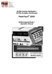
1
2
3
4
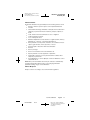
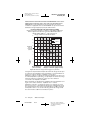
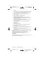
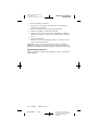
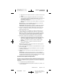
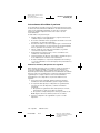
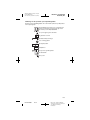
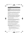
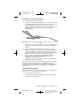
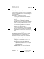
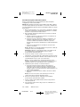
Sterile package opening instructions
1
MA16140A002
Rev A
Refer to the “Technical Manual”
category in doc# A00002 for Neuro
Core European Printing
Instructions.
3387-89OPN.fm 3/22/06 1:24 pm
UC200xxxxxx EN
4.3 x 8 inches (108 mm x 203 mm)
Medtronic Confidential
medvitld_R03
2
MA16140A002
Rev A
Refer to the “Technical Manual”
category in doc# A00002 for Neuro
Core European Printing
Instructions.
3387-89_SYM.fm 3/22/06 1:24 pm
UC200xxxxxx EN
4.3 x 8 inches (108 mm x 203 mm)
Medtronic Confidential
medvitld_R03
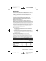
Explanation of symbols on package labeling
Refer to the package label to see which symbols apply to this product
Conformité Européenne (European Conformity). This
symbol means that the device fully complies with
European Directive 90/385/EEC.
Caution: Consult accompanying documents
Use by
STERILE EO
Sterilization: Ethylene oxide gas
Non reusable
+XX °C
+XXX °F
-XX °C
-XX °F
LOT
L E A D
Storage temperature
Lot number
Lead length
Manufacturing date
Open here
3
MA16140A002
Rev A
Refer to the “Technical Manual”
category in doc# A00002 for Neuro
Core European Printing
Instructions.
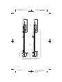
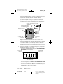
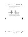
16.6 mm
2
1
0
2 mm (4X)
3
Proximal
16.6 mm
40 mm
3
2
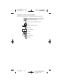
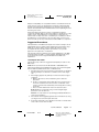
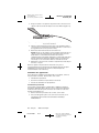
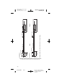
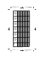
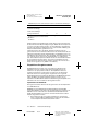
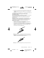
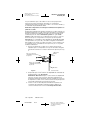
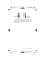
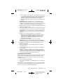
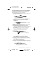
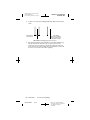
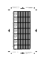
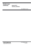
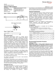
Note: Both Models 3387 and 3389 are available in 28-cm lengths
12.1 mm
10.6 mm
2
1
0
1.5 mm
3
Ø 1.27 mm (8x)
1.5 mm (3x)
1.5 mm
(4x)
Model 3387
9.0 mm
7.5 mm
2 3
1.5 mm
0 1
1.5 mm 0.5 mm
(4x)
(3x)
Model 3389
Ø 1.27 mm (8x)
Distal
3
Ø 1.27 mm
Ø 1.27 mm
0
1
2 mm (4X)
40 mm
Medtronic Confidential
medvitld_R03
3387-89_SYM.fm 3/22/06 1:24 pm
UC200xxxxxx EN
4.3 x 8 inches (108 mm x 203 mm)
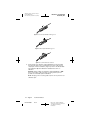
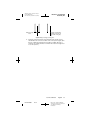
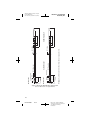
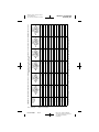
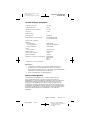
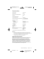
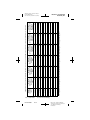
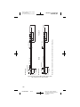
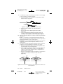
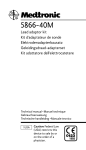
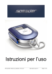
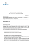
Figure A. Model Model 3389 and 3387 DBS Leads.
All dimensions are approximate.
4
MA16140A002
Rev A
Refer to the “Technical Manual”
category in doc# A00002 for Neuro
Core European Printing
Instructions.
3387-89_SYM.fm 3/22/06 1:24 pm
UC200xxxxxx EN
4.3 x 8 inches (108 mm x 203 mm)
Medtronic Confidential
medvitld_R03
The following are trademarks of Medtronic, Inc.: Activa®, DBS™, Itrel® II,
Medtronic®, PERCUPASS® II, and Soletra®.
5
MA16140A002
Rev A
Refer to the “Technical Manual”
category in doc# A00002 for Neuro
Core European Printing
Instructions.
3387-89_SYM.fm 3/22/06 1:24 pm
UC200xxxxxx EN
4.3 x 8 inches (108 mm x 203 mm)
Medtronic Confidential
medvitld_R03
6
MA16140A002
Rev A
Refer to the “Technical Manual”
category in doc# A00002 for Neuro
Core European Printing
Instructions.
Medtronic Confidential
medvitld_R03
3387-89TOC.fm 3/22/06 1:24 pm
UC200xxxxxx EN
4.3 x 8 inches (108 mm x 203 mm)
Table of contents
Introduction 9
Contents of sterile package 9
Indications 9
Contraindications 10
Warnings 10
Precautions 13
Electromagnetic Interference (EMI)
Adverse Events 17
Device Disposal 17
Resterilization
16
18
Suggested Procedures 19
Lead Implant Procedure 19
Intraoperative Stimulation Test 20
Stylet Removal and Lead Stabilization 25
Capping the Lead 28
Extended Test Stimulation 29
Programming Stimulation Parameters 32
Physician Instructions to Patient 34
Theft Detectors and Screening Devices
Specifications
34
36
General Warning
36
Technical Manual
MA16140A002
Rev A
English
7
Refer to the “Technical Manual”
category in doc# A00002 for Neuro
Core European Printing
Instructions.
3387-89TOC.fm 3/22/06 1:24 pm
UC200xxxxxx EN
4.3 x 8 inches (108 mm x 203 mm)
8
English
MA16140A002
Medtronic Confidential
medvitld_R03
Technical Manual
Rev A
Refer to the “Technical Manual”
category in doc# A00002 for Neuro
Core European Printing
Instructions.
3387-89_CH.fm 3/22/06 1:24 pm
UC200xxxxxx EN
4.3 x 8 inches (108 mm x 203 mm)
Medtronic Confidential
medvitld_R03
Introduction
The Medtronic Activa System is an implantable, multiprogrammable
quadripolar system that delivers electrical stimulation to selected areas of
the brain.
The Medtronic Model 3387 and 3389 DBS Leads are designed to
electrically stimulate specific areas of the brain (deep brain stimulation).
The Model 3387 DBS lead features wide (1.5 mm) spacing between each
of the four electrodes at the distal end. The Model 3389 DBS lead features
narrow (0.5 mm) spacing between each of the four electrodes at the distal
end.
Contents of sterile package
The Medtronic DBS Lead Kit consists of the following:
Lead:
■
One Model 3387 or 3389 Lead
Accessories:
■
Straight stylet (inserted in lead)
■
Hex wrench
■
Short stylet
■
Screening cables
– Alligator clip screening cable
– Twist-lock screening cable
■
Depth stop gauge
■
Burr hole ring and cap
■
Connector boot
■
Stainless steel PERCUPASS II Tunneling Tool and Tunneling Tip
■
Fluoropolymer tubes (straws)
■
Lead Cap
Note: All materials used in the Medtronic Model 3387 or 3389 DBS Lead
have been selected for biocompatibility through laboratory testing, animal
testing, and clinical experience. All accessories contained in the Medtronic
Model 3387 or 3389 DBS Lead Kit are intended for SINGLE USE ONLY.
Indications
The DBS System is indicated as a therapy for patients with disabling tremor
or symptoms of Parkinson’s disease. Recent studies have shown that deep
brain stimulation is effective in controlling Essential Tremor and the
symptoms of Parkinson’s disease which are not adequately controlled with
medications. Additionally, deep brain stimulation is effective in controlling
dyskinesias and fluctuations associated with medical therapy for
Parkinson’s disease.
Technical Manual
MA16140A002
Rev A
English
9
Refer to the “Technical Manual”
category in doc# A00002 for Neuro
Core European Printing
Instructions.
3387-89_CH.fm 3/22/06 1:24 pm
UC200xxxxxx EN
4.3 x 8 inches (108 mm x 203 mm)
Medtronic Confidential
medvitld_R03
Contraindications
Implantation of an Activa Brain Stimulation System is contraindicated for:
■
Patients exposed to diathermy. Do not use shortwave diathermy,
microwave diathermy or therapeutic ultrasound diathermy (all now
referred to as diathermy) on patients implanted with a
neurostimulation system. Energy from diathermy can be transferred
through the implanted system and can cause tissue damage at the
location of the implanted electrodes, resulting in severe injury or
death.
Diathermy is further prohibited because it can also damage the
neurostimulation system components resulting in loss of therapy,
requiring additional surgery for system explantation and
replacement. Injury or damage can occur during diathermy treatment
whether the neurostimulation system is turned “on” or “off.” Advise
your patients to inform all their health care professionals that they
should not be exposed to diathermy treatment.
■
Patients who will be exposed to Magnetic Resonance Imaging (MRI)
using a full body transmit radio-frequency (RF) coil, a receive-only
head coil, or a head transmit coil that extends over the chest area.
Performing MRI with this equipment can cause tissue lesions from
component heating, especially at the lead electrodes, resulting in
serious and permanent injury including coma, paralysis or death.
Refer to the MRI guidelines manual packaged with this product for
comprehensive safety information and instructions.
■
Patients for whom test stimulation is unsuccessful.
■
Patients who are unable to properly operate the system.
Warnings
Anticoagulants – Use extreme care with lead implantation in patients with
a heightened risk of intracranial hemorrhage. Physicians should consider
underlying factors, such as previous neurological injury, or prescribed
medications (anticoagulants), that may predispose a patient to the risk of
bleeding.
Excessive Stimulation – There is a potential risk of tissue damage at high
amplitudes and pulse widths. Stimulation parameter ranges for symptom
suppression are typically within 1 to 4 V. (amplitude), 60 to 180 µsecs
(pulse width), and 130 to 185 Hz (rate). Values above 7 V. and 250 µsecs
have rarely been used in clinical practice. High amplitudes and pulse widths
may indicate a system problem or less than optimal lead placement.
Parameter values exceeding the recommended ranges should only be
programmed with due consideration of the guidelines concerning charge
density described in the section “Programming Stimulation Parameters” on
page 32.
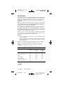
Charge Imbalance Condition (Soletra Model 7426 and Itrel II Model
7424 Neurostimulators) – Certain neurostimulator stimulation parameter
settings can produce a charge imbalance condition, in which the circuit
does not recover the total negative charge that is produced by device ON
activations. If the charge imbalance (net DC current) exceeds 1.5 µamps
average current, tissue damage may occur.
10
English
MA16140A002
Technical Manual
Rev A
Refer to the “Technical Manual”
category in doc# A00002 for Neuro
Core European Printing
Instructions.
3387-89_CH.fm 3/22/06 1:24 pm
UC200xxxxxx EN
4.3 x 8 inches (108 mm x 203 mm)
Medtronic Confidential
medvitld_R03
To avoid this condition, do not program the Soletra Model 7426 or the Itrel
II Model 7424 Neurostimulator to Cycling Mode or Special Ramp
Stimulation Mode for deep brain stimulation therapies. The programmer will
display a warning if either Cycling Mode or Special Ramp Stimulation Mode
is selected. For additional information, contact Medtronic.
When programming the neurostimulator using the SoftStart/Stop feature,
refer to Table 1 for aid in programming therapy stimulation. Check the
amplitude setting and the pulse width setting. The neurostimulator should
not exceed the number of activations listed for the selected parameters. An
activation occurs when the neurostimulator is turned ON and OFF by either
the patient magnet or the programmer.
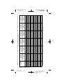
More than 50,000 activations in a 24-hour period would be required to
generate a charge imbalance condition using typical settings for symptom
suppression (frequency = 185 Hz, amplitude = 3.0 V, and pulse width =
90 µsec). A patient typically turns their neurostimulator ON in the morning,
and OFF at night; this counts as one device activation.
Technical Manual
MA16140A002
Rev A
English
11
Refer to the “Technical Manual”
category in doc# A00002 for Neuro
Core European Printing
Instructions.
12
English
MA16140A002
a
Rev A
101,000
81,000
54,000
54,000
29,000
22,000
16,000
14,000
12,000
10,000
8,800
7,900
7,600
6,700
1.1-2.0
2.1-3.0
3.1-3.6
3.7-4.0
4.1-5.0
5.2-6.0
6.1-6.5
6.7-7.2
7.4-8.0
8.2-9.0
9.1-9.5
9.7-10.0
10.1-10.5
3,100
3,500
4,000
4,600
6,200
6,600
7,800
8,900
13,000
16,000
30,000
50,000
50,000
73,000
135,000
Device Activation
Per 24 Hour Period
Programmed
Pulse Width
90 µsec
1,500
1,800
2,100
2,500
3,200
3,500
5,000
5,500
8,300
12,000
19,000
32,000
50,000
73,000
135,000
Device Activation
Per 24 Hour Period
Programmed
Pulse Width
120 µsec
260
330
430
570
840
840
1,200
1,600
2,500
5,000
5,600
7,600
17,000
32,000
135,000
Device Activation
Per 24 Hour Period
Programmed
Pulse Width
150-210 µsec
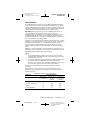
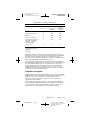
An activation occurs when the neurostimulator is turned On and Off by either the patient magnet or the programmer.
135,000
0.2-1.0
Device Activation
Per 24 Hour Period
Programmed
Pulse Width
60 µsec
0.0-0.1
Programmed
Amplitude
(volts)
110
130
160
200
240
240
380
580
1,100
2,200
2,200
3,200
6,500
23,000
135,000
Device Activation
Per 24 Hour Period
Programmed
Pulse Width
270-330 µsec
90
100
110
120
140
140
200
300
600
1,000
1,000
1,800
4,200
13,000
81,000
Device Activation
Per 24 Hour Period
Programmed
Pulse Width
400-450 µsec
Table 1. Maximum Allowable Device Activationsa Per 24-Hour Period. (For all programmable rates and electrode combinations, SoftStart ON)
3387-89_CH.fm 3/22/06 1:24 pm
UC200xxxxxx EN
4.3 x 8 inches (108 mm x 203 mm)
Medtronic Confidential
medvitld_R03
Technical Manual
Refer to the “Technical Manual”
category in doc# A00002 for Neuro
Core European Printing
Instructions.
3387-89_CH.fm 3/22/06 1:24 pm
UC200xxxxxx EN
4.3 x 8 inches (108 mm x 203 mm)
Medtronic Confidential
medvitld_R03
Magnetic Resonance Imaging – Do not conduct an MRI examination on
a patient with any implanted Activa System component until you read and
fully understand all MRI information in this manual. Do not conduct an MRI
examination at parameters other than those described in this guideline.
Failure to follow all warnings and guidelines related to MRI can result in
serious and permanent injury including coma, paralysis, or death. Refer to
the MRI guidelines manual packaged with this product for comprehensive
safety information and instructions.
Patient Activities – Close proximity to high levels of electromagnetic
interference (EMI) may cause a neurostimulator to switch ON or OFF. The
system also may unexpectedly cease to function due to normal battery
depletion or other causes. For these reasons, the patient should be advised
about any hazardous activities that would be potentially unsafe if their
movement disorder unexpectedly returns.
Pediatric Use – Safety and effectiveness has not been established for
pediatric use.
Placement of Lead-Extension Connector – The safety and
effectiveness of neck placement of the connector between the lead and
extension has not been established and has been associated with an
increased incidence of lead fracture.
Pregnancy – Safety for use during pregnancy or delivery have not been
established.
Theft Detectors and Screening Devices – Theft detectors found in retail
stores, public libraries, etc., and airport/security screening devices may
cause the stimulation power source of an implantable neurostimulation
system to switch On or Off. It is also possible that sensitive patients, or
those with low stimulation thresholds, may experience a momentary
increase in their perceived stimulation. For other indications, higher levels
of stimulation have been described as uncomfortable (“jolting” or
“shocking”) by some patients as they pass through these devices. Refer to
“Physician Instructions to Patient” on page 34 for more information.
Precautions
Storage and Sterilization
Resterilization Considerations – Refer to “Resterilization” on page 18
for further information.
Storage Temperature – Store the DBS Lead between –34 °C (0 °F) and
57 °C (135 °F). Temperatures outside this range can damage components.
System and Therapy
Component Failures – The physician should be aware that all
neurostimulation systems may unexpectedly cease to function. A system
may fail at any time due to random failures of the system components or
the battery (prior to normal depletion). These events, which can include
electrical short or open circuits and insulation breaches, cannot be
predicted.
Components – The use of non-Medtronic components with this system
may result in damage to Medtronic components, loss of stimulation, or
patient injury.
Technical Manual
MA16140A002
Rev A
English
13
Refer to the “Technical Manual”
category in doc# A00002 for Neuro
Core European Printing
Instructions.
3387-89_CH.fm 3/22/06 1:24 pm
UC200xxxxxx EN
4.3 x 8 inches (108 mm x 203 mm)
Medtronic Confidential
medvitld_R03
Inadvertent Programming – If more than one neurostimulator is
implanted, then the potential for unintentional programming changes to the
other neurostimulator exists. If two neurostimulators are implanted, they
must be implanted at least 20 cm (8 inches) apart to minimize interference.
Verify final programmed parameters by reviewing both devices at the
conclusion of any programming session.
Patient Magnet – The magnet provided to the patient for device activation
and deactivation may damage televisions, computer disks, credit cards,
and other items affected by strong magnetic fields.
Patient Management – To help ensure maximum benefits from the
neurostimulation system, long-term postsurgical management of patients
is recommended.
Programming Different Neurostimulator Models – The Model 7432
Clinician Programmer must be turned off and turned back on before
attempting to program a different neurostimulator model (for example, if
programming a Soletra Model 7426 neurostimulator immediately after
programming an Itrel II Model 7424 neurostimulator). If the programmer is
not turned off and on, the programmer will display “NO TELEMETRY,
POSITION HEAD AND TRY AGAIN” and the software will not allow the
different neurostimulator to be programmed.
Implantation / Explantation
Case Damage – If the neurostimulator case is ruptured or pierced after
implant due to outside forces, severe burns could result from exposure to
battery chemicals.
Component Disposal – If explanting a system component, please
remember the following guidelines:
■
Do not incinerate a neurostimulator; explosion can result if a
neurostimulator is subjected to incineration or cremation
temperatures.
■
Return all explanted components to Medtronic for analysis and safe
disposal.
Connections – Wipe off any body fluids from the lead contacts or
connector before making connections. Contamination of connections can
affect neurostimulation.
Etched Identification – Place the neurostimulator with the etched
identification side facing outward, away from the muscle layer of the body.
This helps to minimize the possibility of skeletal muscle stimulation that
may be perceived as twitching or burning.
Handling Components – Handle the implanted components of this
system with extreme care. These components may be damaged by
excessive traction or sharp instruments.
14
■
Do not bend, kink, or stretch the lead body whether or not the stylet
is in place. Do not bend or kink the tungsten stylet.
■
Do not tie a suture directly to the extension or lead body. Use the burr
hole cap and ring provided by Medtronic to secure the lead in place.
■
When handling the lead with forceps, use only a rubber-tipped
bayonet forceps.
■
Be extremely careful when using sharp instruments around the lead
to avoid nicking or damaging the lead body insulation.
English
MA16140A002
Technical Manual
Rev A
Refer to the “Technical Manual”
category in doc# A00002 for Neuro
Core European Printing
Instructions.
3387-89_CH.fm 3/22/06 1:24 pm
UC200xxxxxx EN
4.3 x 8 inches (108 mm x 203 mm)
Medtronic Confidential
medvitld_R03
Implant Considerations – Do not implant a component of the system
when:
■
The storage package has been pierced or altered; or if the
component shows signs of damage; or
■
The “Use By” date has expired, because this can adversely affect
storage package sterility.
Medical Environment
Most routine diagnostic procedures, such as fluoroscopy and x-rays, are
not expected to affect system operation. However, the following
precautions should be noted.
Effects on Other Medical Devices – The neurostimulation system may
affect the operation of other implanted devices, such as cardiac
pacemakers and implantable defibrillators. Possible effects include sensing
problems and inappropriate device responses. If the patient requires
concurrent implantable pacemaker and/or defibrillator therapy, careful
programming of each system may be necessary to optimize the patient’s
benefit from each device.
Electrocautery – Electrocautery can cause temporary suppression of
neurostimulator output and/or reprogramming of the neurostimulator. If use
of electrocautery is necessary, the current path (ground plate) should be
kept as far away from the neurostimulator and lead as possible. The use of
bipolar cautery is recommended.
External Defibrillators – Safety for use of external defibrillatory
discharges on patients with neurostimulation systems has not been
established. External defibrillation may damage a neurostimulator.
If external defibrillation is necessary and the situation permits, follow these
precautions to minimize current flowing through the neurostimulator and
lead-extension system:
■
Position defibrillation paddles as far from the neurostimulator as
possible.
■
Position defibrillation paddles perpendicular to the implanted
neurostimulator-lead system.
■
Use the lowest clinically appropriate energy output (watt seconds).
■
Confirm neurostimulation system function following any external
defibrillation.
High Radiation Sources – High radiation sources, such as cobalt 60 or
gamma radiation, should not be directed at the neurostimulator. If a patient
requires radiation therapy in the vicinity of the neurostimulator, place lead
shielding over the device to prevent radiation damage.
Lithotripsy – Use of high output ultrasonic devices, such as an
electrohydraulic lithotriptor, is not recommended for patients with an
implanted neurostimulation system. While there is no danger to the patient,
exposure to high output ultrasonic frequencies may result in damage to the
neurostimulator circuitry. If lithotripsy must be used, do not focus the beam
near the neurostimulator.
Technical Manual
MA16140A002
Rev A
English
15
Refer to the “Technical Manual”
category in doc# A00002 for Neuro
Core European Printing
Instructions.
3387-89_CH.fm 3/22/06 1:24 pm
UC200xxxxxx EN
4.3 x 8 inches (108 mm x 203 mm)
Medtronic Confidential
medvitld_R03
Electromagnetic Interference (EMI)
Electromagnetic interference is a field (electrical, magnetic or a
combination of both) that is generated by various medical or environmental
devices. These medical and environmental (home, occupational, and
other) devices may generate enough interference to change the
parameters of a neurostimulator; turn a neurostimulator off and on, or
cause a neurostimulator to surge, shock, or jolt the patient.
In addition, it is possible for the extension, lead or both to “pick up”
electromagnetic interference and deliver an excess voltage, which can in
turn deliver an excessive amount of heat to the brain. Refer to the following
sections for guidelines on the interaction of electromagnetic interference
and an implanted Activa System.
Psychotherapeutic Procedures – The safety of psychotherapeutic
procedures using equipment that generates electromagnetic interference
(e.g., electroshock therapy, transcranial magnetic stimulation) has not been
established.
Home or Occupational Environment
Home Appliances – Home appliances that are in good working order and
properly grounded do not usually produce enough electromagnetic
interference (EMI) to interfere with neurostimulator operation. However,
items with magnets (e.g., stereo speakers, refrigerators, freezers) may
cause the neurostimulator to switch On or Off.
Occupational Environments – Commercial electrical equipment (arc
welders, induction furnaces, resistance welders), communication
equipment (microwave transmitters, linear power amplifiers, high-power
amateur transmitters), and high voltage power lines may generate enough
electromagnetic interference (EMI) to interfere with neurostimulator
operation if approached too closely.
Patient Activities/Environmental Precautions – Patients should
exercise reasonable caution in avoidance of devices which generate a
strong electric or magnetic field. Close proximity to high levels of
electromagnetic interference (EMI) may cause a neurostimulator to switch
On or Off. The system also may unexpectedly cease to function due to
battery depletion or other causes. For these reasons, the patient should be
advised about any activities that would be potentially unsafe if their
symptoms unexpectedly return. For additional information about devices
which generate electromagnetic interference, contact your local Medtronic
representative.
Patient Magnet – The magnet provided to the patient for device activation
and deactivation may damage televisions, computer disks, computer
monitors, credit cards, and other items affected by strong magnetic fields.
Radio Frequency Sources – Analog and digital cellular phones, AM/FM
radios, cordless phones, and conventional wired telephones may contain
permanent magnets. To prevent undesired turning On or Off of the
stimulation, these devices should be kept at least 10 cm away from the
implanted neurostimulator.
Therapeutic Magnets – Therapeutic magnets (for example, those found
in bracelets, back braces, shoe inserts and mattress pads) can cause
inadvertent on or off activations of the neurostimulator. Therefore, patients
should be advised not to use them.
16
English
MA16140A002
Technical Manual
Rev A
Refer to the “Technical Manual”
category in doc# A00002 for Neuro
Core European Printing
Instructions.
3387-89_CH.fm 3/22/06 1:24 pm
UC200xxxxxx EN
4.3 x 8 inches (108 mm x 203 mm)
Medtronic Confidential
medvitld_R03
Adverse Events
Deep brain stimulation may potentially have the following adverse events:
■
Allergic or immune system response to the implanted materials
■
Infection
■
Intracranial hemorrhage, immediate or delayed, which could result in
temporary or permanent muscle weakness, paralysis, aphasia, or
death
■
Lead, extension and neurostimulator erosion or migration
■
Lead and extension fracture
■
Loss of therapeutic effect
■
Mentation impairment such as attention or cognitive deficits, memory
disturbances, confusion, or psychiatric disturbances
■
Motor problems such as paresis, weakness, incoordination, muscle
spasms, gait disorders, tremor, dystonia, or chorea
■
Persistent pain or discomfort with neurostimulation
■
Seizures
■
Sensory changes
■
Seroma or hematoma at the neurostimulator site
■
Speech problems such as dysphasia or dysarthria
■
Undesirable sensations such as paresthesia that could be either
temporary or permanent
■
Visual disturbances, such as diplopia, oculomotor difficulties or other
visual field effects
Note: Many of the undesirable effects may be reduced or eliminated by
changing lead position during surgery, or by changing stimulation
parameters during surgery or test stimulation.
Device Disposal
Dispose of device according to local environmental regulations.
Technical Manual
MA16140A002
Rev A
English
17
Refer to the “Technical Manual”
category in doc# A00002 for Neuro
Core European Printing
Instructions.
Medtronic Confidential
medvitld_R03
3387-89_CH.fm 3/22/06 1:24 pm
UC200xxxxxx EN
4.3 x 8 inches (108 mm x 203 mm)
Resterilization
The lead and accessories of the DBS Lead Kit were sterilized with ethylene
oxide before shipment. Inspect the sterile package for seal integrity and
damage before opening and using the contents. If you are unsure of the
components’ sterility for any reason, they should be resterilized at the
hospital site.
Note: If contamination is suspected because of a defective sterile package
seal, leads and accessories can be returned to Medtronic for replacement
or they can be resterilized at the hospital. Medtronic does not accept
returned leads or accessories for resterilization.
Due to variations in hospital sterilizers, precise instructions for sterilization
or aeration cannot be given here. If further information is necessary
regarding procedures to be used, contact the manufacturer of the sterilizer
unit. Use biological indicators or other acceptable method to validate the
effectiveness of the hospital’s sterilizer unit.
Medtronic cannot accept the responsibility for the hospital’s resterilization
of any components. If, however, the hospital decides to resterilize, usual
and customary sterilization methods should be used.
Cautions:
■
Do not resterilize and use lead or accessories after exposure to body
tissues or fluids.
■
Do not use radiation to resterilize any component. Do not autoclave
lead, percutaneous extension, stylet, burr hole ring/cap, connector
boot, or lead cap.
Subject to the foregoing, the following suggestions may be considered:
Table 2 is a summary of the applicable resterilization options and
restrictions. The paragraphs following the table provide additional
information.
Table 2. Resterilization Options and Restrictions
Sterilization methodsa
Component
Lead
Ethylene Oxide
55 oC Maximum
Autoclave
121 oC 103 kPa
30 minutes
“Flash”
Autoclave
132 oC 186 kPa
5 minutes
YES
NO
NO
Percutaneous extension
YES
NO
NO
Stylet
YES
NO
NO
Screening cable
YES
YESb
YESc
Burr hole ring/cap;
connector boot, lead cap
YES
NO
NO
Other accessories
YES
YES
YES
a
b
c
Medtronic cannot accept the responsibility for the hospital’s resterilization of any
components.
60 minutes
30 minutes
18
English
MA16140A002
Technical Manual
Rev A
Refer to the “Technical Manual”
category in doc# A00002 for Neuro
Core European Printing
Instructions.
3387-89_CH.fm 3/22/06 1:24 pm
UC200xxxxxx EN
4.3 x 8 inches (108 mm x 203 mm)
Medtronic Confidential
medvitld_R03
Ethylene oxide (ETO) is an acceptable method for resterilization when the
leads and accessories are repackaged in an ethylene oxide-permeable
package. The temperature during the process should not exceed 55 °C.
Allow for the maximum aeration of ETO residues before implanting the lead
and using accessories.
Steam autoclaving may also be used as a sterilization method for
components marked “YES” for autoclave in Table 2. A standard cycle of 30
minutes at 121 °C and 103 kPa is recommended. If components are
marked “YES” for “flash” autoclave, a standard cycle of 5 minutes at 132 °C
and 186 kPa is recommended. For the screening cable, use the longer
times noted. Do not use any method that is marked “NO” for a component.
Suggested Procedures
The implantation of the DBS Lead requires stereotactic techniques for the
initial implant and close patient follow-up during the postoperative stage.
Medtronic recognizes that a variety of approaches may be used to
accomplish this. The following outline is presented as one possible
approach for the physician’s consideration.
The target site may be localized for stereotactic implantation of the DBS
Lead using CT Scans, MRI, or ventriculography. Stimulation with a test
electrode may be used for target identification before DBS Lead
implantation.
Lead Implant Procedure
The following steps outline the suggested lead implant procedure for the
DBS Lead.
Caution: The stylet inserted in the Model 3387 or 3389 DBS lead is
matched specifically to that individual lead; stylets are not interchangeable
between 3387 and 3389 lead models or individual leads.
1. After placement of the stereotactic frame on the patient, use standard
imaging techniques to determine coordinates for the lead’s target
site.
2. After imaging, prepare the patient per normal stereotactic surgical
techniques.
a. Make a skin incision, with consideration given to burr hole
placement.
b. Prepare a sub-galeal pocket by blunt dissection for placement of
the excess lead wire and connector. Give consideration to the
location of the burr hole and laterality of the therapy when creating
the pocket.
c. Place a 14 mm diameter burr hole in the desired location.
Note: Medtronic recommends using a 14 mm straight-edged
perforator to form the burr hole.
Caution: Use only a burr hole cap and ring provided by Medtronic to
secure the lead in place.
3. Place the burr hole ring tightly against the bone in the burr hole, using
your finger and a curved mosquito hemostat.
4. Position the guide tube or the collimator in the frame so that its distal
end is 1.25 to 2.5 cm from the skull.
Technical Manual
MA16140A002
Rev A
English
19
Refer to the “Technical Manual”
category in doc# A00002 for Neuro
Core European Printing
Instructions.
3387-89_CH.fm 3/22/06 1:24 pm
UC200xxxxxx EN
4.3 x 8 inches (108 mm x 203 mm)
Medtronic Confidential
medvitld_R03
Note: If an insertion cannula and stylet are used, the cannula should
be placed to a point approximately 10 mm proximal to the target site
for stimulation.
5. Determine target location with a test electrode.
a. Place the test electrode 10 mm above target. Slowly and
delicately advance it 1 mm at a time and test stimulate. Maximum
therapeutic effect with minimum side effects indicate the
appropriate target.
b. Once target is determined, document the location.
Note: It may be necessary to make additional tracks to achieve
optimum lead placement.
6. Remove the test electrode. Determine the depth of placement for the
DBS Lead.
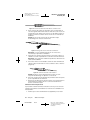
7. Attach the lead depth stop gauge on the lead at the point calculated
in step 6.
8. Advance the lead along the track made by the test electrode.
Caution: An increase in resistance or friction during lead insertion
may indicate that the lead is deviating from the intended track. If this
occurs, pull the lead back and re-advance until target is reached.
Intraoperative Stimulation Test
This section outlines the intraoperative stimulation test that helps confirm
the desired lead position for optimum symptom suppression. This test
requires the following components:
■
A Model 3625 Test Stimulator
■
An alligator clip or twist-lock screening cable.
The procedures outlined in this section provide instructions for test
stimulation with the alligator clip or twist-lock screening cable and the
Model 3625 Test Stimulator.
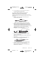
Test Stimulation with the Alligator Clip Screening Cable
The alligator clip screening cable is bipolar. The polarity of the black
alligator clip is controlled by Electrode Switch ‘0’, and the red alligator clip
is controlled by Electrode Switch ‘3’. Electrode Switches ‘1’ and ‘2’ are
inactive. Use the alligator clips to select the lead contacts that correspond
to the electrodes you want to test.
Caution: The switches on the 3625 Test Stimulator corresponding to
electrodes ‘0’ and ‘3’ must be manually set to establish a circuit. One switch
must be positive and the other switch negative. If the ‘0’ and ‘3’ electrode
switches are not set accordingly, no stimulation will result.
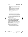
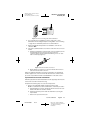
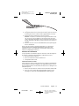
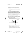
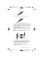
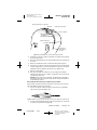
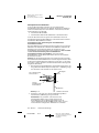
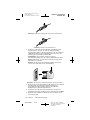
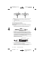
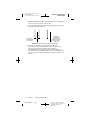
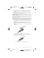
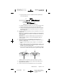
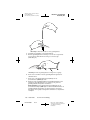
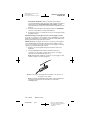
1. Attach the alligator clips to the applicable lead contacts that
correspond to the desired electrodes — Figure 1 illustrates the
connection to the lead contacts for electrodes 0 and 3.
20
English
MA16140A002
Technical Manual
Rev A
Refer to the “Technical Manual”
category in doc# A00002 for Neuro
Core European Printing
Instructions.
Medtronic Confidential
medvitld_R03
3387-89_CH.fm 3/22/06 1:24 pm
UC200xxxxxx EN
4.3 x 8 inches (108 mm x 203 mm)
Stylet handle
Red: Connects to
Electrode Select Switch 3
Proximal
3
2
1
0
Black: Connects to
Electrode Select Switch 0
Distal
Lead
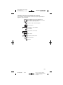
Figure 1. Connect clips to lead contacts.
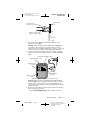
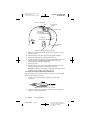
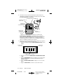
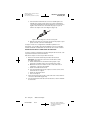
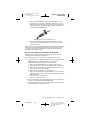
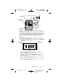
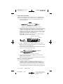
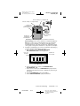
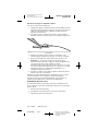
2. Check that the test stimulator External A–amplitude control
(Figure 2) is turned OFF.
Warning: Always turn External A–amplitude Control OFF before
connecting or disconnecting the screening cable from the test
stimulator, or before changing alligator clip connections to the lead
contacts to prevent possible uncomfortable patient stimulation.
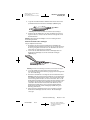
3. Push the screening cable plug into the test stimulator receptacle
(Figure 2). Note the correct plug orientation — it fits in one way
only.
External A – Amplitude control
External R – Rate control
Internal controls
cover latch
Cable plug
Test stimulator
receptacle
Battery cover
latch
Figure 2. Model 3625 Test Stimulator External Controls.
Warning: Always turn the test stimulator External A–amplitude
Control to OFF before connecting or disconnecting the screening
cable from the test stimulator, or before changing alligator clip
connections or Internal Controls to prevent possible uncomfortable
patient stimulation.
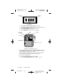
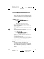
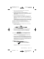
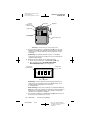
4. Remove the Internal Control Cover (Figure 2) and set the Internal
Controls (Figure 3) as follows:
a. Set the ELECTRODE SELECT switch polarities as shown.
Technical Manual
MA16140A002
Rev A
English
21
Refer to the “Technical Manual”
category in doc# A00002 for Neuro
Core European Printing
Instructions.
Medtronic Confidential
medvitld_R03
3387-89_CH.fm 3/22/06 1:25 pm
UC200xxxxxx EN
4.3 x 8 inches (108 mm x 203 mm)
Black clip’s
polarity
Red clip’s
polarity
ELECTRODE SELECT
+
+
+
OFF
OFF
OFF
_
0
_
1
_
2
3
OFF–not used
b. Set the RATE and Pulse Width Select switch to B.
c. Set the External RATE to 130 Hz, or as desired (therapeutic range
is 130–185 Hz). Do not exceed 185 Hz.
d. Set the PULSE WIDTH to 60 µsec, or as desired.
e. Set the AMP LIMIT control to 10 V, or as desired.
Rate
Rate and
Pulse Width
select
Amplitude
Pulse width
Amp limit
Electrode select
Figure 3. Set Internal/External Controls.
5. Turn the External A–amplitude Control ON and gradually increase it
until the patient indicates an effect, or until a stimulation effect such
as the suppression of symptoms is noted.
Note: The optimal stimulation effect is an obvious improvement in
motor symptoms with minimal undesirable side effects.
6. To reverse the output polarity:
a. Set the External A–amplitude Control to OFF.
b. Set the ELECTRODE SELECT switch polarities as shown.
22
English
MA16140A002
Technical Manual
Rev A
Refer to the “Technical Manual”
category in doc# A00002 for Neuro
Core European Printing
Instructions.
Medtronic Confidential
medvitld_R03
3387-89_CH.fm 3/22/06 1:25 pm
UC200xxxxxx EN
4.3 x 8 inches (108 mm x 203 mm)
Black clip’s
polarity
ELECTRODE SELECT
+
+
+
OFF
OFF
OFF
_
0
_
1
Red clip’s
polarity
_
3
2
OFF–not used
Note: The output polarity can also be reversed by switching the
alligator clip-electrode contact connections.
c. Repeat step 5.
Warning: Always turn the test stimulator External A–amplitude
Control to OFF before changing ELECTRODE SELECT switches or
other Internal Controls to prevent possible uncomfortable patient
stimulation.
7. When the intraoperative testing is completed, turn the test
stimulator’s External A–amplitude Control to OFF.
8. Disconnect the screening cable alligator clips from the lead contacts.
Test Stimulation with the Twist-Lock Screening Cable
The twist-lock screening cable is quadripolar. When connected to the
Model 3625 Test Stimulator, all four Electrode Switches are active.
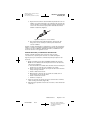
Caution: Before connecting the twist-lock screening cable to the stylet
handle of the DBS lead, secure the cable. Otherwise, the weight of the
twist-lock connector may cause lead movement.
1. Check that the test stimulator output (Amplitude) is off.
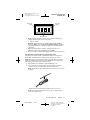
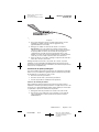
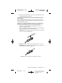
2. Insert and lock the stylet handle on the lead into the twist-lock
connector on the screening cable. (Refer to Figures 4–7).
Note: The handle fits into cylindrical twist connector in only one way
(Figure 4).
Figure 4. Position stylet handle and cylindrical twist-lock connector.
Note: Place the stylet handle into the groove at a slight angle to
secure the handle’s end.
Technical Manual
MA16140A002
Rev A
English
23
Refer to the “Technical Manual”
category in doc# A00002 for Neuro
Core European Printing
Instructions.
3387-89_CH.fm 3/22/06 1:25 pm
UC200xxxxxx EN
4.3 x 8 inches (108 mm x 203 mm)
Medtronic Confidential
medvitld_R03
Figure 5. Secure stylet handle’s end in groove.
Figure 6. Insert stylet handle into groove.
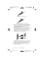
Figure 7. Lock the twist-lock connector.
3. Verify that the test stimulator output (Amplitude) is turned to OFF,
then push the plug on the test stimulator end of the cable into the
output jack of the test stimulator (Figure 8). Refer to the Model 3625
Test Stimulator Operator Manual for detailed instructions on
utilization.
Warning: Always adjust test stimulator output (Amplitude) to OFF
before connecting or disconnecting screening cable to prevent
possible uncomfortable patient stimulation.
Note: The plug of the screening cable only fits one way into the test
stimulator jack.
24
English
MA16140A002
Technical Manual
Rev A
Refer to the “Technical Manual”
category in doc# A00002 for Neuro
Core European Printing
Instructions.
Medtronic Confidential
medvitld_R03
3387-89_CH.fm 3/22/06 1:25 pm
UC200xxxxxx EN
4.3 x 8 inches (108 mm x 203 mm)
Figure 8. Connect screening cable and test stimulator.
4. Proceed with the test stimulation. Refer to steps 4–8 of “Test
Stimulation with the Alligator Clip Screening Cable” section starting
on page 20, for stimulation parameter recommendations.
5. When finished with intraoperative test stimulation, turn the test
stimulator OFF.
6. Unlock the cylindrical twist-lock connector and remove the connector
handle.
a. Hold the test stimulator end of the twist connector stationary in the
left hand and turn the lead end of the twist connector
counterclockwise with the right hand until the grooves on each
side are lined up (Figure 9).
Figure 9. Unlock the twist-lock connector.
b. Gently pull up on lead end of connector handle until it is free to
remove it from the twist connector.
When the optimum stimulation mode and configuration are determined,
and the suppression of the movement disorder has been achieved, then
proceed to “Stylet Removal and Lead Stabilization” in the next section.
Stylet Removal and Lead Stabilization
When the physician has determined that the lead is properly positioned, the
lead can be secured in the burr hole ring.
Complete the following steps to secure the lead position.
1. Remove the adjustable depth stop gauge from the lead.
Note: If a cannula was used for lead insertion, follow this procedure:
a. Carefully pull the insertion cannula up until the lead can be seen
between the burr hole and the cannula.
b. Hold the lead at the point it exits the skull while loosening the
stylet handle.
c. Remove the stylet from the lead.
Technical Manual
MA16140A002
Rev A
English
25
Refer to the “Technical Manual”
category in doc# A00002 for Neuro
Core European Printing
Instructions.
3387-89_CH.fm 3/22/06 1:25 pm
UC200xxxxxx EN
4.3 x 8 inches (108 mm x 203 mm)
Medtronic Confidential
medvitld_R03
d. While keeping that lead secure at the exit site, remove the lead
from the lead holder.
e. Remove the insertional cannula.
f. Proceed with step 5.
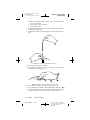
2. Hold the lead at the point that it exits the skull while loosening the
stylet handle (Figure 10).
3. Continuing to hold the lead at the skull, remove the stylet from the
lead.
Figure 10. Loosen the stylet handle from the lead.
4. Remove the guide tube or collimator.
5. Gently press the lead into one of the precut grooves on the inner side
of the burr hole ring (Figure 11).
Figure 11. Gently press the lead into the burr hole ring.
6. Recheck the stimulation effect after anchoring the lead.
7. Check that the test stimulator output (Amplitude) is adjusted to OFF.
8. If using the alligator clip screening cable, carefully attach the alligator
clips to the desired connector ring contacts on the lead end.
26
English
MA16140A002
Technical Manual
Rev A
Refer to the “Technical Manual”
category in doc# A00002 for Neuro
Core European Printing
Instructions.
Medtronic Confidential
medvitld_R03
3387-89_CH.fm 3/22/06 1:25 pm
UC200xxxxxx EN
4.3 x 8 inches (108 mm x 203 mm)
Warning: Always adjust test stimulator output (Amplitude) to OFF
when changing alligator clip connections to connector rings to
prevent possible uncomfortable patient stimulation.
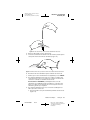
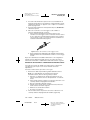
9. If using the twist-lock screening cable, complete the following steps:
a. Attach the enclosed short stylet to the proximal end of the lead
(Figure 12).
Figure 12. Attach short stylet to lead.
b. Insert the short stylet completely into the lead (Figure 12a).
c. Secure the lead in the stylet handle (Figure 12b).
d. Insert the stylet handle of the lead into the cylindrical twist-lock
connector on the screening cable and lock it (Refer to Figure 4–
Figure 7).
10. Turn on the test stimulator and recheck stimulation effects.
Note: If lead movement has occurred, it may be necessary to remove
lead and repeat the implant procedure, using a new lead.
Warning: If lead repositioning is required, do not reinsert stylet into
implanted lead. Use a new lead.
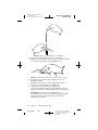
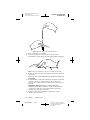
11. To minimize the potential for lead movement, place the burr hole cap
into the ring as follows:
a. Align the tab in the burr hole cap with the slot in the burr hole ring.
b. Hold the cap tilted toward the slot in the ring where the lead is
fixed, and gently press the cap against the edge of the burr hole
ring and lead (Figure 13a).
c. Gently press down on the center of the cap and roll the cap
downward into the ring until secure (Figure 13b).
a
b
Figure 13. Gently press burr hole cap into burr hole ring.
12. If a second lead is implanted, repeat the lead implant procedure.
13. Prepare the patient for implant of the neurostimulator.
Technical Manual
MA16140A002
Rev A
English
27
Refer to the “Technical Manual”
category in doc# A00002 for Neuro
Core European Printing
Instructions.
Medtronic Confidential
medvitld_R03
3387-89_CH.fm 3/22/06 1:25 pm
UC200xxxxxx EN
4.3 x 8 inches (108 mm x 203 mm)
Capping the Lead
If the remainder of the neurostimulation system is not implanted
immediately after lead implantation, perform the following steps:
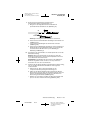
1. Push the connector boot over the exposed end of the lead
(Figure 14).
Figure 14. Push connector boot over lead.
2. Cover the exposed end of the lead with the lead cap contained in the
lead kit (Figure 15). Tighten the single setscrew in the setscrew
socket on the number 3 lead contact by turning it clockwise with the
hex wrench provided. Tighten the setscrew only until it touches the
contact. Continue tightening for a maximum of 1/4 turn only.
Caution: Excessive torque on setscrews may damage lead contact.
Lead Contact 3
Lead
Figure 15. Insert lead into lead cap.
3. Slide the connector boot into place over the lead cap.
Note: If it is difficult to position the boot, sterile water may be used as
a lubricant.
4. Place non-absorbable sutures in the channeled area around the
proximal end of the boot (Figure 16).
Figure 16. Suture lead/lead cap.
5. Place the lead in the subgaleal pocket, close the incision, and apply
the appropriate dressing.
Note: The lead cap is designed for temporary use only.
Removing the Lead Cap
For each implanted lead:
1. Locate the lead cap at the proximal end of the lead and make an
incision to expose it. Allow room to hold the lead firmly to prevent
dislodgement.
2. Cut the suture and the connector boot over the lead cap to expose
the setscrew (Figure 17).
28
English
MA16140A002
Technical Manual
Rev A
Refer to the “Technical Manual”
category in doc# A00002 for Neuro
Core European Printing
Instructions.
Medtronic Confidential
medvitld_R03
3387-89_CH.fm 3/22/06 1:25 pm
UC200xxxxxx EN
4.3 x 8 inches (108 mm x 203 mm)
Figure 17. Cut the suture and connector boot to expose setscrew.
3. Using the hex wrench, loosen the setscrew in the setscrew connector
by turning the wrench counterclockwise (approximately one turn).
4. Gently remove the lead from the setscrew connector.
Caution: If resistance is felt when removing the lead from the lead
cap, loosen the setscrew slightly to ensure that it clears the lead
contact. Avoid disengaging the setscrew. Inspect the lead contact for
damage (flattening or stretching of lead) if resistance was felt prior to
removal.
5. Hold the setscrew connector and withdraw the lead cap through the
incision and discard.
Remove the boot from the lead and discard the boot. If desired, the
neurostimulator may be implanted immediately following the lead
implantation. (Refer to the applicable neurostimulator and extension
manuals for implanting instructions.)
Extended Test Stimulation
If a postoperative test stimulation period is desired, use the following three
procedures for Extended Test Stimulation outlined in this section:
■
Create Percutaneous Tunnel
■
Connect Lead and Percutaneous Extension
■
Interoperative Test Period
Create Percutaneous Tunnel
The following procedure provides instructions for attaching and implanting
the percutaneous extension (available in the appropriate lead accessory
kit). The implanted wires should exit the skin above the ear during the test
stimulation period.
1. Remove the percutaneous extension from its tube. Discard this tube.
2. Place one of the shorter tubes packaged with the lead over the
tunneling tool. Attach the metal PERCUPASS II Tunneling Tip.
Technical Manual
MA16140A002
Rev A
English
29
Refer to the “Technical Manual”
category in doc# A00002 for Neuro
Core European Printing
Instructions.
Medtronic Confidential
medvitld_R03
3387-89_CH.fm 3/22/06 1:25 pm
UC200xxxxxx EN
4.3 x 8 inches (108 mm x 203 mm)
Burr hole cap and ring
Lead
Percutaneous
connector
50 mm pocket
Tube (remove
after tunneling
is completed)
Percutaneous
extension wires
Exit
Pin connector
handle
Figure 18. Tunneling and Lead Placement.
3. Make a small stab wound where the percutaneous extension wires
will exit the skin.
4. Tunnel subcutaneously from the pocket through the exit point.
5. Remove the tunneling tool, leaving the tube in place.
6. Pass the percutaneous extension wires through the tube. Leave only
the pin connector and approximately 40 mm of the fine wires
protruding from the exit point (Figure 18).
7. Remove the tube.
8. Coil the lead in a circle greater than 25 mm in diameter to prevent
bending or kinking. Place the coiled lead in the pocket.
Caution: Be extremely careful when using sharp instruments around
lead body to avoid nicking or damaging the lead.
Connecting the Lead and Percutaneous Extension
The following procedure provides instructions on how to connect the DBS
lead to the percutaneous extension.
1. Push the connector boot over the exposed end of the lead
(Figure 19).
Figure 19. Push connector boot over lead.
2. Insert the exposed end of the lead completely into the percutaneous
extension connector (Figure 20).
30
English
MA16140A002
Technical Manual
Rev A
Refer to the “Technical Manual”
category in doc# A00002 for Neuro
Core European Printing
Instructions.
3387-89_CH.fm 3/22/06 1:25 pm
UC200xxxxxx EN
4.3 x 8 inches (108 mm x 203 mm)
Medtronic Confidential
medvitld_R03
Figure 20. Insert lead fully into setscrew junction.
3. Tighten each of the four setscrews by turning them clockwise in the
setscrew sockets with the hex wrench provided (Figure 21). Tighten
the setscrews only until they touch the contacts. Continue tightening
for a maximum of 1/4 turn only.
Caution: Excessive torque on setscrews may damage lead contacts.
Figure 21. Tighten extension connector setscrews.
Note: The setscrews must engage contacts on lead before
stimulation can be attempted.
4. Slide the connector boot into place, completely covering the lead/
extension connection.
Note: If it is difficult to position boot, sterile water may be used as a
lubricant.
5. Place non-absorbable sutures around both ends of the boot in the
channeled areas of the connection (Figure 22).
Figure 22. Suture lead/extension
Caution: Do not overtighten suture because damage may occur to
either boot or lead.
6. Place the lead/percutaneous extension connection into a small
pocket made near the incision site.
7. Close the incision site and stab wound, leaving the fine percutaneous
extension wires and pin connector protruding from the skin.
Interoperative Stimulation Test
The following procedure provides instructions on how to connect the
percutaneous extension to the test stimulator and begin interoperative test
stimulation.
1. Check that the test stimulator output (Amplitude) is off.
2. Connect the pin connector on the percutaneous extension into the
twist-lock connector on the screening cable, and the plug end of the
cable to the Model 3625 Test Stimulator. Refer to “Test Stimulation
with the Twist-Lock Screening Cable” on page 23 for instructions on
connecting and disconnecting the twist-lock cable and the test
stimulator.
Technical Manual
MA16140A002
Rev A
English
31
Refer to the “Technical Manual”
category in doc# A00002 for Neuro
Core European Printing
Instructions.
3387-89_CH.fm 3/22/06 1:25 pm
UC200xxxxxx EN
4.3 x 8 inches (108 mm x 203 mm)
Medtronic Confidential
medvitld_R03
Note: Different electrode configurations should be evaluated at
various parameter settings (Rate, Amplitude, Pulse Width).
3. When finished with interoperative test stimulation, turn the test
stimulator OFF.
4. Unlock the cylindrical twist-lock connector and remove the connector
handle.
When the optimum stimulation mode and configuration are determined,
and the suppression of the movement disorder has been noted, proceed
with internalization of the remainder of the system.
When internalizing the neurostimulator, follow the instructions in the
appropriate neurostimulator and extension implant manuals.
Programming Stimulation Parameters
When programming stimulation parameters, give consideration to the
following recommendations regarding charge density.
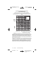
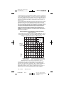
Charge Density
A survey of literature regarding electrical stimulation of neural tissue
suggests that damage may occur above 30 microcoulombs/cm 2/phase.
The neurostimulation system is capable of producing charge densities in
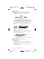
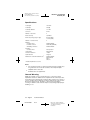
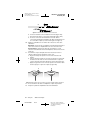
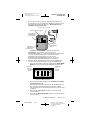
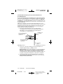
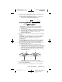
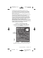
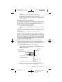
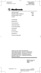
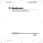
excess of 30 microcoulombs/cm2/phase (Figure 23).
The device’s maximum amplitude is 10.5 V, and maximum pulse width is
450 microseconds. The curved lines in Figure 23 represent a charge
density of 30 microcoulombs/cm2/phase at various impedance
measurements, calculated for the electrode surface area of the Model 3387
and Model 3389 DBS leads. Mean resistance found in the Tremor Clinical
Studies was 1348 Ω (610–2000 Ω).
Charge density is determined by plotting a point corresponding to the pulse
width setting (x-axis), and the amplitude setting (y-axis). If this point is
below the appropriate resistance curve, then the charge density is below
30 microcoulombs/cm2/phase. Points above the curve indicate a charge
density above 30 microcoulombs/cm2/phase.
The shaded area of Figure 23 indicates a charge density above
30 microcoulombs/cm2/ phase at the conservative impedance estimate of
500 ohms. If stimulation parameters are selected that fall into the shaded
area of the graph, the following programmer message appears:
“WARNING: CHARGE DENSITY MAY BE HIGH ENOUGH TO CAUSE
TISSUE DAMAGE. CONSULT TECH MANUAL. PRESS CLEAR TO
CONTINUE.” Programming may continue at the desired values by pressing
the CLEAR key. Refer to the appropriate Software Applications Manual for
further information.
32
English
MA16140A002
Technical Manual
Rev A
Refer to the “Technical Manual”
category in doc# A00002 for Neuro
Core European Printing
Instructions.
Medtronic Confidential
medvitld_R03
3387-89_CH.fm 3/22/06 1:25 pm
UC200xxxxxx EN
4.3 x 8 inches (108 mm x 203 mm)
DBS Amplitude and Pulse Width Limits
Computed for Resistances Ranging from 500 to 2,000 Ohms
Model 3387 and 3389 DBS Lead Electrode Surface Area = 0.06 cm2,
Charge Density Threshold = 30 Microcoulombs/cm2/phase
18
2,000 Ohms
16
1,348 Ohms*
500 Ohms
14
12
Max Device
Amplitude
(10.5V) 10
WARNING
AREA
8
Example B
+
6
4
Amplitude
(Volts)
Example A
+
2
0
0
50
100
Pulse Width
(Microseconds)
150
200
250
300
350
400
450
*Mean resistance from clinical
studies = 1348 ohms (range 610-2000)
Figure 23. Charge density at various parameter settings.
Figure 23 includes two examples of charge density calculated for the
neurostimulation system. In Example A, the neurostimulator is set to:
amplitude = 3.0 V and pulse width = 90 µsec. The charge density for
Example A is below the lowest impedance curve, thus indicating a charge
density below 30 microcoulombs/cm2/ phase at the most conservative
impedance of 500 Ω.
In Example B, neurostimulator stimulation parameters are set to: amplitude
= 6.1 V and pulse width = 210 µsec. The charge density at these settings
is in the shaded area indicating it may be high enough to cause tissue
damage at an impedance of 500 Ω. However, if the impedance in this case
is 1348 Ω, the charge density would be below 30 microcoulombs/cm2/
phase.
Technical Manual
MA16140A002
Rev A
English
33
Refer to the “Technical Manual”
category in doc# A00002 for Neuro
Core European Printing
Instructions.
Medtronic Confidential
medvitld_R03
3387-89_CH.fm 3/22/06 1:25 pm
UC200xxxxxx EN
4.3 x 8 inches (108 mm x 203 mm)
Physician Instructions to Patient
It is suggested that you give your patient information concerning the
Medtronic Neurostimulation System. This should include information on the
implanted neurostimulator, the lead, and the extension. Also provide your
patient with instructions on the use of the neurostimulator.
Patients should be instructed to:
■
Care for surgical wound and observe post-implant instructions.
■
Avoid physical activities which may damage the implant site or the
implanted device.
■
Consult his or her physician if they notice any unusual symptoms or
signs (e.g., pain, swelling, or skin erosion at the implant site;
dizziness or lightheadedness; movement problems or reduced
coordination).
■
Operate the neurostimulator control magnet; and how to properly
store the magnet after use.
■
Understand the potential side effects and risks of deep brain
stimulation.
■
Inform personal physicians, consulting physicians, or dentists that
they have an implanted neurostimulation system.
■
Advise your patient to avoid manipulating the implanted system
components (e.g., the neurostimulator, the burr hole site). This can
result in component damage.
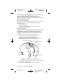
Theft Detectors and Screening Devices
Patients should be advised to use care when approaching security arches
or gates (such as those found in airports, libraries, and some department
stores) because these devices can turn on or turn off their neurostimulator.
If an airport security wand is used, they should ask the security personnel
to avoid placing the wand over the neurostimulator.
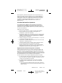
When approaching these devices, patients should do the following:
1. If security personnel are present, show them the neurostimulator
identification card and request a hand search.
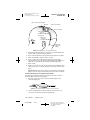
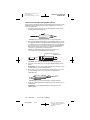
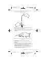
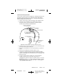
2. If patients must pass through the security device, they should
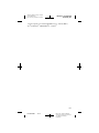
approach the center of the device and walk normally (Figure 24).
a. If two security gates are present, they should walk through the
middle, keeping as far away as possible from each gate.
b. If one gate is present, they should walk as far away as possible
from it.
Note: Some theft detectors may not be visible.
3. Proceed through the security device. Do not linger near the device.
34
English
MA16140A002
Technical Manual
Rev A
Refer to the “Technical Manual”
category in doc# A00002 for Neuro
Core European Printing
Instructions.
3387-89_CH.fm 3/22/06 1:25 pm
UC200xxxxxx EN
4.3 x 8 inches (108 mm x 203 mm)
Double Security
Gate
Medtronic Confidential
medvitld_R03
Single Security Gate
(Stay as far away as
possible from gate)
Figure 24. Approaching security gates
4. If patients suspect that their neurostimulator was turned off, they
should make sure someone is able to turn on the system again. (This
person could be the patient, if their medical condition allows it. It
could also be a family member or clinician who has been taught how
to use the system.)
Technical Manual
MA16140A002
Rev A
English
35
Refer to the “Technical Manual”
category in doc# A00002 for Neuro
Core European Printing
Instructions.
Medtronic Confidential
medvitld_R03
3387-89_CH.fm 3/22/06 1:25 pm
UC200xxxxxx EN
4.3 x 8 inches (108 mm x 203 mm)
Specifications
Lead length
10–50 cm
Lead shape
Straight
Lead body diameter
1.27 mm
Connector
In-Line
Number of electrodes
4
Electrode shape
Cylindrical
Electrode spacing (edge to edge)
0.5 mm (3389)
1.5 mm (3387)
Number of conductor wires
4
Material:
Conductor wires
Proximal connector
Stimulating electrodes
Platinum/Iridium
Nickel Alloy (MP35N)
Platinum/Iridium
Insulation:
Conductor wires
Fluoropolymer
Jacket tubing
Conductor resistance
Stylet materials
80A Urethane
<100 Ω
Tungsten
Materials in contact with human tissuea
Platinum/Iridium
80A Urethane
Nylon
Silicone
a
Includes implanted accessories
Notes:
■
The electrical resistance of leads is proportional to their length. Very
long leads have an increased resistance, which may limit pulse
amplitude at the electrodes.
■
All dimensions are approximate
General Warning
Medtronic lead kits consist of leads and tools to connect the lead to
implantable extensions. DBS leads are implanted in the extremely hostile
environment of the human body. Leads may fail to function for a variety of
causes, including, but not limited to, medical complications, body rejection
phenomena, fibrotic tissue, breakage, or breach of their insulation
covering. In addition, leads and tools may be easily damaged by improper
handling or use.
36
English
MA16140A002
Technical Manual
Rev A
Refer to the “Technical Manual”
category in doc# A00002 for Neuro
Core European Printing
Instructions.
3387-89OPN.fm 3/22/06 1:25 pm
UC200xxxxxx FR
4,3 x 8 inches (108 mm x 203 mm)
Medtronic Confidentiel
medvitld_R03
1
2
3
4
Instructions d'ouverture de l'emballage stérile
37
MA16140A002
Rév A
Refer to the “Technical Manual”
category in doc# A00002 for Neuro
Core European Printing
Instructions.
3387-89OPN.fm 3/22/06 1:25 pm
UC200xxxxxx FR
4,3 x 8 inches (108 mm x 203 mm)
Medtronic Confidentiel
medvitld_R03
38
MA16140A002
Rév A
Refer to the “Technical Manual”
category in doc# A00002 for Neuro
Core European Printing
Instructions.
Medtronic Confidentiel
medvitld_R03
3387-89_SYM.fm 3/22/06 1:25 pm
UC200xxxxxx FR
4,3 x 8 inches (108 mm x 203 mm)
Explication des symboles figurant sur l'emballage
Se reporter à l'emballage pour connaître les symboles qui s'appliquent à
ce produit
Conformité Européenne. Ce symbole signifie que
l’appareil est entièrement conforme à la Directive
Européenne 90/385/CEE.
Attention : Consulter les documents joints
À utiliser jusqu'au
STERILE EO
Stérilisation : Gaz d'oxyde d'éthylène
Ne pas réutiliser
+XX °C
+XXX °F
-XX °C
-XX °F
LOT
L E A D
Température de stockage
Numéro de lot
Longueur de l'électrode
Date de fabrication
Ouvrir ici
39
MA16140A002
Rév A
Refer to the “Technical Manual”
category in doc# A00002 for Neuro
Core European Printing
Instructions.
MA16140A002
2 3
Rév A
1
2
12,1 mm
10,6 mm
1,5 mm
3
Ø 1,27 mm (8x)
1,5 mm (3x)
Extrémité distale
Ø 1,27 mm (8x)
3
Ø 1,27 mm
Ø 1,27 mm
Remarque : Les Modèles 3387 et 3389 sont disponibles en longueur de 28 cm.
0
1,5 mm
(4x)
Modèle 3387
9,0 mm
7,5 mm
1,5 mm
0 1
1,5 mm 0,5 mm
(4x)
(3x)
Modèle 3389
0
0
1
2
3
2
3
40 mm
16,6 mm
2 mm (4X)
1
Extrémité proximale
16,6 mm
40 mm
2 mm (4X)
3387-89_SYM.fm 3/22/06 1:25 pm
UC200xxxxxx FR
4,3 x 8 inches (108 mm x 203 mm)
Medtronic Confidentiel
medvitld_R03
Figure A. Électrodes DBS Modèles 3389 et 3387.
Toutes les dimensions sont approximatives.
40
Refer to the “Technical Manual”
category in doc# A00002 for Neuro
Core European Printing
Instructions.
3387-89_SYM.fm 3/22/06 1:25 pm
UC200xxxxxx FR
4,3 x 8 inches (108 mm x 203 mm)
Medtronic Confidentiel
medvitld_R03
Les dénominations suivantes sont des marques commerciales de
Medtronic, Inc. : Activa®, DBS™, Itrel® II, Medtronic®, PERCUPASS® II et
Soletra®.
41
MA16140A002
Rév A
Refer to the “Technical Manual”
category in doc# A00002 for Neuro
Core European Printing
Instructions.
3387-89_SYM.fm 3/22/06 1:25 pm
UC200xxxxxx FR
4,3 x 8 inches (108 mm x 203 mm)
Medtronic Confidentiel
medvitld_R03
42
MA16140A002
Rév A
Refer to the “Technical Manual”
category in doc# A00002 for Neuro
Core European Printing
Instructions.
Medtronic Confidentiel
medvitld_R03
3387-89TOC.fm 3/22/06 1:25 pm
UC200xxxxxx FR
4,3 x 8 inches (108 mm x 203 mm)
Table des matières
Introduction 45
Contenu de l’emballage stérile 45
Indications 45
Contre-indications 46
Avertissements 46
Précautions 49
Interférences électromagnétiques (IEM)
Effets secondaires 53
Élimination du dispositif 54
Restérilisation
52
54
Procédures conseillées 55
Procédure d'implantation de l'électrode 55
Stimulation test peropératoire 57
Retrait du mandrin et stabilisation de l'électrode 62
Protection du connecteur 65
Stimulation test approfondie 66
Programmation des paramètres de stimulation 69
Instructions du médecin au patient 71
Détecteurs de vol et appareils de sécurité
Caractéristiques techniques
Avertissement général
71
73
73
Manuel technique
MA16140A002
Rév A
Français
43
Refer to the “Technical Manual”
category in doc# A00002 for Neuro
Core European Printing
Instructions.
3387-89TOC.fm 3/22/06 1:25 pm
UC200xxxxxx FR
4,3 x 8 inches (108 mm x 203 mm)
44
Français
MA16140A002
Medtronic Confidentiel
medvitld_R03
Manuel technique
Rév A
Refer to the “Technical Manual”
category in doc# A00002 for Neuro
Core European Printing
Instructions.
Medtronic Confidentiel
medvitld_R03
3387-89_CH.fm 3/22/06 1:25 pm
UC200xxxxxx FR
4,3 x 8 inches (108 mm x 203 mm)
Introduction
Le système Activa de Medtronic est un système quadripolaire implantable,
multiprogrammable qui délivre une stimulation électrique à des zones
spécifiques du cerveau.
Les électrodes DBS Modèles 3387 et 3389 de Medtronic sont conçues
pour la stimulation électrique de zones spécifiques du cerveau (stimulation
cérébrale profonde). L'électrode DBS Modèle 3387 présente un espace
important (1,5 mm) entre chacun des quatre plots de l'extrémité distale.
L'électrode DBS Modèle 3389 présente un espace étroit (0,5 mm) entre
chacun des quatre plots de l'extrémité distale.
Contenu de l’emballage stérile
Le kit d'électrode DBS de Medtronic se compose des éléments suivants :
Électrode :
■
Une électrode Modèle 3387 ou 3389
Accessoires :
■
Mandrin droit (inséré dans l'électrode)
■
Clef hexagonale ordinaire
■
Mandrin court
■
Câbles du stimulateur test
– Câble du stimulateur test à pinces crocodiles
– Câble avec connecteur autobloquant du stimulateur test
■
Mécanisme d’arrêt de profondeur
■
Anneau de fixation et capuchon
■
Capuchon de protection du connecteur
■
Tunnellisateur PERCUPASS II et embout de tunnellisation en acier
inoxydable
■
Tubes en fluoropolymère (tubes-guides)
■
Capuchon de l'électrode
Remarque : Tous les matériaux des électrodes Modèles 3387 ou 3389 de
Medtronic ont été sélectionnés pour leur biocompatibilité après analyses
en laboratoire, essais sur animal et essais cliniques. Tous les accessoires
contenus dans le kit d'électrode DBS Modèle 3387 ou 3389 de Medtronic
sont à USAGE UNIQUE EXCLUSIVEMENT.
Indications
Le système DBS est indiqué pour le traitement des patients souffrant de
tremblements invalidants ou présentant des symptômes de la maladie de
Parkinson. Des études récentes ont montré que la stimulation cérébrale
profonde est efficace pour contrôler les tremblements essentiels et les
symptômes de la maladie de Parkinson rebelles au traitement médical. En
outre, la stimulation cérébrale profonde est efficace pour contrôler les
dyskinésies et les fluctuations associées au traitement médical de la
maladie de Parkinson.
Manuel technique
MA16140A002
Rév A
Français
45
Refer to the “Technical Manual”
category in doc# A00002 for Neuro
Core European Printing
Instructions.
3387-89_CH.fm 3/22/06 1:25 pm
UC200xxxxxx FR
4,3 x 8 inches (108 mm x 203 mm)
Medtronic Confidentiel
medvitld_R03
Contre-indications
L’implantation d’un système de stimulation cérébrale Activa est contreindiquée chez les :
■
Patients exposés à une diathermie. Ne pas utiliser la diathermie à
ondes courtes, la diathermie micro-ondes ou la diathermie
thérapeutique à ultrasons (procédures regroupées sous le terme
“diathermie”) chez des patients porteurs d'un système de
neurostimulation implantable. L'énergie générée par la diathermie
est susceptible d'être transmise par le système implanté et de
provoquer des lésions tissulaires au niveau du site d'implantation des
électrodes, entraînant des lésions graves ou mortelles.
La diathermie est également contre-indiquée parce qu'elle peut
endommager les composants du système de neurostimulation, avec
pour conséquence la perte d’efficacité du traitement, nécessitant un
remplacement du système. Des lésions tissulaires et un
endommagement du système peuvent survenir lors d’un traitement
par diathermie même si le système de neurostimulation est à l'arrêt.
Recommander aux patients d'informer l'ensemble du personnel
médical qu'ils ne doivent pas être traités par diathermie.
■
Patients qui doivent être exposés à une IRM avec bobine RF corps
entier, une bobine de réception de tête ou une bobine de
transmission de tête qui déborde sur la région thoracique. Ces types
d'IRM peuvent provoquer des lésions tissulaires dues à
l'échauffement des composants, notamment des plots des
électrodes, pouvant entraîner un coma, une paralysie, voire le décès
du patient. Consulter le manuel des directives IRM fourni avec ce
produit pour obtenir des informations et des instructions de sécurité
détaillées.
■
Patients pour qui la stimulation test a échoué.
■
Patients incapables d’utiliser correctement le système.
Avertissements
Anti-coagulants – L'implantation d'électrodes chez les patients
présentant un risque accru d'hémorragie intracrânienne doit faire l'objet de
précautions extrêmes. Le médecin doit tenir compte des facteurs sousjacents, par exemple les antécédents de lésions neurologiques ou les
médicaments prescrits (anticoagulants) susceptibles de prédisposer le
patient à un risque hémorragique.
Stimulation excessive – Les amplitudes et durées d'impulsion élevées
entraînent un risque de dommage tissulaire. Les paramètres de stimulation
permettant la suppression des symptômes sont généralement compris
entre 1 et 4 V (amplitude), 60 et 180 µsec (durée d'impulsion) et 130 à
185 Hz (fréquence). Des valeurs supérieures à 7 V et à 250 µsec ont
rarement été appliquées en pratique clinique. Des amplitudes et durées
d’impulsion élevées peuvent indiquer un problème du système ou un
positionnement médiocre des électrodes.
Les valeurs de paramètre excédant les plages recommandées doivent être
programmées uniquement selon les directives relatives à la densité de
charge décrites à la section “Programmation des paramètres de
stimulation” à la page 69.
46
Français
MA16140A002
Manuel technique
Rév A
Refer to the “Technical Manual”
category in doc# A00002 for Neuro
Core European Printing
Instructions.
3387-89_CH.fm 3/22/06 1:25 pm
UC200xxxxxx FR
4,3 x 8 inches (108 mm x 203 mm)
Medtronic Confidentiel
medvitld_R03
Déséquilibre de charge (neurostimulateurs Soletra Modèle 7426 et
Itrel II Modèle 7424) – Certains paramètres de stimulation du
neurostimulateur peuvent provoquer un déséquilibre de charge, dans
lequel le circuit ne récupère pas la charge négative totale produite par les
activations du dispositif. Si le déséquilibre de charge (courant continu net)
dépasse un courant moyen de 1,5 µamp, les tissus risquent d'être
endommagés.
Pour éviter cette situation, ne pas programmer le neurostimulateur Soletra
Modèle 7426 ou le neurostimulateur Itrel II Modèle 7424 en mode cyclique
ou en mode de stimulation par rampe pour une stimulation cérébrale
profonde. Le programmateur affiche un avertissement en cas de choix du
mode cyclique ou du mode de stimulation par rampe. Pour des
informations complémentaires, contacter Medtronic.
En cas de programmation du neurostimulateur avec la fonction Démarrage/
arrêt progressif, consulter le Tableau 1 pour des conseils sur la
programmation de la stimulation thérapeutique. Vérifier la valeur de
l'amplitude et de la durée d'impulsion. Le neurostimulateur ne doit pas
dépasser le nombre d'activations indiqué pour les paramètres
sélectionnés. Une activation se produit lors d'une mise en marche ou arrêt
du neurostimulateur par l'aimant ou par le programmateur.
Il faudrait plus de 50.000 activations en 24 heures pour générer un
déséquilibre de charge avec les paramètres types visant la suppression
des symptômes (fréquence = 185 Hz, amplitude = 3 V et durée
d'impulsion = 90 µsec). Généralement, le patient ALLUME le
neurostimulateur le matin et l'ÉTEINT pour la nuit, ce qui correspond à une
activation du dispositif.
Manuel technique
MA16140A002
Rév A
Français
47
Refer to the “Technical Manual”
category in doc# A00002 for Neuro
Core European Printing
Instructions.
MA16140A002
Rév A
a
6,700
10,1-10,5
3,100
3,500
4,000
4,600
6,200
6,600
7,800
8,900
13,000
16,000
30,000
50,000
50,000
73,000
135,000
1,500
1,800
2,100
2,500
3,200
3,500
5,000
5,500
8,300
12,000
19,000
32,000
50,000
73,000
135,000
260
330
430
570
840
840
1,200
1,600
2,500
5,000
5,600
7,600
17,000
32,000
135,000
Activation de
l'appareil
sur 24 heures
Durée d'impulsion
programmée
150-210 µs
110
130
160
200
240
240
380
580
1,100
2,200
2,200
3,200
6,500
23,000
135,000
Activation de
l'appareil
sur 24 heures
Durée d'impulsion
programmée
270-330 µs
Une activation correspond à une mise en marche et arrêt du neurostimulateur, effectuée à l'aide de l'aimant patient ou du programmateur.
7,600
9,7-10,0
14,000
6,1-6,5
7,900
16,000
5,2-6,0
9,1-9,5
22,000
4,1-5,0
8,800
29,000
3,7-4,0
8,2-9,0
54,000
3,1-3,6
10,000
54,000
2,1-3,0
7,4-8,0
81,000
1,1-2,0
12,000
101,000
0,2-1,0
6,7-7,2
135,000
0,0-0,1
Activation de
l'appareil
sur 24 heures
Durée d'impulsion
programmée
120 µs
90
100
110
120
140
140
200
300
600
1,000
1,000
1,800
4,200
13,000
81,000
Activation de
l'appareil
sur 24 heures
Durée d'impulsion
programmée
400-450 µs
Français
Activation de
l'appareil
sur 24 heures
Durée d'impulsion
programmée
90 µs
Amplitude
programmée
(volts)
48
Activation de
l'appareil
sur 24 heures
Durée d'impulsion
programmée
60 µs
Tableau 1. Nombre maximum d'activations autorisées de l'appareila sur 24 heures. (Pour toutes les fréquences et combinaisons de plots programmables, la fonction
Démarrage progressif est activée)
3387-89_CH.fm 3/22/06 1:25 pm
UC200xxxxxx FR
4,3 x 8 inches (108 mm x 203 mm)
Medtronic Confidentiel
medvitld_R03
Manuel technique
Refer to the “Technical Manual”
category in doc# A00002 for Neuro
Core European Printing
Instructions.
3387-89_CH.fm 3/22/06 1:25 pm
UC200xxxxxx FR
4,3 x 8 inches (108 mm x 203 mm)
Medtronic Confidentiel
medvitld_R03
Imagerie par résonance magnétique – Avant de réaliser une IRM sur un
patient porteur d'un composant Activa, il est impératif de lire attentivement
toutes les consignes relatives à l'IRM présentées dans ce manuel. L'IRM
devra être effectuée avec les paramètres indiqués ici. Tout manquement
par rapport aux avertissements et aux consignes concernant les IRM
pourrait entraîner des lésions graves permanentes (coma, paralysie), voire
le décès du patient. Consulter le manuel des directives IRM fourni avec ce
produit pour obtenir des informations et des instructions de sécurité
détaillées.
Activités des patients – Des interférences électromagnétiques élevées
(IEM) à proximité du patient peuvent allumer ou éteindre le
neurostimulateur. Le système peut également s'arrêter de fonctionner de
manière inattendue par suite de l'usure normale de la pile ou d'autres
causes. Pour ces raisons, il convient d’informer le patient sur les activités
à risque susceptibles de présenter un danger si les troubles de motricité
réapparaissent accidentellement.
Utilisation en pédiatrie – La sécurité et l'efficacité de ce système n'ont
pas été établies pour une utilisation en pédiatrie.
Positionnement du connecteur électrode-extension – La sécurité et
l'efficacité du positionnement du connecteur électrode-extension au niveau
du cou n'ont pas été établies ; un nombre plus élevé de rupture de
l'électrode a été signalé dans ces cas-là.
Grossesse – La sécurité de ce système lors d'une utilisation durant la
grossesse ou l'accouchement n'a pas été établie.
Détecteurs de vol et appareils de sécurité – Les détecteurs de vol
équipant les magasins, les bibliothèques, etc. ainsi que les appareils de
sécurité, notamment des aéroports, peuvent allumer ou éteindre la source
d'alimentation d'un système de neurostimulation. Il est également possible
que des patients sensibles, ou avec des seuils de stimulation faibles,
ressentent une augmentation passagère de la stimulation. Dans d’autres
indications, certains patients décrivent l’augmentation des niveaux de
stimulation lors du franchissement de tels appareils, comme inconfortable
(secousses ou chocs). Consulter la section “Instructions du médecin au
patient” à la page 71 pour de plus amples informations.
Précautions
Stockage et stérilisation
Restérilisation – Consulter la section “Restérilisation” à la page 54 pour
de plus amples informations.
Température de stockage – L'électrode DBS doit être stockée à une
température comprise entre –34 °C et 57 °C. Toute température hors de
cette plage risque d'endommager les composants.
Système et thérapie
Défaillance des composants – Le médecin doit être conscient que tout
système de neurostimulation peut cesser de fonctionner de manière
intempestive. Un système peut tomber en panne à tout moment suite à des
défaillances imprévisibles de composants du système ou de la pile (avant
son épuisement normal). Ces événements, notamment les courts-circuits,
les circuits ouverts et les ruptures d'isolant, sont imprévisibles.
Manuel technique
MA16140A002
Rév A
Français
49
Refer to the “Technical Manual”
category in doc# A00002 for Neuro
Core European Printing
Instructions.
3387-89_CH.fm 3/22/06 1:25 pm
UC200xxxxxx FR
4,3 x 8 inches (108 mm x 203 mm)
Medtronic Confidentiel
medvitld_R03
Composants – L'utilisation de composants d'une autre marque que
Medtronic avec ce système risque d'endommager les composants de
Medtronic, d'interrompre la stimulation ou de provoquer des lésions chez le
patient.
Programmation accidentelle – La coexistence de plusieurs
neurostimulateurs chez un patient augmente le risque de modifications
intempestives de la programmation d'un des dispositifs. Lorsque deux
neurostimulateurs sont implantés, ils doivent être distants d'au moins
20 cm afin de minimiser les interférences. Vérifier les paramètres
programmés finaux en examinant les deux dispositifs à la fin de chaque
session de programmation.
Aimant patient – L'aimant permettant au patient d'activer et de désactiver
le neurostimulateur est susceptible d'endommager les postes de
télévision, les disquettes d'ordinateur, les cartes de crédit et autres
éléments sensibles à des champs magnétiques puissants.
Suivi du patient – Pour obtenir un bénéfice maximum avec le système de
neurostimulation, un suivi postchirurgical à long terme des patients est
recommandé.
Programmation des différents modèles de neurostimulateurs – Le
programmateur médecin Modèle 7432 doit être éteint et rallumé avant la
programmation d'un autre modèle de neurostimulateur (par exemple, pour
programmer un neurostimulateur Soletra Modèle 7426 immédiatement
après avoir programmé un neurostimulateur Itrel II Modèle 7424). Si le
programmateur n’est pas éteint puis rallumé, l’appareil affichera sur l’écran
“PAS DE TELEMETRIE, POSITIONNER LA TETE ET ESSAYER A
NOUVEAU” et le logiciel n’autorisera pas la programmation d’un autre
neurostimulateur.
Implantation et explantation
Détérioration du boîtier – Si le boîtier du neurostimulateur est cassé ou
perforé en raison de contraintes externes, l'exposition aux composants
chimiques de la pile peut provoquer des brûlures graves.
Mise au rebut des composants – Consignes à respecter lors de
l'explantation d'un composant du système :
■
Ne jamais incinérer un neurostimulateur ; la température élevée
risquerait de faire exploser le dispositif.
■
Renvoyer tous les composants explantés à Medtronic pour analyse
et élimination.
Connexions – Enlever toute trace de liquides corporels sur les contacts
des électrodes ou du connecteur avant d'effectuer les raccordements. La
contamination des connexions risque d'affecter la neurostimulation.
Identification gravée – Placer le neurostimulateur, côté identification vers
l'extérieur, à l'opposé du plan musculaire. Ceci permet de limiter le risque
de stimulation musculaire pouvant être assimilée à une secousse ou une
sensation de brûlure.
Manipulation des composants – Manipuler les composants
implantables avec le plus grand soin. Ces composants peuvent être
endommagés suite à une contrainte excessive ou au contact avec des
instruments tranchants.
50
Français
MA16140A002
Manuel technique
Rév A
Refer to the “Technical Manual”
category in doc# A00002 for Neuro
Core European Printing
Instructions.
3387-89_CH.fm 3/22/06 1:25 pm
UC200xxxxxx FR
4,3 x 8 inches (108 mm x 203 mm)
Medtronic Confidentiel
medvitld_R03
■
Veiller à ne pas plier, tordre ou étirer le corps de l'électrode, que le
mandrin soit installé ou non. Ne pas plier ni tordre le mandrin de
tungstène.
■
Ne pas effectuer de suture directement sur le corps de l'électrode ou
l'extension. Utiliser l'anneau de fixation et le capuchon fournis par
Medtronic pour fixer l'électrode.
■
S'il s'avère nécessaire de manipuler l'électrode avec une pince,
utiliser exclusivement une pince à baïonnette munie d'embouts en
caoutchouc.
■
Être extrêmement prudent en utilisant des instruments tranchants
autour de l'électrode afin d'éviter d'entailler ou d'endommager
l'isolation de l'électrode.
Éléments à prendre en compte avant l'implantation – Ne pas
implanter un composant dans les cas suivants :
■
L’emballage de stockage est percé ou endommagé, le composant
semble endommagé ; ou
■
La date de péremption est dépassée, car cela peut avoir un impact
négatif sur la stérilité de l’emballage de stockage.
Environnement médical
La plupart des procédures diagnostiques de routine, tels que la radioscopie
et la radiographie, ne devraient pas affecter le fonctionnement du système.
Il convient cependant d'observer les précautions suivantes.
Effet sur les dispositifs médicaux – Le système de neurostimulation
peut affecter le fonctionnement d'autres dispositifs implantés, comme des
stimulateurs ou des défibrillateurs. Parmi les effets potentiels, citons les
problèmes de détection et des réponses inadéquates de ces dispositifs. Si
le patient requiert une thérapie concomitante par stimulateur et/ou
défibrillateur implantable, procéder à une programmation rigoureuse de
chaque système afin d'optimiser les bénéfices de chaque dispositif.
Bistouri électrique – Les bistouris électriques peuvent interrompre
temporairement la neurostimulation et/ou modifier la programmation du
neurostimulateur. Si l'utilisation d'un bistouri électrique s'avère
indispensable, le trajet du courant (plaque de masse) doit être maintenu le
plus loin possible du neurostimulateur et de l'électrode. Il est également
conseillé d’utiliser un cautère bipolaire.
Défibrillateurs externes – La sécurité de l'utilisation de décharges de
défibrillation administrées à un patient porteur d’un système de
neurostimulation n’a pas été établie. Une défibrillation externe peut
endommager un neurostimulateur.
Si la défibrillation externe est nécessaire et que les circonstances le
permettent, observer les précautions suivantes pour minimiser le courant
traversant le neurostimulateur et le système électrode-extension :
■
Placer les plaques de défibrillation le plus loin possible du
neurostimulateur.
■
Placer les plaques de défibrillation perpendiculairement au système
neurostimulateur/électrode implanté.
■
Utiliser le niveau d'énergie cliniquement adapté le plus faible (watts
secondes).
Manuel technique
MA16140A002
Rév A
Français
51
Refer to the “Technical Manual”
category in doc# A00002 for Neuro
Core European Printing
Instructions.
Medtronic Confidentiel
medvitld_R03
3387-89_CH.fm 3/22/06 1:25 pm
UC200xxxxxx FR
4,3 x 8 inches (108 mm x 203 mm)
■
Vérifier le bon fonctionnement du système de neurostimulation après
toute défibrillation externe.
Sources de radiations intenses – Des sources de radiation intenses,
comme le cobalt 60 ou le rayonnement gamma, ne doivent pas être
dirigées vers le neurostimulateur. Si un patient requiert une radiothérapie
à proximité du neurostimulateur, placer un écran de protection au-dessus
du dispositif pour éviter les dommages dus aux rayons.
Lithotripsie – L’utilisation d’appareils à forte concentration d’ultrasons,
comme les lithotripteurs, est déconseillée chez les patients porteurs d’un
système de neurostimulation. Bien que sans danger pour le patient,
l’exposition aux ultrasons à hautes intensités est susceptible
d’endommager les circuits du neurostimulateur. Si une lithotripsie est
indispensable, éviter de concentrer le faisceau au voisinage du
neurostimulateur.
Interférences électromagnétiques (IEM)
Les interférences électromagnétiques se manifestent par un champ
(électrique, magnétique, ou une combinaison des deux) généré par divers
appareils environnementaux ou médicaux. Ces appareils médicaux et
environnementaux (domestiques, professionnels et autres) peuvent
générer suffisamment d’interférences pour modifier les paramètres d’un
neurostimulateur, allumer et éteindre un neurostimulateur ou entraîner une
augmentation de la tension, donner un choc électrique ou secouer le
patient.
L’extension, l’électrode ou les deux peuvent également "véhiculer" les
interférences électromagnétiques et délivrer un excédent de tension
susceptible de provoquer une élévation de température au niveau du
cerveau. Voir les sections qui suivent pour les directives sur l'interaction
entre les interférences électromagnétiques et un système Activa implanté.
Techniques psychothérapeutiques – La sécurité des techniques
psychothérapeutiques faisant appel à un équipement qui génère des
interférences électromagnétiques (électrochocs, stimulation magnétique
transcrânienne, etc.) n'a pas été établie.
Environnement domestique ou professionnel
Appareils électriques domestiques – Les appareils électroménagers en
bon état de fonctionnement et correctement reliés à la terre, ne produisent
généralement pas suffisamment d'interférences électromagnétiques (IEM)
pour affecter le fonctionnement du neurostimulateur. Toutefois, les articles
comportant des aimants (par exemple, des haut-parleurs stéréo, des
réfrigérateurs, des congélateurs) peuvent allumer ou éteindre le
neurostimulateur.
Environnement professionnel – Le matériel électrique industriel (postes
de soudure à l'arc ou par points, fours à induction), le matériel de
communication (émetteurs micro-ondes, amplificateurs de puissance
linéaires, émetteurs amateurs puissants) et les lignes électriques à haute
tension peuvent générer suffisamment d'interférences électromagnétiques
(IEM) pour affecter le fonctionnement du neurostimulateur si le patient est
trop près.
52
Français
MA16140A002
Manuel technique
Rév A
Refer to the “Technical Manual”
category in doc# A00002 for Neuro
Core European Printing
Instructions.
Medtronic Confidentiel
medvitld_R03
3387-89_CH.fm 3/22/06 1:25 pm
UC200xxxxxx FR
4,3 x 8 inches (108 mm x 203 mm)
Activités des patients et précautions relatives à l'environnement –
Les patients doivent être prudents vis-à-vis des appareils qui génèrent un
champ électrique ou magnétique puissant. Le voisinage immédiat
d’interférences électromagnétiques (IEM) intenses peut allumer ou
éteindre le neurostimulateur. Le système peut aussi cesser de fonctionner
par suite de l’usure normale de la pile ou d’autres causes. Pour ces raisons,
il convient d'informer le patient sur toutes les activités susceptibles de
présenter un danger si les symptômes réapparaissent accidentellement.
Pour plus d’informations sur les appareils qui génèrent des interférences
électromagnétiques, contacter le représentant local de Medtronic.
Aimant patient – L'aimant permettant au patient d'activer et de désactiver
le neurostimulateur est susceptible d'endommager les postes de
télévision, les disquettes et les écrans d'ordinateur, les cartes de crédit et
autres éléments sensibles à des champs magnétiques puissants.
Sources de fréquences radio – Les téléphones cellulaires numériques
et analogiques, les radios AM/FM, les téléphones sans fil et les téléphones
traditionnels peuvent contenir des aimants. Pour éviter les arrêts ou
déclenchements intempestifs de la stimulation, ces appareils ne doivent
jamais être à moins de 10 cm du neurostimulateur implanté.
Aimants thérapeutiques – Les aimants thérapeutiques (notamment des
bracelets, corsets lombaires, semelles et protège-matelas) peuvent
provoquer des arrêts ou déclenchements intempestifs du neurostimulateur.
Les patients doivent donc être informés qu’ils ne doivent pas les utiliser.
Effets secondaires
Les effets secondaires potentiels de la stimulation cérébrale profonde
sont :
■
Réaction allergique ou réponse du système immunitaire aux
matériaux implantés
■
Infection
■
Hémorragie intracrânienne immédiate ou tardive susceptible
d’entraîner une faiblesse musculaire temporaire ou permanente, une
paralysie, une aphasie ou le décès du patient
■
Érosion ou migration de l'électrode, de l’extension et du
neurostimulateur
■
Rupture de l’électrode et de l’extension
■
Perte de l’effet thérapeutique
■
Diminution des facultés mentales : déficits de l’attention ou des
connaissances, troubles de la mémoire, confusion ou troubles
psychiatriques
■
Troubles de motricité : parésie, faiblesse, manque de coordination,
spasmes musculaires, troubles de la marche, tremblements,
dystonie ou chorée
■
Neurostimulation en permanence douloureuse ou désagréable
■
Crises comitiales
■
Modifications sensorielles
■
Sérome ou hématome au niveau du site d'implantation du
neurostimulateur
■
Troubles de l’élocution : dysphasie ou dysarthie
Manuel technique
MA16140A002
Rév A
Français
53
Refer to the “Technical Manual”
category in doc# A00002 for Neuro
Core European Printing
Instructions.
3387-89_CH.fm 3/22/06 1:25 pm
UC200xxxxxx FR
4,3 x 8 inches (108 mm x 203 mm)
Medtronic Confidentiel
medvitld_R03
■
Sensations indésirables, par exemple paresthésie potentiellement
temporaire ou permanente
■
Troubles visuels, par exemple diplopie, troubles de motricité
oculaires ou autres troubles du champ visuel
Remarque : La modification de la position de l'électrode pendant
l'intervention chirurgicale ou la modification des paramètres de stimulation
pendant l'intervention ou la stimulation test permettent de limiter ou de
supprimer bon nombre des effets indésirables.
Élimination du dispositif
Éliminer le dispositif conformément à la réglementation environnementale
locale.
Restérilisation
L'électrode et les accessoires du kit d'électrode DBS ont été stérilisés à
l'oxyde d'éthylène avant expédition. Vérifier l'intégrité de l'emballage stérile
avant utilisation, afin de détecter tout dommage éventuel. En cas de doute
sur la stérilité des composants pour une raison quelconque, ceux-ci
peuvent être restérilisés en milieu hospitalier.
Remarque : Si l’ouverture d'une fermeture stérile de l'emballage fait
craindre une contamination, les électrodes et les accessoires peuvent être
renvoyés à Medtronic pour remplacement ou restérilisés à l’hôpital.
Medtronic n'accepte pas les électrodes ou accessoires renvoyés pour
restérilisation.
En raison de la diversité des stérilisateurs hospitaliers, il n'est pas possible
de fournir des instructions précises de stérilisation et d'aération dans ce
manuel. Si des informations plus détaillées concernant les procédures de
stérilisation sont nécessaires, contacter le fabricant de l'appareil de
stérilisation. Utiliser des indicateurs biologiques ou toute autre méthode
acceptable pour confirmer l'efficacité du stérilisateur de l'hôpital.
Medtronic ne peut être tenu responsable de la restérilisation de tout
composant en milieu hospitalier. Si l'hôpital décide toutefois de procéder à
la restérilisation, recourir à des méthodes de stérilisation habituelles.
Attention :
■
Ne pas restériliser ni utiliser les électrodes ou les accessoires après
exposition aux liquides ou tissus corporels.
■
Ne pas recourir à des rayonnements ionisants pour restériliser un
composant. Ne pas autoclaver l'électrode, l'extension percutanée, le
mandrin, l'anneau de fixation/le capuchon, le capuchon de protection
du connecteur ou le capuchon de l'électrode.
Compte tenu de ce qui précède, les suggestions suivants doivent aussi
être considérées :
Le Tableau 2 récapitule les options et restrictions de restérilisation
applicables. Des informations complémentaires sont données à la suite du
tableau.
54
Français
MA16140A002
Manuel technique
Rév A
Refer to the “Technical Manual”
category in doc# A00002 for Neuro
Core European Printing
Instructions.
Medtronic Confidentiel
medvitld_R03
3387-89_CH.fm 3/22/06 1:25 pm
UC200xxxxxx FR
4,3 x 8 inches (108 mm x 203 mm)
Tableau 2. Options et restrictions de restérilisation
Méthodes de stérilisationa
Composant
Oxyde d'éthylène
Autoclave
55 oC maximum 121 oC, 103 kPa,
30 minutes
Autoclave flash
132 oC,
186 kPa,
5 minutes
Électrode
OUI
NON
NON
Extension percutanée
OUI
NON
NON
Mandrin
OUI
NON
NON
Câble du stimulateur test
OUI
OUIb
OUIc
Anneau de fixation/
capuchon, capuchon de
protection du connecteur,
capuchon de l'électrode
OUI
NON
NON
Autres accessoires
OUI
OUI
OUI
a
b
c
Medtronic ne peut être tenu responsable de la restérilisation de tout composant en
milieu hospitalier.
60 minutes
30 minutes
La restérilisation à l’oxyde d’éthylène est une méthode acceptable si les
électrodes et les accessoires sont réemballés dans un emballage
perméable à l’oxyde d’éthylène. La température ne doit pas dépasser
55 °C durant le processus. Respecter une durée d'aération maximum
avant d’implanter l’électrode et d’utiliser les accessoires.
L'autoclave à la vapeur peut également tenir lieu de méthode de
stérilisation pour les composants comportant le marquage OUI pour
l'autoclave dans le Tableau 2. Un cycle standard de 30 minutes à 121 °C et
103 kPa est recommandé. Pour les composants dont la stérilisation “flash”
en autoclave est indiquée dans le tableau, un cycle standard de 5 minutes
à 132 °C et 186 kPa est recommandé. Pour le câble du stimulateur test,
respecter les durées les plus longues. Les méthodes interdites ne doivent
pas être appliquées aux composants concernés.
Procédures conseillées
L'implantation de l'électrode DBS fait appel à la stéréotaxie pour
l'implantation du système initial et le suivi rigoureux du patient en cours de
phase postopératoire. Medtronic reconnaît qu'il existe un multitude
d'approches à cet effet. La procédure ci-dessous est présentée au
médecin comme l'une des approches possibles.
Le site d'implantation par stéréotaxie de l'électrode DBS peut être localisé
à l'aide de la tomodensitométrie, de l'IRM ou de la ventriculographie. L'effet
de la stimulation au moyen d'une électrode de test peut être utilisé pour
identifier le site cible préalablement à l'implantation de l'électrode DBS.
Procédure d'implantation de l'électrode
Les étapes ci-dessous détaillent une procédure suggérée pour
l'implantation de l'électrode DBS.
Manuel technique
MA16140A002
Rév A
Français
55
Refer to the “Technical Manual”
category in doc# A00002 for Neuro
Core European Printing
Instructions.
3387-89_CH.fm 3/22/06 1:25 pm
UC200xxxxxx FR
4,3 x 8 inches (108 mm x 203 mm)
Medtronic Confidentiel
medvitld_R03
Attention : Le mandrin inséré dans l'électrode DBS Modèle 3387 ou 3389
correspond spécialement à cette électrode ; les mandrins ne sont pas
interchangeables entre les Modèles 3387 et 3389 ou entre chaque
électrode.
1. Après la mise en place du cadre stéréotaxique sur le patient, utiliser
des techniques d'imagerie standards pour déterminer les
coordonnées de la cible d'implantation de l'électrode.
2. À l'issue de l'imagerie, préparer le patient en vue de la stéréotaxie.
a. Pratiquer une incision cutanée, en regard de la zone d'abord
cranien.
b. Préparer une poche sous-galéale à l'aide d'une dissection douce
en vue du placement du fil d'électrode excédentaire et du
connecteur. Lors de la création de la poche, tenir compte de
l'emplacement du trou de trépan et de la latéralité de la thérapie.
c. Pratiquer un trou de trépan de 14 mm de diamètre à l'endroit
souhaité.
Remarque : Medtronic recommande d'utiliser un perforateur de
14 mm à bord droit pour la réalisation du trou de trépan.
Attention : Utiliser uniquement un capuchon et un anneau de
fixation fournis par Medtronic pour fixer l'électrode en place.
3. À l'aide des doigts et de pinces hémostatiques courbes, placer
l'anneau de fixation fermement contre l'os à l'intérieur du trou.
4. Positionner le tube-guide ou le micro-descendeur dans le cadre de
manière à ce que son extrémité distale soit à une distance comprise
entre 1,25 et 2,5 cm du crâne.
Remarque : Si une canule d'insertion et un mandrin sont utilisés, la
canule doit être placée à environ 10 mm du site cible de stimulation.
5. Déterminer le site cible au moyen d'une électrode de test.
a. Placer l'électrode de test à 10 mm au-dessus du site cible. La
faire avancer lentement et délicatement de 1 mm à la fois et tester
la stimulation. Le site adéquat est déterminé lorsque des effets
thérapeutiques maximum sont obtenus tout en ayant des effets
secondaires minimum.
b. Une fois le site cible déterminé, consigner l'emplacement par
écrit.
Remarque : Il sera éventuellement nécessaire d'essayer d'autres
trajectoires pour obtenir un positionnement optimal.
6. Retirer l'électrode de test. Déterminer la profondeur du site
d'implantation de l'électrode DBS.
7. Attacher le mécanisme d'arrêt de profondeur de l'électrode sur
l'électrode au point calculé à l'étape 6.
8. Faire avancer l'électrode en suivant la trajectoire aménagée par
l'électrode de test.
Attention : Une augmentation de la résistance ou une friction
pendant l'insertion de l'électrode peut indiquer que celle-ci dévie de
la trajectoire prévue. Dans ce cas, retirer l'électrode et recommencer
la procédure d'avancement jusqu'à ce qu'elle atteigne le site cible.
56
Français
MA16140A002
Manuel technique
Rév A
Refer to the “Technical Manual”
category in doc# A00002 for Neuro
Core European Printing
Instructions.
Medtronic Confidentiel
medvitld_R03
3387-89_CH.fm 3/22/06 1:25 pm
UC200xxxxxx FR
4,3 x 8 inches (108 mm x 203 mm)
Stimulation test peropératoire
Cette section décrit le test de stimulation peropératoire qui permet de
confirmer que la position de l'électrode convient à une suppression
optimale des symptômes. Pour ce test, les composants suivants sont
nécessaires :
■
Un stimulateur test Modèle 3625
■
Un câble du stimulateur test à pinces crocodiles ou avec connecteur
autobloquant
Les procédures décrites dans cette section fournissent des instructions
pour la stimulation test au moyen d'un câble du stimulateur test à pinces
crocodiles ou avec connecteur autobloquant et d'un stimulateur test
Modèle 3625.
Stimulation test avec le câble du stimulateur test à pinces crocodiles
Le câble du stimulateur test à pinces crocodiles est bipolaire. La polarité de
la pince crocodile noire correspond au réglage du commutateur de plot "0",
tandis que celle de la pince crocodile rouge correspond au réglage du
commutateur de plot "3". Les commutateurs de plot "1" et "2" sont
inactifs. Utiliser les pinces crocodiles pour sélectionner les plots de
l'électrode correspondant aux plots que vous souhaitez tester.
Attention : Les commutateurs du stimulateur test Modèle 3625
correspondant aux plots "0" et "3" doivent être réglés manuellement pour
établir un circuit. Les réglages doivent configurer un plot positif et l'autre
négatif. Si les commutateurs de plot "0" et "3" ne sont pas réglés suivant ce
schéma, aucune stimulation ne se produira.
1. Attacher les pinces crocodiles aux contacts de l'électrode qui
correspondent aux plots choisis (la Figure 1 illustre la connexion aux
contacts de l'électrode pour les plots 0 et 3).
Rouge : Raccordement au
plot 3
Connecteur du
mandrin
Extrémité proximale
3
2
1
0
Noir : Raccordement au
plot 0
Extrémité distale
Électrode
Figure 1. Branchement des pinces sur les contacts de l'électrode.
2. Vérifier que la commande externe d'amplitude A du stimulateur test
(Figure 2) est ÉTEINTE.
Avertissement : ÉTEINDRE systématiquement la commande
externe d'amplitude A avant de brancher ou de débrancher le câble
du stimulateur test ou avant de changer les pinces crocodiles sur les
contacts de l'électrode pour éviter une stimulation gênante pour le
patient.
Manuel technique
MA16140A002
Rév A
Français
57
Refer to the “Technical Manual”
category in doc# A00002 for Neuro
Core European Printing
Instructions.
Medtronic Confidentiel
medvitld_R03
3387-89_CH.fm 3/22/06 1:25 pm
UC200xxxxxx FR
4,3 x 8 inches (108 mm x 203 mm)
3. Introduire la fiche du câble du stimulateur test dans la prise du
stimulateur test (Figure 2). Respecter l'orientation de la fiche ; elle
ne s'insère que dans un seul sens.
Commande externe d'amplitude A
Commande externe de
fréquence R
Ouverture du
couvercle des
commandes internes
Fiche du câble
Ouverture du
couvercle du
compartiment
de la pile
Borne du
stimulateur test
Figure 2. Commandes externes du stimulateur test Modèle 3625.
Avertissement : ÉTEINDRE systématiquement la commande
externe d'amplitude A du stimulateur test avant de brancher ou de
débrancher le câble du stimulateur test ou avant de modifier la
connexion des pinces crocodiles ou les commandes internes pour
éviter une stimulation gênante pour le patient.
4. Retirer le couvercle des commandes internes (Figure 2) et régler les
commandes internes (Figure 3) comme suit :
a. Régler les polarités des plots (SÉLECTION DES PLOTS) comme
indiqué.
Polarité de la
pince rouge
Polarité de la
pince noire
SELECTION DES PLOTS
+
+
+
OFF
OFF
OFF
_
0
_
1
_
2
3
ARRÊT (OFF) - non utilisé.
b. Régler le commutateur FRÉQUENCE et DURÉE D'IMPULSION
sur B.
c. Régler la FRÉQUENCE externe sur 130 Hz ou une autre valeur
(la plage thérapeutique correspond à 130–185 Hz). Ne pas
dépasser 185 Hz.
d. Régler la DURÉE D'IMPULSION sur 60 µsec ou sur une autre
valeur.
e. Régler la LIMITE AMPL sur 10 V ou sur une autre valeur.
58
Français
MA16140A002
Manuel technique
Rév A
Refer to the “Technical Manual”
category in doc# A00002 for Neuro
Core European Printing
Instructions.
Medtronic Confidentiel
medvitld_R03
3387-89_CH.fm 3/22/06 1:25 pm
UC200xxxxxx FR
4,3 x 8 inches (108 mm x 203 mm)
Fréquence
Commutateur
de fréquence
et de durée
d’impulsion
Amplitude
Durée
d’impulsion
Limite
d'amplitude
(Limite Ampl)
Sélection des
plots
Figure 3. Sélection des commandes internes/externes.
5. Mettre la commande externe d'amplitude A sur MARCHE et
augmenter progressivement jusqu'à ce que le patient sente un effet
ou jusqu'à ce que la stimulation entraîne la suppression des
symptômes.
Remarque : La stimulation optimale est obtenue lorsqu'une
amélioration notable des troubles de motricité est enregistrée avec
effets secondaires minimes.
6. Pour inverser la polarité de sortie :
a. Mettre la commande d'amplitude externe A sur ARRÊT.
b. Régler les polarités des plots (SÉLECTION DES PLOTS) comme
indiqué.
Polarité de la
pince noire
Polarité de la
pince rouge
SELECTION DES PLOTS
+
+
+
OFF
OFF
OFF
_
0
_
1
_
2
3
ARRÊT (OFF) - non utilisé.
Remarque : La polarité de sortie peut être également inversée en
commutant les pinces crocodiles sur les plots.
c. Répéter l'étape 5.
Avertissement : ÉTEINDRE systématiquement la commande
externe d'amplitude A du stimulateur test avant de modifier les
commutateurs SÉLECTION DES PLOTS ou autres commandes
internes pour éviter une stimulation gênante pour le patient.
7. À l'issue du test de stimulation peropératoire, mettre la commande
d'amplitude externe A du stimulateur test sur ARRÊT.
Manuel technique
MA16140A002
Rév A
Français
59
Refer to the “Technical Manual”
category in doc# A00002 for Neuro
Core European Printing
Instructions.
3387-89_CH.fm 3/22/06 1:25 pm
UC200xxxxxx FR
4,3 x 8 inches (108 mm x 203 mm)
Medtronic Confidentiel
medvitld_R03
8. Débrancher les pinces crocodiles du câble du stimulateur test des
plots de l'électrode.
Stimulation test avec le câble du stimulateur test avec connecteur
autobloquant
Le câble du stimulateur test avec connecteur autobloquant est
quadripolaire. Lorsque ce câble est connecté au stimulateur test
Modèle 3625, les quatre commutateurs de plot sont actifs.
Attention : Fixer le câble avant de brancher le câble du stimulateur test
avec connecteur autobloquant au connecteur du mandrin de l'électrode
DBS. Sinon, le poids du connecteur autobloquant risquerait de déplacer
l'électrode.
1. Vérifier que la sortie du stimulateur test (amplitude) est sur arrêt.
2. Insérer et verrouiller le connecteur du mandrin de l'électrode dans le
connecteur autobloquant du câble du stimulateur test. (Se référer
aux figures 4 à 7).
Remarque : Le connecteur ne s'insère dans le connecteur
cylindrique autobloquant que dans un seul sens (Figure 4).
Figure 4. Positionnement du connecteur du mandrin et du connecteur cylindrique
autobloquant.
Remarque : Placer le connecteur du mandrin dans la rainure en
l'inclinant légèrement pour fixer l'extrémité du connecteur.
Figure 5. Glissement du connecteur du mandrin dans la rainure.
60
Français
MA16140A002
Manuel technique
Rév A
Refer to the “Technical Manual”
category in doc# A00002 for Neuro
Core European Printing
Instructions.
3387-89_CH.fm 3/22/06 1:25 pm
UC200xxxxxx FR
4,3 x 8 inches (108 mm x 203 mm)
Medtronic Confidentiel
medvitld_R03
Figure 6. Enfoncement du connecteur du mandrin dans la rainure.
Figure 7. Verrouillage du connecteur autobloquant.
3. Vérifier que la sortie du stimulateur test (amplitude) est ÉTEINTE,
puis insérer la fiche de l'extrémité du câble côté stimulateur test dans
la fiche de sortie du stimulateur test (Figure 8). Se référer au Manuel
de l'utilisateur du stimulateur test Modèle 3625 pour des instructions
détaillées sur l'utilisation.
Avertissement : ÉTEINDRE systématiquement la sortie du
stimulateur test (amplitude) avant de brancher ou de débrancher le
câble du stimulateur test pour éviter une stimulation gênante pour le
patient.
Remarque : La fiche du câble du stimulateur test ne s'insère que
dans un seul sens dans la fiche du stimulateur test.
Figure 8. Branchement du câble sur le stimulateur test.
4. Procéder à la stimulation test. Se reporter aux étapes 4 à 8 de la
section “Stimulation test avec le câble du stimulateur test à pinces
crocodiles” en commençant à la page 57 pour consulter les
recommandations liées aux paramètres de stimulation.
5. Une fois la stimulation test peropératoire terminée, mettre le
stimulateur test sur ARRÊT.
6. Déverrouiller le connecteur cylindrique autobloquant et retirer le
connecteur.
Manuel technique
MA16140A002
Rév A
Français
61
Refer to the “Technical Manual”
category in doc# A00002 for Neuro
Core European Printing
Instructions.
3387-89_CH.fm 3/22/06 1:25 pm
UC200xxxxxx FR
4,3 x 8 inches (108 mm x 203 mm)
Medtronic Confidentiel
medvitld_R03
a. Tenir fermement l'extrémité du connecteur autobloquant côté
stimulateur test dans la main gauche et tourner l'extrémité du
connecteur autobloquant côté électrode dans le sens inverse des
aiguilles d'une montre avec la main droite jusqu'à ce que les
rainures de chaque côté soient alignées (Figure 9).
Figure 9. Déverrouillage du connecteur autobloquant.
b. Déloger doucement le connecteur côté électrode jusqu'à ce qu'il
puisse sortir du connecteur autobloquant.
Lorsque le mode et la configuration de stimulation optimum sont
déterminés, et les troubles de motricité supprimés, passer à la rubrique
“Retrait du mandrin et stabilisation de l'électrode” de la section suivante.
Retrait du mandrin et stabilisation de l'électrode
Lorsque le médecin a déterminé la position adéquate de l'électrode, celleci peut être fixée dans l'anneau de fixation.
Effectuer les étapes ci-dessous pour fixer l'électrode.
1. Retirer le mécanisme d'arrêt de profondeur de l'électrode.
Remarque : Si l'électrode a été insérée à l'aide d'une canule,
procéder comme suit :
a. Retirer délicatement la canule d'insertion jusqu'à ce que
l'électrode soit visible entre le trou de trépan et la canule.
b. Maintenir l'électrode à l'endroit où elle sort du crâne tout en
relâchant le connecteur du mandrin.
c. Retirer le mandrin de l'électrode.
d. Tout en maintenant l'électrode en place au site de sortie, retirer
l'électrode de son support.
e. Retirer la canule d'insertion.
f. Passer à l'étape 5.
2. Tenir l'électrode au point où elle sort du crâne tout en desserrant le
connecteur du mandrin (Figure 10).
3. Tout en maintenant l'électrode au niveau du crâne, retirer le mandrin
de l'électrode.
62
Français
MA16140A002
Manuel technique
Rév A
Refer to the “Technical Manual”
category in doc# A00002 for Neuro
Core European Printing
Instructions.
Medtronic Confidentiel
medvitld_R03
3387-89_CH.fm 3/22/06 1:25 pm
UC200xxxxxx FR
4,3 x 8 inches (108 mm x 203 mm)
Figure 10. Déconnexion du connecteur du mandrin de l'électrode.
4. Retirer le tube-guide ou micro-descendeur.
5. Insérer doucement l'électrode dans l'une des rainures prédécoupées
sur la partie interne de l'anneau de fixation (Figure 11).
Figure 11. Enfoncement avec précaution de l'électrode dans l'anneau de fixation.
6. Revérifier l'effet de la stimulation après la fixation de l'électrode.
7. Vérifier que la sortie du stimulateur test (amplitude) est sur ARRÊT.
8. Si le câble du stimulateur test à pinces crocodiles est utilisé, fixer
soigneusement les pinces crocodiles aux contacts de l'anneau du
connecteur souhaités à l’extrémité de l’électrode.
Avertissement : ÉTEINDRE systématiquement la sortie du
stimulateur test (amplitude) avant de modifier les connexions des
pinces crocodiles sur les anneaux du connecteur pour éviter une
stimulation gênante pour le patient.
9. Si le câble du stimulateur test avec connecteur autobloquant est
utilisé, procéder comme suit :
a. Fixer le mandrin court joint à l'extrémité proximale de l'électrode
(Figure 12).
Manuel technique
MA16140A002
Rév A
Français
63
Refer to the “Technical Manual”
category in doc# A00002 for Neuro
Core European Printing
Instructions.
Medtronic Confidentiel
medvitld_R03
3387-89_CH.fm 3/22/06 1:25 pm
UC200xxxxxx FR
4,3 x 8 inches (108 mm x 203 mm)
Figure 12. Fixation du mandrin court sur l'électrode.
b. Insérer le mandrin court à fond dans l'électrode (Figure 12a).
c. Fixer l'électrode dans le connecteur du mandrin (Figure 12b).
d. Insérer le connecteur du mandrin de l'électrode dans le
connecteur autobloquant cylindrique du câble du stimulateur test
et le verrouiller en place (se référer aux Figure 4 à Figure 7).
10. Allumer le stimulateur test et vérifier de nouveau les effets de la
stimulation.
Remarque : Si l'électrode s'est déplacée, il faudra éventuellement la
retirer et recommencer l'implantation avec une électrode neuve.
Avertissement : Si l'électrode doit être repositionnée, ne pas
réinsérer le mandrin dans l'électrode implantée. Utiliser une nouvelle
électrode.
11. Pour limiter le risque de déplacement de l'électrode, insérer le
capuchon dans l'anneau de fixation comme suit :
a. Aligner la marque du capuchon sur la fente de l'anneau de
fixation.
b. Tenir le capuchon incliné vers la fente de l'anneau, à l'endroit de
la fixation de l'électrode et enfoncer délicatement le capuchon
contre le bord de l'anneau de fixation et l'électrode (Figure 13a).
c. Appuyer légèrement sur le centre du capuchon et l'enfoncer dans
l'anneau jusqu'à ce qu'il soit en place (Figure 13b).
a
b
Figure 13. Enfoncement avec précaution du capuchon dans l'anneau de fixation.
12. Si une deuxième électrode est implantée, répéter la procédure.
13. Préparer le patient à l'implantation du neurostimulateur.
64
Français
MA16140A002
Manuel technique
Rév A
Refer to the “Technical Manual”
category in doc# A00002 for Neuro
Core European Printing
Instructions.
Medtronic Confidentiel
medvitld_R03
3387-89_CH.fm 3/22/06 1:25 pm
UC200xxxxxx FR
4,3 x 8 inches (108 mm x 203 mm)
Protection du connecteur
Si la partie restante du système de neurostimulation n'est pas implantée
immédiatement après l'implantation de l'électrode, procéder comme suit :
1. Pousser le capuchon de protection du connecteur sur l'extrémité
exposée de l'électrode (Figure 14).
Figure 14. Mise en place du capuchon de protection du connecteur sur l'électrode.
2. Recouvrir l'extrémité exposée de l'électrode avec le capuchon de
l'électrode fourni dans le kit d'électrode (Figure 15). Serrer la seule
vis de fixation dans le manchon à vis du contact d'électrode numéro
3 en le tournant dans le sens des aiguilles d'une montre à l'aide de
la clef hexagonale fournie. Serrer la vis de fixation jusqu'à ce qu'elle
touche le contact. Serrer ensuite encore d'1/4 de tour maximum.
Attention : Une torsion excessive sur les vis de fixation risque
d'endommager le contact d'électrode.
Contact d'électrode 3
Électrode
Figure 15. Insertion de l'électrode dans son capuchon.
3. Faire glisser le capuchon de protection du connecteur en place sur
le capuchon de l'électrode.
Remarque : En cas de difficultés pour positionner le capuchon de
protection, utiliser de l'eau stérile comme lubrifiant.
4. Placer des sutures non-résorbables dans la zone canalisée autour
de l'extrémité proximale du capuchon de protection (Figure 16).
Figure 16. Suture de l'électrode et de son capuchon.
5. Placer l'électrode dans la poche sous-galéale, fermer l'incision et
poser le pansement approprié.
Remarque : Le capuchon de l’électrode est conçu pour une utilisation
temporaire uniquement.
Retrait du capuchon de l'électrode
Pour chaque électrode implantée :
1. Localiser le capuchon de l'électrode à l'extrémité proximale de
l'électrode et inciser pour l'exposer. L'électrode doit être maintenue
fermement afin d'éviter qu'elle ne se déplace.
Manuel technique
MA16140A002
Rév A
Français
65
Refer to the “Technical Manual”
category in doc# A00002 for Neuro
Core European Printing
Instructions.
3387-89_CH.fm 3/22/06 1:25 pm
UC200xxxxxx FR
4,3 x 8 inches (108 mm x 203 mm)
Medtronic Confidentiel
medvitld_R03
2. Couper la suture et le capuchon de protection du connecteur sur le
capuchon de l'électrode afin d'exposer la vis de fixation (Figure 17).
Figure 17. Coupure de la suture et du capuchon de protection du connecteur pour
exposer la vis de fixation.
3. Utiliser la clef hexagonale pour desserrer la vis de fixation dans le
connecteur à vis en tournant la clef hexagonale dans le sens inverse
des aiguilles d'une montre (environ un tour).
4. Retirer doucement l'électrode du connecteur à vis.
Attention : En cas de résistance lors du retrait de l'électrode de son
capuchon, desserrer légèrement la vis de fixation pour s'assurer
qu'elle libère le contact d'électrode. Éviter de desserrer
complètement la vis de fixation. Examiner le contact d'électrode pour
détecter d'éventuels dommages (aplatissement ou étirement de
l'électrode) en cas de résistance avant le retrait de l'électrode.
5. Maintenir le connecteur à vis et retirer le capuchon de l'électrode par
l'incision, et le jeter.
Retirer le capuchon de protection de l'électrode et le jeter. Le
neurostimulateur peut éventuellement être implanté directement après
l’implantation de l’électrode. (Se reporter au mode d'emploi du
neurostimulateur et de l'extension.)
Stimulation test approfondie
Si une période de stimulation test approfondie est souhaitée, suivre les
trois procédures suivantes, décrites dans cette section :
■
Tunnellisation percutanée
■
Connexion de l’extension percutanée à l’électrode
■
Période de stimulation test peropératoire
Tunnellisation percutanée
La procédure suivante indique comment fixer et implanter l'extension
percutanée (disponible dans le kit d'accessoires d'électrode approprié).
L'extension doit sortir de la peau au-dessus de l’oreille au cours de la
période de stimulation test.
1. Retirer l’extension percutanée de son tube. Jeter le tube.
2. Placer le tube-guide le plus court, fourni avec l’électrode, sur le
tunnellisateur. Fixer l'embout de tunnellisation métallique
PERCUPASS II.
66
Français
MA16140A002
Manuel technique
Rév A
Refer to the “Technical Manual”
category in doc# A00002 for Neuro
Core European Printing
Instructions.
Medtronic Confidentiel
medvitld_R03
3387-89_CH.fm 3/22/06 1:26 pm
UC200xxxxxx FR
4,3 x 8 inches (108 mm x 203 mm)
Anneau de fixation et capuchon
Électrode
Connecteur percutané
Poche de 50 mm
Tube-guide (à
retirer après
tunnellisation)
Fils de l'extension
percutanée
Sortie
Connecteur
d'extension à
broches
Figure 18. Tunnellisation et positionnement de l'électrode.
3. Pratiquer une incision cutanée à l’endroit où l’extension percutanée
doit sortir de la peau.
4. Effectuer la tunnellisation sous-cutanée depuis la poche jusqu’au site
de sortie.
5. Retirer le tunnellisateur tout en laissant le tube-guide en place.
6. Faire passer les fils de l’extension percutanée à travers le tube-guide.
Laisser uniquement le connecteur d'extension à broches et environ
40 mm des fils fins dépasser du site de sortie (Figure 18).
7. Enlever le tube-guide.
8. Enrouler l'électrode en formant un cercle de plus de 25 mm de
diamètre afin d'éviter toute courbure ou plicature. Placer l’électrode
enroulée dans la poche.
Attention : Procéder avec précaution en utilisant des instruments
tranchants autour du corps de l’électrode afin d’éviter d’entailler ou
d’endommager celui-ci.
Raccordement de l’électrode à l’extension percutanée
La procédure suivante fournit des instructions sur la façon de connecter
l’électrode DBS à l’extension percutanée.
1. Pousser le capuchon de protection du connecteur sur l'extrémité
exposée de l'électrode (Figure 19).
Figure 19. Mise en place du capuchon de protection du connecteur sur l'électrode.
2. Insérer à fond l'extrémité exposée de l'électrode dans le connecteur
de l'extension percutanée (Figure 20).
Manuel technique
MA16140A002
Rév A
Français
67
Refer to the “Technical Manual”
category in doc# A00002 for Neuro
Core European Printing
Instructions.
3387-89_CH.fm 3/22/06 1:26 pm
UC200xxxxxx FR
4,3 x 8 inches (108 mm x 203 mm)
Medtronic Confidentiel
medvitld_R03
Figure 20. Insertion à fond de l'électrode dans la connexion de vis.
3. Serrer chacune des quatre vis de fixation en les tournant dans le
sens des aiguilles d'une montre dans les manchons à vis avec la clef
hexagonale fournie (Figure 21). Serrer les vis de fixation jusqu’à ce
qu’elles touchent les contacts. Serrer ensuite encore d'1/4 de tour
maximum.
Attention : Un serrage excessif des vis de fixation risque
d'endommager les contacts de l'électrode.
Figure 21. Serrage des vis du connecteur de l'extension.
Remarque : Les vis de fixation doivent être en contact avec
l'électrode pour permettre la stimulation.
4. Faire glisser le capuchon de protection du connecteur en place en
veillant à recouvrir complètement la connexion électrode-extension.
Remarque : Si le capuchon est difficile à positionner, utiliser de l'eau
stérile comme lubrifiant.
5. Placer des sutures non-résorbables autour des deux extrémités du
capuchon de protection dans les zones canalisées de la connexion
(Figure 22).
Figure 22. Suture de l'électrode et de l'extension
Attention : Ne pas serrer exagérément les sutures car cela
risquerait d'endommager le capuchon ou l'électrode.
6. Placer la connexion électrode/extension percutanée dans une petite
poche à proximité du site d’incision.
7. Refermer le site d’incision et l'incision cutanée, en ne laissant que les
fils d’extension percutanée fins et le connecteur d'extension à
broches sortant de la peau.
Stimulation test interopératoire
La procédure suivante fournit des instructions sur la façon de connecter
l’extension percutanée au stimulateur test et de lancer la stimulation test
interopératoire.
1. Vérifier que la sortie du stimulateur test (amplitude) est sur arrêt.
68
Français
MA16140A002
Manuel technique
Rév A
Refer to the “Technical Manual”
category in doc# A00002 for Neuro
Core European Printing
Instructions.
3387-89_CH.fm 3/22/06 1:26 pm
UC200xxxxxx FR
4,3 x 8 inches (108 mm x 203 mm)
Medtronic Confidentiel
medvitld_R03
2. Connecter le connecteur de l’extension percutanée à broches dans
le connecteur autobloquant du câble du stimulateur test et brancher
la fiche de ce câble au stimulateur test Modèle 3625. Consulter la
section “Stimulation test avec le câble du stimulateur test avec
connecteur autobloquant” à la page 60 pour des instructions sur le
branchement et le débranchement du câble du connecteur
autobloquant et du stimulateur test.
Remarque : Les différentes configurations des plots doivent être
évaluées en faisant varier les paramètres (Fréquence, Amplitude,
Durée d'impulsion).
3. Une fois la stimulation test interopératoire terminée, mettre le
stimulateur test sur ARRÊT.
4. Ouvrir le connecteur cylindrique autobloquant et retirer le manche du
connecteur.
Lorsque le mode et la configuration de stimulation optimum ont été
déterminés et que les troubles de motricité sont supprimés, procéder à
l’implantation du reste du système.
Lors de l’implantation du neurostimulateur, suivre les instructions fournies
dans les manuels d’implantation adéquats du neurostimulateur et de
l’extension.
Programmation des paramètres de stimulation
Lors de la programmation des paramètres de stimulation, tenir compte des
recommandations suivantes concernant la densité de charge.
Densité de charge
La littérature sur la stimulation électrique des tissus nerveux indique un
risque de lésions au-delà de 30 microcoulombs/cm2/phase. Le système de
neurostimulation peut générer des densités de charge supérieures à
30 microcoulombs/cm2/phase (Figure 23).
L'amplitude maximum du dispositif équivaut à 10,5 V et la durée
d'impulsion maximum à 450 microsecondes. Les courbes de la Figure 23
représentent une densité de charge de 30 microcoulombs/cm2/phase à
diverses mesures de l'impédance, calculées pour la surface apparente du
plot des électrodes DBS Modèles 3387 et 3389. La résistance moyenne
déterminée dans les études cliniques sur le tremblement était de 1 348 Ω
(610–2 000 Ω).
La densité de charge se détermine en reportant sur la courbe le point
correspondant au réglage de la durée d’impulsion (axe des x) et de
l’amplitude (axe des y) de l’impulsion. Si ce point se trouve en dessous de
la courbe de résistance appropriée, la densité de charge est alors
inférieure à 30 microcoulombs/cm2/phase. Les points placés au-dessus de
la courbe indiquent une densité de charge supérieures à
30 microcoulombs/cm2/phase.
La zone grisée de la Figure 23 indique une densité de charge supérieure à
30 microcoulombs/cm2/phase pour une estimation conservatrice de
l'impédance de 500 ohms. Si les paramètres de stimulation sélectionnés
sont dans la zone grisée du graphique, le programmateur affiche le
message suivant : "AVERTISSEMENT : LA DENSITE DE CHARGE
Manuel technique
MA16140A002
Rév A
Français
69
Refer to the “Technical Manual”
category in doc# A00002 for Neuro
Core European Printing
Instructions.
Medtronic Confidentiel
medvitld_R03
3387-89_CH.fm 3/22/06 1:26 pm
UC200xxxxxx FR
4,3 x 8 inches (108 mm x 203 mm)
RISQUE D’ETRE ASSEZ ELEVEE POUR ENDOMMAGER LES TISSUS.
CONSULTER LE MANUEL TECH. APPUYER SUR EFFACER POUR
CONTINUER." La programmation peut être poursuivie aux valeurs
souhaitées en appuyant sur la touche EFFACER. Se reporter au manuel
d’utilisation du logiciel approprié pour plus d’informations.
Limites d'amplitude et de durée d'impulsion DBS
Calculées pour des résistances comprises entre 500 et 2 000 ohms
Surface apparente du plot des électrodes DBS Modèle 3387 et
Modèle 3389 = 0,06 cm2, seuil de densité de
charge = 30 microcoulombs/cm2/phase
18
2.000 Ohms*
16
1.348 Ohms*
500 Ohms*
14
12
Amplitude
max de
l'appareil 10
(10,5 V)
ZONE
DANGEREUSE
8
Exemple B
+
6
4
Amplitude
(volts)
Exemple A
+
2
0
0
50
100
Durée d’impulsion
(microsecondes)
150
200
250
300
350
400
450
*Résistance moyenne d'après études
cliniques = 1348 ohms (plage 610-2000)
Figure 23. Densité de charge à divers réglages de paramètres.
La Figure 23 comprend deux exemples de densité de charge calculée pour
le système de neurotimulation. Dans l'exemple A, le neurostimulateur est
réglé sur les valeurs suivantes : amplitude = 3 V et durée
d'impulsion = 90 µsec. La densité de charge de l'exemple A est située sous
la courbe d'impédance la plus basse, ce qui indique une densité de charge
inférieure à 30 microcoulombs/cm2/ phase pour une estimation
conservatrice de l'impédance de 500 Ω.
Dans l’exemple B, les paramètres de stimulation du neurostimulateur sont
réglés sur les valeurs suivantes : amplitude = 6,1 V et durée
d'impulsion = 210 µsec. La densité de charge à ces réglages se trouve
dans la zone grisée, ce qui indique qu'elle peut être suffisamment élevée
pour entraîner des lésions du tissu à une impédance de 500 Ω. Toutefois,
si l'impédance dans ce cas est de 1 348 Ω, la densité de charge devrait
alors être inférieure à 30 microcoulombs/cm2/ phase.
70
Français
MA16140A002
Manuel technique
Rév A
Refer to the “Technical Manual”
category in doc# A00002 for Neuro
Core European Printing
Instructions.
3387-89_CH.fm 3/22/06 1:26 pm
UC200xxxxxx FR
4,3 x 8 inches (108 mm x 203 mm)
Medtronic Confidentiel
medvitld_R03
Instructions du médecin au patient
Nous recommandons au médecin de donner au patient des informations
sur le système de neurostimulation de Medtronic. Ces informations doivent
porter sur le neurostimulateur implanté, l’électrode et l’extension. Il faut
également fournir au patient les consignes d'utilisation du
neurostimulateur.
Attirer l’attention du patient sur les points suivants :
■
Prendre soin de la plaie chirurgicale et respecter les instructions
post-opératoires.
■
Éviter les activités physiques susceptibles de léser le site
d’implantation ou d’endommager le dispositif.
■
Consulter le médecin traitant en cas de symptômes ou de
phénomènes inhabituels (par exemple douleur, gonflement ou
érosion cutanée au site d’implantation ; étourdissement ou vertige ;
problème de motricité ou manque de coordination).
■
Apprendre à se servir de l’aimant de commande du neurostimulateur
et à ranger correctement l’aimant après utilisation.
■
Être conscient des effets secondaires potentiels et des risques liés à
la stimulation cérébrale profonde.
■
Signaler au médecin traitant, aux médecins et aux dentistes
consultés qu’ils sont porteurs d’un système de neurostimulation
implanté.
■
Conseiller au patient d’éviter de manipuler les composants du
système implanté (par exemple, le neurostimulateur, le site de
trépanation) sous peine d’endommager les composants.
Détecteurs de vol et appareils de sécurité
Conseiller au patient d’être prudent à l’approche de détecteurs de vol ou
de portiques de sécurité (dans les aéroports, les bibliothèques et certains
grands magasins par exemple) car ces appareils peuvent allumer ou
éteindre le stimulateur. En cas d’utilisation d’un détecteur portable,
demander au personnel de sécurité de l’aéroport d’éviter de positionner le
détecteur au-dessus du neurostimulateur.
À l’approche de ces appareils, le patient doit procéder de la manière
suivante :
1. Si le personnel de sécurité est présent, présenter la carte
d'identification de neurostimulateur et demander un contrôle manuel.
2. Si les patients doivent passer par l'appareil de sécurité, ils doivent
s'approcher du centre de l'appareil et marcher normalement
(Figure 24).
a. S'il y a deux portiques de sécurité, il doit passer au centre, en
demeurant aussi loin que possible de chaque portique.
b. S'il n'y a qu'un seul portique de sécurité, il doit marcher aussi loin
que possible de ce portique.
Remarque : Il se peut que certains détecteurs de vol ne soient pas
visibles.
3. Passer par l’appareil de sécurité. Éviter de s'attarder à proximité de
l'appareil.
Manuel technique
MA16140A002
Rév A
Français
71
Refer to the “Technical Manual”
category in doc# A00002 for Neuro
Core European Printing
Instructions.
3387-89_CH.fm 3/22/06 1:26 pm
UC200xxxxxx FR
4,3 x 8 inches (108 mm x 203 mm)
Portique double
de sécurité
Medtronic Confidentiel
medvitld_R03
Portique simple de
sécurité (demeurer
aussi éloigné que
possible du portique)
Figure 24. Approche des portiques de sécurité
4. Si le patient suspecte un arrêt du neurostimulateur, il doit s’assurer
de la présence d’une personne capable de le réactiver. (Il peut s’agir
du patient lui-même si son état clinique le permet, ou bien d'un
parent ou d'un soignant informé du processus à suivre).
72
Français
MA16140A002
Manuel technique
Rév A
Refer to the “Technical Manual”
category in doc# A00002 for Neuro
Core European Printing
Instructions.
Medtronic Confidentiel
medvitld_R03
3387-89_CH.fm 3/22/06 1:26 pm
UC200xxxxxx FR
4,3 x 8 inches (108 mm x 203 mm)
Caractéristiques techniques
Longueur de l'électrode
10–50 cm
Forme de l’électrode
Droite
Diamètre du corps de l'électrode
1,27 mm
Connecteur
Coaxial
Nombre de plots
4
Forme des plots
Cylindrique
Espacement des plots (bord à bord)
0,5 mm (Modèle 3389)
1,5 mm (Modèle 3387)
Nombre de fils conducteurs
4
Matériaux :
Fils conducteurs
Connecteur proximal
Plots de stimulation
Platine/iridium
Alliage de nickel (MP35N)
Platine/iridium
Isolant :
Fils conducteurs
Polymère de fluor
Tubulure de prise
Résistance du conducteur
Matériau du mandrin
80A Uréthane
<100 Ω
Tungstène
Matériaux en contact avec le tissu humaina Platine/iridium
80A Uréthane
Nylon
Silicone
a
Comprend les accessoires implantés
Remarques :
■
La résistance électrique des électrodes et des extensions est
proportionnelle à leur longueur. Des électrodes très longues
présentent une résistance accrue, ce qui risque de limiter l’amplitude
d’impulsion au niveau des plots de l’électrode.
■
Toutes les dimensions sont approximatives.
Avertissement général
Les kits d'électrode de Medtronic se composent d’électrodes et
d’accessoires utilisés pour connecter l’électrode aux extensions
implantables. Les électrodes DBS sont implantées dans l'environnement
extrêmement hostile du corps humain. Les électrodes peuvent être
assujetties à des défaillances pour diverses raisons, notamment des
complications médicales, des phénomènes de rejet par l’organisme, des
tissus fibreux, des défaillances dues à la rupture ou à la perforation de leur
revêtement isolant. De plus, les électrodes et les accessoires peuvent être
facilement endommagés par une manipulation ou une utilisation
inadéquate.
Manuel technique
MA16140A002
Rév A
Français
73
Refer to the “Technical Manual”
category in doc# A00002 for Neuro
Core European Printing
Instructions.
3387-89_CH.fm 3/22/06 1:26 pm
UC200xxxxxx FR
4,3 x 8 inches (108 mm x 203 mm)
74
Français
MA16140A002
Medtronic Confidentiel
medvitld_R03
Manuel technique
Rév A
Refer to the “Technical Manual”
category in doc# A00002 for Neuro
Core European Printing
Instructions.
3387-89OPN.fm 3/22/06 1:26 pm
UC200xxxxxx EN
4.3 x 8 inches (108 mm x 203 mm)
Medtronic Confidential
medvitld_R03
1
2
3
4
Anweisungen zum Öffnen der Sterilverpackung
75
MA16140A002
Rev A
Refer to the “Technical Manual”
category in doc# A00002 for Neuro
Core European Printing
Instructions.
3387-89OPN.fm 3/22/06 1:26 pm
UC200xxxxxx EN
4.3 x 8 inches (108 mm x 203 mm)
Medtronic Confidential
medvitld_R03
76
MA16140A002
Rev A
Refer to the “Technical Manual”
category in doc# A00002 for Neuro
Core European Printing
Instructions.
3387-89_SYM.fm 3/22/06 1:26 pm
UC200xxxxxx EN
4.3 x 8 inches (108 mm x 203 mm)
Medtronic Confidential
medvitld_R03
Erklärung der Symbole auf dem Verpackungsetikett
Welche Symbole für dieses Produkt zutreffen, entnehmen Sie bitte dem
Etikett auf der Verpackung.
Conformité Européenne (Europäische Konformität).
Dieses Symbol besagt, dass das Gerät allen
Vorschriften der europäischen Direktive 90/385/EWG
entspricht.
Achtung: Begleitdokumentation beachten
Zu verwenden bis einschließlich
STERILE EO
Sterilisation: Äthylenoxid
Nicht wiederverwendbar
+XX °C
+XXX °F
-XX °C
-XX °F
LOT
L E A D
Lagerungstemperatur
Losnummer
Elektrodenlänge
Herstellungsdatum
Hier öffnen
77
MA16140A002
Rev A
Refer to the “Technical Manual”
category in doc# A00002 for Neuro
Core European Printing
Instructions.
16,6 mm
2
1
0
2 mm (4x)
3
Proximal
16,6 mm
40 mm
3
2
Hinweis: Beide Modelle (3387 und 3389) sind in 28-cm-Längen verfügbar.
12,1 mm
10,6 mm
2
1
0
1,5 mm
3
Ø 1,27 mm (8x)
1,5 mm (3x)
1,5 mm
(4x)
Modell 3387
9,0 mm
7,5 mm
2 3
1,5 mm
0 1
1,5 mm 0,5 mm
(4x)
(3x)
Modell 3389
Ø 1,27 mm (8x)
Distal
3
Ø 1,27 mm
Ø 1,27 mm
0
1
2 mm (4x)
40 mm
Medtronic Confidential
medvitld_R03
3387-89_SYM.fm 3/22/06 1:26 pm
UC200xxxxxx EN
4.3 x 8 inches (108 mm x 203 mm)
Abbildung A. Elektroden Modell Modell 3389 und 3387 DBS.
Bei allen Abmessungen handelt es sich um Näherungswerte.
78
MA16140A002
Rev A
Refer to the “Technical Manual”
category in doc# A00002 for Neuro
Core European Printing
Instructions.
3387-89_SYM.fm 3/22/06 1:26 pm
UC200xxxxxx EN
4.3 x 8 inches (108 mm x 203 mm)
Medtronic Confidential
medvitld_R03
Bei den folgenden Bezeichnungen handelt es sich um Marken von
Medtronic, Inc.: Activa®, DBS™, Itrel® II, Medtronic®, PERCUPASS® II und
Soletra®.
79
MA16140A002
Rev A
Refer to the “Technical Manual”
category in doc# A00002 for Neuro
Core European Printing
Instructions.
3387-89_SYM.fm 3/22/06 1:26 pm
UC200xxxxxx EN
4.3 x 8 inches (108 mm x 203 mm)
Medtronic Confidential
medvitld_R03
80
MA16140A002
Rev A
Refer to the “Technical Manual”
category in doc# A00002 for Neuro
Core European Printing
Instructions.
Medtronic Confidential
medvitld_R03
3387-89TOC.fm 3/22/06 1:26 pm
UC200xxxxxx EN
4.3 x 8 inches (108 mm x 203 mm)
Inhalt
Einführung 83
Inhalt der Sterilverpackung 83
Indikationen 83
Kontraindikationen 84
Warnhinweise 84
Vorsichtsmaßnahmen 87
Elektromagnetische Interferenz (EMI)
Unerwünschte Nebenwirkungen 91
Entsorgung 92
Resterilisation
90
93
Empfohlene Vorgehensweise 94
Implantation der Elektrode 94
Intraoperative Teststimulation 96
Entfernen des Mandrins und Fixieren der Elektrode
Die Schutzkappen der Elektrode 104
Erweiterte Teststimulation 106
Programmierung der Stimulationsparameter 109
Anweisungen des Arztes an den Patienten 111
Warensicherungssysteme und Sicherheitsschleusen
Technische Daten
111
113
Allgemeiner Warnhinweis
113
Gebrauchsanweisung
MA16140A002
101
Rev A
Deutsch
81
Refer to the “Technical Manual”
category in doc# A00002 for Neuro
Core European Printing
Instructions.
3387-89TOC.fm 3/22/06 1:26 pm
UC200xxxxxx EN
4.3 x 8 inches (108 mm x 203 mm)
82
Deutsch
MA16140A002
Medtronic Confidential
medvitld_R03
Gebrauchsanweisung
Rev A
Refer to the “Technical Manual”
category in doc# A00002 for Neuro
Core European Printing
Instructions.
Medtronic Confidential
medvitld_R03
3387-89_CH.fm 3/22/06 1:26 pm
UC200xxxxxx EN
4.3 x 8 inches (108 mm x 203 mm)
Einführung
Bei dem Medtronic Activa-System handelt es sich um ein implantierbares,
multiprogrammierbares vierpoliges System für die elektrische Stimulation
ausgewählter Hirnareale.
Die Medtronic DBS-Elektroden Modell 3887 und Modell 3389 sind für die
elektrische Stimulation ausgewählter Hirnareale konzipiert
(Tiefe Hirnstimulation). Bei der DBS-Elektrode Modell 3387 beträgt
der Abstand zwischen den vier Elektrodenpolen am distalen Ende 1,5 mm,
bei der DBS-Elektrode Modell 3389 beträgt dieser Abstand 0,5 mm.
Inhalt der Sterilverpackung
Der Medtronic DBS-Elektrodensatz enthält die folgenden Komponenten:
Elektrode:
■
Elektrode Modell 3387 oder Modell 3389
Zubehörteile:
■
Gerader Mandrin (in die Elektrode eingeführt)
■
Innensechskantschlüssel
■
Kurzer Mandrin
■
Teststimulationskabel
– Teststimulationskabel mit Krokodilklemmen
– Teststimulationskabel mit Drehkonnektor
■
Elektrodentiefenmesser
■
Bohrlochring und -kappe
■
Konnektor-Schutzkappe
■
PERCUPASS II Tunnelierstab und Tunnelierspitze aus Edelstahl
■
Röhrchen (Schläuche) aus Fluorpolymer
■
Elektrodenschutzkappe
Hinweis: Alle in den Medtronic DBS-Elektroden Modell 3387 oder
Modell 3389 verwendeten Materialien wurden in Hinblick auf ihre
Biokompatibilität durch Labortests, Tierversuche und klinische
Erfahrungen ausgewählt. Alle Zubehörteile des Medtronic DBSElektrodensets Modell 3387 bzw. Modell 3389 sind – wie auch die
Elektroden selbst – NUR ZUR EINMALIGEN VERWENDUNG BESTIMMT.
Indikationen
Das DBS-System ist als Therapie bei Patienten indiziert, die an einem
behinderndem Tremor oder Symptomen des Parkinson-Syndroms leiden.
Aktuelle Studien haben gezeigt, dass durch Tiefe Hirnstimulation eine
wirksame Kontrolle eines essentiellen Tremors und der Symptome des
Parkinson-Syndroms erzielt werden kann, wenn durch medikamentöse
Behandlung keine adäquate Kontrolle möglich ist. Außerdem eignet sich
die Tiefe Hirnstimulation zur Eindämmung der mit der medikamentösen
Behandlung des Parkinson-Syndroms assoziierten Dyskinesien und
motorischen Fluktuationen.
Gebrauchsanweisung
MA16140A002
Rev A
Deutsch
83
Refer to the “Technical Manual”
category in doc# A00002 for Neuro
Core European Printing
Instructions.
3387-89_CH.fm 3/22/06 1:26 pm
UC200xxxxxx EN
4.3 x 8 inches (108 mm x 203 mm)
Medtronic Confidential
medvitld_R03
Kontraindikationen
Die Implantation eines Activa-Hirnstimulationssystems ist bei folgenden
Patienten kontraindiziert:
■
Patienten, die einer Diathermie-Behandlung unterzogen werden.
Wenden Sie bei Patienten mit implantiertem
Neurostimulationssystem keine Kurzwellen-, Mikrowellen- oder
therapeutische Ultraschall-Diathermie (im Folgenden Diathermie
genannt) an. Die bei der Diathermie freigesetzte Energie kann durch
das implantierte System weitergeleitet werden und um die
Elektrodenpole zu Gewebeschäden und in der Folge zu schweren
Verletzungen oder zum Tode führen.
Eine Diathermie ist außerdem auch deshalb kontraindiziert, weil sie
Komponenten des Neurostimulationssystems beschädigen kann,
was zum Aussetzen der Therapie führt. Dadurch würde ein erneuter
Eingriff zum Entfernen und Ersetzen des Systems unumgänglich.
Während einer Diathermie-Behandlung kann es zu Verletzungen
oder Schäden kommen, unabhängig davon, ob das
Neurostimulationssystem ein- oder ausgeschaltet ist.
Weisen Sie den Patienten an, alle behandelnden Ärzte und
Therapeuten darüber zu informieren, dass er keiner DiathermieBehandlung ausgesetzt werden darf.
■
Patienten, die unter Verwendung einer Ganzkörper-Sendespule,
einer Kopf-Empfangsspule oder einer bis zur Brust reichenden KopfSendespule einer MRT unterzogen werden. Die Durchführung einer
MRT mit den genannten Spulen kann zu einer Erwärmung der
Komponenten (speziell der Elektrodenpole) und in der Folge zu
Gewebeschäden führen, wodurch es zu schweren, irreversiblen
Verletzungen bis hin zu einem Koma oder Paralysen oder zum Tode
des Patienten kommen kann. Umfassende Sicherheitsinformationen
und -anweisungen finden Sie in den MRT-Richtlinien, die als
Broschüre diesem Produkt beiliegen.
■
Patienten, bei denen die Teststimulation erfolglos verlaufen ist.
■
Patienten, die nicht in der Lage sind, das System ordnungsgemäß
zu bedienen.
Warnhinweise
Antikoagulanzien – Bei Patienten mit erhöhtem Risiko einer
intrakraniellen Blutung ist bei der Elektrodenimplantation extreme Vorsicht
angebracht. Berücksichtigen Sie alle bekannten Faktoren (wie frühere
neurologische Verletzungen oder verschriebene Medikamente wie
Antikoagulanzien), die eine Prädisposition des Patienten für Blutungen
vermuten lassen.
Extreme Stimulation – Bei hoher Amplitude und langer Impulsdauer
besteht das Risiko von Gewebeschädigungen. Die zur Linderung der
Symptome verwendeten Stimulationsparameter liegen typischerweise bei
1 bis 4 V (Amplitude), 60 bis 180 s (Impulsdauer) und 130 bis 185 Hz
(Frequenz). In der klinischen Praxis werden selten Werte über 7 V oder
über 250 s verwendet. Hohe Amplitude und lange Impulsdauer können auf
ein Problem im System oder eine suboptimale Elektrodenplatzierung
hinweisen.
84
Deutsch
MA16140A002
Gebrauchsanweisung
Rev A
Refer to the “Technical Manual”
category in doc# A00002 for Neuro
Core European Printing
Instructions.
3387-89_CH.fm 3/22/06 1:26 pm
UC200xxxxxx EN
4.3 x 8 inches (108 mm x 203 mm)
Medtronic Confidential
medvitld_R03
Parameterwerte oberhalb der empfohlenen Bereiche dürfen nur unter
Einbeziehung der Richtlinien zur Ladungsdichte programmiert werden.
Diese finden Sie im Abschnitt “Programmierung der
Stimulationsparameter“ auf Seite 109.
Unausgeglichener Ladungszustand (Neurostimulatoren Soletra
Modell 7426 und Itrel II Modell 7424) – Bestimmte Einstellungen der
Stimulationsparameter können zu einem unausgeglichenen
Ladungszustand führen. Hierbei ist die Elektronik nicht mehr in der Lage,
die gesamte während der Aktivierungen des Geräts produzierte negative
Ladung zu kompensieren. Übersteigt der aufgrund des unausgeglichenen
Ladungszustands fließende Gleichstrom im Mittel 1,5 µA, kann es zu einer
Gewebeschädigung kommen.
Um dies zu vermeiden, dürfen die Neurostimulatoren Soletra Modell 7426
und Itrel II Modell 7424 bei einer Stimulation mit Tiefenelektroden nicht auf
die Betriebsarten „Zyklisch“ oder „Spezial-Rampenfunktion“ programmiert
werden. Bei Auswahl der zyklischen Betriebsart oder der SpezialRampenfunktion zeigt das Arzt-Programmiergerät eine entsprechende
Warnung an. Weitere Informationen erhalten Sie von Ihrem Medtronic
Repräsentanten.
Wenn Sie bei der Programmierung des Neurostimulators die Funktion
„SoftStart/Stop“ einsetzen, müssen Sie die Informationen über die Anzahl
zulässiger Aktivierungen in Tabelle 1 berücksichtigen. Kontrollieren Sie die
Werte für Amplitude und Impulsdauer. Die Anzahl zulässiger Aktivierungen
für die jeweiligen Parameter darf nicht überschritten werden. Jedes Einund Ausschalten des Neurostimulators mit Hilfe des Patientenmagneten
oder des Programmiergeräts zählt als eine einzige Aktivierung.
Bei den für eine Symptomunterdrückung typischen Einstellungen
(Frequenz: 185 Hz, Amplitude: 3,0 V, Impulsdauer: 90 µs) sind mehr als
50.000 Aktivierungen innerhalb eines 24-Stunden-Zeitraums erforderlich,
bevor es zu einem unausgeglichenen Ladungszustand kommt.
Normalerweise schaltet der Patient den Neurostimulator morgens EIN und
abends AUS; dies zählt als eine Aktivierung.
Gebrauchsanweisung
MA16140A002
Rev A
Deutsch
85
Refer to the “Technical Manual”
category in doc# A00002 for Neuro
Core European Printing
Instructions.
86
Deutsch
MA16140A002
a
Rev A
101.000
81.000
54.000
54.000
29.000
22.000
16.000
14.000
12.000
10.000
8.800
7.900
7.600
6.700
1,1-2,0
2,1-3,0
3,1-3,6
3,7-4,0
4,1-5,0
5,2-6,0
6,1-6,5
6,7-7,2
7,4-8,0
8,2-9,0
9,1-9,5
9,7-10,0
10,1-10,5
3.100
3.500
4.000
4.600
6.200
6.600
7.800
8.900
13.000
16.000
30.000
50.000
50.000
73.000
135.000
Aktivierungen
je 24-StundenZeitraum
Programmierte
Impulsdauer
90 µs
1.500
1.800
2.100
2.500
3.200
3.500
5.000
5.500
8.300
12.000
19.000
32.000
50.000
73.000
135.000
Aktivierungen
je 24-StundenZeitraum
Programmierte
Impulsdauer
120 µs
260
330
430
570
840
840
1.200
1.600
2.500
5.000
5.600
7.600
17.000
32.000
135.000
Aktivierungen
je 24-StundenZeitraum
Programmierte
Impulsdauer
150-210 µs
110
130
160
200
240
240
380
580
1.100
2.200
2.200
3.200
6.500
23.000
135.000
Aktivierungen
je 24-StundenZeitraum
Programmierte
Impulsdauer
270-330 µs
90
100
110
120
140
140
200
300
600
1.000
1.000
1.800
4.200
13.000
81.000
Aktivierungen
je 24-StundenZeitraum
Programmierte
Impulsdauer
400-450 µs
Jedes Ein- und Ausschalten des Neurostimulators mit Hilfe des Patientenmagneten oder des Programmiergeräts zählt als eine einzige Aktivierung.
135.000
0,2-1,0
Aktivierungen
je 24-StundenZeitraum
Programmierte
Impulsdauer
60 µs
0,0-0,1
Programmierte
Amplitude
(Volt)
Tabelle 1. Maximal zulässige Anzahl der Geräteaktivierungena pro 24 Stunden. (für alle programmierbaren Frequenzen und Elektrodenkombinationen, SoftStart EIN)
3387-89_CH.fm 3/22/06 1:26 pm
UC200xxxxxx EN
4.3 x 8 inches (108 mm x 203 mm)
Medtronic Confidential
medvitld_R03
Gebrauchsanweisung
Refer to the “Technical Manual”
category in doc# A00002 for Neuro
Core European Printing
Instructions.
3387-89_CH.fm 3/22/06 1:26 pm
UC200xxxxxx EN
4.3 x 8 inches (108 mm x 203 mm)
Medtronic Confidential
medvitld_R03
Magnetresonanztomographie (MRT) – Führen Sie bei Patienten mit
implantierten Komponenten eines Activa-Systems keine MRT durch,
ohne zuvor alle die MRT betreffenden Informationen in diesem Handbuch
sorgfältig durchgelesen und ihre Bedeutung und Implikationen verstanden
zu haben. Führen Sie keine MRT mit anderen als den in dieser
Gebrauchsanweisung beschriebenen Parametern durch. Werden nicht alle
die MRT betreffenden Warnhinweise und Richtlinien befolgt, kann dies zu
schweren, irreversiblen Verletzungen bis hin zu einem Koma oder
Paralysen oder zum Tode des Patienten führen. Umfassende
Sicherheitsinformationen und -anweisungen finden Sie in den MRTRichtlinien, die als Broschüre diesem Produkt beiliegen.
Aktivitäten des Patienten – In unmittelbarer Nähe zu starken EMIQuellen (Elektromagnetische Interferenz) kann sich der Neurostimulator
ein- oder ausschalten. Das System kann auch aufgrund normaler
Erschöpfung der Batterie oder aus anderen Gründen unerwartet die
Funktion einstellen. Aus diesen Gründen muss der Patient über alle
risikobehafteten Aktivitäten aufgeklärt werden, bei denen ein unerwartetes
Wiederauftreten der Bewegungsstörungen eine potentielle Gefährdung
darstellt.
Verwendung in der Kinderheilkunde – Die Unbedenklichkeit und
Wirksamkeit des Systems im Bereich der Kinderheilkunde ist nicht
erwiesen.
Platzierung des Konnektors der Verlängerung – Die Unbedenklichkeit
und Wirksamkeit einer Platzierung des Konnektors im Nackenbereich ist
nicht erwiesen. Tatsächlich wurde bei dieser Platzierung ein verstärktes
Auftreten von Elektrodenbrüchen festgestellt.
Schwangerschaft – Die Unbedenklichkeit und Wirksamkeit dieses
Systems während der Schwangerschaft oder Entbindung ist nicht
erwiesen.
Warensicherungssysteme und Sicherheitsschleusen –
Warensicherungssysteme (z. B. in Kaufhäusern, öffentlichen Bibliotheken
usw.) und Sicherheitsschleusen (z. B. in Flughäfen) können ein Ein- und
Ausschalten eines implantierten Neurostimulationssystems bewirken.
Ebenso kann es bei empfindlichen Patienten oder bei Patienten mit
niedriger Stimulationsreizschwelle zu einem kurzzeitigen Anstieg der
wahrgenommenen Stimulation kommen. Träger von
Neurostimulationssystemen, die aufgrund anderer Indikationen implantiert
wurden, beschrieben die beim Passieren solcher Einrichtungen
auftretende erhöhte Stimulation als unangenehmen „Zuck-“ oder
„Schlageffekt“. Weitere Informationen finden Sie in “Anweisungen des
Arztes an den Patienten“ auf Seite 111.
Vorsichtsmaßnahmen
Lagerung und Sterilisation
Hinweise zur Resterilisation – Entsprechende Hinweise sind dem
Abschnitt “Resterilisation“ auf Seite 93 zu entnehmen.
Lagerungstemperatur – DBS-Elektroden müssen zwischen -34 °C und
+57 °C gelagert werden. Bei außerhalb dieses Bereichs liegenden
Temperaturen kann es zu einer Beschädigung von Komponenten kommen.
Gebrauchsanweisung
MA16140A002
Rev A
Deutsch
87
Refer to the “Technical Manual”
category in doc# A00002 for Neuro
Core European Printing
Instructions.
3387-89_CH.fm 3/22/06 1:26 pm
UC200xxxxxx EN
4.3 x 8 inches (108 mm x 203 mm)
Medtronic Confidential
medvitld_R03
System und Therapie
Ausfall von Komponenten – Sie müssen sich darüber im Klaren sein,
dass es bei allen Neurostimulationssystemen zu unerwarteten
Funktionsausfällen kommen kann. Aufgrund der Möglichkeit des
Auftretens unvorhersehbarer Ausfälle von Systemkomponenten oder der
Batterie (vor deren Erschöpfung) sind derartige Funktionsausfälle jederzeit
möglich. Diese Störungen – etwa durch Kurzschluss, offenen Stromkreis
oder Bruch der Isolierung – sind nicht vorhersehbar.
Komponenten – Bei Verwendung des Systems mit anderen als den von
Medtronic gelieferten Komponenten kann es zu einer Beschädigung der
Komponenten von Medtronic, zu unzureichender Stimulation oder zu
Verletzungen des Patienten kommen.
Unbeabsichtigte Programmierung – Sind mehrere Neurostimulatoren
implantiert, besteht das Risiko einer unbeabsichtigten Änderung der
Programmierung des jeweils anderen Neurostimulators. Bei zwei
implantierten Neurostimulatoren ist zur Minimierung von Störungen auf
einen Mindestabstand von 20 cm zu achten. Überprüfen Sie nach jeder
Programmierung die endgültig eingestellten Parameter beider Geräte.
Patientenmagnet – Der dem Patienten für das Ein- und Ausschalten des
Neurostimulators zur Verfügung gestellte Magnet kann Fernsehgeräte,
Disketten, Festplatten, Computerbildschirme, Kreditkarten und andere
durch starke magnetische Felder beeinflussbare Objekte beschädigen.
Betreuung des Patienten – Um den größtmöglichen Nutzen des
Neurostimulationssystems zu gewährleisten, wird eine langfristige
postoperative Betreuung des Patienten empfohlen.
Programmierung unterschiedlicher Neurostimulatormodelle – Vor der
Programmierung eines anderen Neurostimulatormodells (wenn Sie
beispielsweise zunächst einen Neurostimulator Itrel II Modell 7424
programmiert haben und unmittelbar anschließend einen Neurostimulator
Soletra Modell 7426 programmieren möchten) müssen Sie zunächst das
Arzt-Programmiergerät Modell 7432 aus- und wieder einschalten. Wird das
Programmiergerät nicht aus- und wieder eingeschaltet, zeigt es die
Meldung „KEINE TELEMETRIE, PROGRAMMIERKOPF
POSITIONIEREN UND ERNEUT VERSUCHEN“ an und die Software lässt
die Programmierung des anderen Neurostimulators nicht zu.
Implantation/Explantation
Beschädigung des Gehäuses – Bei Rissen oder Löchern im Gehäuse,
die nach der Implantation durch äußere Einwirkung entstanden sind,
besteht die Gefahr schwerer Verätzungen durch die in der Batterie
enthaltenen Chemikalien.
Entsorgung der Komponenten des Systems – Hinsichtlich der
Explantation von Komponenten des Neurostimulationssystems ist
Folgendes zu beachten:
88
■
Der Neurostimulator darf keinesfalls mit dem Träger eingeäschert
werden; wird der Neurostimulator den bei einer Verbrennung oder
Einäscherung üblichen Temperaturen ausgesetzt, kann es zu einer
Explosion kommen.
■
Bitte senden Sie alle explantierten Komponenten zur Analyse und
sicheren Entsorgung an Medtronic zurück.
Deutsch
MA16140A002
Gebrauchsanweisung
Rev A
Refer to the “Technical Manual”
category in doc# A00002 for Neuro
Core European Printing
Instructions.
3387-89_CH.fm 3/22/06 1:26 pm
UC200xxxxxx EN
4.3 x 8 inches (108 mm x 203 mm)
Medtronic Confidential
medvitld_R03
Anschlüsse – Wischen Sie vor dem Herstellen von Anschlüssen etwaige
Körperflüssigkeiten von den Elektrodenkontakten. Eine Verschmutzung
der Anschlüsse kann die Neurostimulation beeinträchtigen.
Gerätekennzeichnung – Der Neurostimulator muss so platziert werden,
dass die beschriftete Seite nach außen weist, also von der Muskelschicht
des Körpers abgewandt liegt. Dadurch wird die Gefahr einer Stimulation
der Skelettmuskulatur, die als Stechen oder Brennen empfunden werden
kann, minimiert.
Umgang mit den Komponenten – Die implantierbaren Komponenten
dieses Systems müssen mit äußerster Vorsicht behandelt werden. Diese
Komponenten können durch zu starken Zug oder scharfe Instrumente
beschädigt werden.
■
Unabhängig davon, ob der Mandrin in die Elektrode eingeführt ist
oder nicht, darf der Elektrodenkörper nicht gebogen, geknickt oder
gedehnt werden. Der Wolfram-Mandrin darf nicht gebogen oder
geknickt werden.
■
Direkt auf der Verlängerung oder dem Elektrodenkörper dürfen keine
Nähte angelegt werden. Verwenden Sie zur sicheren Befestigung
der Elektrode den Bohrlochring und die Bohrlochkappe von
Medtronic.
■
Zum Halten der Elektrode darf ausschließlich eine Bajonett-Pinzette
mit Gummispitze verwendet werden.
■
Werden im Bereich der Elektrode scharfe Instrumente benutzt, muss
mit äußerster Vorsicht vorgegangen werden, um Einschnitte oder
andere Beschädigungen an der Isolierung des Elektrodenkörpers zu
vermeiden.
Hinweise zur Implantation – Komponenten des
Neurostimulationssystems dürfen nicht implantiert werden, wenn
■
die Verpackung beschädigt oder verändert wurde, wenn die
Komponente Anzeichen einer Beschädigung aufweist, oder
■
wenn das Verwendbarkeitsdatum überschritten wurde, da dadurch
die Sterilität des Packungsinhalts beeinträchtigt sein könnte.
Medizinisches Umfeld
Bei den meisten routinemäßig durchgeführten Diagnoseverfahren wie
Röntgendurchleuchtung und Röntgenaufnahmen ist mit keiner
Beeinträchtigung der Systemfunktion zu rechnen. Die folgenden Punkte
müssen jedoch berücksichtigt werden:
Auswirkungen auf andere medizinische Geräte – Das
Neurostimulationssystem kann die Funktion anderer implantierter Geräte
(z. B. Herzschrittmacher und implantierte Defibrillatoren) beeinträchtigen.
Mögliche Auswirkungen sind Störungen der Wahrnehmung des Geräts
sowie unangemessene Gerätereaktionen. Falls der Patient gleichzeitig
einen implantierbaren Schrittmacher und/oder einen implantierbaren
Defibrillator trägt, müssen die einzelnen Systeme sorgfältig programmiert
werden, damit der Patient aus allen Geräten den optimalen Nutzen zieht.
Gebrauchsanweisung
MA16140A002
Rev A
Deutsch
89
Refer to the “Technical Manual”
category in doc# A00002 for Neuro
Core European Printing
Instructions.
3387-89_CH.fm 3/22/06 1:26 pm
UC200xxxxxx EN
4.3 x 8 inches (108 mm x 203 mm)
Medtronic Confidential
medvitld_R03
Elektrokauterisation – Durch Elektrokauterisation kann es zu einer
vorübergehenden Unterbrechung der Impulsabgabe durch den
Neurostimulator und/oder einer Fehlprogrammierung des
Neurostimulators kommen. Wenn die Verwendung der Elektrokauterisation
unumgänglich ist, muss der Strompfad (die Erdungsplatte) möglichst weit
vom Neurostimulator und von den Elektroden entfernt gehalten werden.
Nach Möglichkeit sollte bipolar kauterisiert werden.
Externe Defibrillatoren – Die Unbedenklichkeit einer externen
Defibrillation bei Patienten mit einem implantierten
Neurostimulationssystem ist nicht erwiesen. Durch externe Defibrillation
kann der Neurostimulator beschädigt werden.
Falls eine externe Defibrillation erforderlich ist und es die Situation
gestattet, berücksichtigen Sie die folgenden Vorsichtsmaßnahmen, um
den Stromfluss durch den Neurostimulator und die Elektroden/
Verlängerungen zu minimieren:
■
Platzieren Sie die Plattenelektroden des Defibrillators möglichst weit
vom Neurostimulator entfernt.
■
Platzieren Sie die Plattenelektroden orthogonal zum implantierten
Neurostimulator/Elektrodensystem.
■
Wählen Sie die kleinstmögliche klinisch angezeigte Energieabgabe
(Joule).
■
Überprüfen Sie nach jeder externen Defibrillation die Funktion des
Neurostimulationssystems.
Energiereiche Strahlungsquellen – Energiereiche Strahlungsquellen
(z. B. Kobalt 60 oder Gammastrahlung) dürfen nicht auf den
Neurostimulator gerichtet werden. Falls bei einem Patienten eine
Strahlentherapie in der Umgebung des Neurostimulators durchgeführt
werden muss, muss das Gerät mit einem Bleischirm abgedeckt werden,
um Beschädigungen zu vermeiden.
Lithotripsie – Vom Einsatz von Hochleistungs-Ultraschallgeräten
(z. B. elektrohydraulische Lithotriptoren) bei Patienten mit implantiertem
Neurostimulationssystem ist abzuraten. Obwohl dabei keinerlei Gefahr für
den Patienten besteht, können die elektronischen Schaltkreise des
Neurostimulators durch Ultraschallfrequenzen im Hochleistungsbereich
beschädigt werden. Falls eine Lithotripsie erforderlich ist, darf der
Brennpunkt nicht in unmittelbarer Nähe des Neurostimulators liegen.
Elektromagnetische Interferenz (EMI)
Als elektromagnetische Interferenz bezeichnet man von Geräten zu
Hause, am Arbeitsplatz, im medizinischen Umfeld oder in der Öffentlichkeit
erzeugte Felder elektrischer, magnetischer oder elektromagnetischer
Natur. Derartige Geräte können so starke Störsignale erzeugen, dass die
programmierten Parameter eines Neurostimulators geändert werden, der
Neurostimulator aus- oder eingeschaltet wird oder dass der
Neurostimulator einen Spannungsstoß (Schlag- oder Zuckeffekt) an den
Patienten abgibt.
Darüber hinaus besteht die Möglichkeit, dass die Verlängerung und/oder
die Elektrode elektromagnetische Energie „aufnimmt“ und diese als
Spannungsstoß an den Patienten abgibt, was zu einer übermäßigen
Wärmeentwicklung im Hirn führen kann. Hinweise zu möglichen
Wechselwirkungen zwischen elektromagnetischer Interferenz und einem
implantierten Activa-System finden Sie in den folgenden Abschnitten.
90
Deutsch
MA16140A002
Gebrauchsanweisung
Rev A
Refer to the “Technical Manual”
category in doc# A00002 for Neuro
Core European Printing
Instructions.
Medtronic Confidential
medvitld_R03
3387-89_CH.fm 3/22/06 1:26 pm
UC200xxxxxx EN
4.3 x 8 inches (108 mm x 203 mm)
Psychotherapeutische Verfahren – Die Unbedenklichkeit des Einsatzes
psychotherapeutischer Verfahren unter Verwendung elektromagnetische
Interferenzen produzierender Geräte (z. B. Elektroschocktherapie,
transkranielle Magnetstimulation) bei Patienten mit implantiertem
Neurostimulationssystem ist nicht erwiesen.
Häusliche Umgebung und Arbeitsplatz
Haushaltsgeräte – Ordnungsgemäß geerdete und funktionstüchtige
Haushaltsgeräte erzeugen in der Regel keine so starke
elektromagnetische Interferenz (EMI), dass der Betrieb des
Neurostimulators beeinträchtigt würde. Geräte mit Magneten
(z. B. Lautsprecherboxen, Kühlschränke, Gefriertruhen) können allerdings
ein Ein- oder Ausschalten des Neurostimulators bewirken.
Arbeitsplatz – In unmittelbarer Nähe zu gewerblich genutzten
Elektrogeräten (z. B. Lichtbogenschweißgeräte, Induktionsöfen,
Widerstandsschweißgeräte), Kommunikationsgeräten
(z. B. Mikrowellensender, Linearverstärker, HochleistungsAmateurfunksender) sowie Hochspannungsleitungen können so starke
elektromagnetische Interferenzen (EMI) auftreten, dass eine
Funktionsstörung des Neurostimulators möglich ist.
Aktivitäten des Patienten / Allgemeine Vorsichtsmaßnahmen – Der
Patient sollte angemessene Vorsicht walten lassen, um Geräte, die starke
elektrische oder magnetische Felder erzeugen, zu meiden.
In unmittelbarer Nähe zu starken EMI-Quellen kann sich der
Neurostimulator ein- oder ausschalten. Außerdem kann das
Neurostimulationssystem aufgrund von Batterieerschöpfung oder aus
anderen Gründen unerwartet die Funktion einstellen. Aus diesen Gründen
muss der Patient über alle risikobehafteten Aktivitäten aufgeklärt werden,
bei denen ein unerwartetes Wiederauftreten der Symptome eine
potentielle Gefährdung darstellt. Weitergehende Informationen zu EMI
produzierenden Geräten erhalten Sie von Ihrem Ansprechpartner bei
Medtronic.
Patientenmagnet – Der dem Patienten für das Ein- und Ausschalten des
Neurostimulators zur Verfügung gestellte Magnet kann Fernsehgeräte,
Disketten, Festplatten, Computerbildschirme, Kreditkarten und andere
durch starke magnetische Felder beeinflussbare Objekte beschädigen.
Hochfrequente Strahlungsquellen – Analoge und digitale Handys, MWund UKW-Empfänger, schnurlose und herkömmliche Telefone können
Permanentmagneten enthalten. Um ein unbeabsichtigtes Ein- oder
Ausschalten des Neurostimulators zu verhindern, muss stets auf einen
Mindestabstand von 10 cm zwischen derartigen Geräten und dem
implantierten Neurostimulator geachtet werden.
Therapeutische Magnete – Therapeutische Magnete (z. B.
in Armbändern, Rückenstützen, Schuheinlagen oder Matratzenauflagen)
können ein unbeabsichtigtes Ein- oder Ausschalten des Neurostimulators
bewirken. Dem Patienten sollte daher von der Verwendung derartiger
Produkte abgeraten werden.
Unerwünschte Nebenwirkungen
Die Tiefe Hirnstimulation kann die folgenden unerwünschten
Nebenwirkungen hervorrufen:
■
Allergische Reaktion oder Immunabwehrreaktion auf die
implantierten Materialien
Gebrauchsanweisung
MA16140A002
Rev A
Deutsch
91
Refer to the “Technical Manual”
category in doc# A00002 for Neuro
Core European Printing
Instructions.
Medtronic Confidential
medvitld_R03
3387-89_CH.fm 3/22/06 1:26 pm
UC200xxxxxx EN
4.3 x 8 inches (108 mm x 203 mm)
■
Infektion
■
Sofortige oder zeitlich verzögert auftretende intrakranielle Blutungen,
die zu temporärer oder permanenter Muskelschwäche, Paralyse,
Aphasie oder zum Tode des Patienten führen können
■
Erosion oder Wanderung von Elektrode, Verlängerung und
Neurostimulator
■
Bruch von Elektroden und Verlängerungen
■
Verlust des therapeutischen Effekts
■
Mentationsbeeinträchtigungen wie Aufmerksamkeits- oder
Wahrnehmungsstörungen, Gedächtnisstörungen, Verwirrung oder
psychiatrische Störungen
■
Motorische Störungen wie Paresen, Schwäche,
Koordinationsstörungen, Muskelspasmen, Gehstörungen, Tremor,
Dystonie oder Chorea
■
Persistierende Schmerzen oder Unbehagen aufgrund der
Neurostimulation
■
Krampfanfälle
■
Sensorische Änderungen
■
Serom- oder Hämatombildung an der Implantationsstelle des
Neurostimulators
■
Sprachstörungen wie Dysphasie oder Dysarthrie
■
Vorübergehende oder dauerhafte unerwünschte Empfindungen wie
Parästhesien
■
Sehstörungen wie Diplopie, Schwierigkeiten bei der
Augenbewegung/Bulbenmobilität oder andere Beeinträchtigungen
des Sehfelds
Hinweis: Viele der unerwünschten Empfindungen können durch operative
Veränderung der Elektrodenlage oder durch Änderung der
Stimulationsparameter während der intra- oder postoperativen
Teststimulation vermindert oder beseitigt werden.
Entsorgung
Bei der Entsorgung von Komponenten des Neurostimulationssystems sind
die gesetzlichen Vorgaben einzuhalten.
92
Deutsch
MA16140A002
Gebrauchsanweisung
Rev A
Refer to the “Technical Manual”
category in doc# A00002 for Neuro
Core European Printing
Instructions.
Medtronic Confidential
medvitld_R03
3387-89_CH.fm 3/22/06 1:26 pm
UC200xxxxxx EN
4.3 x 8 inches (108 mm x 203 mm)
Resterilisation
Die Elektrode und die Zubehörteile des DBS-Elektrodensets wurden vor
dem Versand mit Äthylenoxid sterilisiert.Überprüfen Sie die
Sterilverpackung vor dem Öffnen und der Verwendung der Komponenten
sorgfältig auf Unversehrtheit der Versiegelung und Anzeichen von
Beschädigung. Bei Zweifeln an der Sterilität der Komponenten müssen
diese vor Ort resterilisiert werden.
Hinweis: Beim Verdacht auf eine Kontamination aufgrund einer defekten
Versiegelung der Sterilverpackung können die Elektroden und
Zubehörteile zum Umtausch an Medtronic gesandt oder vor Ort
resterilisiert werden. Medtronic nimmt keine Elektroden und/oder
Zubehörteile zur Resterilisation an.
Aufgrund der Verschiedenartigkeit der in Kliniken gebräuchlichen
Sterilisatoren können hier keine genauen Anleitungen zur Sterilisation oder
Ablüftung gegeben werden. Nehmen Sie bei weiterem Informationsbedarf
hierzu bitte Kontakt mit dem Hersteller des Geräts auf. Verwenden Sie eine
geeignete Methode zur Bestimmung der Sterilität (z. B. Bioindikatoren).
Medtronic kann keinerlei Haftung für eine vor Ort vorgenommene
Resterilisation der gelieferten Komponenten übernehmen. Entschließt sich
die Klinik jedoch zur Resterilisation, müssen die üblichen bewährten
Sterilisationsmethoden angewendet werden.
Vorsichtsmaßnahmen:
■
Nach dem Kontakt mit Körpergeweben oder Körperflüssigkeiten
dürfen Elektroden und Zubehörteile nicht mehr resterilisiert und
verwendet werden.
■
Keine der Komponenten darf mit Strahlung sterilisiert werden.
Elektrode, perkutane Verlängerung, Mandrin, Bohrlochring/-Kappe,
Konnektor-Schutzkappe und Elektroden-Schutzkappe dürfen nicht
autoklaviert werden.
Unbeschadet der vorstehenden Hinweise kommen folgende
Sterilisationsmöglichkeiten in Frage:
Tabelle 2 enthält eine Zusammenstellung der Optionen für die
Resterilisation und die zu beachtenden Einschränkungen. Die auf die
Tabelle folgenden Abschnitte enthalten weitergehende Informationen.
Tabelle 2. Optionen für die Resterilisation und zu beachtende Einschränkungen
Sterilisationsverfahrena
Komponente
Äthylenoxid
(max. 55 °C)
Autoklav 121 oC
103 kPa 30 min
Schnellsterilisation
(Flash-Autoklav)
132 oC 186 kPa
5 min
Elektrode
Ja
Nein
Nein
Perkutane Verlängerung
Ja
Nein
Nein
Mandrin
Ja
Nein
Nein
Teststimulationskabel
Ja
Jab
Jac
Gebrauchsanweisung
MA16140A002
Rev A
Deutsch
93
Refer to the “Technical Manual”
category in doc# A00002 for Neuro
Core European Printing
Instructions.
Medtronic Confidential
medvitld_R03
3387-89_CH.fm 3/22/06 1:26 pm
UC200xxxxxx EN
4.3 x 8 inches (108 mm x 203 mm)
Tabelle 2. Optionen für die Resterilisation und zu beachtende Einschränkungen
Sterilisationsverfahrena
Komponente
Bohrloch-Ring/-Kappe,
Konnektor-Schutzkappe,
Elektroden-Schutzkappe
Ja
Nein
Nein
Sonstige Zubehörteile
Ja
Ja
Ja
a
b
c
Medtronic kann keinerlei Haftung für eine vor Ort vorgenommene Resterilisation der
gelieferten Komponenten übernehmen.
60 Minuten
30 Minuten
Werden Elektrode und Zubehörteile gasdurchlässig eingeschweißt, kann
die Resterilisation mit Äthylenoxidgas erfolgen. Dabei darf eine Temperatur
von 55 °C nicht überschritten werden. Vor der Implantation der Elektrode
und der Verwendung der Zubehörteile muss eine maximale Ablüftung der
Äthylenoxid-Bestandteile gewährleistet sein.
Für Komponenten, die in der Spalte „Autoklav“ in Tabelle 2 mit „Ja“
gekennzeichnet sind, kommt auch Autoklavieren als Sterilisationsmethode
in Betracht. Empfohlen wird ein Standardzyklus von 30 Minuten bei 121 °C
und 103 kPa. Für Komponenten, die in der Spalte „Schnellsterilisation“ mit
„JA“ gekennzeichnet sind, wird ein Standardzyklus von 5 Minuten bei
132 °C und 186 kPa empfohlen. Wählen Sie für das Teststimulationskabel
die angegebenen längeren Zeiten. Unter keinen Umständen darf eine
Komponente mit einem Verfahren sterilisiert werden, das nicht für diese
Komponente zugelassen ist („NEIN“ in der Tabelle).
Empfohlene Vorgehensweise
Die DBS-Elektrode erfordert einen stereotaktischen Eingriff für die
Implantation und eine engmaschige Überwachung/Nachsorge des
Patienten in der postoperativen Phasen. Zur Implantation sind eine
Vielzahl verschiedener Vorgehensweisen möglich. Im nachfolgenden
Abschnitt wird nur eine der möglichen Vorgehensweisen vorgestellt.
Der Zielpunkt für die stereotaktische Implantation der DBS-Elektrode kann
mittels CT, MRT oder Ventrikulographie lokalisiert werden. Vor der
Implantation der DBS-Elektrode kann zur Bestimmung des Zielpunkts eine
Stimulation mit einer Testelektrode durchgeführt werden.
Implantation der Elektrode
Die folgenden Schritte skizzieren die Vorgehensweise für die Implantation
einer DBS-Elektrode.
Achtung: Der in die DBS-Elektrode Modell 3387 bzw. Modell 3389
eingesetzte Mandrin ist speziell an die jeweilige Elektrode angepasst; die
Mandrins können weder zwischen der Elektrode Modell 3387 und der
Elektrode Modell 3389 noch zwischen einzelnen Elektroden desselben
Modells ausgetauscht werden.
1. Nach Platzierung des stereotaktischen Rahmens am Patienten
müssen mit den üblichen bildgebenden Verfahren die Koordinaten
für den Zielpunkt der Elektrode bestimmt werden.
94
Deutsch
MA16140A002
Gebrauchsanweisung
Rev A
Refer to the “Technical Manual”
category in doc# A00002 for Neuro
Core European Printing
Instructions.
3387-89_CH.fm 3/22/06 1:26 pm
UC200xxxxxx EN
4.3 x 8 inches (108 mm x 203 mm)
Medtronic Confidential
medvitld_R03
2. Bereiten Sie den Patienten nach Durchführung der bildgebenden
Verfahren auf die übliche Weise auf die stereotaktische Operation
vor.
a. Nehmen Sie unter Berücksichtigung der vorgesehenen Lage des
Bohrlochs eine Hautinzision vor.
b. Präparieren Sie mittels stumpfer Dissektion eine subgaleale
Tasche zur Aufnahme überschüssigen Elektrodendrahts und des
Konnektors. Beachten Sie beim Anlegen der Tasche die
Lokalisation des Bohrlochs sowie die Lateralität der Therapie.
c. Legen Sie an der gewünschten Stelle ein Bohrloch von 14 mm
Durchmesser an.
Hinweis: Zur Herstellung des Bohrlochs empfiehlt Medtronic die
Verwendung eines 14-mm-Perforators mit geradem Schliff.
Achtung: Verwenden Sie nur den von Medtronic bereitgestellten
Bohrloch-Ring und die Bohrloch-Kappe, um die Elektrode zu fixieren.
3. Drücken Sie den Bohrlochring mit dem Finger und unter Einsatz
einer gebogenen Moskito-Gefäßklemme fest gegen den Knochen
im Bohrloch.
4. Positionieren Sie das Einführröhrchen bzw. den Kollimator so im
Rahmen, dass das distale Ende 1,25 bis 2,5 cm vom Schädel
entfernt ist.
Hinweis: Bei Verwendung einer Einführkanüle und eines Mandrins
muss die Einführkanüle etwa 10 mm proximal der geplanten
Stimulationsstelle entfernt platziert werden.
5. Bestimmen Sie unter Verwendung einer Testelektrode die
Zielposition.
a. Platzieren Sie die Testelektrode 10 mm oberhalb der Zielposition.
Führen Sie die Testelektrode langsam und mit Feingefühl um
jeweils einen Millimeter vor. Führen Sie dabei jedes Mal eine
Teststimulation durch. Maximale therapeutische Wirkung bei
minimalen Nebenwirkungen lässt auf die geeignete Zielposition
schließen.
b. Dokumentieren Sie die Lage der Testelektrode, sobald die
Zielposition bestimmt ist.
Hinweis: Zur Erzielung einer optimalen Elektrodenlage müssen
möglicherweise mehrere Bahnen geschaffen werden.
6. Entfernen Sie die Testelektrode. Legen Sie die Platzierungstiefe der
DBS-Elektrode fest.
7. Bringen Sie den Elektrodentiefenmesser an dem in Schritt 6
festgelegten Punkt an der Elektrode an.
8. Schieben Sie die Elektrode entlang der von der Testelektrode
geschaffenen Bahn vor.
Achtung: Eine Zunahme des Widerstands oder der Reibung bei der
Einführung der Elektrode kann ein Zeichen dafür sein, dass die
Elektrode von der vorgesehenen Bahn abweicht. Ziehen Sie in
diesem Fall die Elektrode zurück und schieben Sie sie erneut vor, bis
die Zielposition erreicht ist.
Gebrauchsanweisung
MA16140A002
Rev A
Deutsch
95
Refer to the “Technical Manual”
category in doc# A00002 for Neuro
Core European Printing
Instructions.
Medtronic Confidential
medvitld_R03
3387-89_CH.fm 3/22/06 1:26 pm
UC200xxxxxx EN
4.3 x 8 inches (108 mm x 203 mm)
Intraoperative Teststimulation
In diesem Abschnitt wird beschrieben, wie eine intraoperative
Teststimulation helfen kann, die zur optimalen Linderung der Symptome
erwünschte Elektrodenposition zu bestimmen. Für diesen Test werden
folgende Komponenten benötigt:
■
Teststimulator Modell 3625
■
Teststimulationskabel mit Krokodilklemme oder Drehkonnektor
In diesem Abschnitt ist das Vorgehen zur Teststimulation mit einem
Teststimulationskabel mit Krokodilklemme oder Drehkonnektor und dem
Teststimulator Modell 3625 beschrieben.
Teststimulation unter Verwendung des KrokodilklemmenTeststimulationskabels
Das Krokodilklemmen-Teststimulationskabel ermöglicht nur eine bipolare
Stimulation. Die Polarität der schwarzen Krokodilklemme wird durch die
Einstellung des Polschalters 0 bestimmt, die Polarität der roten
Krokodilklemme durch die Einstellung des Polschalters 3. Die Polschalter
1 und 2 sind bei Verwendung des KrokodilklemmenTeststimulationskabels ohne Funktion. Verwenden Sie die
Krokodilklemmen, um die Elektrodenkontakte der Pole anzuschließen,
die Sie testen möchten.
Achtung: Die den Elektrodenpolen 0 und 3 entsprechenden Polschalter
des Teststimulators Modell 3625 müssen manuell eingestellt werden, damit
ein Stromkreis gebildet wird. Ein Schalter muss auf positiv (+), der andere
auf negativ (-) stehen. Sind die Polschalter 0 und 3 nicht korrekt eingestellt,
erfolgt keine Stimulation.
1. Befestigen Sie die Krokodilklemmen an den Elektrodenkontaken, die
den gewünschten Elektrodenpolen entsprechen — Abbildung 1 zeigt
den Anschluss an die Kontakte für die Pole 0 und 3.
Mandringriff
Rot: Polaritätsauswahl
mit Polschalter 3
Proximal
3
2
1
0
Schwarz:
Polaritätsauswahl
mit Polschalter 0
Distal
Elektrode
Abbildung 1. Anschluss der Krokodilklemmen an die Elektrodenkontakte
2. Stellen Sie sicher, dass der externe Amplitudenregler A des
Teststimulators (Abbildung 2) ausgeschaltet ist.
Warnhinweis: Vor jedem Ein- oder Ausstecken des
Teststimulationskabels und vor jedem Umsetzen der
Krokodilklemmen an den Elektrodenkontakten muss der
externe Amplitudenregler A auf AUS gestellt werden, um eine
für den Patienten unangenehme Stimulation zu verhindern.
96
Deutsch
MA16140A002
Gebrauchsanweisung
Rev A
Refer to the “Technical Manual”
category in doc# A00002 for Neuro
Core European Printing
Instructions.
Medtronic Confidential
medvitld_R03
3387-89_CH.fm 3/22/06 1:26 pm
UC200xxxxxx EN
4.3 x 8 inches (108 mm x 203 mm)
3. Stecken Sie das Steckerende des Teststimulationskabels in die
Ausgangsbuchse des Teststimulators (Abbildung 2).Achten Sie auf
die korrekte Ausrichtung des Steckers – Dieser kann nur auf
eine Weise eingesteckt werden.
Externer Amplitudenregler A
Externer Frequenzregler R
Verriegelung der
Abdeckung der
internen Regler
Kabelstecker
Teststimulatorbuchse
Verriegelung
der Batteriefachabdeckung
Abbildung 2. Externe Regler des Teststimulators Modell 3625
Warnhinweis: Vor jedem Ein- oder Ausstecken des
Teststimulationskabels, vor jedem Umsetzen der Krokodilklemmen
an den Elektrodenkontakten und vor jeder Änderung der
Einstellungen der internen Regler muss der externe
Amplitudenregler A auf AUS gestellt werden, um eine für
den Patienten unangenehme Stimulation zu verhindern.
4. Entfernen Sie die Abdeckung der internen Regler (Abbildung 2)
und stellen Sie die internen Regler wie folgt ein (Abbildung 3):
a. Stellen Sie die Schiebeschalter des Schalterblocks ELECTRODE
SELECT wie in der nachstehenden Abbildung dargestellt ein.
Polarität der
schwarzen
Krokodilklemme
ELECTRODE SELECT
+
+
+
OFF
OFF
OFF
_
0
_
1
Polarität der
roten
Krokodilklemme
_
2
3
OFF (AUS) – nicht verwendet
b. Stellen Sie den Schiebeschalter für die Auswahl von Frequenz
und Impulsdauer auf B.
c. Stellen Sie den externen Frequenzregler R auf 130 Hz bzw. auf
den vorgesehenen Wert (therapeutischer Bereich: 130 bis
185 Hz). Stellen Sie den Frequenzregler auf keinen höheren Wert
als 185 Hz.
d. Stellen Sie die Impulsdauer auf 60 s oder den für sinnvoll
erachteten Wert.
e. Stellen Sie die Maximalamplitude auf 10 V oder den für sinnvoll
erachteten Wert.
Gebrauchsanweisung
MA16140A002
Rev A
Deutsch
97
Refer to the “Technical Manual”
category in doc# A00002 for Neuro
Core European Printing
Instructions.
Medtronic Confidential
medvitld_R03
3387-89_CH.fm 3/22/06 1:26 pm
UC200xxxxxx EN
4.3 x 8 inches (108 mm x 203 mm)
Frequenz
Auswahl von
Frequenz
und
Impulsdauer
Amplitude
Impulsdauer
Maximalamplitude
Polschalterblock
Abbildung 3. Einstellen der internen und externen Regler
5. Stellen Sie den externen Amplitudenregler A auf EIN und erhöhen
Sie allmählich die Amplitude, bis der Patient eine Wirkung mitteilt
oder ein Stimulationseffekt wie die Linderung der Symptome zu
beobachten ist.
Hinweis: Die optimale Stimulationswirkung ist bei eindeutiger
Verbesserung der motorischen Symptome bei minimalen
unerwünschten Nebenwirkungen erreicht.
6. Umpolen der Ausgangspolarität:
a. Stellen Sie den externen Amplitudenregler A auf AUS.
b. Stellen Sie die Schiebeschalter des Schalterblocks ELECTRODE
SELECT wie in der nachstehenden Abbildung dargestellt ein.
Polarität der
schwarzen
Krokodilklemme
ELECTRODE SELECT
+
+
+
OFF
OFF
OFF
_
0
_
1
Polarität der
roten
Krokodilklemme
_
2
3
OFF (AUS) – nicht verwendet
Hinweis: Die Ausgangspolarität kann auch durch Vertauschen
der Krokodilklemmen an den Elektrodenkontakten geändert werden.
c. Wiederholen Sie Schritt 5.
Warnhinweis: Bevor Sie die Einstellungen der Schiebeschalter
des Schalterblocks ELECTRODE SELECT oder der anderen
internen Regler ändern, muss der externe Amplitudenregler A auf
AUS gestellt werden, um eine für den Patienten unangenehme
Stimulation zu verhindern.
98
Deutsch
MA16140A002
Gebrauchsanweisung
Rev A
Refer to the “Technical Manual”
category in doc# A00002 for Neuro
Core European Printing
Instructions.
3387-89_CH.fm 3/22/06 1:26 pm
UC200xxxxxx EN
4.3 x 8 inches (108 mm x 203 mm)
Medtronic Confidential
medvitld_R03
7. Stellen Sie nach Abschluss der intraoperativen Teststimulation den
externen Amplitudenregler A an der Oberseite des Teststimulators
auf AUS.
8. Nehmen Sie die Krokodilklemmen von den Elektrodenkontakten ab.
Teststimulation unter Verwendung des DrehkonnektorTeststimulationskabels
Das Teststimulationskabel mit Drehkonnektor ermöglicht eine Stimulation
mit allen vier Elektrodenpolen. Bei Verwendung dieses
Teststimulationskabels sind alle vier Polschalter des Teststimulators
Modell 3625 aktiv.
Achtung: Sichern Sie vor dem Anschließen des DrehkonnektorTeststimulationskabels am Mandringriff (d. h. den Elektrodenkontakten)
der DBS-Elektrode das Elektrodenkabel, da andernfalls die Gefahr
besteht, dass sich die Elektrode aufgrund des Gewichts des
Drehkonnektors verlagert.
1. Stellen Sie sicher, dass der externe Amplitudenregler A an der
Oberseite des Teststimulators auf AUS steht.
2. Legen Sie den an der Elektrode befindlichen Mandringriff in den
Drehkonnektor am Teststimulationskabel ein. Siehe Abbildung 4 – 7.
Hinweis: Der Mandringriff lässt sich nur auf eine Weise in den
Drehkonnektor einführen (Abbildung 4).
Abbildung 4. Ausrichten von Mandringriff und zylindrischem Drehkonnektor
Hinweis: Legen Sie den Mandringriff in leicht schrägem Winkel in
die Nut ein, um das Griffende sichern zu können.
Abbildung 5. Fixieren des Mandringriffendes in der Nut des Drehkonnektors
Gebrauchsanweisung
MA16140A002
Rev A
Deutsch
99
Refer to the “Technical Manual”
category in doc# A00002 for Neuro
Core European Printing
Instructions.
3387-89_CH.fm 3/22/06 1:26 pm
UC200xxxxxx EN
4.3 x 8 inches (108 mm x 203 mm)
Medtronic Confidential
medvitld_R03
Abbildung 6. Einführen des Mandringriffs in der Nut des Drehkonnektors
Abbildung 7. Arretieren des Drehkonnektors
3. Stellen Sie sicher, dass der Teststimulator (Amplitudenregler)
ausgeschaltet ist. Stecken Sie dann das Steckerende des
Teststimulationskabels in die Ausgangsbuchse des Teststimulators
(Abbildung 8). Genaue Anwendungshinweise finden Sie in der
Anleitung des Teststimulators Modell 3625.
Warnhinweis: Vor jedem Ein- und Ausstecken des
Teststimulationskabels muss der externe Amplitudenregler A auf
AUS gestellt werden, um eine für den Patienten unangenehme
Stimulation zu verhindern.
Hinweis: Der Stecker des Teststimulationskabels passt nur in
einer Position in die Buchse des Teststimulators.
Abbildung 8. Anschließen des Teststimulationskabels an den Teststimulator
4. Beginnen Sie mit der Teststimulation. Bitte beachten Sie Schritt 4–8
des Abschnitts “Teststimulation unter Verwendung des
Krokodilklemmen-Teststimulationskabels” ab Seite 96 für
Empfehlungen zu Stimulationsparametern.
5. Stellen Sie nach Abschluss der Teststimulation den externen
Amplitudenregler A an der Oberseite des Teststimulators auf AUS.
6. Öffnen Sie den zylindrischen Drehkonnektor und entfernen Sie
den Konnektorgriff.
100
Deutsch
MA16140A002
Gebrauchsanweisung
Rev A
Refer to the “Technical Manual”
category in doc# A00002 for Neuro
Core European Printing
Instructions.
3387-89_CH.fm 3/22/06 1:26 pm
UC200xxxxxx EN
4.3 x 8 inches (108 mm x 203 mm)
Medtronic Confidential
medvitld_R03
a. Halten Sie das Richtung Teststimulator zeigende Ende des
Drehkonnektors ruhig in der linken Hand und drehen Sie das
Elektrodenende des Drehkonnektors mit der rechten Hand gegen
den Uhrzeigersinn, bis die Nuten beider Hälften aufeinander
ausgerichtet sind (Abbildung 9).
Abbildung 9. Entriegeln des Drehkonnektors
b. Ziehen Sie das Elektrodenende des Mandringriffs vorsichtig
nach oben aus dem Drehkonnektor, bis sich dieses aus dem
Drehkonnektor löst.
Wenn Sie die optimale Stimulationsbetriebsart und -konfiguration bestimmt
haben und eine Unterdrückung der Bewegungsstörung erreicht wurde,
können Sie mit “Entfernen des Mandrins und Fixieren der Elektrode”
im nächsten Abschnitt fortfahren.
Entfernen des Mandrins und Fixieren der Elektrode
Nachdem die korrekte Elektrodenposition bestätigt wurde, kann die
Elektrode am Bohrlochring befestigt werden.
Gehen Sie wie folgt vor, um die Position der Elektrode zu sichern.
1. Nehmen Sie den einstellbaren Tiefenmesser von der Elektrode ab.
Hinweis: Gehen Sie folgendermaßen vor, wenn Sie zur
Elektrodeneinführung eine Kanüle verwendet haben:
a. Ziehen Sie die Einführkanüle vorsichtig nach oben, bis die
Elektrode zwischen dem Bohrloch und der Kanüle sichtbar wird.
b. Halten Sie die Elektrode an der Austrittstelle aus dem Schädel
fest und lösen Sie den Mandringriff.
c. Entfernen Sie den Mandrin aus der Elektrode.
d. Halten Sie die Elektrode an der Austrittstelle aus dem Schädel
weiterhin sicher fest und entnehmen Sie die Elektrode aus dem
Elektrodenhalter.
e. Entfernen Sie die Einführkanüle.
f. Fahren Sie mit Schritt 5 fort.
2. Halten Sie die Elektrode an der Austrittsstelle aus dem Schädel fest
und lösen Sie den Mandringriff (Abbildung 10).
3. Halten Sie die Elektrode weiter dicht am Schädel fest und nehmen
Sie den Mandrin von der Elektrode ab.
Gebrauchsanweisung
MA16140A002
Rev A
Deutsch
101
Refer to the “Technical Manual”
category in doc# A00002 for Neuro
Core European Printing
Instructions.
3387-89_CH.fm 3/22/06 1:26 pm
UC200xxxxxx EN
4.3 x 8 inches (108 mm x 203 mm)
Medtronic Confidential
medvitld_R03
Abbildung 10. Lösen des Mandringriffs von der Elektrode
4. Entfernen Sie das Einführröhrchen bzw. den Kollimator.
5. Drücken Sie die Elektrode vorsichtig in eine der vorgefertigten Nuten
an der Innenseite des Bohrlochrings (Abbildung 11).
Abbildung 11. Drücken Sie die Elektrode vorsichtig in den Bohrlochring.
6. Überprüfen Sie nach Befestigung der Elektrode erneut die
Stimulationswirkung.
7. Stellen Sie sicher, dass der externe Amplitudenregler A an
der Oberseite des Teststimulators auf AUS steht.
8. Legen Sie bei Verwendung des KrokodilklemmenTeststimulationskabels vorsichtig die Krokodilklemmen an die
vorgesehenen Elektrodenkontakte (Ringkontakte am Steckerstift)
an.
Warnhinweis: Vor jedem An- oder Abklemmen einer
Krokodilklemme muss der externe Amplitudenregler A auf AUS
gestellt werden, um eine für den Patienten unangenehme
Stimulation zu verhindern.
102
Deutsch
MA16140A002
Gebrauchsanweisung
Rev A
Refer to the “Technical Manual”
category in doc# A00002 for Neuro
Core European Printing
Instructions.
3387-89_CH.fm 3/22/06 1:26 pm
UC200xxxxxx EN
4.3 x 8 inches (108 mm x 203 mm)
Medtronic Confidential
medvitld_R03
9. Gehen Sie bei Verwendung des DrehkonnektorTeststimulationskabels folgendermaßen vor:
a. Bringen Sie den mitgelieferten kurzen Mandrin am
proximalen Ende der Elektrode an (Abbildung 12).
Abbildung 12. Anbringen des kurzen Mandrins an der Elektrode
b. Führen Sie den kurzen Mandrin vollständig in die Elektrode ein
(Abbildung 12a).
c. Lassen Sie den Mandringriff auf der Elektrode einrasten
(Abbildung 12b).
d. Führen Sie den Mandringriff der Elektrode in den zylindrischen
Drehkonnektor des Teststimulationskabels ein. Verriegeln Sie
anschließend den Drehkonnektor (siehe Abbildungen
Abbildung 4–Abbildung 7).
10. Schalten Sie den Teststimulator ein und überprüfen Sie erneut die
Stimulationswirkung.
Hinweis: Wenn sich die Elektrode verschoben hat, muss die
Elektrode möglicherweise entfernt und die Implantation mit einer
neuen Elektrode wiederholt werden.
Warnhinweis: Der Mandrin darf nicht wieder in die implantierte
Elektrode eingeführt werden, um diese neu zu positionieren.
Verwenden Sie stets eine neue Elektrode.
11. Platzieren Sie die Bohrlochkappe folgendermaßen im Bohrlochring,
um eine mögliche Dislokation der Elektrode weitestgehend
auszuschließen:
a. Richten Sie die „Nase“ der Bohrlochkappe an der
entsprechenden Aussparung im Bohrlochring aus.
b. Halten Sie die Bohrlochkappe leicht in Richtung der Nut des
Bohrlochrings geneigt, durch die die Elektrode fixiert wird, und
drücken Sie die Bohrlochkappe leicht gegen den Rand von
Bohrlochring und Elektrode (Abbildung 13a).
c. Drücken Sie vorsichtig in der Mitte auf die Bohrlochkappe und
pressen Sie diese in den Bohrlochring (Abbildung 13b).
Gebrauchsanweisung
MA16140A002
Rev A
Deutsch
103
Refer to the “Technical Manual”
category in doc# A00002 for Neuro
Core European Printing
Instructions.
Medtronic Confidential
medvitld_R03
3387-89_CH.fm 3/22/06 1:26 pm
UC200xxxxxx EN
4.3 x 8 inches (108 mm x 203 mm)
b
a
Abbildung 13. Drücken Sie die Bohrlochkappe vorsichtig in den Bohrlochring.
12. Zur Implantation einer zweiten Elektrode wiederholen Sie die
aufgeführten Schritte.
13. Bereiten Sie den Patienten für die Implantation des Neurostimulators
vor.
Die Schutzkappen der Elektrode
Führen Sie folgende Schritte aus, wenn der Rest des
Neurostimulationssystems nicht sofort nach der Elektrodenimplantation
implantiert wird.
1. Schieben Sie die Konnektorschutzkappe auf den Steckerstift der
Elektrode (proximales Ende der Elektrode) (Abbildung 14).
Abbildung 14. Aufschieben der Konnektorschutzkappe auf die Elektrode
2. Schützen Sie das bloßliegende Ende der Elektrode mit der dem
Elektrodenset beiliegenden Schutzkappe (Abbildung 15). Ziehen Sie
die einzelne Schraube im Sockel des Elektrodenkontaks Nr. 3 mit
dem Inbusschlüssel im Uhrzeigersinn fest. Jede Schraube nur so
weit anziehen, bis sie den Kontakt berührt. Drehen Sie die Schraube
dann maximal noch eine Viertelumdrehung weiter.
Achtung: Übermäßiges Drehmoment an den Schrauben kann den
Elektrodenkontakt beschädigen.
Elektrodenkontakt 3
Elektrode
Abbildung 15. Elektrode in die Schutzkappe einführen.
3. Schieben Sie die Konnektorschutzkappe bis in die vorgesehene
Position über die Elektroden-Schutzkappe.
Hinweis: Steriles Wasser kann als Gleitmittel verwendet werden, um
die Platzierung der Konnektorschutzkappe zu erleichtern.
104
Deutsch
MA16140A002
Gebrauchsanweisung
Rev A
Refer to the “Technical Manual”
category in doc# A00002 for Neuro
Core European Printing
Instructions.
Medtronic Confidential
medvitld_R03
3387-89_CH.fm 3/22/06 1:26 pm
UC200xxxxxx EN
4.3 x 8 inches (108 mm x 203 mm)
4. Legen Sie nichtabsorbierbares Nahtmaterial um den Bereich des
proximalen Endes der Konnektorschutzkappe (Abbildung 16).
Abbildung 16. Vernähen Sie Elektrode und Elektrodenschutzkappe.
5. Platzieren Sie die Elektrode in der unter der Galea aponeurotica
liegenden Tasche, schließen Sie die Inzision und legen Sie einen
Wundverband an.
Hinweis: Die Elektrodenschutzkappe ist nur zur vorübergehenden
Verwendung bestimmt.
Entfernen der Elektrodenschutzkappe
Für jede implantierte Elektrode:
1. Bestimmen Sie die Position der Elektroden-Schutzkappe am
proximalen Ende der Elektrode und legen Sie sie durch Inzision frei.
Es muss genug Platz vorhanden sein, um die Elektrode sicher zu
halten und eine Verlagerung zu vermeiden.
2. Trennen Sie die Naht und die Konnektorschutzkappe über der
Elektroden-Schutzkappe auf, um die Schraube freizulegen
(Abbildung 17)..
Abbildung 17. Naht und Schutzkappe auftrennen, um Schraube freizulegen.
3. Lösen Sie mithilfe des Inbusschlüssels die Schraube des
Schraubenkonnektors durch Drehung entgegen dem Uhrzeigersinn
(ca. eine Umdrehung).
4. Ziehen Sie die Elektrode vorsichtig aus dem Schraubenkonnektor.
Achtung: Ist beim Herausziehen der Elektrode aus der ElektrodenSchutzkappe ein Widerstand zu spüren, muss die Schraube etwas
weiter herausgedreht werden, um zu sicherzustellen, dass sie die
Ringkontakte des Elektrodensteckerstifts nicht mehr berührt. Achten
Sie darauf, die Schraube nicht vollständig aus dem Konnektor zu
schrauben. Wenn Sie beim Herausziehen der Elektrode einen
Widerstand verspürt haben, müssen Sie den Ringkontakt des
Elektrodensteckerstifts auf Beschädigungen (Abflachung oder
Dehnung) kontrollieren.
5. Halten Sie den Schraubenkonnektor fest und entfernen Sie die
Elektroden-Schutzkappe durch die Inzision. Die Schutzkappe
entsorgen.
Gebrauchsanweisung
MA16140A002
Rev A
Deutsch
105
Refer to the “Technical Manual”
category in doc# A00002 for Neuro
Core European Printing
Instructions.
Medtronic Confidential
medvitld_R03
3387-89_CH.fm 3/22/06 1:26 pm
UC200xxxxxx EN
4.3 x 8 inches (108 mm x 203 mm)
Entfernen Sie die Konnektorschutzkappe von der Elektrode und entsorgen
Sie diese. Der Neurostimulator kann unmittelbar nach der
Elektrodenimplantation implantiert werden. (Die entsprechende
Implantationsanleitung ist der Gebrauchsanweisung des Neurostimulators
und der Verlängerung zu entnehmen.)
Erweiterte Teststimulation
Wird eine postoperative Teststimulationsphase gewünscht, so führen Sie
die nachfolgend beschriebenen drei Schritte für eine erweiterte
Teststimulation durch:
■
Perkutane Tunnelierung
■
Verbinden von Elektrode und perkutaner Verlängerung
■
Interoperative Teststimulation
Perkutane Tunnelierung
Die folgende Verfahrensbeschreibung liefert Anweisungen zur Befestigung
und Implantation der perkutanen Verlängerung (im entsprechenden
Elektrodenzubehörset verfügbar). Die implantierten Drähte sollten
während der Teststimulationsphase oberhalb des Ohrs aus der Haut
austreten.
1. Entnehmen Sie die perkutane Verlängerung aus dem
Verpackungsröhrchen. Entsorgen Sie das Röhrchen.
2. Schieben Sie eines der mitgelieferten kürzeren
Durchführungsröhrchen über den Tunnelierstab. Bringen Sie die
PERCUPASS II Tunnelierspitze am Tunnelierstab an.
Bohrlochkappe und -ring
Elektrode
Konnektor der perkutanen
Verlängerung
50-mm-Tasche
Röhrchen (nach
Abschluss der
Tunnelierung
entfernen)
Perkutane
Verlängerung
Austrittstelle
Stiftsteckergriff
Abbildung 18. Tunnelieren und Platzieren der Elektrode.
3. Legen Sie eine kleine Stichwunde an der vorgesehenen Austrittstelle
der perkutanen Verlängerung an.
4. Tunnelieren Sie subkutan von der Tasche zur Austrittstelle.
106
Deutsch
MA16140A002
Gebrauchsanweisung
Rev A
Refer to the “Technical Manual”
category in doc# A00002 for Neuro
Core European Printing
Instructions.
Medtronic Confidential
medvitld_R03
3387-89_CH.fm 3/22/06 1:26 pm
UC200xxxxxx EN
4.3 x 8 inches (108 mm x 203 mm)
5. Entfernen Sie den Tunnelierstab. Belassen Sie dabei das
Durchführungsröhrchen in Position.
6. Schieben Sie die perkutane Verlängerung durch das
Durchführungsröhrchen. Lassen Sie nur den Stift und ca. 40 mm der
dünnen perkutanen Verlängerung aus der Austrittsstelle austreten
(Abbildung 18).
7. Entfernen Sie das Durchführungsröhrchen.
8. Legen Sie die Elektrode zu einer Schleife von mindestens 25 mm
Durchmesser zusammen, um ein Verbiegen oder Abknicken der
Elektrode zu vermeiden. Legen Sie die so gewickelte Elektrode in die
Tasche ein.
Achtung: Gehen Sie bei Verwendung scharfer Instrumente rund um
den Elektrodenkörper mit äußerster Vorsicht vor, um ein Einkerben
oder eine anderweitige Beschädigung der Elektrode zu vermeiden.
Verbinden von Elektrode und perkutaner Verlängerung
Nachfolgend ist der Anschluss der DBS-Elektrode an die perkutane
Verlängerung beschrieben.
1. Schieben Sie die Konnektorschutzkappe auf den Steckerstift der
Elektrode (Abbildung 19).
Abbildung 19. Aufschieben der Konnektorschutzkappe auf die Elektrode
2. Führen Sie das freiliegende der Elektrode vollständig in den
Konnektor der perkutanen Verlängerung ein (Abbildung 20).
Abbildung 20. Einführen des Elektrodensteckerstifts auf ganzer Länge
in den Schraubenkonnektor
3. Alle vier Schrauben mit dem mitgelieferten Inbusschlüssel durch
Drehung im Uhrzeigersinn anziehen (Abbildung 21). Ziehen Sie die
Schrauben nur so weit an, bis sie den Kontakt berühren. Ziehen Sie
die Schrauben danach noch maximal eine Vierteldrehung weiter an.
Achtung: Werden die Schrauben zu fest angezogen, können die
Elektrodenkontakte beschädigt werden.
Abbildung 21. Anziehen der Schrauben des Verlängerungskonnektors
Gebrauchsanweisung
MA16140A002
Rev A
Deutsch
107
Refer to the “Technical Manual”
category in doc# A00002 for Neuro
Core European Printing
Instructions.
3387-89_CH.fm 3/22/06 1:26 pm
UC200xxxxxx EN
4.3 x 8 inches (108 mm x 203 mm)
Medtronic Confidential
medvitld_R03
Hinweis: Damit eine Stimulation erfolgen kann, müssen die
Schrauben an den Elektrodenkontakten anliegen.
4. Schieben Sie die Konnektor-Schutzkappe in Position, bis sie den
Konnektor der perkutanten Verlängerung vollständig abdeckt.
Hinweis: Ist das Positionieren der Schutzkappe schwierig, kann
steriles Wasser als Gleitmittel verwendet werden.
5. Legen Sie an beiden Enden der Schutzkappe nichtresorbierbare
Nähte um die Rillen des Konnektors bzw. der KonnektorSchutzkappe Abbildung 22).
Abbildung 22. Elektrode/Verlängerung vernähen
Achtung: Ziehen Sie die Nähte nicht zu fest an, andernfalls können
Schäden an der Schutzkappe oder der Elektrode auftreten.
6. Legen Sie den mit der Schutzkappe versiegelten Konnektor in eine
kleine Tasche nahe der Inzisionsstelle ein.
7. Schließen Sie die Inzision und die Stichwunde. Lassen Sie dabei die
dünne perkutane Verlängerung und den Stiftstecker aus der Haut
austreten.
Interoperative Teststimulation
Im Folgenden ist der Anschluss der perkutanen Verlängerung an
den Teststimulator und die interoperative Teststimulation skizziert.
1. Stellen Sie sicher, dass der externe Amplitudenregler A an der
Oberseite des Teststimulators auf AUS steht.
2. Schließen Sie den Stiftstecker der perkutanen Verlängerung an den
Drehkonnektor des Teststimulationskabels an und stecken Sie das
Steckerende des Kabels in den Teststimulator Modell 3625 ein. Das
Anschließen und Lösen des Drehkonnektor-Teststimulationskabels
ist unter “Teststimulation unter Verwendung des DrehkonnektorTeststimulationskabels“ auf Seite 99 beschrieben.
Hinweis: Es sollten verschiedene Konfigurationen für die
Elektrodenpole bei unterschiedlichen Parametereinstellungen
(Frequenz, Amplitude, Impulsdauer) bewertet werden.
3. Stellen Sie nach Abschluss des Stimulationstests den externen
Amplitudenregler A an der Oberseite des Teststimulators auf AUS.
4. Entriegeln Sie den zylindrischen Drehkonnektor und entfernen Sie
den Stiftstecker der perkutanen Verlängerung.
Haben Sie die optimale Stimulationsbetriebsart und Konfiguration
bestimmt und eine zufrieden stellende Unterdrückung der
Bewegungsstörung erreicht, so fahren Sie mit der Internalisierung der
übrigen Systemkomponenten fort.
Gehen Sie bei der Internalisierung des Neurostimulators nach den
Anweisungen in der entsprechenden Gebrauchsanweisung des
Neurostimulators und der Verlängerung vor.
108
Deutsch
MA16140A002
Gebrauchsanweisung
Rev A
Refer to the “Technical Manual”
category in doc# A00002 for Neuro
Core European Printing
Instructions.
3387-89_CH.fm 3/22/06 1:26 pm
UC200xxxxxx EN
4.3 x 8 inches (108 mm x 203 mm)
Medtronic Confidential
medvitld_R03
Programmierung der Stimulationsparameter
Bei der Programmierung der Stimulationsparameter müssen die folgenden
Empfehlungen zur Ladungsdichte berücksichtigt werden.
Ladungsdichte
Die aktuelle Literatur zur elektrischen Stimulation von Nervengewebe
besagt, dass bei Ladungsdichten über 30 µC/cm2/Impuls Schäden
auftreten können. Das Neurostimulationssystem kann Ladungsdichten
erzeugen, die über über 30 µC/cm2/Impuls liegen (Abbildung 23).
Die maximale Amplitude des Geräts beträgt 10,5 V, die maximale
Impulsdauer 450 µs. Die Kurven in Abbildung 23 entsprechen einer
Ladungsdichte von 30 µC/cm2/Impuls bei verschiedenen Impedanzwerten,
berechnet für die Stumlationsfläche der DBS-Elektroden Modell 3387 und
Modell 3389. Die in klinischen Tremorstudien gemessene mittlere
Impedanz betrug hier 1348 Ω (610–2000 Ω).
Die Ladungsdichte wird durch Angabe des durch die Impulsdauer
(x-Achse) und die Amplitude (y-Achse) definierten Punktes bestimmt. Liegt
dieser Punkt unterhalb der jeweiligen Impedanzkurve, liegt die
Ladungsdichte unter 30 µC/cm2/Impuls. Oberhalb der Kurve liegende
Punkte repräsentieren eine Ladungsdichte über 30 C/cm2/Impuls.
Der schattierte Bereich in Abbildung 23 entspricht einer Ladungsdichte
über 30 C/cm2/Impuls bei einer konservativen Impedanzschätzung (500
Ohm). Fallen die ausgewählten Stimulationsparameter in den schattierten
Bereich des Graphen, wird auf dem Arzt-Programmiergerät die folgende
Meldung angezeigt: „WARNUNG: LADUNGSDICHTE SO HOCH, DASS
GEWEBESCHÄDEN MÖGLICH. SIEHE HANDBUCH. FORTSETZEN MIT
TASTE LÖSCHEN.“ Durch Drücken der Taste LÖSCHEN kann die
Programmierung mit den gewünschten Werten fortgesetzt werden.
Weitere Informationen finden Sie in der Gebrauchsanweisung der
betreffenden Software.
Gebrauchsanweisung
MA16140A002
Rev A
Deutsch
109
Refer to the “Technical Manual”
category in doc# A00002 for Neuro
Core European Printing
Instructions.
Medtronic Confidential
medvitld_R03
3387-89_CH.fm 3/22/06 1:26 pm
UC200xxxxxx EN
4.3 x 8 inches (108 mm x 203 mm)
Grenzwerte für Amplitude und Impulsdauer
bei einer DBS-Elektrode
Ermittelt für Impedanzen zwischen 500 und 2000 Ohm /
Elektrodenoberfläche der DBS-Elektroden Modell 3387 und
Modell 3389: 0,06 cm2 / Grenzwert für die Ladungsdichte: 30 C/cm2/
Impuls
18
2.000 Ohm
16
1.348 Ohm*
500 Ohm
14
Maximale
Geräte- 12
amplitude
(10,5 V)
WARNBEREICH
10
8
Beispiel B
+
Amplitude
(Volt)
6
4
Beispiel A
+
2
0
0
50
100
Impulsdauer (µs)
150
200
250
300
350
400
450
*Mittlere Impedanz bei klinischen Studien:
1 348 Ohm (610 bis 2 000 Ohm)
Abbildung 23. Ladungsdichte bei verschiedenen Parametereinstellungen
Abbildung 23 zeigt zwei Beispiele von für das Neurostimulationssystem
berechneten Ladungsdichten. In Beispiel A ist der Neurostimulator auf die
folgenden Werte eingestellt: Amplitude = 3 V, Impulsdauer = 90 µs. In
Beispiel A liegt die Ladungsdichte unterhalb der unteren Impedanzkurve
und damit auch bei einer extrem konservativ abgeschätzten Impedanz von
500 Ω unter 30 C/cm2/Impuls.
In Beispiel B ist der Neurostimulator auf die folgenden Werte eingestellt:
Amplitude = 6,1 V, Impulsdauer = 210 µs. Bei diesen Einstellungen liegt die
Ladungsdichte innerhalb des schattierten Warnbereichs. Dies bedeutet,
dass bei einer Impedanz von 500 Ω die Ladungsdichte so hoch ist, dass
Gewebeschäden auftreten können. Beträgt die Impedanz bei diesem
Beispiel jedoch 1.348 Ω, liegt die Ladungsdichte unter 30 C/cm2/Impuls.
110
Deutsch
MA16140A002
Gebrauchsanweisung
Rev A
Refer to the “Technical Manual”
category in doc# A00002 for Neuro
Core European Printing
Instructions.
3387-89_CH.fm 3/22/06 1:26 pm
UC200xxxxxx EN
4.3 x 8 inches (108 mm x 203 mm)
Medtronic Confidential
medvitld_R03
Anweisungen des Arztes an den Patienten
Es wird empfohlen, den Patienten über das Medtronic
Neurostimulationssystem zu informieren. Dazu gehören Informationen
über den implantierten Neurostimulator sowie über die Elektrode und die
Verlängerung. Darüber hinaus muss der Patient in der Bedienung des
Neurostimulators unterwiesen werden.
Die Anweisungen für den Patienten sollten die folgenden Aspekte
abdecken:
■
Pflege der durch den Eingriff hervorgerufenen Wunden und
Beachtung der Anweisungen zum Verhalten nach der Implantation.
■
Vermeidung körperlicher Aktivitäten, die eine Verletzung der
Implantationsstelle oder eine Beschädigung des implantierten
Geräts zur Folge haben können.
■
Aufsuchen des Arztes bei ungewöhnlichen Symptomen
(z. B. Schmerzen, Schwellungen oder Hauterosion an der
Implantationsstelle, Schwindel oder Benommenheit, Bewegungsoder Koordinationsstörungen).
■
Bedienung des Steuermagneten für den Neurostimulator und
korrekte Aufbewahrung des Steuermagneten.
■
Potentielle Nebenwirkungen und Risiken der Tiefen Hirnstimulation.
■
Informieren von Hausärzten, Fachärzten und Zahnärzten über das
implantierte Neurostimulationssystem.
■
Unterlassen jeglicher Manipulation der Komponenten des
implantierten Systems (z. B. des Neurostimulators oder des
Bohrlochs und dessen Umgebung), da dies zu einer Beschädigung
der Komponenten führen kann.
Warensicherungssysteme und Sicherheitsschleusen
Der Patient muss angehalten werden, sich Sicherheitseinrichtungen
(Warensicherungssystemen und Sicherheitsschleusen, z. B. in Flughäfen,
Bibliotheken und Kaufhäusern) mit entsprechender Vorsicht zu nähern, da
diese Geräte ein Ein- oder Ausschalten des Neurostimulators bewirken
können. Wird ein Hand-Metalldetektor eingesetzt, sollte das
Sicherheitspersonal gebeten werden, diesen vom Neurostimulator
fernzuhalten.
Geben Sie dem Patienten hinsichtlich derartiger Sicherheitseinrichtungen
die folgenden Anweisungen:
1. Ist Sicherheitspersonal anwesend, so zeigen Sie die
Neurostimulator-Identifikationskarte vor und bitten Sie, von Hand
kontrolliert zu werden.
2. Muss die Sicherheitseinrichtung passiert werden, so nähern Sie sich
dem System in der Mitte und passieren Sie es in normalem Schritt
(Abbildung 24).
a. Besteht das System aus zwei Pfosten oder einem Bogen, so
gehen Sie durch die Mitte und halten Sie einen möglichst großen
Abstand von beiden Seiten.
b. Besteht das System aus einem Pfosten, so gehen Sie
in möglichst großem Abstand an diesem vorbei.
Gebrauchsanweisung
MA16140A002
Rev A
Deutsch
111
Refer to the “Technical Manual”
category in doc# A00002 for Neuro
Core European Printing
Instructions.
3387-89_CH.fm 3/22/06 1:26 pm
UC200xxxxxx EN
4.3 x 8 inches (108 mm x 203 mm)
Medtronic Confidential
medvitld_R03
Hinweis: Manchmal sind Warensicherungssysteme so angebracht,
dass sie nicht als solche zu erkennen sind.
3. Passieren Sie die Sicherheitseinrichtung zügig und halten Sie sich
nicht unnötig in ihrer Nähe auf.
Sicherheitseinrichtung mit
einem Pfosten
(möglichst weit vom
Pfosten entfernt
bleiben)
Sicherheitseinrichtung mit
zwei Pfosten
Abbildung 24. Annäherung an Sicherheitseinrichtungen
4. Stellen Sie sicher, dass jemand anwesend ist, der den
Neurostimulator wieder aktivieren kann, falls sich dieser beim
Passieren des Systems ausschalten sollte. (Wenn Ihr
Gesundheitszustand dies erlaubt, können Sie dies selbst tun.
Es kann aber auch ein Familienmitglied oder eine beliebige andere
Person sein, die in die Bedienung des Neurostimulators eingewiesen
wurde.)
112
Deutsch
MA16140A002
Gebrauchsanweisung
Rev A
Refer to the “Technical Manual”
category in doc# A00002 for Neuro
Core European Printing
Instructions.
Medtronic Confidential
medvitld_R03
3387-89_CH.fm 3/22/06 1:26 pm
UC200xxxxxx EN
4.3 x 8 inches (108 mm x 203 mm)
Technische Daten
Elektrodenlänge
10 bis 50 cm
Elektrodenform
Gerade
Durchmesser des Elektrodenkörpers
1,27 mm
Konnektor
In-Line
Anzahl der Elektrodenpole
4
Form der Elektrodenpole
Zylindrisch
Abstand der Elektrodenpole (Kante/Kante)
0,5 mm (Modell 3389)
1,5 mm (Modell 3387)
Anzahl der Leiterdrähte
4
Materialien:
Leiterdrähte
Proximaler Konnektor
Elektrodenpole
Platin/Iridium
Nickellegierung (MP35N)
Platin/Iridium
Isolierung:
Leiterdrähte
Fluorpolymer
Außenhülle
Leiterwiderstand
Mandrin
80A Urethan
<100 Ω
Wolfram
Mit menschlichem Gewebe in Berührung
kommende Materialien.a
Platin/Iridium
80A Urethan
Nylon
Silikon
a
Einschließlich der sonstigen implantierten Komponenten
Hinweise:
■
Der elektrische Widerstand einer Elektrode ist proportional zu
ihrer Länge. Sehr lange Elektroden haben höhere Widerstände und
daher geringere Amplituden an den Stimulationspolen.
■
Alle Abmessungen sind Annäherungswerte.
Allgemeiner Warnhinweis
Medtronic Elektrodensätze bestehen aus Elektroden und Werkzeugen
zum Anschluss der Elektrode an implantierbare Verlängerungen.
DBS-Elektroden werden in die extrem aggressive Umgebung des
menschlichen Körpers implantiert. Bei Elektroden kann es aus einer
Vielzahl von Ursachen zu Fehlfunktionen kommen, z. B. aufgrund von
medizinischen Komplikationen, Abstoßungsreaktionen, fibrotischem
Gewebe, Bruch oder Beschädigung der Isolierung. Zudem können
Elektroden und Zubehörteile leicht durch unsachgemäße Handhabung
oder unsachgemäßen Gebrauch beschädigt werden.
Gebrauchsanweisung
MA16140A002
Rev A
Deutsch
113
Refer to the “Technical Manual”
category in doc# A00002 for Neuro
Core European Printing
Instructions.
3387-89_CH.fm 3/22/06 1:26 pm
UC200xxxxxx EN
4.3 x 8 inches (108 mm x 203 mm)
114
Deutsch
MA16140A002
Medtronic Confidential
medvitld_R03
Gebrauchsanweisung
Rev A
Refer to the “Technical Manual”
category in doc# A00002 for Neuro
Core European Printing
Instructions.
3387-89OPN.FM 3/22/06 1:26 pm
UC200xxxxxx EN
4.3 x 8 inches (108 mm x 203 mm)
Medtronic Confidential
medvitld_R03
1
2
3
4
Instrucciones para la apertura del envase estéril
115
MA16140A002
Rev A
Refer to the “Technical Manual”
category in doc# A00002 for Neuro
Core European Printing
Instructions.
3387-89OPN.FM 3/22/06 1:26 pm
UC200xxxxxx EN
4.3 x 8 inches (108 mm x 203 mm)
Medtronic Confidential
medvitld_R03
116
MA16140A002
Rev A
Refer to the “Technical Manual”
category in doc# A00002 for Neuro
Core European Printing
Instructions.
3387-89_SYM.fm 3/22/06 1:26 pm
UC200xxxxxx EN
4.3 x 8 inches (108 mm x 203 mm)
Medtronic Confidential
medvitld_R03
Explicación de los símbolos en el etiquetado del envase
Consulte la etiqueta del envase para comprobar qué símbolos se utilizan
con este producto
Conformité Européenne (Conformidad Europea). Este
símbolo indica que el dispositivo cumple totalmente la
Directiva Europea 90/385/CEE.
Precaución: consulte los documentos que se incluyen
No utilizar después de
STERILE EO
Esterilización: Gas de óxido de etileno
No reutilizable
+XX °C
+XXX °F
-XX °C
-XX °F
LOT
L E A D
Temperatura de almacenamiento
Número de lote
Longitud del electrodo
Fecha de fabricación
Abrir aquí
117
MA16140A002
Rev A
Refer to the “Technical Manual”
category in doc# A00002 for Neuro
Core European Printing
Instructions.
MA16140A002
2 3
Rev A
1
2
12,1 mm
10,6 mm
1,5 mm
3
Ø 1,27 mm (x 8)
1,5 mm (x 3)
Distal
Ø 1,27 mm (x 8)
3
Ø 1,27 mm
Ø 1,27 mm
Nota: Tanto Modelo 3387 como Modelo 3389 están disponibles en una longitud de 28 cm
0
1,5 mm
(x 4)
Modelo 3387
9,0 mm
7,5 mm
1,5 mm
0 1
1,5 mm 0,5 mm
(x 4)
(x 3)
Modelo 3389
0
0
1
2
3
2
3
40 mm
16,6 mm
2 mm (x 4)
1
Proximal
16,6 mm
40 mm
2 mm (x 4)
3387-89_SYM.fm 3/22/06 1:27 pm
UC200xxxxxx EN
4.3 x 8 inches (108 mm x 203 mm)
Medtronic Confidential
medvitld_R03
Figura A. Electrodos DBS Modelos 3389 y 3387.
Todas las dimensiones son aproximadas.
118
Refer to the “Technical Manual”
category in doc# A00002 for Neuro
Core European Printing
Instructions.
3387-89_SYM.fm 3/22/06 1:27 pm
UC200xxxxxx EN
4.3 x 8 inches (108 mm x 203 mm)
Medtronic Confidential
medvitld_R03
Las marcas mencionadas a continuación son marcas comerciales de
Medtronic, Inc.: Activa®, DBS™, Itrel® II, Medtronic®, PERCUPASS® II y
Soletra®.
119
MA16140A002
Rev A
Refer to the “Technical Manual”
category in doc# A00002 for Neuro
Core European Printing
Instructions.
3387-89_SYM.fm 3/22/06 1:27 pm
UC200xxxxxx EN
4.3 x 8 inches (108 mm x 203 mm)
Medtronic Confidential
medvitld_R03
120
MA16140A002
Rev A
Refer to the “Technical Manual”
category in doc# A00002 for Neuro
Core European Printing
Instructions.
Medtronic Confidential
medvitld_R03
3387-89TOC.fm 3/22/06 1:27 pm
UC200xxxxxx EN
4.3 x 8 inches (108 mm x 203 mm)
Tabla de contenido
Introducción 123
Contenido del envase estéril 123
Indicaciones 123
Contraindicaciones 124
Advertencias 124
Medidas preventivas 127
Interferencia electromagnética (IEM)
Efectos adversos 131
Eliminación del dispositivo 132
Reesterilización
130
133
Procedimientos recomendados 134
Procedimiento de implantación del electrodo 134
Estimulación de prueba intraoperatoria 135
Retirada del fiador y estabilización del electrodo 141
Protección del electrodo 144
Estimulación de prueba prolongada 145
Programación de los parámetros de estimulación 148
Instrucciones del médico al paciente 150
Detectores antirrobo y dispositivos de seguridad
Especificaciones
150
152
Advertencia general
152
Manual técnico
MA16140A002
Rev A
Español
121
Refer to the “Technical Manual”
category in doc# A00002 for Neuro
Core European Printing
Instructions.
3387-89TOC.fm 3/22/06 1:27 pm
UC200xxxxxx EN
4.3 x 8 inches (108 mm x 203 mm)
122
Español
MA16140A002
Medtronic Confidential
medvitld_R03
Manual técnico
Rev A
Refer to the “Technical Manual”
category in doc# A00002 for Neuro
Core European Printing
Instructions.
Medtronic Confidential
medvitld_R03
3387-89_CH.fm 3/22/06 1:27 pm
UC200xxxxxx EN
4.3 x 8 inches (108 mm x 203 mm)
Introducción
El sistema Activa de Medtronic es un sistema tetrapolar multiprogramable
e implantable que administra estimulación eléctrica a ciertas áreas del
cerebro.
Los electrodos DBS Modelos 3387 y 3389 de Medtronic están diseñados
para estimular eléctricamente áreas específicas del cerebro (estimulación
cerebral profunda). El electrodo DBS Modelo 3387 se caracteriza por un
espaciado ancho (1,5 mm) entre cada uno de los cuatro polos del extremo
distal. El electrodo DBS Modelo 3389 se caracteriza por un espaciado
estrecho (0,5 mm) entre cada uno de los cuatro polos del extremo distal.
Contenido del envase estéril
El equipo de electrodo DBS de Medtronic consta de los siguientes
elementos:
Electrodo:
■
Un electrodo Modelo 3387 ó 3389
Accesorios:
■
Fiador recto (insertado en el electrodo)
■
Llave hexagonal
■
Fiador corto
■
Cables para estimulación de prueba
– Cable para estimulación de prueba con pinza de cocodrilo
– Cable para estimulación de prueba con conector cilíndrico
■
Medidor de tope de profundidad
■
Tapón y anillo para el trépano
■
Funda del conector
■
Punta de tunelización y tunelizador PERCUPASS II de acero
inoxidable
■
Tubos de tunelización de fluoropolímero
■
Capuchón del electrodo
Nota: Todos los materiales utilizados en los electrodos DBS Modelos 3387
ó 3389 de Medtronic se han seleccionado en relación con su
biocompatibilidad por medio de pruebas de laboratorio, pruebas con
animales y de la experiencia clínica. Todos los accesorios que contiene el
equipo de electrodo DBS Modelo 3387 ó 3389 de Medtronic están
diseñados PARA UN SOLO USO.
Indicaciones
El sistema DBS (estimulación cerebral profunda) está indicado como
terapia para pacientes con temblor incapacitante o síntomas de la
enfermedad de Parkinson. Estudios recientes muestran que la
estimulación cerebral profunda es eficaz en el control del temblor esencial
y de los síntomas de la enfermedad de Parkinson no controlados
adecuadamente con medicación. Además, la estimulación cerebral
profunda es eficaz en el control de las discinesias y las fluctuaciones
asociadas a la terapia médica para la enfermedad de Parkinson.
Manual técnico
MA16140A002
Rev A
Español
123
Refer to the “Technical Manual”
category in doc# A00002 for Neuro
Core European Printing
Instructions.
3387-89_CH.fm 3/22/06 1:27 pm
UC200xxxxxx EN
4.3 x 8 inches (108 mm x 203 mm)
Medtronic Confidential
medvitld_R03
Contraindicaciones
La implantación de un sistema de estimulación cerebral Activa está
contraindicada en:
■
Pacientes expuestos a diatermia. No aplique nunca diatermia de
onda corta, diatermia de microonda ni terapia con diatermia
mediante ultrasonidos (todo ello mencionado como diatermia) a
pacientes que tengan implantado un sistema de neuroestimulación.
La energía producida por la diatermia puede transferirse a través del
sistema implantado y ocasionar daños en los tejidos en el lugar
donde se encuentren los polos implantados, lo que podría dar como
resultado lesiones graves e incluso la muerte.
Además, la diatermia está prohibida porque también puede
deteriorar los componentes del sistema de neuroestimulación,
dando como resultado la pérdida de terapia y la necesidad de la
explantación o sustitución del sistema. Las lesiones o los daños
durante el tratamiento con diatermia se pueden producir tanto si el
sistema de neuroestimulación está activado como si está
desactivado. Indique a sus pacientes que comuniquen a todo el
personal sanitario que los atienda que no deben ser expuestos a
tratamiento con diatermia.
■
Pacientes que vayan a someterse a exploraciones por resonancia
magnética (MRI) utilizando una bobina de transmisión de
radiofrecuencia (RF) de cuerpo completo, una bobina cefálica de
recepción o una bobina cefálica de transmisión que se extienda
sobre el área del tórax. La realización de una exploración por MRI
con este equipo puede causar lesiones tisulares por el
calentamiento de los componentes, especialmente en los polos de
los electrodos, y provocar lesiones graves y permanentes tales como
parálisis o coma e incluso la muerte. Consulte las indicaciones
relacionadas con los estudios de MRI en el manual que se incluye
con el producto si desea obtener instrucciones e información
exhaustivas acerca de la seguridad.
■
Pacientes en los que haya fracasado la estimulación de prueba.
■
Pacientes que no sean capaces de utilizar el sistema de manera
apropiada.
Advertencias
Anticoagulantes – Tenga un cuidado extremo al implantar electrodos a
pacientes con un riesgo elevado de hemorragia intracraneal. Los médicos
deben considerar los factores subyacentes, como lesiones neurológicas
previas, o la medicación prescrita (anticoagulantes) que podrían
predisponer al paciente a un riesgo de hemorragia.
Estimulación excesiva – Existe un riesgo de daños tisulares con valores
altos de amplitud y duración del impulso. Los intervalos de los parámetros
de estimulación para la supresión de los síntomas suelen ser de 1 a 4 V
(amplitud), 60 a 180 µs (duración del impulso) y 130 a 185 Hz (frecuencia).
Rara vez se han utilizado valores por encima de 7 V y 250 µs en la práctica
clínica. Los valores altos de amplitud y duración del impulso pueden indicar
un problema del sistema o que la colocación del electrodo no es óptima.
124
Español
MA16140A002
Manual técnico
Rev A
Refer to the “Technical Manual”
category in doc# A00002 for Neuro
Core European Printing
Instructions.
3387-89_CH.fm 3/22/06 1:27 pm
UC200xxxxxx EN
4.3 x 8 inches (108 mm x 203 mm)
Medtronic Confidential
medvitld_R03
Sólo deben programarse valores de parámetros superiores a los intervalos
recomendados si se tienen en cuenta debidamente las instrucciones
relativas a la densidad de carga descritas en la sección “Programación de
los parámetros de estimulación” en la página 148.
Situación de desequilibrio de la carga (neuroestimuladores Soletra
Modelo 7426 e Itrel II Modelo 7424) – Ciertos valores de los parámetros
de estimulación del neuroestimulador pueden producir una situación de
desequilibrio de la carga, en la cual el circuito no recupera la carga
negativa total que producen las activaciones del dispositivo. Si el
desequilibrio de la carga (corriente continua neta) supera un valor de
1,5 µA de intensidad de corriente media, pueden producirse lesiones en el
tejido.
Para evitar esta situación, no programe los neuroestimuladores Soletra
Modelo 7426 o Itrel II Modelo 7424 en el modo cíclico ni en el modo de
estimulación en rampa especial para las terapias de estimulación cerebral
profunda. El programador mostrará una advertencia si se selecciona el
modo cíclico o el modo de estimulación en rampa especial. Si desea
obtener más información, póngase en contacto con Medtronic.
Al programar el neuroestimulador con la función de arranque/parada
gradual, consulte la Tabla 1 para obtener ayuda para la programación de
la estimulación terapéutica. Compruebe los valores de amplitud y de
duración del impulso. El neuroestimulador no debe superar el número de
activaciones indicado para los parámetros seleccionados. Una activación
se produce cuando el neuroestimulador se activa y se desactiva con el
imán de control o el programador.
Se requerirían más de 50.000 activaciones en un período de 24 horas para
generar una situación de desequilibrio de la carga utilizando los valores
típicos para la supresión de los síntomas (frecuencia = 185 Hz; amplitud =
3,0 V; duración del impulso = 90 µs). Habitualmente, el paciente activa el
neuroestimulador por la mañana y lo desactiva por la noche, lo que cuenta
como una activación del dispositivo.
Manual técnico
MA16140A002
Rev A
Español
125
Refer to the “Technical Manual”
category in doc# A00002 for Neuro
Core European Printing
Instructions.
126
Español
MA16140A002
Rev A
a
6.700
10,1-10,5
3.100
3.500
4.000
4.600
6.200
6.600
7.800
8.900
13.000
16.000
30.000
50.000
50.000
73.000
135.000
1.500
1.800
2.100
2.500
3.200
3.500
5.000
5.500
8.300
12.000
19.000
32.000
50.000
73.000
135.000
260
330
430
570
840
840
1.200
1.600
2.500
5.000
5.600
7.600
17.000
32.000
135.000
Se produce una activación cuando el neuroestimulador es activado y desactivado por el imán de control o por el programador.
7.600
9,7-10,0
14.000
6,1-6,5
7.900
16.000
5,2-6,0
9,1-9,5
22.000
4,1-5,0
8.800
29.000
3,7-4,0
8,2-9,0
54.000
3,1-3,6
10.000
54.000
2,1-3,0
7,4-8,0
81.000
1,1-2,0
12.000
101.000
6,7-7,2
135.000
0,2-1,0
110
130
160
200
240
240
380
580
1.100
2.200
2.200
3.200
6.500
23.000
135.000
90
100
110
120
140
140
200
300
600
1.000
1.000
1.800
4.200
13.000
81.000
Activación del
Activación del
Activación del
Activación del
Activación del
Activación del
dispositivo
dispositivo
dispositivo
dispositivo
dispositivo
dispositivo
por período de 24 h
por período de 24 h
por período de 24 h
por período de 24 h
por período de 24 h
por período de 24 h
Duración del impulso Duración del impulso Duración del impulso Duración del impulso Duración del impulso Duración del impulso
programada
programada
programada
programada
programada
programada
60 µs
90 µs
120 µs
150-210 µs
270-330 µs
400-450 µs
0,0-0,1
Amplitud
programada
(V)
Tabla 1. Número máximo de activaciones permitidas del dispositivoa por período de 24 horas (para todas las frecuencias programables y combinaciones de polos, con
la función de arranque gradual activada)
3387-89_CH.fm 3/22/06 1:27 pm
UC200xxxxxx EN
4.3 x 8 inches (108 mm x 203 mm)
Medtronic Confidential
medvitld_R03
Manual técnico
Refer to the “Technical Manual”
category in doc# A00002 for Neuro
Core European Printing
Instructions.
3387-89_CH.fm 3/22/06 1:27 pm
UC200xxxxxx EN
4.3 x 8 inches (108 mm x 203 mm)
Medtronic Confidential
medvitld_R03
Estudio de imagen por resonancia magnética – No realice una
exploración por MRI a un paciente que tenga implantado un componente
del sistema Activa hasta que haya leído y comprendido completamente
toda la información relativa a la MRI contenida en este manual. No realice
una exploración por MRI con parámetros distintos de los descritos en estas
instrucciones. Si no se siguen todas las advertencias y directrices
relacionadas con la MRI, pueden producirse lesiones graves y
permanentes tales como parálisis o coma e incluso la muerte. Consulte las
indicaciones relacionadas con los estudios de MRI en el manual que se
incluye con el producto si desea obtener instrucciones e información
exhaustivas acerca de la seguridad.
Actividades del paciente – Una estrecha proximidad a niveles altos de
interferencia electromagnética (IEM) puede activar o desactivar un
neuroestimulador. El sistema también puede dejar de funcionar
inesperadamente debido al agotamiento normal de la batería o a otras
causas. Por estos motivos, debe recomendarse al paciente que evite
realizar actividades peligrosas que podrían ser inseguras si reapareciera
inesperadamente el trastorno del movimiento.
Uso pediátrico – No se ha demostrado la eficacia ni la seguridad para uso
pediátrico.
Colocación del conector electrodo-extensión – No se ha demostrado
la seguridad ni la eficacia de la colocación del conector en el cuello, entre
el electrodo y la extensión, que se ha asociado a un aumento de la
incidencia de rotura del electrodo.
Embarazo – No se ha determinado la seguridad de la utilización del
dispositivo durante el embarazo o el parto.
Detectores antirrobo y dispositivos de seguridad – Los detectores
antirrobo instalados en bibliotecas públicas, grandes almacenes, etc., así
como los dispositivos de seguridad de los aeropuertos, pueden activar o
desactivar la fuente de energía de estimulación de los sistemas de
neuroestimulación implantables. Asimismo, es posible que los pacientes
sensibles o con umbrales de neuroestimulación bajos puedan
experimentar un incremento momentáneo del nivel de neuroestimulación
percibida. Para otras indicaciones, estos niveles de estimulación más altos
han sido descritos por algunos pacientes como "descargas" o "sacudidas"
incómodas al pasar a través de dispositivos de este tipo. Consulte
“Instrucciones del médico al paciente” en la página 150 para obtener más
información.
Medidas preventivas
Almacenamiento y esterilización
Consideraciones sobre la reesterilización – Consulte
“Reesterilización” en la página 133 si desea más información.
Temperatura de almacenamiento – Guarde el electrodo DBS a una
temperatura de –34 °C a 57 °C. Las temperaturas fuera de este rango
pueden dañar los componentes.
Manual técnico
MA16140A002
Rev A
Español
127
Refer to the “Technical Manual”
category in doc# A00002 for Neuro
Core European Printing
Instructions.
3387-89_CH.fm 3/22/06 1:27 pm
UC200xxxxxx EN
4.3 x 8 inches (108 mm x 203 mm)
Medtronic Confidential
medvitld_R03
Sistema y terapia
Fallos de los componentes – El médico debe tener en cuenta que los
sistemas de neuroestimulación pueden dejar de funcionar de forma
inesperada. También pueden fallar en cualquier momento debido a fallos
imprevistos de los componentes o de la batería del sistema (antes de su
agotamiento normal). Estas circunstancias, entre las que se pueden incluir
cortocircuitos eléctricos, o circuitos abiertos y roturas del aislante, son
imprevisibles.
Componentes – La utilización de componentes que no sean de Medtronic
con este sistema puede dañar los componentes de Medtronic, producir
una pérdida de estimulación o causar lesiones al paciente.
Programación accidental – Si hay más de un neuroestimulador
implantado, existe la posibilidad de que se produzcan cambios de
programación accidentales en el otro neuroestimulador. Si se implantan
dos neuroestimuladores, deben implantarse con una separación de al
menos 20 cm para reducir al mínimo la posibilidad de interferencia.
Compruebe los parámetros programados finales revisando ambos
dispositivos al final de cada sesión de programación.
Imán de control – El imán que se proporciona al paciente para que active
y desactive el dispositivo puede producir daños en televisores, disquetes
de ordenador, tarjetas de crédito y otros elementos a los que les afecten
los campos magnéticos potentes.
Seguimiento del paciente – Para garantizar el máximo beneficio del
sistema de neuroestimulación, se recomienda un seguimiento a largo
plazo de los pacientes durante la fase postoperatorio.
Programación de modelos de neuroestimulador diferentes – El
programador del médico Modelo 7432 debe desactivarse y activarse de
nuevo antes de intentar programar un modelo de neuroestimulador
diferente (p. ej., si se programa un neuroestimulador Soletra Modelo 7426
inmediatamente después de programar un neuroestimulador Itrel II Modelo
7424). Si no se desactiva y activa el programador, éste mostrará en
pantalla el mensaje “NO TELEMETRY, POSITION HEAD AND TRY
AGAIN” (FALTA DE TELEMETRÍA, SITÚE EL CABEZAL EN POSICIÓN E
INTÉNTELO DE NUEVO) y el software no permitirá programar el
neuroestimulador diferente.
Implantación/explantación
Daños en la carcasa – Si la carcasa del neuroestimulador se rompe o se
perfora después de la implantación debido a fuerzas externas, pueden
producirse quemaduras graves como resultado de la exposición a los
productos químicos de la batería.
Eliminación de los componentes – Cuando explante un componente
del sistema, recuerde las siguientes directrices:
■
No incinere un neuroestimulador; puede producirse una explosión si
se somete el neuroestimulador a temperaturas de incineración.
■
Devuelva todos los componentes explantados a Medtronic para su
análisis y eliminación segura.
Conexiones – Limpie de cualquier fluido corporal los contactos del
electrodo o el conector antes de conectarlos. La contaminación de las
conexiones puede afectar a la neuroestimulación.
128
Español
MA16140A002
Manual técnico
Rev A
Refer to the “Technical Manual”
category in doc# A00002 for Neuro
Core European Printing
Instructions.
3387-89_CH.fm 3/22/06 1:27 pm
UC200xxxxxx EN
4.3 x 8 inches (108 mm x 203 mm)
Medtronic Confidential
medvitld_R03
Identificación grabada – Coloque el neuroestimulador con el lado de la
identificación grabada hacia fuera, alejado de la capa muscular del cuerpo.
Esto ayuda a reducir al mínimo la posibilidad de estimulación de los
músculos esqueléticos, que puede percibirse como sacudidas o
quemaduras.
Manipulación de los componentes – Manipule con extremo cuidado los
componentes implantados de este sistema. Estos componentes pueden
sufrir daños originados por una tracción excesiva o por instrumentos
afilados.
■
No doble, retuerza ni estire el cuerpo del electrodo,
independientemente de si el fiador está colocado o no. No doble ni
retuerza el fiador de tungsteno.
■
No realice una sutura directamente en la extensión o el cuerpo del
electrodo. Utilice el tapón y el anillo para el trépano suministrados
por Medtronic para colocar el electrodo en su posición.
■
Si se utilizan pinzas para manipular el electrodo, utilice sólo las de
tipo bayoneta con punta de goma.
■
Tenga mucho cuidado cuando utilice instrumentos afilados cerca del
electrodo para evitar cortes o daños en el aislamiento del cuerpo del
electrodo.
Consideraciones sobre la implantación – No implante un componente
del sistema cuando:
■
El envase de almacenamiento esté perforado o dañado, o bien el
contenido muestre señales de estar dañado.
■
La fecha "No utilizar después de" haya expirado, ya que esto puede
afectar adversamente a la esterilidad del envase.
Entorno médico
La mayoría de los procedimientos de diagnóstico rutinarios, como la
fluoroscopia y los rayos X, no deberían afectar al funcionamiento del
sistema. No obstante, deben adoptarse las siguientes medidas
preventivas.
Efectos en otros dispositivos médicos – El sistema de
neuroestimulación puede afectar al funcionamiento de otros dispositivos
implantados, como los marcapasos cardíacos y los desfibriladores
implantables. Entre los efectos posibles se incluyen problemas de
detección y respuestas inadecuadas del dispositivo. Si el paciente necesita
recibir simultáneamente un marcapaso implantable y/o terapia de
desfibrilación, será necesaria una cuidadosa programación de cada
sistema para que el paciente obtenga el máximo beneficio de cada
dispositivo.
Electrocauterización – La electrocauterización puede interrumpir
temporalmente el voltaje de salida del neuroestimulador y/o reprogramarlo.
Si es necesario utilizar la electrocauterización, la trayectoria de la corriente
eléctrica (placa de conexión a tierra) debe mantenerse lo más alejada
posible del neuroestimulador y el electrodo. Es aconsejable que el médico
utilice cauterización bipolar.
Desfibriladores externos – No se ha demostrado la seguridad de la
utilización de descargas de desfibrilación externas en pacientes con
sistemas de neuroestimulación. La desfibrilación externa puede dañar el
neuroestimulador.
Manual técnico
MA16140A002
Rev A
Español
129
Refer to the “Technical Manual”
category in doc# A00002 for Neuro
Core European Printing
Instructions.
3387-89_CH.fm 3/22/06 1:27 pm
UC200xxxxxx EN
4.3 x 8 inches (108 mm x 203 mm)
Medtronic Confidential
medvitld_R03
Si es necesaria la utilización de desfibrilación externa y la situación lo
permite, siga estas pautas para reducir al mínimo la corriente eléctrica que
fluye a través del neuroestimulador y el sistema del electrodo-extensión:
■
Coloque los electrodos de desfibrilación lo más lejos posible del
neuroestimulador.
■
Coloque los electrodos de desfibrilación perpendiculares al sistema
de neuroestimulador-electrodo implantado.
■
Utilice la salida de energía más baja clínicamente adecuada (vatiossegundo).
■
Confirme el funcionamiento del sistema de neuroestimulación
después de cualquier desfibrilación externa.
Fuentes de alta radiación – Las fuentes de alta radiación, como la
radiación gamma o de cobalto-60, no deben dirigirse hacia el
neuroestimulador. Si el paciente necesita radioterapia cerca del
neuroestimulador, coloque una pantalla de protección de plomo sobre el
dispositivo para evitar los daños por radiación.
Litotricia – No se aconseja la utilización de dispositivos ultrasónicos de
alta potencia, como un litotriptor electrohidráulico, en pacientes con un
sistema de neuroestimulación implantado. Aunque no supone un peligro
para el paciente, la exposición a frecuencias ultrasónicas potentes puede
ocasionar daños en los circuitos del neuroestimulador. Si es necesario
utilizar litotricia, no dirija el haz hacia el neuroestimulador.
Interferencia electromagnética (IEM)
La interferencia electromagnética es un campo (eléctrico, magnético o una
combinación de ambos) generado por diversos dispositivos médicos o
ambientales. Estos dispositivos médicos y relacionados con el entorno
(doméstico, laboral o de otra naturaleza) pueden generar una interferencia
suficiente para modificar los parámetros de un neuroestimulador, activar o
desactivar un neuroestimulador o hacer que el paciente sufra sobrevoltajes
momentáneos, descargas o sacudidas.
Además, es posible que la extensión, el electrodo o ambos “capten” la
interferencia electromagnética y suministren un voltaje excesivo, que a su
vez puede transmitir una cantidad excesiva de calor al cerebro. Consulte
en las secciones siguientes las directrices sobre la interacción entre la
interferencia electromagnética y un sistema Activa implantado.
Procedimientos de psicoterapia – No se ha determinado la seguridad
de los procedimientos de psicoterapia que utilizan equipos que generan
interferencia electromagnética (p. ej., electrochoque, estimulación
magnética transcraneal).
Entorno doméstico o laboral
Electrodomésticos – Los electrodomésticos que funcionan
correctamente y están adecuadamente conectados a tierra normalmente
no producen suficientes interferencias electromagnéticas (IEM) para
interferir en el funcionamiento del neuroestimulador. Sin embargo, los
aparatos que tienen imanes (p. ej., altavoces estéreo, frigoríficos,
congeladores) pueden activar o desactivar el neuroestimulador.
130
Español
MA16140A002
Manual técnico
Rev A
Refer to the “Technical Manual”
category in doc# A00002 for Neuro
Core European Printing
Instructions.
3387-89_CH.fm 3/22/06 1:27 pm
UC200xxxxxx EN
4.3 x 8 inches (108 mm x 203 mm)
Medtronic Confidential
medvitld_R03
Entornos laborales – Los equipos eléctricos comerciales (soldadores de
arco, hornos de inducción, soldadores por resistencia eléctrica), los
equipos de comunicación (transmisores de microondas, amplificadores de
potencia lineales, transmisores potentes de aficionados) y las líneas de
alto voltaje pueden generar suficiente interferencia electromagnética (IEM)
para interferir en el funcionamiento del neuroestimulador si están
demasiado próximos.
Medidas preventivas relativas a las actividades del paciente y al
entorno – Los pacientes deben tener un cuidado razonable para evitar los
dispositivos que generen un campo eléctrico o magnético potente. Una
estrecha proximidad a niveles altos de interferencia electromagnética
(IEM) puede activar o desactivar un neuroestimulador. El sistema también
puede dejar de funcionar inesperadamente debido al agotamiento de la
batería o a otras causas. Por estos motivos, debe recomendarse al
paciente que evite realizar actividades que podrían ser inseguras si
reaparecieran inesperadamente los síntomas. Para obtener más
información sobre los dispositivos que generan interferencia
electromagnética, póngase en contacto con el representante local de
Medtronic.
Imán de control – El imán que se proporciona al paciente para que active
y desactive el dispositivo puede producir daños en televisores, disquetes
de ordenador, monitores de ordenadores, tarjetas de crédito y otros
elementos a los que les afecten los campos magnéticos potentes.
Fuentes de radiofrecuencia – Los teléfonos celulares analógicos y
digitales, las radios de AM/FM, los teléfonos inalámbricos y los teléfonos
cableados convencionales pueden contener imanes permanentes. Con el
fin de prevenir la activación o desactivación accidental de la estimulación,
estos dispositivos deben mantenerse a una distancia de al menos 10 cm
del neuroestimulador implantado.
Imanes terapéuticos – Los imanes terapéuticos (como los contenidos en
pulseras, corsés, plantillas y colchones) pueden causar activaciones y
desactivaciones accidentales del neuroestimulador. Por tanto, debe
recomendarse a los pacientes que no los utilicen.
Efectos adversos
La estimulación cerebral profunda podría tener los siguientes efectos
adversos:
■
Afectación mental, como déficit de atención o cognitivo, trastornos
de la memoria, confusión o trastornos psiquiátricos
■
Convulsiones
■
Dolor o molestias persistentes con la neuroestimulación
■
Erosión o desplazamiento del electrodo, la extensión y el
neuroestimulador
■
Hemorragia intracraneal, inmediata o diferida, que podría causar
debilidad muscular temporal o permanente, parálisis, afasia o
muerte
■
Infección
■
Pérdida del efecto terapéutico
■
Respuesta alérgica o del sistema inmunitario a los materiales
implantados
Manual técnico
MA16140A002
Rev A
Español
131
Refer to the “Technical Manual”
category in doc# A00002 for Neuro
Core European Printing
Instructions.
3387-89_CH.fm 3/22/06 1:27 pm
UC200xxxxxx EN
4.3 x 8 inches (108 mm x 203 mm)
Medtronic Confidential
medvitld_R03
■
Rotura del cable y la extensión
■
Sensaciones no deseadas, como parestesias, que pueden ser
temporales o permanentes
■
Seroma o hematoma en la zona del neuroestimulador
■
Trastornos del habla, como disfasia o disartria
■
Trastornos motores tales como paresia, debilidad, incoordinación,
espasmos musculares, trastornos de la marcha, temblor, distonía o
corea
■
Trastornos sensoriales
■
Trastornos visuales, como diplopía, trastornos oculomotores u otros
efectos sobre el campo visual
Nota: Muchos de los efectos adversos pueden reducirse o eliminarse
cambiando de posición el electrodo durante la cirugía o modificando los
parámetros de estimulación durante la cirugía o la estimulación de prueba.
Eliminación del dispositivo
Elimine el dispositivo conforme a las regulaciones locales en materia de
medio ambiente.
132
Español
MA16140A002
Manual técnico
Rev A
Refer to the “Technical Manual”
category in doc# A00002 for Neuro
Core European Printing
Instructions.
Medtronic Confidential
medvitld_R03
3387-89_CH.fm 3/22/06 1:27 pm
UC200xxxxxx EN
4.3 x 8 inches (108 mm x 203 mm)
Reesterilización
El electrodo y los accesorios del equipo de electrodos DBS se esterilizaron
con óxido de etileno antes de su envío. Examine el envase estéril para
comprobar la integridad del precinto y la ausencia de daños antes de
abrirlo y utilizar su contenido. Si por cualquier razón no está seguro de la
esterilidad de los componentes, éstos deben reesterilizarse en el hospital.
Nota: Si se sospecha contaminación debida a un defecto en el precinto,
los electrodos y accesorios pueden devolverse a Medtronic para su
sustitución o reesterilizarse en el hospital. Medtronic no acepta la
devolución de electrodos ni accesorios para su reesterilización.
Debido a la diversidad de esterilizadores de los hospitales, no se pueden
dar instrucciones precisas para el proceso de esterilización o aireación en
este manual. Si desea obtener información más detallada con respecto a
los procedimientos que debe utilizar, póngase en contacto con el
fabricante del aparato esterilizador. Utilice indicadores biológicos u otros
métodos aprobados para comprobar la eficacia del aparato esterilizador
del hospital.
Medtronic no acepta responsabilidades por la reesterilización de los
componentes en el hospital. No obstante, si el personal del hospital decide
llevar a cabo la reesterilización, deben emplearse los métodos usuales de
esterilización.
Precauciones:
■
No reesterilice ni utilice electrodos ni accesorios que hayan sido
expuestos a tejidos o fluidos corporales.
■
No utilice radiación para reesterilizar los componentes. No esterilice
en autoclave el electrodo, la extensión percutánea, el fiador, el tapón
y el anillo para el trépano, la funda del conector ni el capuchón del
electrodo.
Teniendo en cuenta todo lo mencionado, deben considerarse las
recomendaciones siguientes:
La Tabla 2 presenta un resumen de las opciones de reesterilización
aplicables y de sus restricciones. En los párrafos que aparecen después
de la tabla se ofrece información adicional.
Tabla 2. Opciones de reesterilización y restricciones
Métodos de esterilizacióna
Componente
Óxido de etileno,
Autoclave,
Autoclave en
máximo 55 °C 121 °C, 103 kPa,
ciclo rápido,
30 minutos
132 °C, 186 kPa,
5 minutos
Electrodo
SÍ
NO
NO
Extensión percutánea
SÍ
NO
NO
Fiador
SÍ
NO
NO
Cable para estimulación de
prueba
SÍ
SÍb
SÍc
Manual técnico
MA16140A002
Rev A
Español
133
Refer to the “Technical Manual”
category in doc# A00002 for Neuro
Core European Printing
Instructions.
Medtronic Confidential
medvitld_R03
3387-89_CH.fm 3/22/06 1:27 pm
UC200xxxxxx EN
4.3 x 8 inches (108 mm x 203 mm)
Tabla 2. Opciones de reesterilización y restricciones (Continuación)
Métodos de esterilizacióna
Componente
Tapón/anillo para el
trépano; funda del conector,
capuchón del electrodo
SÍ
NO
NO
Otros accesorios
SÍ
SÍ
SÍ
a
b
c
Medtronic no acepta responsabilidades por la reesterilización de los componentes
en el hospital.
60 minutos
30 minutos
El óxido de etileno (ETO) es un método de reesterilización aceptable si se
introducen los electrodos y accesorios en un envase permeable al óxido
de etileno. La temperatura durante el proceso no debe superar los 55 °C.
Debe permitirse la máxima aireación de los residuos de ETO antes de
implantar el electrodo y utilizar los accesorios.
También puede utilizarse el autoclave de vapor como método de
esterilización para componentes que en la Tabla 2 estén marcados con
“SÍ” para autoclave. Se recomienda un ciclo estándar de 30 minutos a
121 °C y 103 kPa. Si los componentes están marcados como “SÍ” para
autoclave en ciclo rápido, se recomienda un ciclo estándar de 5 minutos a
132 °C y 186 kPa. Para esterilizar el cable para estimulación de prueba,
utilice los tiempos (más largos) indicados. No utilice los métodos marcados
como "NO" para un componente.
Procedimientos recomendados
La implantación del electrodo DBS conlleva la utilización de técnicas
estereotácticas para la implantación inicial y un seguimiento preciso del
paciente durante la fase postoperatoria. Medtronic es consciente de que
pueden utilizarse distintos enfoques con este fin. El esquema siguiente se
presenta sólo como un posible enfoque que el médico puede considerar.
El lugar que se desea estimular se puede localizar mediante tomografía
computarizada, MRI o ventriculografía, para la implantación estereotáctica
del electrodo DBS. Se puede emplear la estimulación con un polo de
prueba para identificar la zona que se desea estimular antes de la
implantación del electrodo DBS.
Procedimiento de implantación del electrodo
Los pasos siguientes describen el procedimiento recomendado para la
implantación del electrodo DBS.
Precaución: El fiador insertado en los electrodos DBS Modelos 3387 ó
3389 se corresponde específicamente con ese electrodo en concreto; los
fiadores no son intercambiables entre los electrodos Modelos 3387 y 3389
ni entre electrodos individuales.
1. Después de la colocación del marco estereotáctico en el paciente,
utilice técnicas estándar de obtención de imágenes para determinar
las coordenadas para el lugar de estimulación del electrodo.
2. Tras la obtención de imágenes, prepare al paciente utilizando las
técnicas quirúrgicas estereotácticas normales.
134
Español
MA16140A002
Manual técnico
Rev A
Refer to the “Technical Manual”
category in doc# A00002 for Neuro
Core European Printing
Instructions.
Medtronic Confidential
medvitld_R03
3387-89_CH.fm 3/22/06 1:27 pm
UC200xxxxxx EN
4.3 x 8 inches (108 mm x 203 mm)
a. Haga una incisión cutánea, teniendo en cuenta la colocación del
trépano.
b. Prepare una bolsa subgaleal mediante disección roma para
colocar la parte sobrante del cable del electrodo y el conector. Al
crear la bolsa, tenga en cuenta la posición del trépano y la
lateralidad del tratamiento.
c. Haga un orificio de trépano de 14 mm de diámetro en la posición
deseada.
Nota: Medtronic recomienda utilizar un perforador de 14 mm de
borde recto para crear el orificio de trépano.
Precaución: Utilice únicamente el tapón y el anillo para el trépano
suministrados por Medtronic para fijar el electrodo en posición.
3. Coloque el anillo para el trépano firmemente contra el hueso del
trépano, con ayuda de su dedo y de una pinza hemostática de
Halsted (mosquito) curva.
4. Sitúe el tubo guía o el colimador en el marco de manera que su
extremo distal esté a una distancia de 1,25 a 2,5 cm del cráneo.
Nota: Si se utilizan una cánula de inserción y un fiador, la cánula
debe colocarse en un punto situado aproximadamente 10 mm en
posición proximal respecto del lugar deseado de estimulación.
5. Determine el lugar de la estimulación con un polo de prueba.
a. Coloque un polo de prueba 10 mm por encima del lugar de
estimulación. Hágalo avanzar de forma lenta y delicada 1 mm y
realice una estimulación de prueba. Un efecto terapéutico
máximo con un mínimo de efectos adversos indica el lugar
apropiado.
b. Una vez determinado el lugar de estimulación deseado,
documente su posición.
Nota: Podrían requerirse trayectorias adicionales para lograr una
colocación óptima del electrodo.
6. Retire el polo de prueba. Determine la profundidad de la colocación
del electrodo DBS.
7. Acople el medidor de tope de profundidad al electrodo en el punto
calculado en el paso 6.
8. Haga avanzar el electrodo por la trayectoria abierta por el polo de
prueba.
Precaución: Un aumento de la resistencia o fricción durante la
inserción del electrodo podría indicar que éste está desviándose de
la trayectoria deseada. Si esto ocurre, retraiga el electrodo y hágalo
avanzar de nuevo hasta alcanzar el lugar deseado.
Estimulación de prueba intraoperatoria
En esta sección se describe la prueba de estimulación intraoperatoria que
ayudará a confirmar la posición correcta del electrodo para la supresión
óptima de los síntomas. Para esta prueba se necesitan los componentes
siguientes:
■
Un estimulador de prueba Modelo 3625
■
Un cable para estimulación de prueba con pinza de cocodrilo o con
conector cilíndrico.
Manual técnico
MA16140A002
Rev A
Español
135
Refer to the “Technical Manual”
category in doc# A00002 for Neuro
Core European Printing
Instructions.
Medtronic Confidential
medvitld_R03
3387-89_CH.fm 3/22/06 1:27 pm
UC200xxxxxx EN
4.3 x 8 inches (108 mm x 203 mm)
Los procedimientos que se describen en esta sección proporcionan
instrucciones para la estimulación de prueba con el cable para
estimulación de prueba con pinza de cocodrilo o con conector cilíndrico y
el estimulador de prueba Modelo 3625.
Estimulación de prueba con el cable para estimulación de prueba con
pinza de cocodrilo
El cable para estimulación de prueba con pinza de cocodrilo es bipolar. La
polaridad de la pinza de cocodrilo negra está controlada por el conmutador
polar "0", mientras que la pinza de cocodrilo roja está controlada por el
conmutador polar "3". Los conmutadores polares "1" y "2" están
inactivos. Utilice las pinzas de cocodrilo para seleccionar los contactos
del electrodo que se corresponden con los polos que desea probar.
Precaución: Los conmutadores del estimulador de prueba Modelo 3625
correspondientes a los polos "0" y "3" deben configurarse manualmente
para establecer un circuito. Uno debe ser positivo y el otro negativo. Si no
se configuran así los conmutadores de los polos "0" y "3", no se podrá
realizar la estimulación.
1. Conecte las pinzas de cocodrilo a los contactos del electrodo
aplicables que se correspondan con los polos deseados; la Figura 1
muestra la conexión a los contactos del electrodo para los polos 0 y
3.
Rojo: Se conecta al
conmutador de selección
de polos 3
Mango del
fiador
Proximal
3
2
1
0
Negro: Se conecta al
conmutador de selección
de polos 0
Distal
Electrodo
Figura 1. Conecte las pinzas a los contactos del electrodo.
2. Compruebe que el control externo de amplitud A del estimulador de
prueba (Figura 2) esté desactivado.
Advertencia: Desactive siempre el control externo de amplitud A
antes de conectar o desconectar el cable para estimulación de
prueba del estimulador de prueba o antes de cambiar las conexiones
de la pinza de cocodrilo con los contactos del electrodo para prevenir
una posible estimulación molesta para el paciente.
3. Inserte el conector del cable para estimulación de prueba en el
receptáculo del estimulador de prueba (Figura 2). Observe la
correcta orientación del conector: sólo encaja de una forma.
136
Español
MA16140A002
Manual técnico
Rev A
Refer to the “Technical Manual”
category in doc# A00002 for Neuro
Core European Printing
Instructions.
Medtronic Confidential
medvitld_R03
3387-89_CH.fm 3/22/06 1:27 pm
UC200xxxxxx EN
4.3 x 8 inches (108 mm x 203 mm)
Control externo de amplitud A
Control externo de
frecuencia R
Cierre de la tapa
de los controles
internos
Conector del cable
Receptáculo del
estimulador de
prueba
Cierre de la
tapa de la pila
Figura 2. Controles externos del estimulador de prueba Modelo 3625.
Advertencia: Desactive siempre el control externo de amplitud A
del estimulador de prueba antes de conectar o desconectar el cable
para estimulación de prueba del estimulador de prueba o antes de
cambiar las conexiones de la pinza de cocodrilo o los controles
internos para prevenir una posible estimulación molesta para el
paciente.
4. Quite la tapa de los controles internos (Figura 2) y configúrelos
(Figura 3) de la siguiente manera:
a. Configure las polaridades de los conmutadores de SELECCIÓN
DE POLOS tal como se muestra.
Polaridad de
la pinza
negra
Polaridad de
la pinza roja
SELECCIÓN DE POLOS
+
+
+
OFF
OFF
OFF
_
0
_
1
_
2
3
Desactivados (OFF): no se utilizan
b. Ajuste el conmutador de selección de la frecuencia y la
duración del impulso en B.
c. Ajuste el control externo de FRECUENCIA en 130 Hz, o en el
valor que desee (el intervalo terapéutico es 130–185 Hz). No
supere los 185 Hz.
d. Ajuste la DURACIÓN DEL IMPULSO en 60 µs, o en el valor que
desee.
e. Ajuste el LÍMITE DE AMPLITUD en 10 V, o en el valor que desee.
Manual técnico
MA16140A002
Rev A
Español
137
Refer to the “Technical Manual”
category in doc# A00002 for Neuro
Core European Printing
Instructions.
Medtronic Confidential
medvitld_R03
3387-89_CH.fm 3/22/06 1:27 pm
UC200xxxxxx EN
4.3 x 8 inches (108 mm x 203 mm)
Frecuencia
Selección de
la frecuencia
y la duración
Amplitud
Duración del
impulso
Límite de
amplitud
Selección de
polos
Figura 3. Ajuste de los controles internos/externos.
5. Active el control externo de amplitud A y aumente el valor
progresivamente hasta que el paciente indique que nota un efecto o
hasta que se observe un efecto de estimulación como la supresión
de los síntomas.
Nota: El efecto de estimulación óptimo es una mejoría evidente en
los síntomas motores con efectos secundarios no deseados
mínimos.
6. Para invertir la polaridad de salida:
a. Ajuste el control externo de amplitud A en la posición OFF
(desactivado).
b. Configure las polaridades de los conmutadores de SELECCIÓN
DE POLOS tal como se muestra.
Polaridad de la
pinza negra
Polaridad de
la pinza roja
SELECCIÓN DE POLOS
+
+
+
OFF
OFF
OFF
_
0
_
1
_
2
3
Desactivados (OFF): no se utilizan
Nota: La polaridad de salida también puede invertirse cambiando
las conexiones de la pinza de cocodrilo con los contactos de los
polos.
c. Repita el paso 5.
Advertencia: Desactive siempre el control externo de amplitud A del
estimulador de prueba antes de cambiar los conmutadores de
SELECCIÓN DE POLOS u otros controles internos para prevenir
una posible estimulación molesta para el paciente.
138
Español
MA16140A002
Manual técnico
Rev A
Refer to the “Technical Manual”
category in doc# A00002 for Neuro
Core European Printing
Instructions.
3387-89_CH.fm 3/22/06 1:27 pm
UC200xxxxxx EN
4.3 x 8 inches (108 mm x 203 mm)
Medtronic Confidential
medvitld_R03
7. Cuando haya finalizado la estimulación de prueba intraoperatoria,
desactive el control externo de amplitud A del estimulador de
prueba.
8. Desconecte las pinzas de cocodrilo del cable para estimulación de
prueba de los contactos del electrodo.
Estimulación de prueba con el cable para estimulación de prueba con
conector cilíndrico
El cable para estimulación de prueba con conector cilíndrico es tetrapolar.
Al conectarlo al estimulador de prueba Modelo 3625, los conmutadores de
los cuatro polos están activos.
Precaución: Antes de conectar el cable para estimulación de prueba con
conector cilíndrico al mango del fiador del electrodo DBS, fije el cable. De
lo contrario, el peso del conector cilíndrico podría desplazar el electrodo.
1. Compruebe que la salida (amplitud) del estimulador de prueba está
desactivada.
2. Inserte y fije el mango del fiador del electrodo en el conector
cilíndrico del cable para estimulación de prueba (consulte las Figuras
4–7).
Nota: El mango sólo encaja en el conector cilíndrico en una posición
(Figura 4).
Figura 4. Coloque el mango del fiador y el conector cilíndrico.
Nota: Coloque el mango del fiador en la ranura con un pequeño
ángulo para fijar el extremo del mango.
Figura 5. Fije el extremo del mango del fiador en la ranura.
Manual técnico
MA16140A002
Rev A
Español
139
Refer to the “Technical Manual”
category in doc# A00002 for Neuro
Core European Printing
Instructions.
3387-89_CH.fm 3/22/06 1:27 pm
UC200xxxxxx EN
4.3 x 8 inches (108 mm x 203 mm)
Medtronic Confidential
medvitld_R03
Figura 6. Inserte el mango del fiador en la ranura.
Figura 7. Bloquee el conector cilíndrico.
3. Compruebe que la salida (amplitud) del estimulador de prueba esté
desactivada y, a continuación, inserte el conector del extremo del
estimulador de prueba del cable en la toma de salida del estimulador
de prueba (Figura 8). Consulte el Manual del usuario del estimulador
de prueba Modelo 3625 si desea instrucciones detalladas sobre su
utilización.
Advertencia: Desactive siempre la salida (amplitud) del
estimulador de prueba antes de conectar o desconectar el cable
para estimulación de prueba para prevenir una posible estimulación
molesta para el paciente.
Nota: El conector del cable para estimulación de prueba sólo encaja
en una posición en la toma del estimulador de prueba.
Figura 8. Conecte el cable para estimulación de prueba y el estimulador de prueba.
4. Realice la estimulación de prueba. Consulte los pasos 4–8 de la
sección “Estimulación de prueba con el cable para estimulación de
prueba con pinza de cocodrilo” a partir de la página 136 si desea ver
recomendaciones para los parámetros de estimulación.
5. Cuando haya finalizado la estimulación de prueba intraoperatoria,
desactive el estimulador de prueba.
6. Desbloquee el conector cilíndrico y retire el mango del conector.
140
Español
MA16140A002
Manual técnico
Rev A
Refer to the “Technical Manual”
category in doc# A00002 for Neuro
Core European Printing
Instructions.
3387-89_CH.fm 3/22/06 1:27 pm
UC200xxxxxx EN
4.3 x 8 inches (108 mm x 203 mm)
Medtronic Confidential
medvitld_R03
a. Sujete inmóvil el extremo del estimulador de prueba del conector
cilíndrico en la mano izquierda y gire el extremo del electrodo del
conector cilíndrico en el sentido contrario al de las agujas del reloj
con la mano derecha hasta que queden alineadas las ranuras
situadas a cada lado (Figura 9).
Figura 9. Desbloquee el conector cilíndrico.
b. Tire suavemente hacia arriba del extremo del electrodo del
mango del conector hasta que se libere para extraerlo del
conector cilíndrico.
Cuando se hayan determinado la configuración y el modo de estimulación
óptimos y se haya conseguido la supresión del trastorno del movimiento,
continúe con el procedimiento “Retirada del fiador y estabilización del
electrodo” descrito en la siguiente sección.
Retirada del fiador y estabilización del electrodo
Cuando el médico determine que el electrodo está colocado
correctamente, se puede fijar el electrodo en el anillo del trépano.
Siga los pasos que se indican a continuación para fijar la posición del
electrodo.
1. Quite el medidor de tope de profundidad ajustable del electrodo.
Nota: Si se ha utilizado una cánula para la inserción del electrodo,
siga este procedimiento:
a. Tire hacia arriba con cuidado de la cánula de inserción hasta que
pueda verse el electrodo entre el trépano y la cánula.
b. Sujete el electrodo en el punto por el que sale del cráneo mientras
afloja el mango del fiador.
c. Retire el fiador del electrodo.
d. Manteniendo el electrodo fijo en el punto de salida, retire el
electrodo del soporte del electrodo.
e. Retire la cánula de inserción.
f. Continúe en el paso 5.
2. Sujete el electrodo en el punto por el que sale del cráneo mientras
suelta el mango del fiador (Figura 10).
3. Mientras sigue sujetando el electrodo en el cráneo, retire el fiador del
electrodo.
Manual técnico
MA16140A002
Rev A
Español
141
Refer to the “Technical Manual”
category in doc# A00002 for Neuro
Core European Printing
Instructions.
3387-89_CH.fm 3/22/06 1:27 pm
UC200xxxxxx EN
4.3 x 8 inches (108 mm x 203 mm)
Medtronic Confidential
medvitld_R03
Figura 10. Suelte el mango del fiador del electrodo.
4. Retire el tubo guía o el colimador.
5. Presione suavemente el electrodo en una de las ranuras
preformadas en el lado interno del anillo para el trépano (Figura 11).
Figura 11. Presione suavemente el electrodo en el anillo para el trépano.
6. Vuelva a comprobar el efecto de la estimulación después de anclar
el electrodo.
7. Compruebe que la salida (amplitud) del estimulador de prueba está
desactivada.
8. Si está utilizando el cable para estimulación de prueba con pinza de
cocodrilo, conecte con cuidado las pinzas de cocodrilo a los
contactos de los anillos del conector que desee en el extremo del
electrodo.
Advertencia: Desactive siempre la salida (amplitud) del
estimulador de prueba al cambiar las conexiones de la pinza de
cocodrilo a los anillos del conector para prevenir una posible
estimulación molesta para el paciente.
9. Si utiliza el cable para estimulación de prueba con conector
cilíndrico, siga estos pasos:
142
Español
MA16140A002
Manual técnico
Rev A
Refer to the “Technical Manual”
category in doc# A00002 for Neuro
Core European Printing
Instructions.
Medtronic Confidential
medvitld_R03
3387-89_CH.fm 3/22/06 1:27 pm
UC200xxxxxx EN
4.3 x 8 inches (108 mm x 203 mm)
a. Acople el fiador corto que se adjunta al extremo proximal del
electrodo (Figura 12).
Figura 12. Acople el fiador corto al electrodo.
b. Introduzca totalmente el fiador corto en el electrodo (Figura 12a).
c. Asegure el electrodo en el mango del fiador (Figura 12b).
d. Inserte el mango del fiador del electrodo en el conector cilíndrico
del cable para estimulación de prueba y bloquéelo (consulte la
Figura 4–Figura 7).
10. Active el estimulador de prueba y vuelva a comprobar los efectos de
estimulación.
Nota: Si se ha desplazado el electrodo, podría ser necesario extraer
el electrodo y repetir el procedimiento de implantación utilizando un
nuevo electrodo.
Advertencia: Si es preciso cambiar la posición del electrodo, no
vuelva a insertar el fiador en el electrodo implantado. Utilice un
electrodo nuevo.
11. Para reducir al mínimo la posibilidad de desplazamiento del
electrodo, coloque el tapón para el trépano en el anillo tal como se
describe a continuación:
a. Alinee la pestaña del tapón para el trépano con la ranura del
anillo.
b. Sujete el tapón inclinado hacia la ranura del anillo en la que se ha
fijado el electrodo y presione suavemente el tapón contra el borde
del anillo y el electrodo (Figura 13a).
c. Presione suavemente hacia abajo en el centro del tapón y hágalo
descender en el anillo hasta que quede asegurado (Figura 13b).
a
b
Figura 13. Presione suavemente el tapón para el trépano en el anillo.
12. Si se implanta un segundo electrodo, repita el procedimiento de
implantación del electrodo.
13. Prepare al paciente para la implantación del neuroestimulador.
Manual técnico
MA16140A002
Rev A
Español
143
Refer to the “Technical Manual”
category in doc# A00002 for Neuro
Core European Printing
Instructions.
Medtronic Confidential
medvitld_R03
3387-89_CH.fm 3/22/06 1:27 pm
UC200xxxxxx EN
4.3 x 8 inches (108 mm x 203 mm)
Protección del electrodo
Si el resto del sistema de neuroestimulación no se va a implantar justo
después de la implantación del electrodo, realice los siguientes pasos:
1. Coloque la funda del conector sobre el extremo expuesto del
electrodo (Figura 14).
Figura 14. Coloque la funda del conector sobre el electrodo.
2. Cubra el extremo expuesto del electrodo con el capuchón incluido en
el equipo del electrodo (Figura 15). Apriete el tornillo de fijación en el
encastre correspondiente del contacto número 3 del electrodo
girándolo en el sentido de las agujas del reloj con la llave hexagonal
provista. Apriete el tornillo sólo hasta que toque el contacto. Siga
apretando como máximo 1/4 de vuelta más.
Precaución: Una presión excesiva sobre los tornillos de fijación
puede dañar los contactos del electrodo.
Contacto 3 del electrodo
Electrodo
Figura 15. Introduzca el electrodo en el capuchón.
3. Deslice la funda del conector sobre el capuchón del electrodo.
Nota: Si experimenta alguna dificultad para colocar la funda, puede
utilizar agua estéril como lubricante.
4. Coloque suturas irreabsorbibles alrededor del extremo proximal de la
funda en el área canalizada (Figura 16).
Figura 16. Suture el electrodo y el capuchón.
5. Coloque el electrodo en la bolsa subgaleal, cierre la incisión y
aplique el apósito apropiado.
Nota: El capuchón ha sido diseñado únicamente para uso temporal.
Extracción del capuchón del electrodo
Para cada electrodo implantado:
1. Localice el capuchón en el extremo proximal del electrodo y
practique una incisión para dejarlo al descubierto. Haga sitio para
sujetar firmemente el electrodo para impedir su desplazamiento.
2. Corte la sutura y la funda del conector que cubre el capuchón del
electrodo para dejar al descubierto el tornillo de fijación (Figura 17).
144
Español
MA16140A002
Manual técnico
Rev A
Refer to the “Technical Manual”
category in doc# A00002 for Neuro
Core European Printing
Instructions.
Medtronic Confidential
medvitld_R03
3387-89_CH.fm 3/22/06 1:27 pm
UC200xxxxxx EN
4.3 x 8 inches (108 mm x 203 mm)
Figura 17. Corte la sutura y la funda del conector para dejar al descubierto el tornillo
de fijación.
3. Con la llave hexagonal, afloje el tornillo de fijación del conector
girándola en sentido contrario al de las agujas del reloj
(aproximadamente una vuelta).
4. Extraiga con cuidado el electrodo del extremo con tornillos.
Precaución: Si se nota resistencia al extraer el electrodo del
capuchón, afloje ligeramente el tornillo de fijación para asegurarse
de que deja libre el contacto del electrodo. No desenganche
completamente el tornillo de fijación. Compruebe que no esté
dañado el contacto del electrodo (aplastamiento o estiramiento del
electrodo) si se ha notado resistencia antes de la extracción.
5. Sujete el extremo con tornillos, extraiga el capuchón del electrodo a
través de la incisión y deséchelo.
Extraiga la funda del electrodo y deséchela. Si se desea, se puede
implantar el neuroestimulador inmediatamente después del electrodo.
(Consulte los manuales del neuroestimulador y de la extensión para ver las
instrucciones de implantación.)
Estimulación de prueba prolongada
Si se desea utilizar un periodo postoperatorio de estimulación de prueba,
utilice los tres procedimientos siguientes para la estimulación de prueba
prolongada que se describen en esta sección:
■
Creación de un túnel percutáneo
■
Conexión del electrodo y la extensión percutánea
■
Periodo de prueba de estimulación interoperatoria
Creación de un túnel percutáneo
El procedimiento siguiente proporciona instrucciones para acoplar e
implantar la extensión percutánea (incluida en el equipo de accesorios del
electrodo). Los cables implantados deben salir de la piel por encima de la
oreja durante el periodo de estimulación de prueba.
1. Extraiga la extensión percutánea de su tubo. Deseche el tubo.
2. Coloque uno de los tubos más cortos incluidos con el electrodo
sobre el tunelizador. Acople la punta de tunelización metálica
PERCUPASS II.
Manual técnico
MA16140A002
Rev A
Español
145
Refer to the “Technical Manual”
category in doc# A00002 for Neuro
Core European Printing
Instructions.
Medtronic Confidential
medvitld_R03
3387-89_CH.fm 3/22/06 1:27 pm
UC200xxxxxx EN
4.3 x 8 inches (108 mm x 203 mm)
Tapón y anillo para el trépano
Electrodo
Conector percutáneo
Bolsa de 50 mm
Tubo (retirar
una vez
finalizada la
tunelización)
Cables de la
extensión
percutánea
Salida
Mango del
conector de
patillas
Figura 18. Tunelización y colocación del electrodo.
3. Practique una pequeña incisión en el punto por donde saldrán de la
piel los cables de la extensión percutánea.
4. Cree un túnel subcutáneo desde la bolsa hasta el punto de salida.
5. Retire el tunelizador, dejando el tubo colocado.
6. Pase los cables de la extensión percutánea por el tubo. Deje
únicamente el conector de patillas y aproximadamente 40 mm de los
cables finos sobresaliendo por el punto de salida (Figura 18).
7. Retire el tubo.
8. Enrolle el electrodo en un círculo de más de 25 mm de diámetro para
evitar que se curve o retuerza. Coloque el electrodo enrollado en la
bolsa.
Precaución: Extreme las precauciones cuando utilice instrumental
afilado cerca del cuerpo del electrodo para evitar cortarlo o dañarlo.
Conexión del electrodo y la extensión percutánea
El siguiente procedimiento proporciona instrucciones para conectar el
electrodo DBS a la extensión percutánea.
1. Coloque la funda del conector sobre el extremo expuesto del
electrodo (Figura 19).
Figura 19. Coloque la funda del conector sobre el electrodo.
2. Inserte completamente el extremo expuesto del electrodo en el
conector de la extensión percutánea (Figura 20).
146
Español
MA16140A002
Manual técnico
Rev A
Refer to the “Technical Manual”
category in doc# A00002 for Neuro
Core European Printing
Instructions.
Medtronic Confidential
medvitld_R03
3387-89_CH.fm 3/22/06 1:27 pm
UC200xxxxxx EN
4.3 x 8 inches (108 mm x 203 mm)
Figura 20. Inserte completamente el electrodo en el extremo con tornillos.
3. Apriete los cuatro tornillos de fijación en los encastres
correspondientes girándolos en el sentido de las agujas del reloj con
la llave hexagonal provista a tal fin (Figura 21). Apriete los tornillos
sólo hasta que toquen los contactos. Siga apretando como máximo
1/4 de vuelta más.
Precaución: Una presión excesiva sobre los tornillos de fijación
puede dañar los contactos del electrodo.
Figura 21. Apriete los tornillos de fijación del conector de la extensión.
Nota: Los tornillos de fijación deben acoplarse con los contactos del
electrodo para intentar efectuar la estimulación.
4. Deslice la funda del conector sobre la conexión del electrodo y la
extensión hasta que la cubra completamente.
Nota: Si se encuentran dificultades para colocar la funda puede
utilizarse agua estéril como lubricante.
5. Coloque suturas irreabsorbibles alrededor de ambos extremos de la
funda en las áreas canalizadas de la conexión (Figura 22).
Figura 22. Suture la conexión electrodo/extensión
Precaución: No apriete demasiado la sutura, ya que podría dañar la
funda o el electrodo.
6. Coloque la conexión entre el electrodo y la extensión percutánea en
una pequeña bolsa realizada cerca del lugar de la incisión.
7. Cierre las incisiones, dejando fuera de la piel los cables finos de la
extensión percutánea y el conector de patillas.
Estimulación de prueba interoperatoria
El procedimiento siguiente proporciona instrucciones para conectar la
extensión percutánea al estimulador de prueba y para comenzar la
estimulación de prueba interoperatoria.
1. Compruebe que la salida (amplitud) del estimulador de prueba está
desactivada.
Manual técnico
MA16140A002
Rev A
Español
147
Refer to the “Technical Manual”
category in doc# A00002 for Neuro
Core European Printing
Instructions.
3387-89_CH.fm 3/22/06 1:27 pm
UC200xxxxxx EN
4.3 x 8 inches (108 mm x 203 mm)
Medtronic Confidential
medvitld_R03
2. Conecte el conector de patillas de la extensión percutánea al
conector cilíndrico del cable para estimulación de prueba y a
continuación, conecte el otro extremo del cable al estimulador de
prueba Modelo 3625. Consulte el apartado “Estimulación de prueba
con el cable para estimulación de prueba con conector cilíndrico” en
la página 139 si desea instrucciones sobre la conexión y
desconexión del cable con conector cilíndrico y del estimulador de
prueba.
Nota: Deben evaluarse diferentes configuraciones de polos con
diversos ajustes de parámetros (frecuencia, amplitud, duración del
impulso).
3. Cuando haya finalizado la estimulación de prueba intraoperatoria,
desactive el estimulador de prueba.
4. Desbloquee el conector cilíndrico y retire el mango del conector.
Una vez que haya determinado la configuración y el modo de estimulación
óptimos, y que haya logrado suprimir el trastorno de movimiento, proceda
a la implantación del resto del sistema.
Para implantar el neuroestimulador, siga las instrucciones de implantación
correspondientes de los manuales del neuroestimulador y de la extensión.
Programación de los parámetros de estimulación
Cuando programe los parámetros de estimulación, tenga en cuenta las
recomendaciones siguientes relativas a la densidad de carga.
Densidad de carga
Un estudio de la literatura médica relativa a la estimulación eléctrica del
tejido nervioso indica que pueden producirse daños por encima de los
30 µC/cm2 por fase. El sistema de neuroestimulación es capaz de producir
densidades de carga superiores a 30 µC/cm2 por fase (Figura 23).
La amplitud y la duración del impulso máximas del dispositivo son de
10,5 V y 450 µs, respectivamente. Las líneas curvas de la Figura 23
representan una densidad de carga de 30 µC/cm2 por fase en varias
mediciones de impedancia, calculada para el área de superficie de los
polos de los electrodos DBS Modelos 3387 y 3389. La resistencia media
encontrada en los estudios clínicos sobre el temblor fue de 1.348 Ω (610–
2.000 Ω).
La densidad de carga se determina mediante el trazado de un punto que
corresponde al valor de duración del impulso (eje X) y al valor de amplitud
(eje Y). Si este punto está por debajo de la curva de resistencia apropiada,
la densidad de carga es inferior a 30 µC/cm2 por fase. Los puntos por
encima de la curva indican una densidad de carga superior a 30 µC/cm2
por fase.
El área sombreada de la Figura 23 indica una densidad de carga superior
a 30 µC/cm2 por fase con la estimación conservadora de impedancia de
500 ohmios. Si se seleccionan parámetros de estimulación que estén
dentro del área sombreada del gráfico, aparecerá el siguiente mensaje del
programador: “WARNING: CHARGE DENSITY MAY BE HIGH ENOUGH
TO CAUSE TISSUE DAMAGE (¡ADVERTENCIA! LA DENSIDAD DE
CARGA PUEDE SER SUFICIENTEMENTE ALTA PARA CAUSAR DAÑOS
EN LOS TEJIDOS). CONSULT TECH MANUAL (CONSULTE EL MANUAL
148
Español
MA16140A002
Manual técnico
Rev A
Refer to the “Technical Manual”
category in doc# A00002 for Neuro
Core European Printing
Instructions.
Medtronic Confidential
medvitld_R03
3387-89_CH.fm 3/22/06 1:27 pm
UC200xxxxxx EN
4.3 x 8 inches (108 mm x 203 mm)
TÉCNICO). PRESS CLEAR TO CONTINUE (PULSE CLEAR [BORRAR]
PARA CONTINUAR)’’. La programación puede continuar con los valores
deseados si se pulsa la tecla CLEAR (BORRAR). Para obtener más
información, consulte el manual del programa de software
correspondiente.
Límites de amplitud y duración del impulso del DBS
Calculados para resistencias que varían entre 500 y 2.000 ohmios,
superficie polar de los electrodos DBS Modelos 3387 y 3389 = 0,06 cm2,
umbral de densidad de carga = 30 µC/cm2 por fase
18
2.000 ohmios
16
1.348 ohmios*
500 ohmios
14
12
Amplitud
máx. del
dispositivo 10
(10,5 V)
ÁREA DE
ADVERTENCIA
8
Ejemplo B
+
6
4
Amplitud
(V)
Ejemplo A
+
2
0
0
50
Duración del
impulso (µs)
100
150
200
250
300
350
400
450
*Resistencia media basada en estudios
clínicos = 1.348 ohmios (intervalo 610-2.000)
Figura 23. Densidad de carga con distintos valores de parámetros.
La Figura 23 incluye dos ejemplos de la densidad de carga calculada para
el sistema de neuroestimulación. En el ejemplo A, el neuroestimulador
está configurado con los siguientes valores: amplitud = 3,0 V y duración del
impulso = 90 µs. La densidad de carga para el ejemplo A está por debajo
de la curva de impedancia más baja, lo que indica una densidad de carga
inferior a 30 µC/cm2 por fase con la impedancia más conservadora de
500 Ω.
En el ejemplo B, los parámetros de estimulación del neuroestimulador
están definidos de la siguiente manera: amplitud = 6,1 V y duración del
impulso = 210 µs. La densidad de carga con estos valores se encuentra
dentro del área sombreada, lo cual indica que puede ser suficientemente
alta para provocar lesiones en los tejidos a una impedancia de 500 Ω. No
obstante, si la impedancia en este caso es de 1.348 Ω, la densidad de
carga sería inferior a 30 µC/cm2 por fase.
Manual técnico
MA16140A002
Rev A
Español
149
Refer to the “Technical Manual”
category in doc# A00002 for Neuro
Core European Printing
Instructions.
3387-89_CH.fm 3/22/06 1:27 pm
UC200xxxxxx EN
4.3 x 8 inches (108 mm x 203 mm)
Medtronic Confidential
medvitld_R03
Instrucciones del médico al paciente
Se recomienda que el médico proporcione al paciente información sobre
el sistema de neuroestimulación de Medtronic. Se debe incluir información
sobre el neuroestimulador implantado, el electrodo y la extensión.
Proporcione también al paciente instrucciones sobre el uso del
neuroestimulador.
Se debe indicar a los pacientes que:
■
Tengan cuidado con la herida quirúrgica y sigan las instrucciones
recibidas después de la implantación.
■
No realicen actividades físicas que puedan causar daños en la zona
del implante o al dispositivo implantado.
■
Consulten al médico si observan cualquier signo o síntoma inusual
(como dolor, hinchazón o erosión de la piel en el área del implante;
mareos, problemas de movimiento o de coordinación).
■
Utilicen el imán de control del neuroestimulador y lo guarden
correctamente después de utilizarlo.
■
Comprendan los posibles riesgos y efectos secundarios de la
estimulación cerebral profunda.
■
Informen al médico de cabecera, especialistas o dentistas de que se
les ha implantado un sistema de neuroestimulación.
■
No deben manipular los componentes implantados del sistema (p.
ej., el neuroestimulador, la zona del trépano). Esto puede dañar los
componentes.
Detectores antirrobo y dispositivos de seguridad
Debe advertirse al paciente que sea cuidadoso cuando se aproxime a
arcos o puertas de seguridad, como los que se encuentran en los
aeropuertos, bibliotecas y algunos grandes almacenes, ya que estos
dispositivos pueden activar o desactivar su neuroestimulador. Si se utilizan
detectores ópticos de seguridad en los aeropuertos, pida al personal de
seguridad que no coloque el detector sobre el neuroestimulador.
Al aproximarse a estos dispositivos, los pacientes deben hacer lo
siguiente:
1. Si hay personal de seguridad, deben mostrarles la tarjeta de
identificación del neuroestimulador y pedir un registro manual.
2. Si el paciente debe pasar por el dispositivo de seguridad, debe
acercarse al centro del dispositivo y caminar normalmente
(Figura 24).
a. Si la puerta de seguridad es doble, debe pasar por el medio,
manteniéndose lo más lejos posible de cada lado.
b. Si la puerta es simple, debe pasar lo más lejos posible de ella.
Nota: Algunos detectores antirrobo pueden no ser visibles.
3. Pase por el dispositivo de seguridad. No se pare cerca del
dispositivo.
150
Español
MA16140A002
Manual técnico
Rev A
Refer to the “Technical Manual”
category in doc# A00002 for Neuro
Core European Printing
Instructions.
3387-89_CH.fm 3/22/06 1:27 pm
UC200xxxxxx EN
4.3 x 8 inches (108 mm x 203 mm)
Puerta de
seguridad doble
Medtronic Confidential
medvitld_R03
Puerta de seguridad
simple (permanezca
lo más lejos posible
de ella)
Figura 24. Aproximación a puertas de seguridad
4. Si el paciente sospecha que se ha desactivado el neuroestimulador,
debe asegurarse de que haya alguien que pueda volver a activarlo.
(Esta persona podría ser el paciente, si su estado médico lo permite.
También podría ser un familiar o médico que haya aprendido a
utilizar el sistema.)
Manual técnico
MA16140A002
Rev A
Español
151
Refer to the “Technical Manual”
category in doc# A00002 for Neuro
Core European Printing
Instructions.
Medtronic Confidential
medvitld_R03
3387-89_CH.fm 3/22/06 1:27 pm
UC200xxxxxx EN
4.3 x 8 inches (108 mm x 203 mm)
Especificaciones
Longitud del electrodo
10–50 cm
Forma del electrodo
Recto
Diámetro del cuerpo del electrodo
1,27 mm
Conector
En línea
Número de polos
4
Forma de los polos
Cilíndrica
Espaciado entre polos (borde a borde)
0,5 mm (3389)
1,5 mm (3387)
Número de cables conductores
4
Material:
Hilos conductores
Conector proximal
Polos de estimulación
Platino/iridio
Aleación de níquel (MP35N)
Platino/iridio
Aislamiento:
Hilos conductores
Fluoropolímero
Vaina
Resistencia del conductor
Materiales del fiador
Uretano, 80A
< 100 Ω
Tungsteno
Materiales en contacto con tejidos
humanosa
Platino/iridio
Uretano, 80A
Nylon
Silicona
a
Incluye los accesorios implantados
Notas:
■
La resistencia eléctrica de los electrodos es proporcional a su
longitud. Los electrodos muy largos tienen una mayor resistencia,
que puede limitar la amplitud del impulso en los polos.
■
Todas las dimensiones son aproximadas.
Advertencia general
Los equipos de electrodos de Medtronic constan de electrodos y
herramientas para conectar el electrodo a extensiones implantables. Los
electrodos DBS se implantan en el entorno extremadamente hostil del
cuerpo humano. Los electrodos pueden dejar de funcionar por varias
razones entre las que se incluyen, aunque no de forma exclusiva,
complicaciones médicas, fenómenos de rechazo corporal, tejido fibrótico y
rotura del electrodo o del revestimiento aislante. Además, los electrodos y
las herramientas se pueden dañar fácilmente por una utilización o manejo
inadecuados.
152
Español
MA16140A002
Manual técnico
Rev A
Refer to the “Technical Manual”
category in doc# A00002 for Neuro
Core European Printing
Instructions.
3387-89OPN.fm 3/22/06 1:27 pm
UC200xxxxxx EN
4,3 x 8 inches (108 mm x 203 mm)
Medtronic Confidential
medvitld_R03
1
2
3
4
Instructies voor het openen van de steriele verpakking
153
MA16140A002
Rev A
Refer to the “Technical Manual”
category in doc# A00002 for Neuro
Core European Printing
Instructions.
3387-89OPN.fm 3/22/06 1:27 pm
UC200xxxxxx EN
4,3 x 8 inches (108 mm x 203 mm)
Medtronic Confidential
medvitld_R03
154
MA16140A002
Rev A
Refer to the “Technical Manual”
category in doc# A00002 for Neuro
Core European Printing
Instructions.
3387-89_SYM.fm 3/22/06 1:27 pm
UC200xxxxxx EN
4,3 x 8 inches (108 mm x 203 mm)
Medtronic Confidential
medvitld_R03
Verklaring van de symbolen op de verpakkingslabels
Controleer het verpakkingslabel om te zien welke symbolen op dit product
van toepassing zijn
Conformité Européenne (Europese Conformiteit). Dit
symbool betekent dat het apparaat volledig voldoet
aan de Europese Richtlijn 90/385/EEG.
Let op: Zie bijgevoegde documentatie
Te gebruiken tot en met
STERILE EO
Sterilisatie: Ethyleenoxidegas
Voor eenmalig gebruik
+XX °C
+XXX °F
-XX °C
-XX °F
LOT
L E A D
Opslagtemperatuur
Partijnummer
Lengte van de geleidingsdraad
Productiedatum
Hier openen
155
MA16140A002
Rev A
Refer to the “Technical Manual”
category in doc# A00002 for Neuro
Core European Printing
Instructions.
16,6 mm
2
1
Ø 1,27 mm
12,1 mm
10,6 mm
3
2
1
1,5 mm
0
1,5 mm (3x)
1,5 mm
(4x)
Model 3387
9,0 mm
7,5 mm
2 3
1,5 mm
0 1
Ø 1,27 mm (8x)
Distaal
3
Ø 1,27 mm
Ø 1,27 mm (8x)
1,5 mm 0,5 mm
(4x)
(3x)
Model 3389
Opmerking: Beide modellen (3387 en 3389) zijn verkrijgbaar in de lengtemaat 28 cm.
0
2 mm (4x)
3
Proximaal
16,6 mm
40 mm
3
2
0
1
2 mm (4x)
40 mm
Medtronic Confidential
medvitld_R03
3387-89_SYM.fm 3/22/06 1:28 pm
UC200xxxxxx EN
4,3 x 8 inches (108 mm x 203 mm)
Afbeelding A. DBS geleidingsdraden Model 3389 en 3387
Alle afmetingen zijn bij benadering gegeven.
156
MA16140A002
Rev A
Refer to the “Technical Manual”
category in doc# A00002 for Neuro
Core European Printing
Instructions.
3387-89_SYM.fm 3/22/06 1:28 pm
UC200xxxxxx EN
4,3 x 8 inches (108 mm x 203 mm)
Medtronic Confidential
medvitld_R03
Onderstaande termen zijn handelsmerken van Medtronic, Inc.: Activa®,
DBS™, Itrel® II, Medtronic®, PERCUPASS® II en Soletra®.
157
MA16140A002
Rev A
Refer to the “Technical Manual”
category in doc# A00002 for Neuro
Core European Printing
Instructions.
3387-89_SYM.fm 3/22/06 1:28 pm
UC200xxxxxx EN
4,3 x 8 inches (108 mm x 203 mm)
Medtronic Confidential
medvitld_R03
158
MA16140A002
Rev A
Refer to the “Technical Manual”
category in doc# A00002 for Neuro
Core European Printing
Instructions.
Medtronic Confidential
medvitld_R03
3387-89TOC.fm 3/22/06 1:28 pm
UC200xxxxxx EN
4,3 x 8 inches (108 mm x 203 mm)
Inhoudsopgave
Inleiding 161
Inhoud van de steriele verpakking 161
Indicaties 161
Contra-indicaties 162
Waarschuwingen 162
Voorzorgsmaatregelen 165
Elektromagnetische interferentie (EMI) 168
Bijwerkingen 169
Verwerking van apparatuur 170
Hersterilisatie
171
Aanbevolen procedures 172
Procedure voor implantatie van de geleidingsdraad 172
Peroperatieve proefstimulatie 173
De mandrijn verwijderen en de geleidingsdraad fixeren 179
Plaatsen van het dopje op de geleidingsdraad 182
Uitgebreide proefstimulatie 183
Programmeren van de stimulatieparameters 186
Instructies van arts aan patiënt 189
Diefstaldetectoren en beveiligingsapparatuur
Specificaties
189
191
Algemene waarschuwing
191
Technische handleiding
MA16140A002
Rev A
Nederlands
159
Refer to the “Technical Manual”
category in doc# A00002 for Neuro
Core European Printing
Instructions.
3387-89TOC.fm 3/22/06 1:28 pm
UC200xxxxxx EN
4,3 x 8 inches (108 mm x 203 mm)
160
Nederlands
MA16140A002
Rev A
Medtronic Confidential
medvitld_R03
Technische handleiding
Refer to the “Technical Manual”
category in doc# A00002 for Neuro
Core European Printing
Instructions.
Medtronic Confidential
medvitld_R03
3387-89_CH.fm 3/22/06 1:28 pm
UC200xxxxxx EN
4,3 x 8 inches (108 mm x 203 mm)
Inleiding
Het Activa systeem van Medtronic is een implanteerbaar, multiprogrammeerbaar, vierpolig systeem voor elektrische stimulatie van geselecteerde
delen van de hersenen.
De DBS geleidingsdraden Model 3387 en 3389 van Medtronic zijn bedoeld
voor elektrische stimulatie van specifieke delen van de hersenen (DBS:
deep brain stimulation = stimulatie van de diepe hersenstructuren). De
DBS geleidingsdraad Model 3387 heeft een grote tussenafstand (1,5 mm)
tussen de vier elektroden aan het distale uiteinde. De DBS geleidingsdraad
Model 3389 heeft een kleine tussenafstand (0,5 mm) tussen de vier
elektroden aan het distale uiteinde.
Inhoud van de steriele verpakking
De DBS geleidingsdraadset van Medtronic bestaat uit:
Geleidingsdraad:
■
Eén geleidingsdraad Model 3387 of 3389
Toebehoren:
■
Rechte mandrijn (in de geleidingsdraad aangebracht)
■
Hexagonale schroevendraaier
■
Korte mandrijn
■
Proefstimulatiekabels
– Proefstimulatiekabel met krokodillenklemmen
– Proefstimulatiekabel met twist-lock connector
■
Dieptestop
■
Ring en dop voor boorgat
■
Connectorhoesje
■
Roestvrijstalen PERCUPASS II tunnelaar en tunnelaartip
■
Fluoropolymeer doorvoerbuizen
■
Geleidingsdraaddopje
Opmerking: Alle materialen die voor de DBS geleidingsdraad Model 3387
en 3389 van Medtronic worden gebruikt, zijn geselecteerd op
biocompatibiliteit, op basis van laboratoriumproeven, dierproeven en
klinisch onderzoek. Alle toebehoren in de DBS geleidingsdraadset
Model 3387 en 3389 van Medtronic zijn uitsluitend bedoeld voor
EENMALIG GEBRUIK.
Indicaties
Het DBS systeem is geïndiceerd als therapie voor patiënten met
invaliderende tremor of symptomen van de ziekte van Parkinson. Uit recent
onderzoek is gebleken dat stimulatie van de diepe hersenstructuren een
doeltreffende methode is om essentiële tremor en de symptomen van de
ziekte van Parkinson te onderdrukken als dit met medicatie niet afdoende
mogelijk is. Stimulatie van de diepe hersenstructuren is eveneens effectief
bij het onderdrukken van dyskinesieën en fluctuaties als gevolg van de
medicatie voor de ziekte van Parkinson.
Technische handleiding
MA16140A002
Rev A
Nederlands
161
Refer to the “Technical Manual”
category in doc# A00002 for Neuro
Core European Printing
Instructions.
3387-89_CH.fm 3/22/06 1:28 pm
UC200xxxxxx EN
4,3 x 8 inches (108 mm x 203 mm)
Medtronic Confidential
medvitld_R03
Contra-indicaties
Implantatie van het Activa hersenstimulatiesysteem is gecontraïndiceerd
voor:
■
Patiënten die een diathermiebehandeling ondergaan. Gebruik geen
kortegolfdiathermie, microgolfdiathermie of therapeutische
ultrasounddiathermie (hierna kortweg aangeduid als diathermie) bij
patiënten met een geïmplanteerd neurostimulatiesysteem. Energie
afkomstig van diathermie kan door het geïmplanteerde systeem
worden geleid waardoor weefselbeschadiging kan ontstaan ter
hoogte van de geïmplanteerde elektroden, wat ernstig letsel of de
dood tot gevolg kan hebben.
Diathermie is bovendien verboden omdat hierdoor ook onderdelen
van het neurostimulatiesysteem beschadigd kunnen raken, wat leidt
tot therapieverlies. Dit maakt een extra chirurgische ingreep om het
systeem te explanteren en te vervangen noodzakelijk. Letsel of
schade als gevolg van diathermie kan zowel ontstaan als de
neurostimulator aanstaat als wanneer deze uitstaat. Adviseer
patiënten om medisch personeel te informeren dat zij geen
diathermiebehandeling mogen ondergaan.
■
Patiënten die worden blootgesteld aan Magnetic Resonance Imaging
(MRI) via een RF-zendspoel over het hele lichaam, een hoofdspoel
die alleen voor ontvangst is, of een zendhoofdspoel die ook de thorax
bestrijkt. Wanneer met dergelijke apparatuur een MRI-scan wordt
gemaakt, kunnen er door verhitting van onderdelen weefsellaesies
ontstaan, vooral bij de geleidingsdraadelektroden, die ernstig en
blijvend letsel (coma, verlamming of de dood) kunnen veroorzaken.
Zie de handleiding met MRI-richtlijnen bij dit product voor uitgebreide
veiligheidsinformatie en instructies.
■
Patiënten bij wie de proefstimulatie niet het gewenste resultaat heeft.
■
Patiënten die niet in staat zijn het systeem te bedienen.
Waarschuwingen
Antistollingsmiddelen – Wees buitengewoon voorzichtig tijdens het
implanteren van geleidingsdraden bij patiënten met een verhoogd risico op
intracraniale bloedingen. De arts moet rekening houden met onderliggende factoren, zoals eerder neurologisch letsel of voorgeschreven
medicatie (anticoagulantia), waardoor de patiënt een verhoogd risico op
bloedingen loopt.
Overmatige stimulatie – Bij hoge waarden voor amplitude of pulsbreedte
bestaat kans op weefselbeschadiging. Voor symptoomonderdrukking
liggen de stimulatieparameters gewoonlijk tussen 1 en 4 V (amplitude),
60 en 180 µs (pulsbreedte) en 130 en 185 Hz (frequentie). Waarden boven
7 V en 250 µs worden in de praktijk zelden toegepast. Hoge waarden voor
amplitude en pulsbreedte kunnen wijzen op een systeemstoring of een niet
optimaal geplaatste geleidingsdraad.
Parameterwaarden die buiten het aanbevolen bereik vallen, mogen alleen
worden geprogrammeerd wanneer de richtlijnen met betrekking tot
ladingsdichtheid strikt worden opgevolgd (zie “Programmeren van de
stimulatieparameters” op bladzijde 186).
162
Nederlands
MA16140A002
Rev A
Technische handleiding
Refer to the “Technical Manual”
category in doc# A00002 for Neuro
Core European Printing
Instructions.
3387-89_CH.fm 3/22/06 1:28 pm
UC200xxxxxx EN
4,3 x 8 inches (108 mm x 203 mm)
Medtronic Confidential
medvitld_R03
Ladingstekort (Soletra neurostimulator Model 7426 en Itrel II
neurostimulator Model 7424) – Bepaalde stimulatieparameterwaarden
van de neurostimulator kunnen een ladingstekort veroorzaken, waarbij het
circuit zich niet herstelt van de totale negatieve lading die ontstaat wanneer
het systeem wordt ingeschakeld. Als het ladingstekort (gelijkstroom) een
gemiddelde van 1,5 µA overschrijdt, kan weefselbeschadiging optreden.
Om dit te voorkomen, mag de Soletra neurostimulator Model 7426 of de
Itrel II neurostimulator Model 7424 voor stimulatie van diepe hersenstructuren niet worden geprogrammeerd op de cyclische modus (Cycling)
of de speciale op-/aflopende stimulatiemodus (Special Ramp). Het
programmeerapparaat geeft een waarschuwing als de cyclische modus of
de speciale op-/aflopende stimulatiemodus wordt geselecteerd. Voor meer
informatie kunt u contact opnemen met de klinisch therapiespecialist van
Medtronic.
Zie Tabel 1 voor programmeeradviezen als u de SoftStart/Stop-functie van
de neurostimulator wilt gebruiken. Controleer de instellingen voor
amplitude en pulsbreedte. De neurostimulator mag het aantal activeringen
dat staat vermeld bij de geselecteerde parameters niet overschrijden. Een
activering vindt plaats wanneer de neurostimulator wordt in- en
uitgeschakeld met de patiëntenmagneet of het programmeerapparaat.
Bij de normale instellingen voor symptoomonderdrukking (frequentie =
185 Hz, amplitude = 3,0 V en pulsbreedte = 90 µs) ontstaat alleen een
ladingstekort als binnen een periode van 24 uur meer dan
50.000 activeringen plaatsvinden. De patiënt zet de neurostimulator
gewoonlijk 's morgens aan en 's avonds weer uit, wat telt als één activering.
Technische handleiding
MA16140A002
Rev A
Nederlands
163
Refer to the “Technical Manual”
category in doc# A00002 for Neuro
Core European Printing
Instructions.
164
MA16140A002
a
Nederlands
Rev A
101.000
81.000
54.000
54.000
29.000
22.000
16.000
14.000
12.000
10.000
8.800
7.900
7.600
6.700
1,1-2,0
2,1-3,0
3,1-3,6
3,7-4,0
4,1-5,0
5,2-6,0
6,1-6,5
6,7-7,2
7,4-8,0
8,2-9,0
9,1-9,5
9,7-10,0
10,1-10,5
3.100
3.500
4.000
4.600
6.200
6.600
7.800
8.900
13.000
16.000
30.000
50.000
50.000
73.000
135.000
1.500
1.800
2.100
2.500
3.200
3.500
5.000
5.500
8.300
12.000
19.000
32.000
50.000
73.000
135.000
260
330
430
570
840
840
1.200
1.600
2.500
5.000
5.600
7.600
17.000
32.000
135.000
110
130
160
200
240
240
380
580
1.100
2.200
2.200
3.200
6.500
23.000
135.000
Er is sprake van een activering wanneer de neurostimulator wordt in- en uitgeschakeld met de patiëntenmagneet of het programmeerapparaat.
135.000
0,2-1,0
90
100
110
120
140
140
200
300
600
1.000
1.000
1.800
4.200
13.000
81.000
Apparaatactiveringen Apparaatactiveringen Apparaatactiveringen Apparaatactiveringen Apparaatactiveringen Apparaatactiveringen
per 24 uur
per 24 uur
per 24 uur
per 24 uur
per 24 uur
per 24 uur
Geprogrammeerde
Geprogrammeerde
Geprogrammeerde
Geprogrammeerde
Geprogrammeerde
Geprogrammeerde
pulsbreedte
pulsbreedte
pulsbreedte
pulsbreedte
pulsbreedte
pulsbreedte
400-450 µs
270-330 µs
150-210 µs
90 µs
120 µs
60 µs
0,0-0,1
Geprogrammeerde
amplitude
(volt)
Tabel 1. Max. aantal toegestane apparaatactiveringena per 24 uur (voor alle programmeerbare frequenties en elektrodecombinaties, met SoftStart aan)
3387-89_CH.fm 3/22/06 1:28 pm
UC200xxxxxx EN
4,3 x 8 inches (108 mm x 203 mm)
Medtronic Confidential
medvitld_R03
Technische handleiding
Refer to the “Technical Manual”
category in doc# A00002 for Neuro
Core European Printing
Instructions.
3387-89_CH.fm 3/22/06 1:28 pm
UC200xxxxxx EN
4,3 x 8 inches (108 mm x 203 mm)
Medtronic Confidential
medvitld_R03
Magnetic resonance imaging (MRI) – Maak geen MRI-scan van een
patiënt bij wie (een onderdeel van) een Activa systeem is geïmplanteerd
voordat u alle informatie over MRI in deze handleiding heeft gelezen en
volledig begrijpt. Maak geen MRI-scan met andere parameters dan de
parameters die in deze handleiding worden beschreven. Als u niet alle
waarschuwingen en richtlijnen met betrekking tot MRI in acht neemt, kan
dit leiden tot ernstig en blijvend letsel, zoals coma, verlamming of de dood.
Zie de handleiding met MRI-richtlijnen bij dit product voor uitgebreide
veiligheidsinformatie en instructies.
Activiteiten van de patiënt – Als de patiënt in de buurt komt van
krachtige elektromagnetische interferentievelden (EMI), kan de
neurostimulator onbedoeld aan- of uitgezet worden. Ook kan het systeem
onverwacht ophouden te functioneren vanwege een lege batterij of een
andere oorzaak. Om die reden moet de patiënt worden afgeraden
activiteiten te ondernemen die gevaar kunnen opleveren bij een
onverwachte terugkeer van de bewegingsstoornis.
Pediatrisch gebruik – De veiligheid en effectiviteit van dit systeem zijn
niet vastgesteld voor pediatrisch gebruik.
Plaatsing van de stelschroefconnector – De veiligheid en effectiviteit
van dit systeem zijn niet vastgesteld als de stelschroefconnector in de nek
wordt geplaatst; er bestaat mogelijk verband met een hogere incidentie van
geleidingsdraadbreuk.
Zwangerschap – De veiligheid van dit systeem is niet vastgesteld voor
gebruik tijdens de zwangerschap of bevalling.
Diefstaldetectoren en beveiligingsapparatuur – Diefstaldetectoren in
winkels, bibliotheken enz., en beveiligingsapparatuur op vliegvelden en
dergelijke, kunnen het geïmplanteerde neurostimulatiesysteem spontaan
in- of uitschakelen. Ook kunnen gevoelige patiënten of patiënten met een
lage stimulatiedrempel een tijdelijke toename in stimulatie ervaren. Hogere
stimulatieniveaus tijdens het passeren van dergelijke apparatuur worden
door sommige patiënten met andere indicaties ervaren als onaangenaam
("schokken"). Zie “Instructies van arts aan patiënt” op bladzijde 189 voor
meer informatie.
Voorzorgsmaatregelen
Opslag en sterilisatie
Overwegingen bij hersterilisatie – Zie “Hersterilisatie” op bladzijde 171
voor nadere informatie.
Opslagtemperatuur – Bewaar de DBS geleidingsdraad tussen -34 °C en
57 °C. Door bewaren onder of boven deze temperaturen kunnen
onderdelen beschadigd raken.
Systeem en therapie
Storingen aan onderdelen – De arts moet zich realiseren dat elk
neurostimulatiesysteem onverwacht kan ophouden te functioneren. Het
systeem kan op elk moment als gevolg van een willekeurige storing aan
een onderdeel of de batterij (vóórdat deze leeg is) buiten werking treden.
Dit gebeurt onverwacht. De storing kan onder andere worden veroorzaakt
door kortsluiting, onderbreking van een circuit of beschadiging van het
isolatiemateriaal.
Technische handleiding
MA16140A002
Rev A
Nederlands
165
Refer to the “Technical Manual”
category in doc# A00002 for Neuro
Core European Printing
Instructions.
3387-89_CH.fm 3/22/06 1:28 pm
UC200xxxxxx EN
4,3 x 8 inches (108 mm x 203 mm)
Medtronic Confidential
medvitld_R03
Onderdelen – Het gebruik van niet-Medtronic-onderdelen in combinatie
met dit systeem kan leiden tot beschadiging van Medtronic-onderdelen,
therapieverlies of letsel van de patiënt.
Onbedoeld programmeren – Als er meer dan één neurostimulator is
geïmplanteerd, bestaat het gevaar dat onbedoeld veranderingen worden
geprogrammeerd in de andere neurostimulator. Om het risico van
interferentie tussen twee geïmplanteerde neurostimulatoren te beperken,
dienen deze ten minste 20 cm van elkaar vandaan te worden
geïmplanteerd. Controleer aan het eind van elke programmeersessie de
uiteindelijk geprogrammeerde parameters van beide apparaten.
Patiëntenmagneet – De magneet waarmee de patiënt de neurostimulator
kan activeren en deactiveren, kan schade veroorzaken aan tv-toestellen,
diskettes en harde schijven voor computers, creditcards en andere
voorwerpen die beïnvloed worden door sterke magnetische velden.
Behandelingsstrategie – Voor optimaal profijt van het neurostimulatiesysteem wordt aanbevolen de patiënt tot lange tijd na de operatie te volgen.
Verschillende neurostimulatoren programmeren – Schakel het
artsenprogrammeerapparaat Model 7432 eerst uit en weer aan voordat u
een ander model neurostimulator gaat programmeren (bijvoorbeeld als u
een Soletra neurostimulator Model 7426 wilt programmeren direct nadat u
een Itrel II neurostimulator Model 7424 heeft geprogrammeerd). Wordt het
programmeerapparaat niet uit- en weer ingeschakeld, dan verschijnt de
melding “NO TELEMETRY, POSITION HEAD AND TRY AGAIN” (Geen
telemetrie, plaats kop en probeer opnieuw) op het scherm van het
programmeerapparaat. De software staat dan niet toe dat de andere
neurostimulator wordt geprogrammeerd.
Implantatie/explantatie
Beschadiging van de behuizing – Als de behuizing van de geïmplanteerde neurostimulator door invloeden van buitenaf is gescheurd of
doorboord, kunnen de chemicaliën uit de batterij ernstige brandwonden
veroorzaken.
Verwerking van verwijderde onderdelen – Houd voor het explanteren
van systeemonderdelen de volgende richtlijnen aan:
■
Een neurostimulator mag niet worden verbrand; het apparaat kan
exploderen wanneer het wordt blootgesteld aan verbrandings- of
crematietemperaturen.
■
Stuur alle geëxplanteerde onderdelen ter analyse en veilige
verwerking terug naar Medtronic.
Aansluitingen – Ontdoe de geleidingsdraadcontactpunten en de
connector van lichaamsvocht alvorens deze op elkaar aan te sluiten.
Besmetting van de aansluitingen kan de neurostimulatie beïnvloeden.
Geëtste identificatie – Plaats de neurostimulator met de geëtste
identificatiezijde naar buiten gericht, dus van de spierlaag van het lichaam
afgewend. Dit verkleint de kans op skeletspierstimulatie, die door de
patiënt als trekkend of brandend kan worden ervaren.
166
Nederlands
MA16140A002
Rev A
Technische handleiding
Refer to the “Technical Manual”
category in doc# A00002 for Neuro
Core European Printing
Instructions.
3387-89_CH.fm 3/22/06 1:28 pm
UC200xxxxxx EN
4,3 x 8 inches (108 mm x 203 mm)
Medtronic Confidential
medvitld_R03
Hanteren van onderdelen – Ga uiterst voorzichtig om met de
implanteerbare onderdelen van dit systeem. Deze onderdelen kunnen door
te veel tractie of door gebruik van scherpe instrumenten beschadigd raken.
■
De geleidingsdraad niet buigen, knikken of uitrekken (met of zonder
ingebrachte mandrijn). De wolfraam mandrijn niet buigen of knikken.
■
Hecht niet rechtstreeks aan de geleidingsdraad of verlengkabel. Zet
de geleidingsdraad vast met behulp van de dop en de ring voor het
boorgat die door Medtronic zijn meegeleverd.
■
Pak de geleidingsdraad alleen vast met een atraumatisch
bajonetpincet.
■
Wees bij gebruik van scherpe instrumenten in de buurt van de
geleidingsdraad uitermate voorzichtig om beschadiging of insnijding
van de isolatie te voorkomen.
Overwegingen bij implantatie – Implanteer een onderdeel van het
systeem niet wanneer:
■
De verpakking doorboord of beschadigd is, of wanneer een
onderdeel zichtbaar beschadigd is.
■
De uiterste gebruiksdatum is verstreken, aangezien dat de steriliteit
van de verpakking nadelig kan beïnvloeden.
Medische omgeving
De meeste diagnostische routineprocedures zoals röntgendoorlichting en
röntgenfoto’s hebben normaal gesproken geen invloed op de werking van
het systeem. Toch dienen de volgende voorzorgsmaatregelen te worden
genomen.
Effecten op andere medische apparaten – Het neurostimulatiesysteem
kan de werking van andere geïmplanteerde apparaten beïnvloeden
(bv. cardiale pacemakers en implanteerbare defibrillatoren). Mogelijke
effecten zijn problemen bij het waarnemen en onjuiste reacties van deze
apparaten. Als bij de patiënt gelijktijdig ook een implanteerbare pacemaker
en/of defibrillator werkzaam zijn, moet elk systeem zorgvuldig worden
geprogrammeerd zodat de patiënt van elk apparaat het maximale profijt
ondervindt.
Elektrocauterisatie – Elektrocauterisatie kan de uitgangsspanning van de
neurostimulator tijdelijk onderdrukken en/of de neurostimulator
herprogrammeren. Als elektrocauterisatie toch noodzakelijk is, moet
ervoor worden gezorgd dat het stroomtraject (aardingsplaat) op een zo
groot mogelijke afstand van de neurostimulator en de geleidingsdraad
loopt. Bipolaire cauterisatie wordt aanbevolen.
Externe defibrillatoren – De veiligheid van externe defibrillatorontladingen bij patiënten met een neurostimulatiesysteem is niet
vastgesteld. Externe defibrillatie zou een neurostimulator kunnen
beschadigen.
Indien externe defibrillatie noodzakelijk is en de situatie dit toestaat,
moeten onderstaande voorzorgsmaatregelen worden genomen om de
hoeveelheid stroom die door de neurostimulator, de geleidingsdraad en de
verlengkabel wordt geleid, te minimaliseren:
■
Plaats de defibrillatiepeddels zo ver mogelijk bij de neurostimulator
vandaan.
■
Plaats de defibrillatiepeddels loodrecht op het geïmplanteerde
neurostimulator/geleidingsdraad-systeem.
Technische handleiding
MA16140A002
Rev A
Nederlands
167
Refer to the “Technical Manual”
category in doc# A00002 for Neuro
Core European Printing
Instructions.
3387-89_CH.fm 3/22/06 1:28 pm
UC200xxxxxx EN
4,3 x 8 inches (108 mm x 203 mm)
Medtronic Confidential
medvitld_R03
■
Gebruik het laagst mogelijke vermogen (wattseconden) dat klinisch
acceptabel is.
■
Controleer de werking van het neurostimulatiesysteem na een
externe defibrillatie.
Krachtige stralingsbronnen – Krachtige stralingsbronnen als kobalt 60of gammastraling mogen niet op de neurostimulator worden gericht. Als
een patiënt moet worden bestraald in de omgeving van de neurostimulator,
moet het apparaat met een loden scherm worden afgedekt tegen
stralingsinvloeden.
Lithotripsie – Het gebruik van ultrasone instrumenten met hoge output,
zoals elektrohydraulische lithotriptoren, wordt afgeraden voor patiënten
met een geïmplanteerd neurostimulatiesysteem. Hoewel veilig voor de
patiënt, kunnen ultrasone frequenties met hoge output de elektronica van
de neurostimulator beschadigen. Als lithotripsie beslist nodig is, mag de
stralenbundel niet op een plaats in de buurt van de neurostimulator worden
gericht.
Elektromagnetische interferentie (EMI)
Elektromagnetische interferentie is een energieveld (elektrisch,
magnetisch, of een combinatie van beide) dat kan worden opgewekt door
verschillende apparaten in de medische omgeving of elders. De
interferentie die door deze apparaten in het ziekenhuis of elders (thuis, op
het werk, enz.) wordt gegenereerd is krachtig genoeg om de parameters
van de neurostimulator te wijzigen, de neurostimulator aan of uit te zetten
of de patiënt een schok te bezorgen.
Bovendien kunnen de verlengkabel, de geleidingsdraad of beide de
elektromagnetische interferentie oppikken en een te hoge spanning
afgeven, waardoor vervolgens een overmatige hoeveelheid warmte naar
de hersenen wordt geleid. Raadpleeg de volgende secties voor richtlijnen
aangaande de invloed van elektromagnetische interferentie op een
geïmplanteerd Activa systeem.
Psychotherapeutische procedures – De veiligheid van psychotherapeutische procedures waarbij gebruik wordt gemaakt van apparatuur
die elektromagnetische interferentie genereert (bv. elektroshocktherapie,
transcraniale magnetische stimulatie), is niet vastgesteld.
Werkomgeving en thuis
Huishoudelijke apparatuur – Goedwerkende en op de juiste wijze
geaarde huishoudelijke apparaten produceren over het algemeen niet
genoeg elektromagnetische interferentie (EMI) om de werking van de
neurostimulator te kunnen verstoren. Apparaten met magneten
(bijvoorbeeld luidsprekers, koelkasten, diepvriezers) kunnen de
neurostimulator echter wel aan- of uitzetten.
Werkomgeving – Professionele elektrische apparatuur (inductieovens,
booglas- en weerstandslasapparaten), communicatieapparatuur
(microgolfzenders, lineaire stroomversterkers, krachtige amateurzenders)
en hoogspanningskabels kunnen, als de patiënt te dicht in de buurt komt,
voldoende elektromagnetische interferentie (EMI) veroorzaken om een
storing teweeg te brengen.
168
Nederlands
MA16140A002
Rev A
Technische handleiding
Refer to the “Technical Manual”
category in doc# A00002 for Neuro
Core European Printing
Instructions.
Medtronic Confidential
medvitld_R03
3387-89_CH.fm 3/22/06 1:28 pm
UC200xxxxxx EN
4,3 x 8 inches (108 mm x 203 mm)
Voorzorgsmaatregelen bij activiteiten van de patiënt – Patiënten
moeten voorzichtig zijn met apparaten die een krachtig elektrisch of
magnetisch veld genereren en deze apparaten mijden. Als de patiënt in de
buurt komt van krachtige elektromagnetische interferentievelden (EMI),
kan de neurostimulator onbedoeld aan- of uitgezet worden. Ook kan het
systeem onverwacht ophouden te functioneren vanwege een lege batterij
of een andere oorzaak. Om die reden moet de patiënt worden afgeraden
activiteiten te ondernemen die gevaar kunnen opleveren als de symptomen
onverwacht zouden terugkeren. Voor aanvullende informatie over
apparaten die elektromagnetische interferentie genereren, kunt u contact
opnemen met de klinisch therapiespecialist van Medtronic.
Patiëntenmagneet – De magneet waarmee de patiënt de neurostimulator
kan activeren en deactiveren, kan schade veroorzaken aan tv-toestellen,
diskettes en harde schijven voor computers, computermonitoren,
creditcards en andere voorwerpen die beïnvloed worden door sterke
magnetische velden.
Radiofrequentiebronnen (RF) – Mobiele telefoons (analoog en digitaal),
AM/FM-radio's en draadloze en gewone telefoons kunnen permanente
magneten bevatten. Dergelijke apparaten moeten ten minste 10 cm van de
geïmplanteerde neurostimulator vandaan worden gehouden om
onbedoeld aan- en uitzetten van de stimulatie te voorkomen.
Therapeutische magneten – Therapeutische magneten (zoals die
bijvoorbeeld worden toegepast in armbanden, niergordels, inlegzolen,
matrassen en dergelijke) kunnen de neurostimulator onbedoeld in- of
uitschakelen. De patiënt moet derhalve worden afgeraden deze te
gebruiken.
Bijwerkingen
Stimulatie van de diepe hersenstructuren kan de volgende bijwerkingen
hebben:
■
Aanhoudende pijn of ongemak tijdens neurostimulatie
■
(Acute) intracraniale bloeding, mogelijk resulterend in tijdelijke of
blijvende spierzwakte, verlamming, afasie of de dood
■
Allergische reacties of reacties van het immuunsysteem op de
geïmplanteerde materialen
■
Breuk van de geleidingsdraad of de verlengkabel
■
Convulsies
■
Erosie of migratie van de geleidingsdraad, de verlengkabel of de
neurostimulator
■
Infectie
■
Mentale verslechtering, bijvoorbeeld concentratieverlies, cognitieve
gebreken, geheugenstoornissen, verwardheid of psychiatrische
stoornissen
■
Motorische problemen als parese, zwakte, incoördinatie,
spierspasmen, loopstoornissen, tremor, dystonie of chorea
■
Ongewenste gewaarwordingen, zoals paresthesie van tijdelijke of
blijvende aard
■
Sensorische veranderingen
■
Seroma of hematoom op de implantatieplaats van de
neurostimulator
Technische handleiding
MA16140A002
Rev A
Nederlands
169
Refer to the “Technical Manual”
category in doc# A00002 for Neuro
Core European Printing
Instructions.
Medtronic Confidential
medvitld_R03
3387-89_CH.fm 3/22/06 1:28 pm
UC200xxxxxx EN
4,3 x 8 inches (108 mm x 203 mm)
■
Spraakproblemen als dysfasie of dysartrie
■
Verlies van therapeutisch effect
■
Visuele stoornissen zoals diplopie, oculomotorische problemen of
andere gezichtsstoornissen
Opmerking: Deze ongewenste effecten kunt u in veel gevallen
verminderen of wegnemen: tijdens de ingreep door de positie van de
geleidingsdraad of de instellingen van de stimulatieparameters te wijzigen
en tijdens de proefstimulatie door de instellingen aan te passen.
Verwerking van apparatuur
Verwijder afgedankte apparaten op de wettelijk voorgeschreven manier.
170
Nederlands
MA16140A002
Rev A
Technische handleiding
Refer to the “Technical Manual”
category in doc# A00002 for Neuro
Core European Printing
Instructions.
Medtronic Confidential
medvitld_R03
3387-89_CH.fm 3/22/06 1:28 pm
UC200xxxxxx EN
4,3 x 8 inches (108 mm x 203 mm)
Hersterilisatie
De geleidingsdraad en toebehoren van de DBS geleidingsdraadset zijn
vóór verzending met ethyleenoxide gesteriliseerd. Controleer voordat de
inhoud wordt gebruikt of het zegel van de steriele verpakking intact en de
verpakking onbeschadigd is. Bij twijfel over de steriliteit van de onderdelen
moeten deze in het ziekenhuis opnieuw worden gesteriliseerd.
Opmerking: Als het zegel van de steriele verpakking verbroken is en
vermoed wordt dat de inhoud niet meer steriel is, kunnen de
geleidingsdraden en toebehoren ter vervanging naar Medtronic worden
teruggestuurd. Ook kunnen deze in het ziekenhuis opnieuw worden
gesteriliseerd. Medtronic accepteert geen geleidingsdraden en toebehoren
die voor hersterilisatie zijn teruggestuurd.
Vanwege de verscheidenheid aan sterilisatoren kunnen hier geen exacte
sterilisatie- of ventilatie-instructies worden gegeven. Neem contact op met
de fabrikant van de sterilisator voor aanvullende informatie over de te
volgen procedures. Maak gebruik van biologische indicatoren of van
andere erkende methoden om de doeltreffendheid van de sterilisator te
testen.
Medtronic is niet aansprakelijk voor hersterilisatie van onderdelen in het
ziekenhuis. Als het ziekenhuis echter besluit tot hersterilisatie, moeten de
gebruikelijke sterilisatiemethoden worden gevolgd.
Let op:
■
De geleidingsdraad en toebehoren mogen niet opnieuw worden
gesteriliseerd of gebruikt nadat deze in aanraking zijn geweest met
lichaamsweefsel of -vocht.
■
Geen enkel onderdeel mag met behulp van straling opnieuw worden
gesteriliseerd. De geleidingsdraad, percutane verlengkabel,
mandrijn, het connectorhoesje, geleidingsdraaddopje en de ring en
dop voor het boorgat mogen niet worden geautoclaveerd.
Gezien het voorgaande kunnen onderstaande suggesties worden
overwogen:
Tabel 2 bevat een overzicht van de opties en beperkingen die van
toepassing zijn op hersterilisatie. In de alinea's na de tabel wordt extra
informatie gegeven.
Tabel 2. Hersterilisatie: opties en beperkingen
Sterilisatiemethodena
Onderdeel
Ethyleenoxide Autoclaaf 121 oC Snelautoclaaf
55 oC maximaal
103 kPa
132 oC 186 kPa
30 minuten
5 minuten
Geleidingsdraad
JA
NEE
NEE
Percutane verlengkabel
JA
NEE
NEE
Mandrijn
JA
NEE
NEE
Proefstimulatiekabel
JA
JAb
JAc
Technische handleiding
Nederlands
MA16140A002
Rev A
171
Refer to the “Technical Manual”
category in doc# A00002 for Neuro
Core European Printing
Instructions.
Medtronic Confidential
medvitld_R03
3387-89_CH.fm 3/22/06 1:28 pm
UC200xxxxxx EN
4,3 x 8 inches (108 mm x 203 mm)
Tabel 2. Hersterilisatie: opties en beperkingen (vervolg)
Sterilisatiemethodena
Onderdeel
Ring/dop voor het boorgat;
connectorhoesje,
geleidingsdraaddopje
JA
NEE
NEE
Ander toebehoren
JA
JA
JA
a
b
c
Medtronic is niet aansprakelijk voor hersterilisatie van onderdelen in het ziekenhuis
60 minuten
30 minuten
Ethyleenoxide (EtO) is een acceptabele methode voor hersterilisatie. De
geleidingsdraden en het toebehoren dienen hiertoe te worden verpakt in
een ethyleenoxide-doorlaatbare verpakking. De temperatuur moet tijdens
het proces beneden de 55 °C blijven. De geleidingsdraad en het
toebehoren moeten vóór implantatie of gebruik maximaal worden
geventileerd.
Voor de onderdelen die in Tabel 2 onder autoclaaf met "JA" zijn
gemarkeerd, mag ook een stoomautoclaaf worden gebruikt. Een
standaardcyclus van 30 minuten bij 121 °C en 103 kPa wordt aanbevolen.
Voor onderdelen die onder snelautoclaaf met "JA" zijn gemarkeerd, wordt
een standaardcyclus van 5 minuten bij 132 °C en 186 kPa aanbevolen.
Maak voor de proefstimulatiekabel gebruik van de langste genoemde
tijden. Als een bepaalde methode achter een onderdeel met "NEE" is
gemarkeerd, moet u een andere wijze van steriliseren kiezen.
Aanbevolen procedures
Voor het implanteren van DBS geleidingsdraden zijn stereotactische
technieken vereist. Tijdens de follow-up na de ingreep moet de patiënt
nauwlettend worden geobserveerd. Hiervoor zijn verschillende
benaderingen mogelijk. De volgende uiteenzetting is slechts bedoeld als
een optie die de arts in overweging kan nemen.
De doellocatie voor de DBS geleidingsdraad kan worden bepaald met
behulp van CT-scans, MRI of ventriculografie. Voordat de DBS
geleidingsdraad wordt geïmplanteerd, kan met behulp van een
testelektrode het stimulatie-effect van de doellocatie worden bepaald.
Procedure voor implantatie van de geleidingsdraad
De volgende stappen maken deel uit van de aanbevolen
implantatieprocedure voor de DBS geleidingsdraad.
Let op: De mandrijn in de DBS geleidingsdraad Model 3387 of 3389 is
specifiek op die geleidingsdraad aangepast. De mandrijnen van de
geleidingsdraden Model 3387 en 3389 of van andere geleidingsdraden zijn
niet onderling uitwisselbaar.
1. Maak na het plaatsen van het stereotactische frame op de patiënt
gebruik van standaard beeldtechnieken om de coördinaten voor de
doellocatie van de geleidingsdraad te bepalen.
2. Bereid de patiënt na het maken van de beelden via normale
stereotactisch-chirurgische procedures op de ingreep voor.
a. Maak een incisie. Houd daarbij rekening met de plaats van het
boorgat.
172
Nederlands
MA16140A002
Rev A
Technische handleiding
Refer to the “Technical Manual”
category in doc# A00002 for Neuro
Core European Printing
Instructions.
Medtronic Confidential
medvitld_R03
3387-89_CH.fm 3/22/06 1:28 pm
UC200xxxxxx EN
4,3 x 8 inches (108 mm x 203 mm)
b. Creëer middels stompe dissectie een subgaleale pocket waarin
de overtollige geleidingsdraad en de connector kunnen worden
geplaatst. Houd bij het maken van de pocket rekening met de
plaats van het boorgat en de lateraliteit van de therapie.
c. Maak op de gewenste locatie een boorgat met een diameter van
14 mm.
Opmerking: Medtronic adviseert om voor het maken van het
boorgat een 14-mm perforator met een rechte rand te gebruiken.
Let op: Zet de geleidingsdraad alleen vast met behulp van de dop en
de ring voor het boorgat die door Medtronic zijn meegeleverd.
3. Druk de ring met een vinger en een gebogen spitsbekvaatklem stevig
tegen het bot in het boorgat.
4. Plaats de geleidebuis of het richtinstrument zodanig in het frame dat
het distale uiteinde zich op 1,25 tot 2,5 cm van de schedel bevindt.
Opmerking: Als u een inbrengcanule en mandrijn gebruikt, moet u
de canule op ongeveer 10 mm van de doellocatie voor stimulatie
plaatsen.
5. Bepaal de doellocatie met behulp van een testelektrode.
a. Plaats de testelektrode 10 mm boven de doellocatie. Voer de
testelektrode behoedzaam in stappen van 1 mm op en voer
telkens een proefstimulatie uit. De juiste doellocatie wordt
bepaald door het maximale therapeutische effect met een
minimum aan bijwerkingen.
b. Documenteer de doellocatie zodra deze is bepaald.
Opmerking: Voor een optimale plaatsing van de geleidingsdraad
kan het noodzakelijk zijn de doellocatie multifocaal te benaderen.
6. Verwijder de testelektrode. Bepaal de plaatsingsdiepte voor de
DBS geleidingsdraad.
7. Bevestig de dieptestop op de geleidingsdraad op het punt dat in
stap 6 is berekend.
8. Voer de geleidingsdraad op langs het traject dat de testelektrode
heeft gemaakt.
Let op: Als u tijdens het opvoeren een toename in weerstand of
wrijving voelt, kan dat erop duiden dat de geleidingsdraad van het
gewenste traject afwijkt. Trek in dat geval de geleidingsdraad terug
en voer deze opnieuw op naar de gewenste locatie.
Peroperatieve proefstimulatie
Dit hoofdstuk behandelt de peroperatieve proefstimulatie. Deze is bedoeld
om de locatie van de geleidingsdraad te bepalen die optimale onderdrukking van de symptomen oplevert. Voor deze test zijn de volgende
onderdelen nodig:
■
Een proefstimulator Model 3625
■
Een proefstimulatiekabel met krokodillenklemmen of met twist-lock
connector
De procedures in dit hoofdstuk geven instructies voor een proefstimulatie
met behulp van de proefstimulatiekabel met krokodillenklemmen of met
twist-lock connector en proefstimulator Model 3625.
Technische handleiding
MA16140A002
Rev A
Nederlands
173
Refer to the “Technical Manual”
category in doc# A00002 for Neuro
Core European Printing
Instructions.
Medtronic Confidential
medvitld_R03
3387-89_CH.fm 3/22/06 1:28 pm
UC200xxxxxx EN
4,3 x 8 inches (108 mm x 203 mm)
Proefstimulatie met behulp van de proefstimulatiekabel met
krokodillenklemmen
De proefstimulatiekabel met krokodillenklemmen is bipolair. De polariteit
van de zwarte krokodillenklem wordt bepaald met elektrodeschakelaar ‘0’,
die van de rode krokodillenklem met elektrodeschakelaar ‘3’. Elektrodeschakelaars ‘1’ en ‘2’ zijn niet actief. Gebruik de krokodillenklemmen om
de geleidingsdraadcontactpunten te selecteren die corresponderen met de
te testen elektroden.
Let op: De schakelaars van proefstimulator Model 3625 die overeenkomen met de elektroden ‘0’ en ‘3’, moeten voor het vormen van een circuit
handmatig worden ingesteld. Eén schakelaar moet positief zijn, en de
andere negatief. Als elektrodeschakelaars ‘0’ en ‘3’ niet op die wijze
worden ingesteld, treedt geen stimulatie op.
1. Bevestig de krokodillenklemmen op de geleidingsdraadcontactpunten die overeenkomen met de gewenste elektroden.
Afbeelding 1 toont de aansluiting op de geleidingsdraadcontactpunten voor elektrode 0 en 3.
Rood: wordt aangesloten
op elektrodeselectieschakelaar 3
Handgreep van
de mandrijn
Proximaal
3
2
1
0
Zwart: wordt aangesloten
op elektrodeselectieschakelaar 0
Distaal
Geleidingsdraad
Afbeelding 1. Sluit de krokodillenklemmen aan op de geleidingsdraadcontactpunten
2. Controleer of de externe stelknop van de proefstimulator voor
amplitude A (Afbeelding 2) op OFF (uit) staat.
Waarschuwing: Zet de externe stelknop voor amplitude A altijd op
OFF (uit) voordat u de proefstimulatiekabel op de proefstimulator
aansluit of ervan loskoppelt, of voordat u de aansluiting van de
krokodillenklemmen op de geleidingsdraadcontactpunten wijzigt, om
mogelijke onaangename stimulatie voor de patiënt te vermijden.
3. Steek de plug van de proefstimulatiekabel in het contact van de
proefstimulator (Afbeelding 2). Let op de juiste stand van de plug:
deze past maar op één manier.
174
Nederlands
MA16140A002
Rev A
Technische handleiding
Refer to the “Technical Manual”
category in doc# A00002 for Neuro
Core European Printing
Instructions.
Medtronic Confidential
medvitld_R03
3387-89_CH.fm 3/22/06 1:28 pm
UC200xxxxxx EN
4,3 x 8 inches (108 mm x 203 mm)
Externe stelknop voor amplitude (A)
Externe stelknop voor frequentie (R)
Grendel van
afdekplaatje voor
interne stelknoppen
Kabelplug
Proefstimulatorcontact
Grendel van
afdekplaatje
van batterijvak
Afbeelding 2. Externe stelknoppen van proefstimulator Model 3625
Waarschuwing: Zet de externe stelknop voor amplitude A altijd op
OFF (uit) voordat u de proefstimulatiekabel op de proefstimulator
aansluit of ervan loskoppelt, of voordat u de aansluiting van de
krokodillenklemmen of de stand van de interne stelknoppen wijzigt,
om mogelijke onaangename stimulatie voor de patiënt te vermijden.
4. Verwijder het afdekplaatje van de interne stelknoppen (Afbeelding 2)
en stel de knoppen (Afbeelding 3) als volgt in:
a. Stel de polariteit van de SCHAKELAARS VOOR
ELEKTRODESELECTIE in zoals afgebeeld.
Polariteit van
de zwarte
klem
Polariteit van
de rode klem
ELECTRODE SELECT
+
+
+
OFF
OFF
OFF
_
0
_
1
_
2
3
OFF: niet gebruikt
b. Zet de schakelaar voor selectie van FREQUENTIE EN
PULSBREEDTE op B.
c. Zet de externe stelknop voor FREQUENTIE R op bijvoorbeeld
130 Hz (het therapeutische bereik is 130-185 Hz). Ga niet hoger
dan 185 Hz.
d. Zet de PULSBREEDTE op bijvoorbeeld 60 µs.
e. Zet de AMPLITUDEGRENS op bijvoorbeeld 10 V.
Technische handleiding
MA16140A002
Rev A
Nederlands
175
Refer to the “Technical Manual”
category in doc# A00002 for Neuro
Core European Printing
Instructions.
Medtronic Confidential
medvitld_R03
3387-89_CH.fm 3/22/06 1:28 pm
UC200xxxxxx EN
4,3 x 8 inches (108 mm x 203 mm)
Frequentie
Selectie
frequentie en
pulsbreedte
Amplitude
Pulsbreedte
Amplitudegrens
Elektrodeselectie
Afbeelding 3. Stel de interne en externe stelknoppen in
5. Zet de externe stelknop voor amplitude A op ON (aan). Voer de
amplitude geleidelijk op tot de patiënt aangeeft dat de stimulatie
effect heeft, of tot waarneembaar is dat de symptomen worden
onderdrukt.
Opmerking: Het optimale stimulatie-effect is een merkbare
verbetering in de motorische symptomen met een minimum aan
ongewenste bijwerkingen.
6. Omkeren van de polariteit van de uitgangsspanning:
a. Zet de externe stelknop voor amplitude A op OFF (uit).
b. Stel de polariteit van de SCHAKELAARS VOOR
ELEKTRODESELECTIE in zoals afgebeeld.
Polariteit van
de zwarte klem
ELECTRODE SELECT
+
+
+
OFF
OFF
OFF
_
0
_
1
Polariteit van
de rode klem
_
2
3
OFF: niet gebruikt
Opmerking: U kunt de polariteit van de uitgangsspanning ook
omkeren door de aansluiting van de krokodillenklemmen op de
geleidingsdraadcontactpunten om te wisselen.
c. Herhaal stap 5.
Waarschuwing: Zet de externe stelknop voor amplitude A altijd op
OFF (uit) voordat u de stand van de elektrodeselectieschakelaars of
andere interne stelknoppen wijzigt, om mogelijke onaangename
stimulatie voor de patiënt te vermijden.
7. Zet de externe stelknop voor amplitude A op OFF (uit) wanneer de
peroperatieve proefstimulatie is voltooid.
176
Nederlands
MA16140A002
Rev A
Technische handleiding
Refer to the “Technical Manual”
category in doc# A00002 for Neuro
Core European Printing
Instructions.
3387-89_CH.fm 3/22/06 1:28 pm
UC200xxxxxx EN
4,3 x 8 inches (108 mm x 203 mm)
Medtronic Confidential
medvitld_R03
8. Koppel de krokodillenklemmen van de proefstimulatiekabel los van
de geleidingsdraadcontactpunten.
Proefstimulatie met behulp van de proefstimulatiekabel met twistlock connector
De proefstimulatiekabel met twist-lock connector is vierpolig. Als deze
kabel is aangesloten op de proefstimulator Model 3625, zijn alle vier de
elektrodeschakelaars actief.
Let op: Fixeer de proefstimulatiekabel voordat u deze aansluit op de
mandrijn van de DBS geleidingsdraad. Anders kan de geleidingsdraad
door het gewicht van de twist-lock connector worden bewogen.
1. Controleer of de uitgangsspanning (amplitude) van de proefstimulator op OFF (uit) staat.
2. Steek de mandrijn in de twist-lock connector van de proefstimulatiekabel en vergrendel deze. (Zie Afbeelding 4–7.)
Opmerking: De mandrijn past maar op één manier in de cilindrische
twist-lock connector (Afbeelding 4).
Afbeelding 4. Plaats de mandrijn boven de cilindrische twist-lock connector
Opmerking: Zet het uiteinde van de mandrijn vast door deze onder
een kleine hoek in de groef te plaatsen.
Afbeelding 5. Zet het uiteinde van de mandrijn vast in de groef
Technische handleiding
MA16140A002
Rev A
Nederlands
177
Refer to the “Technical Manual”
category in doc# A00002 for Neuro
Core European Printing
Instructions.
3387-89_CH.fm 3/22/06 1:28 pm
UC200xxxxxx EN
4,3 x 8 inches (108 mm x 203 mm)
Medtronic Confidential
medvitld_R03
Afbeelding 6. Druk de mandrijn in de groef
Afbeelding 7. Vergrendel de twist-lock connector
3. Controleer of de uitgangsspanning (amplitude) van de proefstimulator op OFF (uit) staat. Steek vervolgens de kabelplug in het
contact van de proefstimulator (Afbeelding 8). Raadpleeg de
Gebruikershandleiding bij proefstimulator Model 3625 voor
gedetailleerde gebruiksinstructies.
Waarschuwing: Zet de uitgangsspanning (amplitude) van de
proefstimulator altijd op OFF (uit) voordat u de proefstimulatiekabel
op het apparaat aansluit of ervan loskoppelt, om mogelijke
onaangename stimulatie voor de patiënt te vermijden.
Opmerking: De plug van de proefstimulatiekabel past maar op één
manier in het contact van de proefstimulator.
Afbeelding 8. Sluit de proefstimulatiekabel aan op de proefstimulator
4. Voer de proefstimulatie uit. Zie stap 4–8 van “Proefstimulatie met
behulp van de proefstimulatiekabel met krokodillenklemmen” op
bladzijde 174 voor aanbevolen stimulatieparameters.
5. Zet de proefstimulator na beëindiging van de peroperatieve
proefstimulatie op OFF (uit).
178
Nederlands
MA16140A002
Rev A
Technische handleiding
Refer to the “Technical Manual”
category in doc# A00002 for Neuro
Core European Printing
Instructions.
3387-89_CH.fm 3/22/06 1:28 pm
UC200xxxxxx EN
4,3 x 8 inches (108 mm x 203 mm)
Medtronic Confidential
medvitld_R03
6. Ontgrendel de cilindrische twist-lock connector en verwijder de
pinconnector.
a. Houd het proefstimulatoruiteinde van de twist-lock connector in
de linkerhand en draai het geleidingsdraaduiteinde van de
twist-lock connector met de rechterhand tegen de klok in tot de
groeven aan beide kanten in lijn liggen (Afbeelding 9).
Afbeelding 9. Ontgrendel de twist-lock connector
b. Trek het geleidingsdraaduiteinde van de connectorhandgreep
voorzichtig los uit de twist-lock connector.
Wanneer de optimale stimulatiemodus en configuratie zijn bepaald en de
bewegingsstoornis kan worden onderdrukt, gaat u verder met “De mandrijn
verwijderen en de geleidingsdraad fixeren” in het volgende hoofdstuk.
De mandrijn verwijderen en de geleidingsdraad fixeren
Wanneer is vastgesteld dat de geleidingsdraad juist is gepositioneerd, kan
de geleidingsdraad in de ring voor het boorgat worden gefixeerd.
Voer de volgende stappen uit om de geleidingsdraad te fixeren.
1. Verwijder de instelbare dieptestop van de geleidingsdraad.
Opmerking: Houd de volgende procedure aan als u voor het
inbrengen van de geleidingsdraad een canule heeft gebruikt:
a. Trek de inbrengcanule voorzichtig omhoog tot de geleidingsdraad
zichtbaar is tussen boorgat en canule.
b. Houd de geleidingsdraad vast op het punt waar deze de schedel
verlaat en maak de mandrijn los.
c. Verwijder de mandrijn voorzichtig uit de geleidingsdraad.
d. Houd de geleidingsdraad vast op het punt waar deze de schedel
verlaat en verwijder de geleidingsdraad uit de houder.
e. Verwijder de inbrengcanule.
f. Ga verder met stap 5.
2. Houd de geleidingsdraad vast op het punt waar deze de schedel
verlaat en maak de mandrijn los (Afbeelding 10).
3. Blijf de geleidingsdraad bij de schedel vasthouden en verwijder de
mandrijn uit de geleidingsdraad.
Technische handleiding
MA16140A002
Rev A
Nederlands
179
Refer to the “Technical Manual”
category in doc# A00002 for Neuro
Core European Printing
Instructions.
3387-89_CH.fm 3/22/06 1:28 pm
UC200xxxxxx EN
4,3 x 8 inches (108 mm x 203 mm)
Medtronic Confidential
medvitld_R03
Afbeelding 10. Maak de mandrijn los van de geleidingsdraad
4. Verwijder de geleidebuis of het richtinstrument.
5. Druk de geleidingsdraad voorzichtig in een van de voorgevormde
groeven aan de binnenkant van de ring voor het boorgat
(Afbeelding 11).
Afbeelding 11. Druk de geleidingsdraad voorzichtig in de boorgatring
6. Controleer na het fixeren van de geleidingsdraad nogmaals het
stimulatie-effect.
7. Controleer of de uitgangsspanning (amplitude) van de
proefstimulator op OFF (uit) staat.
8. Wanneer de proefstimulatiekabel met krokodillenklemmen wordt
gebruikt, de krokodillenklemmen voorzichtig op de gewenste
geleidingsdraadcontactpunten vastmaken.
Waarschuwing: Zet de uitgangsspanning (amplitude) van de
proefstimulator altijd op OFF (uit) voordat u krokodillenklemmen en
geleidingsdraadcontactpunten op elkaar aansluit of van elkaar
loskoppelt, om mogelijke onaangename stimulatie voor de patiënt te
vermijden.
180
Nederlands
MA16140A002
Rev A
Technische handleiding
Refer to the “Technical Manual”
category in doc# A00002 for Neuro
Core European Printing
Instructions.
Medtronic Confidential
medvitld_R03
3387-89_CH.fm 3/22/06 1:28 pm
UC200xxxxxx EN
4,3 x 8 inches (108 mm x 203 mm)
9. Wanneer de proefstimulatiekabel met twist-lock connector wordt
gebruikt, voert u de volgende stappen uit:
a. Bevestig de meegeleverde korte mandrijn aan het proximale
uiteinde van de geleidingsdraad (Afbeelding 12).
Afbeelding 12. Bevestig de korte mandrijn aan de geleidingsdraad
b. Schuif de korte mandrijn geheel in de geleidingsdraad
(Afbeelding 12a).
c. Bevestig de geleidingsdraad aan de mandrijn (Afbeelding 12b).
d. Steek de mandrijn in de cilindrische twist-lock connector van de
proefstimulatiekabel en vergrendel de connector (zie
Afbeelding 4–Afbeelding 7).
10. Schakel de proefstimulator in en controleer nogmaals het stimulatieeffect.
Opmerking: Als de geleidingsdraad is verschoven, is het wellicht
noodzakelijk om deze te verwijderen en de gehele implantatieprocedure te herhalen. Gebruik hiervoor een nieuwe
geleidingsdraad.
Waarschuwing: Breng de mandrijn niet opnieuw in de geïmplanteerde geleidingsdraad in als herpositioneren van de geleidingsdraad noodzakelijk is. Gebruik een nieuwe geleidingsdraad.
11. Om te voorkomen dat de geleidingsdraad verschuift, plaatst u de
boorgatdop als volgt in de ring:
a. Breng het lipje op de dop in lijn met de groef in de ring.
b. Leg de dop schuin op de ring, in de richting van de groef waarin
de geleidingsdraad is gefixeerd. Druk de dop voorzichtig tegen de
rand van de ring en de geleidingsdraad aan (Afbeelding 13a).
c. Druk voorzichtig op het midden van de dop tot deze in de ring
vastligt (Afbeelding 13).
a
b
Afbeelding 13. Druk de dop voorzichtig in de boorgatring
12. Herhaal de implantatieprocedure als een tweede geleidingsdraad
moet worden geïmplanteerd.
13. Bereid de patiënt voor op de implantatie van de neurostimulator.
Technische handleiding
MA16140A002
Rev A
Nederlands
181
Refer to the “Technical Manual”
category in doc# A00002 for Neuro
Core European Printing
Instructions.
Medtronic Confidential
medvitld_R03
3387-89_CH.fm 3/22/06 1:28 pm
UC200xxxxxx EN
4,3 x 8 inches (108 mm x 203 mm)
Plaatsen van het dopje op de geleidingsdraad
Als de overige onderdelen van het neurostimulatiesysteem niet direct na de
implantatie van de geleidingsdraad worden geïmplanteerd, voert u de
volgende stappen uit:
1. Schuif het connectorhoesje over het blootliggende uiteinde van de
geleidingsdraad (Afbeelding 14).
Afbeelding 14. Schuif het connectorhoesje over de geleidingsdraad
2. Schuif het geleidingsdraaddopje uit de geleidingsdraadset over het
blootliggende uiteinde van de geleidingsdraad (Afbeelding 15). Draai
de stelschroef met de meegeleverde hexagonale schroevendraaier
met de klok mee aan in de stelschroefholtes van geleidingsdraad 3.
Draai de stelschroef vast tot deze het contactpunt raakt. Draai
vervolgens nog maximaal een kwartslag aan.
Let op: Te strak aangedraaide stelschroeven kunnen het
contactpunt van de geleidingsdraad beschadigen.
Geleidingsdraadcontactpunt 3
Geleidingsdraad
Afbeelding 15. Steek de geleidingsdraad in het geleidingsdraaddopje
3. Schuif het connectorhoesje over het geleidingsdraaddopje op zijn
plaats.
Opmerking: Als het hoesje moeilijk op zijn plaats te brengen is, kunt
u steriel water als smeermiddel gebruiken.
4. Breng in de groeven aan het proximale uiteinde van het connectorhoesje hechtingen van niet-resorbeerbaar hechtdraad aan
(Afbeelding 16).
Afbeelding 16. Hecht de geleidingsdraad/het geleidingsdraaddopje
5. Plaats de geleidingsdraad in de subgaleale pocket, sluit de incisie en
verbind deze.
Opmerking: Het geleidingsdraaddopje is alleen bedoeld voor
tijdelijk gebruik.
182
Nederlands
MA16140A002
Rev A
Technische handleiding
Refer to the “Technical Manual”
category in doc# A00002 for Neuro
Core European Printing
Instructions.
Medtronic Confidential
medvitld_R03
3387-89_CH.fm 3/22/06 1:28 pm
UC200xxxxxx EN
4,3 x 8 inches (108 mm x 203 mm)
Verwijderen van het geleidingsdraaddopje
Voor elke geïmplanteerde geleidingsdraad:
1. Lokaliseer het geleidingsdraaddopje aan het proximale uiteinde van
de geleidingsdraad en leg het bloot door een incisie te maken. Houd
de geleidingsdraad stevig vast om dislocatie te voorkomen.
2. Snij de hechting en het connectorhoesje over het geleidingsdraaddopje door, zodat de stelschroeven bloot komen te liggen
(Afbeelding 17).
Afbeelding 17. Snij de hechting en het connectorhoesje door om de stelschroef bloot
te leggen
3. Draai de stelschroeven in de stelschroefconnector met behulp van de
hexagonale schroevendraaier los (circa één slag tegen de klok in
draaien).
4. Haal de geleidingsdraad voorzichtig uit de stelschroefconnector.
Let op: Als u tijdens het verwijderen van de geleidingsdraad uit het
geleidingsdraaddopje weerstand voelt, draait u de stelschroef iets
verder los zodat de stelschroef de contactpunten van de geleidingsdraad niet meer raakt. Draai de stelschroef niet volledig los.
Controleer het contactpunt van de geleidingsdraad op beschadigingen (platte of uitgerekte geleidingsdraad) als u bij het
verwijderen weerstand heeft gevoeld.
5. Houd de stelschroefconnector vast, verwijder het geleidingsdraaddopje via de incisie en gooi dit weg.
Schuif het connectorhoesje van de geleidingsdraad en gooi het weg. Indien
gewenst, kan de neurostimulator direct na het implanteren van de
geleidingsdraad worden geïmplanteerd. (Raadpleeg de handleidingen bij
de desbetreffende neurostimulator en verlengkabel voor implantatieinstructies.)
Uitgebreide proefstimulatie
Als een postoperatieve proefstimulatie gewenst is, voert u de volgende drie
procedures uit voor een uitgebreide proefstimulatie:
■
Creëren van de percutane tunnel
■
Aansluiten van de geleidingsdraad op de percutane verlengkabel
■
Postoperatieve proefstimulatie
Technische handleiding
MA16140A002
Rev A
Nederlands
183
Refer to the “Technical Manual”
category in doc# A00002 for Neuro
Core European Printing
Instructions.
Medtronic Confidential
medvitld_R03
3387-89_CH.fm 3/22/06 1:28 pm
UC200xxxxxx EN
4,3 x 8 inches (108 mm x 203 mm)
Creëren van de percutane tunnel
De volgende procedure bevat instructies voor het bevestigen en
implanteren van de percutane verlengkabel (uit de desbetreffende
accessory kit). De geïmplanteerde draden moeten tijdens de
proefstimulatieperiode boven het oor uittreden.
1. Verwijder de percutane verlengkabel uit het buisje. Gooi het buisje
weg.
2. Schuif een van de bij de geleidingsdraad geleverde korte buisjes over
de tunnelaar. Bevestig de metalen PERCUPASS II tunnelaartip.
Dop en ring voor boorgat
Geleidingsdraad
Percutane
stelschroefconnector
50-mm pocket
Buisje (verwijderen
nadat het tunnelen
voltooid is)
Percutane
verlengkabel
Uitgang
Pinconnector
Afbeelding 18. Tunnelen en de geleidingsdraad plaatsen
3. Maak een kleine steekincisie op de plaats waar de draden van de
percutane verlengkabel zullen worden uitgeleid.
4. Tunnel subcutaan van de pocket naar het uittredingspunt.
5. Verwijder de tunnelaar, waarbij het buisje in situ wordt gehouden.
6. Voer de draden van de percutane verlengkabel door het buisje. Laat
alleen de pinconnector en ongeveer 40 mm van de dunne draden
uittreden (Afbeelding 18).
7. Verwijder het buisje.
8. Rol de geleidingsdraad op (diameter groter dan 25 mm) om te
voorkomen dat deze knikt. Plaats de opgerolde geleidingsdraad in de
pocket.
Let op: Wees bij gebruik van scherpe instrumenten in de buurt van
de geleidingsdraad uitermate voorzichtig, om beschadiging van de
draad te voorkomen.
184
Nederlands
MA16140A002
Rev A
Technische handleiding
Refer to the “Technical Manual”
category in doc# A00002 for Neuro
Core European Printing
Instructions.
3387-89_CH.fm 3/22/06 1:28 pm
UC200xxxxxx EN
4,3 x 8 inches (108 mm x 203 mm)
Medtronic Confidential
medvitld_R03
Aansluiten van de geleidingsdraad op de percutane verlengkabel
De volgende procedure bevat instructies voor het aansluiten van de
DBS geleidingsdraad op de percutane verlengkabel.
1. Schuif het connectorhoesje over het blootliggende uiteinde van de
geleidingsdraad (Afbeelding 19).
Afbeelding 19. Schuif het connectorhoesje over de geleidingsdraad
2. Steek het blootliggende uiteinde van de geleidingsdraad helemaal in
de stelschroefconnector van de percutane verlengkabel
(Afbeelding 20).
Afbeelding 20. Steek de geleidingsdraad helemaal in de stelschroefconnector
3. Draai elk van de vier stelschroeven met de meegeleverde
hexagonale schroevendraaier met de klok mee aan in de
stelschroefholtes (Afbeelding 21). Draai de stelschroeven vast tot ze
de contactpunten raken. Draai vervolgens nog maximaal een
kwartslag aan.
Let op: Te strak aangedraaide stelschroeven kunnen de
contactpunten van de geleidingsdraad beschadigen.
Afbeelding 21. Draai de stelschroeven aan
Opmerking: De stelschroeven moeten de contactpunten van de
geleidingsdraad raken voordat kan worden gestimuleerd.
4. Schuif het connectorhoesje op zijn plaats, zodat de stelschroefconnector geheel bedekt wordt.
Opmerking: Als het hoesje moeilijk op zijn plaats te brengen is, kunt
u steriel water als smeermiddel gebruiken.
5. Breng in de groeven aan beide uiteinden van het connectorhoesje
hechtingen van niet-resorbeerbaar hechtdraad aan (Afbeelding 22).
Afbeelding 22. Hecht de stelschroefconnector
Technische handleiding
MA16140A002
Rev A
Nederlands
185
Refer to the “Technical Manual”
category in doc# A00002 for Neuro
Core European Printing
Instructions.
3387-89_CH.fm 3/22/06 1:28 pm
UC200xxxxxx EN
4,3 x 8 inches (108 mm x 203 mm)
Medtronic Confidential
medvitld_R03
Let op: Hecht niet te strak, omdat anders het hoesje of de
geleidingsdraad beschadigd kan raken.
6. Plaats de stelschroefconnector in een kleine pocket die dicht bij de
incisieplaats is gecreëerd.
7. Sluit deze incisie en de steekincisie, en zorg dat alleen de dunne
draden van de percutane verlengkabel en de pinconnector uit de
huid steken.
Postoperatieve proefstimulatie
De volgende procedure bevat instructies voor het aansluiten van de
percutane verlengkabel op de proefstimulator en het starten van de
postoperatieve proefstimulatie.
1. Controleer of de uitgangsspanning (amplitude) van de
proefstimulator op OFF (uit) staat.
2. Sluit de pinconnector van de percutane verlengkabel aan op de twistlock connector van de proefstimulatiekabel, en de plug van de
proefstimulatiekabel op de proefstimulator Model 3625. Zie
“Proefstimulatie met behulp van de proefstimulatiekabel met twistlock connector” op bladzijde 177 voor instructies over het aansluiten
en loskoppelen van de twist-lock connector en de proefstimulator.
Opmerking: Probeer verschillende elektrodeconfiguraties uit en
varieer de parameterinstellingen (frequentie, amplitude,
pulsbreedte).
3. Zet de proefstimulator na beëindiging van de postoperatieve
proefstimulatie op OFF (uit).
4. Ontgrendel de cilindrische twist-lock connector en verwijder de
pinconnector.
Wanneer de optimale stimulatiemodus en configuratie zijn bepaald en de
bewegingsstoornis kan worden onderdrukt, gaat u verder met de
implantatie van de overige delen van het systeem.
Volg voor het implanteren van de neurostimulator de instructies in de
implantatiehandleidingen bij de desbetreffende neurostimulator en
verlengkabel op.
Programmeren van de stimulatieparameters
Houd bij het programmeren van de stimulatieparameters rekening met de
volgende aanbevelingen inzake ladingsdichtheid.
Ladingsdichtheid
Literatuuronderzoek naar elektrische stimulatie van neuraal weefsel wijst
uit dat bij waarden boven 30 microcoulomb/cm 2/fase beschadiging kan
optreden. Het neurostimulatiesysteem kan ladingsdichtheden
voortbrengen van meer dan 30 microcoulomb/cm2/fase (Afbeelding 23).
De maximale amplitude van het apparaat bedraagt 10,5 V en de maximale
pulsbreedte 450 µs. De krommen in Afbeelding 23 geven een
ladingsdichtheid weer van 30 microcoulomb/cm2/fase bij verschillende
impedantiemetingen, berekend voor het elektrodeoppervlak van de
DBS geleidingsdraden Model 3387 en Model 3389. De gemiddelde
weerstand bij klinisch tremoronderzoek bedroeg 1348 Ω (610–2000 Ω).
186
Nederlands
MA16140A002
Rev A
Technische handleiding
Refer to the “Technical Manual”
category in doc# A00002 for Neuro
Core European Printing
Instructions.
Medtronic Confidential
medvitld_R03
3387-89_CH.fm 3/22/06 1:28 pm
UC200xxxxxx EN
4,3 x 8 inches (108 mm x 203 mm)
De ladingsdichtheid wordt bepaald door een punt uit te zetten
overeenkomstig de instellingen voor pulsbreedte (x-as) en amplitude
(y-as). Als dit punt onder de voorgeschreven weerstandscurve ligt,
bedraagt de ladingsdichtheid minder dan 30 microcoulomb/cm 2/fase.
Punten boven de curve duiden op een ladingsdichtheid van meer dan
30 microcoulomb/cm2/fase.
In het gearceerde gebied in Afbeelding 23 bedraagt de ladingsdichtheid
meer dan 30 microcoulomb/cm2/fase bij een conservatieve
impedantieschatting van 500 ohm. Als stimulatieparameters worden
geselecteerd die binnen het gearceerde gebied van de grafiek vallen,
verschijnt op het artsenprogrammeerapparaat de volgende melding:
“WARNING: CHARGE DENSITY MAY BE HIGH ENOUGH TO CAUSE
TISSUE DAMAGE. CONSULT TECH MANUAL. PRESS CLEAR TO
CONTINUE.” (Waarschuwing: Deze ladingsdichtheid kan
weefselbeschadiging veroorzaken. Raadpleeg de technische handleiding.
Druk op de CLEAR-toets [wissen] om door te gaan.) U kunt doorgaan met
programmeren bij de gewenste waarden door op de CLEAR-toets (wissen)
te drukken. Raadpleeg de handleiding bij de desbetreffende
softwaretoepassing voor nadere informatie.
Amplitude- en pulsbreedtelimieten bij DBS
Berekend voor een weerstand tussen 500 en 2000 ohm
Elektrodeoppervlak DBS geleidingsdraad Model 3387 en 3389 =
0,06 cm2
Drempel ladingsdichtheid = 30 microcoulomb/cm2/fase
18
2000 ohm*
16
1348 ohm*
500 ohm*
14
12
Max.
amplitude
van apparaat 10
(10,5V)
WAARSCHUWINGSZONE
8
Voorbeeld B
+
6
4
Amplitude
(volt)
Voorbeeld A
+
2
0
0
50
100
Pulsbreedte
(microseconden)
150
200
250
300
350
400
450
*Gemiddelde weerstand bij klinisch
onderzoek = 1348 ohm (bereik 610-2000)
Afbeelding 23. Ladingsdichtheid bij verschillende parameterinstellingen
Technische handleiding
MA16140A002
Rev A
Nederlands
187
Refer to the “Technical Manual”
category in doc# A00002 for Neuro
Core European Printing
Instructions.
3387-89_CH.fm 3/22/06 1:28 pm
UC200xxxxxx EN
4,3 x 8 inches (108 mm x 203 mm)
Medtronic Confidential
medvitld_R03
Afbeelding 23 toont twee voorbeelden van ladingsdichtheden die voor het
neurostimulatiesysteem zijn berekend. In voorbeeld A is de neurostimulator ingesteld op: amplitude = 3,0 V en pulsbreedte = 90 µs. De
ladingsdichtheid in voorbeeld A ligt beneden de laagste impedantiecurve
en bedraagt dus minder dan 30 microcoulomb/cm2/fase bij de meest
conservatieve impedantie van 500 Ω.
In voorbeeld B zijn de stimulatieparameters van de neurostimulator
ingesteld op: amplitude = 6,1 V en pulsbreedte = 210 µs. De ladingsdichtheid valt bij deze instellingen binnen het gearceerde gebied en is dus
zo hoog dat bij een impedantie van 500 Ω weefselbeschadiging kan
ontstaan. Als de impedantie in dit geval echter 1348 Ω bedraagt, ligt de
ladingsdichtheid beneden de 30 microcoulomb/cm2/fase.
188
Nederlands
MA16140A002
Rev A
Technische handleiding
Refer to the “Technical Manual”
category in doc# A00002 for Neuro
Core European Printing
Instructions.
Medtronic Confidential
medvitld_R03
3387-89_CH.fm 3/22/06 1:28 pm
UC200xxxxxx EN
4,3 x 8 inches (108 mm x 203 mm)
Instructies van arts aan patiënt
Aanbevolen wordt de patiënt te informeren over het neurostimulatiesysteem van Medtronic. Deze informatie zou onder meer moeten bestaan
uit gegevens over de geïmplanteerde neurostimulator, de geleidingsdraad
en de verlengkabel. Geef de patiënt bovendien instructies over het gebruik
van de neurostimulator.
De patiënt dient de volgende instructies te ontvangen:
■
De operatiewond moet worden verzorgd en de post-implantatieinstructies opgevolgd.
■
Lichamelijke activiteiten die kunnen leiden tot beschadiging van de
implantatieplaats of het geïmplanteerde apparaat, moeten worden
vermeden.
■
De arts moet worden geraadpleegd indien ongebruikelijke
symptomen of verschijnselen worden waargenomen (bijvoorbeeld
pijn, zwelling of huiderosie rond de implantatieplaats, duizeligheid of
een 'licht gevoel in het hoofd', problemen bij het bewegen of een
verminderde coördinatie).
■
De patiënt moet weten hoe de besturingsmagneet van de
neurostimulator moet worden bediend en hoe de magneet na
gebruik moet worden opgeborgen.
■
De patiënt moet weten wat de mogelijke bijwerkingen en risico's zijn
van stimulatie van de diepe hersenstructuren.
■
De patiënt moet de behandelend arts, huisarts en tandarts melden
dat bij hem of haar een neurostimulatiesysteem is geïmplanteerd.
■
De patiënt dient zich te onthouden van manipulatie van de
geïmplanteerde systeemonderdelen (zoals de neurostimulator of de
plaats van het boorgat). Dit kan schade aan de onderdelen tot gevolg
hebben.
Diefstaldetectoren en beveiligingsapparatuur
Patiënten dienen voorzichtig om te gaan met beveiligingsapparatuur (zoals
die wordt gebruikt op vliegvelden, in bibliotheken en in veel winkels),
aangezien dergelijke apparaten de neurostimulator kunnen in- of
uitschakelen. Wanneer een handdetector wordt gebruikt, moet het
beveiligingspersoneel worden verzocht deze niet in de buurt van de
neurostimulator te houden.
Patiënten dienen de volgende aanwijzingen op te volgen bij het benaderen
van dergelijke apparatuur:
1. Toon eventueel aanwezig beveiligingspersoneel uw patiëntenidentificatiekaart voor de neurostimulator en verzoek om een
handmatige controle.
2. Moet u toch langs de beveiligingsapparatuur, dan passeert u de
apparatuur normaal lopend in het midden (Afbeelding 24).
a. Bij dubbelzijdige beveiligingsapparaten loopt u door het midden,
waarbij u zo ver mogelijk van beide kanten verwijderd blijft.
b. Gaat het om een enkelzijdig apparaat, dan loopt u er op een zo
groot mogelijke afstand langs.
Opmerking: Er worden soms ook verdekt opgestelde diefstaldetectoren gebruikt.
Technische handleiding
MA16140A002
Rev A
Nederlands
189
Refer to the “Technical Manual”
category in doc# A00002 for Neuro
Core European Printing
Instructions.
3387-89_CH.fm 3/22/06 1:28 pm
UC200xxxxxx EN
4,3 x 8 inches (108 mm x 203 mm)
Medtronic Confidential
medvitld_R03
3. Loop door of langs de beveiligingsapparatuur. Blijf niet halverwege
staan.
Dubbelzijdige
detectiepoort
Enkelzijdige
detectiepoort (blijf zo
ver mogelijk van het
apparaat vandaan)
Afbeelding 24. Beveiligingsapparatuur passeren
4. Als u bang bent dat de neurostimulator toch is uitgeschakeld, zorg
dan dat er iemand in de buurt is die het systeem weer in kan
schakelen. (Als uw medische toestand dat toelaat, kunt u dat zelf
doen. Het kan ook worden gedaan door een familielid of een arts die
weet hoe het systeem moet worden gebruikt.)
190
Nederlands
MA16140A002
Rev A
Technische handleiding
Refer to the “Technical Manual”
category in doc# A00002 for Neuro
Core European Printing
Instructions.
Medtronic Confidential
medvitld_R03
3387-89_CH.fm 3/22/06 1:28 pm
UC200xxxxxx EN
4,3 x 8 inches (108 mm x 203 mm)
Specificaties
Lengte van de geleidingsdraad
10–50 cm
Vorm van de geleidingsdraad
Recht
Diameter van de geleidingsdraad
1,27 mm
Connector
In-line
Aantal elektroden
4
Vorm van de elektroden
Cilindrisch
Afstand tussen elektroden
(van rand tot rand)
0,5 mm (Model 3389)
1,5 mm (Model 3387)
Aantal geleiders
4
Materiaal:
Geleiders
Proximale connector
Stimulatie-elektroden
Platina/iridium
Nikkellegering (MP35N)
Platina/iridium
Isolatie:
Geleiders
Fluoropolymeer
Mantelslang
Geleidingsdraadimpedantie
Materiaal van de mandrijn
80A urethaan
<100 Ω
Wolfraam
Materiaal in contact met menselijk weefsela Platina/iridium
80A urethaan
Nylon
Siliconen
a
Omvat ook het implanteerbare toebehoren
Opmerkingen:
■
De elektrische weerstand van een geleidingsdraad is evenredig aan
de lengte ervan. Erg lange geleidingsdraden hebben een hogere
weerstand, hetgeen de pulsamplitude bij de elektroden kan
beperken.
■
Alle afmetingen zijn bij benadering gegeven
Algemene waarschuwing
Geleidingsdraadsets van Medtronic bevatten geleidingsdraden en
hulpmiddelen om de geleidingsdraad aan te sluiten op implanteerbare
verlengkabels. DBS geleidingsdraden worden geïmplanteerd in de uiterst
vijandige omgeving van het menselijk lichaam. Er zijn diverse redenen
waarom een geleidingsdraad kan ophouden te functioneren, o.a. vanwege
medische complicaties, afstotingsverschijnselen, bindweefsel, of breuk
van de kabel of het isolatiemateriaal. Tevens kunnen de geleidingsdraden
en hulpmiddelen door ondeskundig gebruik gemakkelijk beschadigen.
Technische handleiding
MA16140A002
Rev A
Nederlands
191
Refer to the “Technical Manual”
category in doc# A00002 for Neuro
Core European Printing
Instructions.
3387-89_CH.fm 3/22/06 1:28 pm
UC200xxxxxx EN
4,3 x 8 inches (108 mm x 203 mm)
192
Nederlands
MA16140A002
Rev A
Medtronic Confidential
medvitld_R03
Technische handleiding
Refer to the “Technical Manual”
category in doc# A00002 for Neuro
Core European Printing
Instructions.
3387-89OPN.fm 3/22/06 1:28 pm
UC200xxxxxx EN
4,3 x 8 inches (108 mm x 203 mm)
Medtronic Confidential
medvitld_R03
1
2
3
4
Istruzioni per l'apertura della confezione sterile
193
MA16946A002
Rev A
Refer to the “Technical Manual”
category in doc# A00002 for Neuro
Core European Printing
Instructions.
3387-89OPN.fm 3/22/06 1:28 pm
UC200xxxxxx EN
4,3 x 8 inches (108 mm x 203 mm)
Medtronic Confidential
medvitld_R03
194
MA16946A002
Rev A
Refer to the “Technical Manual”
category in doc# A00002 for Neuro
Core European Printing
Instructions.
3387-89_SYM.fm 3/22/06 1:28 pm
UC200xxxxxx EN
4,3 x 8 inches (108 mm x 203 mm)
Medtronic Confidential
medvitld_R03
Spiegazione dei simboli sulle etichette della confezione
Fare riferimento all'etichetta della confezione per sapere quali simboli si
applicano a questo prodotto
Conformité Européenne (Conformità Europea).
Questo simbolo significa che il dispositivo è conforme
alla Direttiva Europea 90/385/CEE.
Attenzione: vedere i documenti allegati
Non usare dopo il
STERILE EO
Sterilizzazione: ossido di etilene
Non riutilizzare
+XX °C
+XXX °F
-XX °C
-XX °F
LOT
L E A D
Temperatura di conservazione
Numero di lotto
Lunghezza dell’elettrocatetere
Data di produzione
Aprire qui
195
MA16946A002
Rev A
Refer to the “Technical Manual”
category in doc# A00002 for Neuro
Core European Printing
Instructions.
16,6 mm
2
1
Ø 1,27 mm
12,1 mm
10,6 mm
3
2
1
1,5 mm
0
1,5 mm (3x)
1,5 mm
(4x)
Modello 3387
9,0 mm
7,5 mm
2 3
1,5 mm
0 1
Ø 1,27 mm (8x)
Distale
3
Ø 1,27 mm
Ø 1,27 mm (8x)
1,5 mm 0,5 mm
(4x)
(3x)
Modello 3389
Nota: entrambi i modelli 3387 e 3389 sono disponibili nel formato da 28 cm di lunghezza.
0
2 mm (4X)
3
Prossimale
16,6 mm
40 mm
3
2
0
1
2 mm (4X)
40 mm
Medtronic Confidential
medvitld_R03
3387-89_SYM.fm 3/22/06 1:28 pm
UC200xxxxxx EN
4,3 x 8 inches (108 mm x 203 mm)
Figura A. Elettrocateteri DBS modelli 3389 e 3387.
Tutte le dimensioni sono approssimative.
196
MA16946A002
Rev A
Refer to the “Technical Manual”
category in doc# A00002 for Neuro
Core European Printing
Instructions.
3387-89_SYM.fm 3/22/06 1:28 pm
UC200xxxxxx EN
4,3 x 8 inches (108 mm x 203 mm)
Medtronic Confidential
medvitld_R03
I marchi seguenti sono marchi della Medtronic, Inc.: Activa®, DBS™,
Itrel® II, Medtronic®, PERCUPASS® II, e Soletra®.
197
MA16946A002
Rev A
Refer to the “Technical Manual”
category in doc# A00002 for Neuro
Core European Printing
Instructions.
3387-89_SYM.fm 3/22/06 1:28 pm
UC200xxxxxx EN
4,3 x 8 inches (108 mm x 203 mm)
Medtronic Confidential
medvitld_R03
198
MA16946A002
Rev A
Refer to the “Technical Manual”
category in doc# A00002 for Neuro
Core European Printing
Instructions.
Medtronic Confidential
medvitld_R03
3387-89TOC.fm 3/22/06 1:28 pm
UC200xxxxxx EN
4,3 x 8 inches (108 mm x 203 mm)
Sommario
Introduzione 201
Contenuto della confezione sterile 201
Indicazioni 201
Controindicazioni 202
Avvertenze 202
Precauzioni 205
Interferenze elettromagnetiche (EMI) 208
Effetti indesiderati 209
Eliminazione del dispositivo 210
Risterilizzazione
210
Procedure consigliate 211
Procedura di impianto dell'elettrocatetere 212
Stimolazione intraoperatoria di prova 213
Rimozione del mandrino e stabilizzazione dell'elettrocatetere
Applicazione del cappuccio all'elettrocatetere 221
Stimolazione di prova estesa 222
Programmazione dei parametri di stimolazione 225
Istruzioni del medico al paziente 227
Apparecchiature antifurto e dispositivi di controllo
Specifiche
227
229
Avvertenza generale
229
Manuale tecnico
MA16946A002
218
Rev A
Italiano
199
Refer to the “Technical Manual”
category in doc# A00002 for Neuro
Core European Printing
Instructions.
3387-89TOC.fm 3/22/06 1:28 pm
UC200xxxxxx EN
4,3 x 8 inches (108 mm x 203 mm)
200
Italiano
MA16946A002
Medtronic Confidential
medvitld_R03
Manuale tecnico
Rev A
Refer to the “Technical Manual”
category in doc# A00002 for Neuro
Core European Printing
Instructions.
Medtronic Confidential
medvitld_R03
3387-89_CH.fm 3/22/06 1:28 pm
UC200xxxxxx EN
4,3 x 8 inches (108 mm x 203 mm)
Introduzione
Il sistema Activa della Medtronic è un dispositivo impiantabile quadripolare
programmabile che eroga una stimolazione elettrica ad aree specifiche del
cervello.
Gli elettrocateteri DBS modelli 3387 e 3389 della Medtronic sono progettati
per l'elettrostimolazione di aree cerebrali specifiche (stimolazione
cerebrale profonda - DBS). I quattro elettrodi dell'elettrocatetere DBS
modello 3387 appaiono molto distanziati (1,5 mm) tra loro nell'estremità
distale. I quattro elettrodi dell'elettrocatetere DBS modello 3389 appaiono
poco distanziati (0,5 mm) tra loro nell'estremità distale.
Contenuto della confezione sterile
Il kit dell'elettrocatetere DBS della Medtronic comprende quanto segue:
Elettrocatetere:
■
Un elettrocatetere modello 3387 o 3389
Accessori:
■
Mandrino a punta diritta (inserito nell'elettrocatetere)
■
Chiave esagonale
■
Mandrino corto
■
Cavi per lo screening
– Cavo per lo screening con pinze a coccodrillo
– Cavo per lo screening con ancoraggio a scatto
■
Calibro di profondità
■
Anello e cappuccio del foro di trapanazione
■
Guaina del connettore
■
Tunnellizzatore e punta di tunnellizzazione PERCUPASS II in acciaio
inossidabile
■
Tubi in fluoropolimero (filtri passanti)
■
Cappuccio dell'elettrocatetere
Nota: tutti i materiali utilizzati nell'elettrocatetere DBS modello 3387 o 3389
della Medtronic sono stati selezionati ai fini della biocompatibilità attraverso
prove di laboratorio, ricerche su animali e applicazioni cliniche. Tutti gli
accessori contenuti nel kit dell'elettrocatetere DBS modello 3387 o
modello 3389 della Medtronic sono ESCLUSIVAMENTE MONOUSO.
Indicazioni
Il sistema DBS è indicato come terapia per pazienti con tremore invalidante
o sintomi del morbo di Parkinson. Studi recenti hanno dimostrato che la
stimolazione cerebrale profonda è efficace nel controllo del tremore
essenziale e dei sintomi del morbo di Parkinson che non vengono
adeguatamente controllati tramite terapia farmacologica. La stimolazione
cerebrale profonda risulta efficace anche nel controllo delle discinesie e
delle fluttuazioni associate alla terapia medica per la malattia di Parkinson.
Manuale tecnico
MA16946A002
Rev A
Italiano
201
Refer to the “Technical Manual”
category in doc# A00002 for Neuro
Core European Printing
Instructions.
3387-89_CH.fm 3/22/06 1:28 pm
UC200xxxxxx EN
4,3 x 8 inches (108 mm x 203 mm)
Medtronic Confidential
medvitld_R03
Controindicazioni
L'impianto di un sistema per la stimolazione cerebrale Activa è
controindicato per:
■
I pazienti sottoposti a diatermia. Non sottoporre a diatermia a onde
corte, diatermia a microonde o diatermia terapeutica ad ultrasuoni
(chiamate tutte genericamente "diatermia") i pazienti portatori di un
sistema di neurostimolazione. L'energia generata dalla diatermia
può attraversare il sistema impiantato provocando danni tessutali nel
sito per l'impianto degli elettrodi portando a gravi lesioni od alla morte
del paziente.
La diatermia va inoltre evitata perché può anche danneggiare i
componenti del sistema di neurostimolazione, con conseguente
perdita dell'effetto terapeutico che rende necessario un nuovo
intervento chirurgico per la rimozione e la sostituzione del sistema.
Le lesioni tessutali ed i danni al sistema conseguenti al trattamento
diatermico possono verificarsi indifferentemente con il sistema di
neurostimolazione acceso o spento. Raccomandare ai pazienti di
informare tutti gli operatori sanitari che li hanno in cura che non
devono essere sottoposti a trattamenti diatermici.
■
I pazienti che devono sottoporsi ad imaging mediante risonanza
magnetica (MRI) con conduttori a radiofrequenza di trasmissione,
recettori cefalici o conduttori cefalici che si estendono sulla zona del
torace. L'esecuzione dell'MRI con queste apparecchiature può
causare lesioni ai tessuti dovute al surriscaldamento dei componenti,
soprattutto in corrispondenza degli elettrodi dell'elettrocatetere, e
causare lesioni gravi e permanenti del paziente con rischio di coma,
paralisi o decesso dello stesso. Consultare il manuale contenente le
linee guida sull'MRI fornito con questo prodotto per informazioni
complete sulla sicurezza ed istruzioni.
■
I pazienti in cui la stimolazione di prova non abbia fornito risultati
soddisfacenti.
■
I pazienti che non sono capaci di azionare in modo corretto il
sistema.
Avvertenze
Anticoagulanti – Prestare estrema attenzione nell'impianto
dell'elettrocatetere nei pazienti ad alto rischio di emorragia intracraniale. Il
medico deve prendere in considerazione particolari fattori di base, quali
una pregressa lesione neurologica o la farmacoterapia prescritta
(anticoagulanti) che potrebbero predisporre il paziente al rischio di
emorragia.
Stimolazione eccessiva – Le impostazioni dell'ampiezza e della durata
dell'impulso elevate comportano il rischio di danni tessutali. Gli intervalli dei
parametri di stimolazione per la soppressione della sintomatologia sono in
genere compresi tra 1 e 4 V (ampiezza), 60 e 180 µs (durata dell'impulso)
e 130 e 185 Hz (frequenza). I valori superiori a 7 V e 250 µs vengono
utilizzati raramente nella pratica clinica. Eventuali valori elevati di ampiezza
e durata dell'impulso possono indicare un problema al sistema od un
posizionamento non ottimale degli elettrocateteri.
202
Italiano
MA16946A002
Manuale tecnico
Rev A
Refer to the “Technical Manual”
category in doc# A00002 for Neuro
Core European Printing
Instructions.
3387-89_CH.fm 3/22/06 1:28 pm
UC200xxxxxx EN
4,3 x 8 inches (108 mm x 203 mm)
Medtronic Confidential
medvitld_R03
I valori dei parametri che non rientrano negli intervalli raccomandati devono
essere programmati soltanto dopo avere tenuto opportunamente conto
delle indicazioni sulla densità di carica descritte nella sezione
“Programmazione dei parametri di stimolazione” a pagina 225.
Condizione di squilibrio di carica (neurostimolatori Soletra modello
7426 e Itrel II modello 7424) – Alcune impostazioni dei parametri di
stimolazione dei neurostimolatori possono determinare una condizione di
squilibrio di carica, in base alla quale il circuito non recupera la carica
negativa totale generata dalle attivazioni del dispositivo. Se lo squilibrio di
carica (corrente continua netta) supera la corrente media di 1,5 µamp,
possono verificarsi danni tessutali.
Per evitare questa condizione, non programmare il neurostimolatore
Soletra modello 7426 o Itrel II modello 7424 nel Cycling Mode (modo
Ciclico) o nel Special Ramp Stimulation Mode (modo di stimolazione a
Rampa speciale) nelle terapie di stimolazione cerebrale profonda. Se viene
selezionato il Cycling Mode (modo Ciclico) o il Special Ramp Stimulation
Mode (modo di stimolazione a Rampa speciale), il programmatore
visualizza un'apposita avvertenza. Per ulteriori informazioni, contattare la
Medtronic.
Se il neurostimolatore viene programmato con la funzione SoftStart/Stop,
fare riferimento alla Tabella 1 per indicazioni sulla programmazione della
stimolazione terapeutica. Verificare il valore dell'ampiezza e quello della
durata dell'impulso. Il neurostimolatore non dovrebbe superare il numero di
attivazioni indicato per i parametri selezionati. Un'attivazione viene
calcolata quando il neurostimolatore viene acceso e spento con il magnete
del paziente o il programmatore.
Per generare una condizione di squilibrio di carica con le normali
impostazioni di soppressione della sintomatologia, sarebbero necessarie
più di 50.000 attivazioni in un periodo di 24 ore (frequenza = 185 Hz,
ampiezza = 3 V e durata dell'impulso = 90 µs). In genere, il paziente
accende il neurostimolatore di mattina e lo spegne di sera; ciò viene
conteggiato come una sola attivazione del dispositivo.
Manuale tecnico
MA16946A002
Rev A
Italiano
203
Refer to the “Technical Manual”
category in doc# A00002 for Neuro
Core European Printing
Instructions.
204
Italiano
MA16946A002
a
Rev A
101.000
81.000
54.000
54.000
29.000
22.000
16.000
14.000
12.000
10.000
8.800
7.900
7.600
6.700
1,1-2,0
2,1-3,0
3,1-3,6
3,7-4,0
4,1-5,0
5,2-6,0
6,1-6,5
6,7-7,2
7,4-8,0
8,2-9,0
9,1-9,5
9,7-10,0
10,1-10,5
3.100
3.500
4.000
4.600
6.200
6.600
7.800
8.900
13.000
16.000
30.000
50.000
50.000
73.000
135.000
Attivazione
dispositivo
per periodo 24 ore
Durata impulso
programmata
90 µsec
1.500
1.800
2.100
2.500
3.200
3.500
5.000
5.500
8.300
12.000
19.000
32.000
50.000
73.000
135.000
Attivazione
dispositivo
per periodo 24 ore
Durata impulso
programmata
120 µsec
260
330
430
570
840
840
1.200
1.600
2.500
5.000
5.600
7.600
17.000
32.000
135.000
Attivazione
dispositivo
per periodo 24 ore
Durata impulso
programmata
150-210 µsec
110
130
160
200
240
240
380
580
1.100
2.200
2.200
3.200
6.500
23.000
135.000
Attivazione
dispositivo
per periodo 24 ore
Durata impulso
programmata
270-330 µsec
Un'attivazione viene calcolata quando il neurostimolatore viene acceso e spento con il magnete del paziente o il programmatore.
135.000
0,2-1,0
Attivazione
dispositivo
per periodo 24 ore
Durata impulso
programmata
60 µsec
0,0-0,1
Ampiezza
programmata
(volt)
90
100
110
120
140
140
200
300
600
1.000
1.000
1.800
4.200
13.000
81.000
Attivazione
dispositivo
per periodo 24 ore
Durata impulso
programmata
400-450 µsec
Tabella 1. Numero massimo di attivazioni del dispositivoa per periodo 24 ore (per tutte le frequenze programmabili e le combinazioni di elettrodi, SoftStart ON)
3387-89_CH.fm 3/22/06 1:28 pm
UC200xxxxxx EN
4,3 x 8 inches (108 mm x 203 mm)
Medtronic Confidential
medvitld_R03
Manuale tecnico
Refer to the “Technical Manual”
category in doc# A00002 for Neuro
Core European Printing
Instructions.
3387-89_CH.fm 3/22/06 1:28 pm
UC200xxxxxx EN
4,3 x 8 inches (108 mm x 203 mm)
Medtronic Confidential
medvitld_R03
Imaging mediante risonanza magnetica – Non eseguire l'MRI su
pazienti portatori di componenti del sistema Activa senza avere prima letto
e compreso completamente tutte le informazioni relative all'MRI riportate in
questo manuale. Non eseguire l'MRI utilizzando parametri diversi da quelli
descritti in queste istruzioni. Se non si osservano le avvertenze e le
indicazioni fornite sull'MRI, possono verificarsi lesioni gravi e permanenti
del paziente con rischio di coma, paralisi o decesso. Consultare il manuale
contenente le linee guida sull'MRI fornito con questo prodotto per
informazioni complete sulla sicurezza ed istruzioni.
Attività del paziente – L'esposizione ravvicinata a livelli elevati di
interferenza elettromagnetica (EMI) può causare l'attivazione o la
disattivazione automatica del neurostimolatore. Il sistema può inoltre
cessare di funzionare all'improvviso a causa del normale esaurimento della
batteria o per altri motivi. Di conseguenza, occorre informare i pazienti sulle
attività che potrebbero risultare pericolose in caso di ricomparsa
improvvisa di eventuali disturbi motori.
Uso pediatrico – Non è stata accertata la sicurezza e l'efficacia per uso
pediatrico.
Inserimento del connettore tra l'elettrocatetere e l'estensione – La
sicurezza e l'efficacia dell'inserimento del connettore tra l'elettrocatetere e
l'estensione nel collo non sono state stabilite; l'inserimento è stato invece
associato ad un aumento nell'incidenza di rotture dell'elettrocatetere.
Gravidanza – Non è stata accertata la sicurezza dell'uso durante la
gravidanza ed il parto.
Apparecchiature antifurto e dispositivi di controllo – Le
apparecchiature antifurto presenti nei negozi, nelle biblioteche pubbliche
ecc. ed i dispositivi di controllo di sicurezza/degli aeroporti possono
determinare l'accensione o lo spegnimento della sorgente di alimentazione
di un sistema di neurostimolazione impiantabile. È inoltre possibile che i
pazienti sensibili, o con basse soglie di stimolazione, avvertano un
momentaneo aumento nella stimolazione percepita. Per altre indicazioni, i
livelli di stimolazione più alti avvertiti durante l'attraversamento di tali
dispositivi, sono stati descritti dai pazienti come sensazione di sobbalzo o
di scossa elettrica. Per maggiori informazioni, fare riferimento alla sezione
“Istruzioni del medico al paziente” a pagina 227.
Precauzioni
Conservazione e sterilizzazione
Considerazioni sulla risterilizzazione – Per maggiori informazioni, fare
riferimento alla sezione “Risterilizzazione” a pagina 210.
Temperatura di conservazione – Conservare l'elettrocatetere DBS a
temperature comprese tra –34 °C e 57 °C. Temperature al di fuori di questo
intervallo possono danneggiare i componenti del sistema.
Sistema e terapia
Guasto dei componenti – Il medico deve tenere presente che tutti i
sistemi di neurostimolazione possono cessare improvvisamente di
funzionare. Un sistema può cessare di funzionare a causa di guasti
accidentali dei componenti o della batteria (prima del normale
esaurimento). Tali guasti comprendono corto circuiti, circuiti aperti o la
rottura del rivestimento isolante e non possono essere previsti.
Manuale tecnico
MA16946A002
Rev A
Italiano
205
Refer to the “Technical Manual”
category in doc# A00002 for Neuro
Core European Printing
Instructions.
3387-89_CH.fm 3/22/06 1:28 pm
UC200xxxxxx EN
4,3 x 8 inches (108 mm x 203 mm)
Medtronic Confidential
medvitld_R03
Componenti – L'uso di componenti prodotti da altri produttori insieme a
questo sistema può causare danni ai componenti della Medtronic, perdita
di stimolazione o lesioni al paziente.
Programmazione accidentale – Se sono impiantati più neurostimolatori,
sussiste il rischio di modifiche accidentali alla programmazione degli altri
neurostimolatori. Se sono impiantati due neurostimolatori, questi devono
trovarsi ad una distanza di almeno 20 cm per ridurre al minimo le
interferenze. Verificare i parametri finali programmati rivedendo entrambi i
dispositivi alla fine di ogni sessione di programmazione.
Magnete del paziente – Il magnete fornito al paziente per l'attivazione e la
disattivazione del dispositivo può danneggiare televisori, dischetti per
computer, carte di credito ed altri oggetti sensibili alla presenza di forti
campi magnetici.
Gestione del paziente – Per ottenere i massimi benefici dal sistema di
neurostimolazione, si raccomanda di effettuare un prolungato controllo
post-operatorio del paziente.
Programmazione di diversi modelli di neurostimolatore – È
necessario spegnere e riaccendere il programmatore per il medico
modello 7432 prima di tentare di programmare un modello di
neurostimolatore diverso (ad esempio, se viene eseguita la
programmazione di un neurostimolatore Soletra modello 7426
immediatamente dopo la programmazione di un neurostimolatore Itrel II
modello 7424). Se il programmatore non viene spento e riacceso, viene
visualizzato il messaggio "NO TELEMETRY, POSITION HEAD AND TRY
AGAIN" (ASSENZA TELEMETRIA, POSIZIONARE LA TESTINA E
RIPROVARE) ed il software non consentirà la programmazione di un altro
neurostimolatore.
Impianto/Rimozione
Danni alla cassa – Se la cassa del neurostimolatore si rompe o viene
perforata dopo l'impianto per l'azione di agenti esterni, il contatto con le
sostanze chimiche contenute nella batteria può provocare gravi ustioni.
Eliminazione dei componenti – Se si espianta un componente del
sistema, attenersi alle seguenti indicazioni:
■
Non inviare il neurostimolatore all'inceneritore; la sua esposizione a
temperature di incenerimento o cremazione può provocare
un'esplosione.
■
Rendere tutti i componenti rimossi alla Medtronic che provvederà ad
analizzarli ed a smaltirli in modo sicuro.
Collegamenti – Eliminare eventuali liquidi biologici dai contatti o dal
connettore dell'elettrocatetere prima di eseguire i collegamenti. La
contaminazione dei collegamenti può inficiare la neurostimolazione.
Identificazione incisa – Posizionare il neurostimolatore con il lato su cui è
inciso il codice di identificazione rivolto lontano dallo strato muscolare del
corpo. In tal modo, si tenta di ridurre al minimo la possibilità di stimolazione
della muscolatura scheletrica che può venire percepita dal paziente come
sobbalzo o bruciore.
Manipolazione dei componenti – Maneggiare con estrema cautela i
componenti impiantati del sistema. Questi componenti possono essere
danneggiati da una trazione eccessiva o dall'impiego di strumenti appuntiti.
206
Italiano
MA16946A002
Manuale tecnico
Rev A
Refer to the “Technical Manual”
category in doc# A00002 for Neuro
Core European Printing
Instructions.
3387-89_CH.fm 3/22/06 1:28 pm
UC200xxxxxx EN
4,3 x 8 inches (108 mm x 203 mm)
Medtronic Confidential
medvitld_R03
■
Non piegare, attorcigliare né allungare il corpo dell'elettrocatetere
con o senza il mandrino in posizione. Non piegare né attorcigliare il
mandrino in tungsteno.
■
Non suturare direttamente su un'estensione o sul corpo
dell'elettrocatetere. Utilizzare l'anello ed il cappuccio del foro di
trapanazione forniti dalla Medtronic per il corretto posizionamento
dell'elettrocatetere.
■
Quando si manovra l'elettrocatetere con le pinze, utilizzare solo
pinze a baionetta con punte di gomma.
■
Maneggiare con estrema prudenza strumenti appuntiti in prossimità
dell'elettrocatetere per evitare di intaccarne o danneggiarne il
rivestimento isolante.
Considerazioni per l'impianto – Non procedere all'impianto di un
componente del sistema se:
■
La confezione è forata o manomessa, il componente presenta segni
di danno oppure
■
È stata superata la data di scadenza ("non usare dopo il"), in quanto
la sterilità della confezione può essere compromessa.
Ambiente ospedaliero
La maggioranza delle procedure diagnostiche ordinarie, come la
fluoroscopia o le radiografie, non dovrebbe influenzare il funzionamento del
sistema. Tuttavia occorre osservare le seguenti precauzioni.
Effetti su altri dispositivi medici – Il sistema di neurostimolazione può
influenzare il funzionamento di altri dispositivi impiantati, quali pacemaker
cardiaci e defibrillatori impiantabili. Possono manifestarsi problemi di
rilevamento (sensing) e risposte improprie del dispositivo. Se il paziente
necessita di una concomitante terapia con un pacemaker e/o un
defibrillatore impiantabile, può essere necessario programmare
accuratamente i diversi sistemi per ottimizzare i benefici che il paziente può
trarre da ognuno di essi.
Elettrocauterio – L'elettrocauterio può provocare una soppressione
temporanea dell'uscita del neurostimolatore e/o la riprogrammazione del
dispositivo. Se è necessario utilizzare l'elettrocauterio, il percorso della
corrente (piastra di messa a terra) deve essere tenuto il più lontano
possibile dal neurostimolatore e dall'elettrocatetere. Inoltre, si raccomanda
di utilizzare l'elettrocauterio bipolare.
Defibrillatori esterni – Non è stata accertata la sicurezza dei sistemi di
neurostimolazione in pazienti sottoposti alle scariche a scopo di
defibrillazione esterna. La defibrillazione esterna può danneggiare il
neurostimolatore.
Se però la defibrillazione esterna è assolutamente necessaria e la
situazione lo consente, adottare le seguenti precauzioni per ridurre al
minimo il flusso della corrente attraverso il neurostimolatore ed il sistema
elettrocatetere-estensione:
■
Posizionare le piastre del defibrillatore il più lontano possibile dal
neurostimolatore.
■
Posizionare le piastre del defibrillatore perpendicolarmente al
sistema neurostimolatore-elettrocatetere impiantato.
■
Usare la minima emissione di energia clinicamente sufficiente
(watt/s).
Manuale tecnico
MA16946A002
Rev A
Italiano
207
Refer to the “Technical Manual”
category in doc# A00002 for Neuro
Core European Printing
Instructions.
3387-89_CH.fm 3/22/06 1:28 pm
UC200xxxxxx EN
4,3 x 8 inches (108 mm x 203 mm)
■
Medtronic Confidential
medvitld_R03
Verificare il funzionamento del sistema di neurostimolazione dopo
l'esecuzione della defibrillazione esterna.
Sorgenti di elevati livelli di radiazione – Le sorgenti di elevati livelli di
radiazione, come il cobalto 60 o i raggi gamma, non devono essere
orientate verso il neurostimolatore. Se è necessario praticare la
radioterapia in prossimità del neurostimolatore, occorre posizionare uno
schermo di piombo sopra il dispositivo per impedire che quest'ultimo venga
danneggiato dalle radiazioni.
Litotripsia – Si sconsiglia l'uso di dispositivi ad elevata emissione di
ultrasuoni, quali litotritori elettroidraulici, in pazienti portatori di
neurostimolatori. Non esistono rischi di danni al paziente, tuttavia
l'esposizione ad alte frequenze ultrasoniche può danneggiare i circuiti del
neurostimolatore. Se la litotripsia è assolutamente necessaria, non
concentrare il fascio ultrasonico in prossimità del neurostimolatore.
Interferenze elettromagnetiche (EMI)
L'interferenza elettromagnetica è un campo (elettrico, magnetico, od una
combinazione di entrambi) prodotto da vari dispositivi medici o ambientali.
Tali dispositivi medici ed ambientali (a casa, sul posto di lavoro od altro)
possono generare un'interferenza sufficiente a cambiare i parametri di un
neurostimolatore; spegnere e riaccendere il neurostimolatore oppure
causare uno sbalzo, uno shock od un colpo del neurostimolatore al
paziente.
Inoltre, è possibile che l'estensione, l'elettrocatetere od entrambi
"catturino" l'interferenza elettromagnetica ed eroghino una tensione
eccessiva che può a sua volta erogare una quantità di calore eccessiva al
cervello. Fare riferimento alle seguenti sezioni per le indicazioni relative
all'interazione dell'interferenza elettromagnetica ed il sistema Activa
impiantato.
Procedure psicoterapeutiche – Non è stata accertata la sicurezza delle
procedure psicoterapeutiche che comportano l'uso di apparecchiature che
generano interferenze elettromagnetiche (ad esempio, terapia
elettroconvulsiva, stimolazione magnetica transcraniale).
Ambiente domestico o lavorativo
Elettrodomestici – In genere, gli elettrodomestici in buone condizioni e
dotati di un'adeguata messa a terra non producono interferenze
elettromagnetiche tali da influenzare il funzionamento del
neurostimolatore. Tuttavia, le apparecchiature che contengono magneti
(ovvero, altoparlanti stereo, frigoriferi, freezer) possono causare
l'accensione o lo spegnimento del neurostimolatore.
Ambiente lavorativo – Le apparecchiature elettriche di uso professionale
(saldatori ad arco, fornaci ad induzione, saldatori a resistenza), gli
apparecchi di comunicazione (trasmettitori a microonde, amplificatori
lineari di potenza, trasmettitori amatoriali ad alta potenza) e le linee
elettriche ad alta tensione possono generare interferenze
elettromagnetiche tali da influenzare il funzionamento del
neurostimolatore, se il paziente vi si avvicina troppo.
Precauzioni per attività del paziente/ambiente – I pazienti devono
prestare la dovuta attenzione evitando di avvicinarsi a dispositivi che
generano un forte campo elettrico o magnetico. La vicinanza a livelli elevati
di interferenza elettromagnetica (EMI) possono causare l'accensione o lo
spegnimento del neurostimolatore. Il sistema può anche cessare
208
Italiano
MA16946A002
Manuale tecnico
Rev A
Refer to the “Technical Manual”
category in doc# A00002 for Neuro
Core European Printing
Instructions.
3387-89_CH.fm 3/22/06 1:28 pm
UC200xxxxxx EN
4,3 x 8 inches (108 mm x 203 mm)
Medtronic Confidential
medvitld_R03
all'improvviso di funzionare se la batteria si scarica o per altre cause. Per
queste ragioni, il paziente deve essere avvisato delle attività che
potrebbero essere potenzialmente non sicure se i sintomi ritornano
inaspettatamente. Per informazioni aggiuntive sui dispositivi che generano
interferenze elettromagnetiche, rivolgersi al locale rappresentante della
Medtronic.
Magnete del paziente – Il magnete fornito al paziente per l'attivazione e la
disattivazione del dispositivo può danneggiare televisori, dischetti per
computer, monitor per computer, carte di credito ed altri oggetti sensibili
alla presenza di forti campi magnetici.
Dispositivi a radiofrequenza – I telefoni cellulari analogici e digitali, le
radio AM/FM, i telefoni cordless e quelli convenzionali possono contenere
magneti permanenti. Per evitare l'attivazione o la disattivazione accidentale
della stimolazione, tali dispositivi devono essere mantenuti ad una distanza
di almeno 10 cm dal neurostimolatore impiantato.
Magneti terapeutici – I magneti terapeutici (ad esempio, presenti nei
braccialetti, nei busti per la schiena, nei cuscinetti per le scarpe e nei
materassi) possono causare attivazioni o disattivazioni accidentali del
neurostimolatore. Pertanto, i pazienti devono essere avvertiti di non
utilizzarli.
Effetti indesiderati
La stimolazione cerebrale profonda può potenzialmente causare i seguenti
effetti indesiderati:
■
Risposta allergica od immunitaria ai materiali impiantati
■
Infezione
■
Emorragia intracranica, immediata o ritardata, che può causare
debolezza muscolare temporanea o permanente, paralisi, afasia o
morte
■
Migrazione dell'elettrocatetere, dell'estensione e del
neurostimolatore o erosioni cutanee provocate dagli stessi
■
Frattura dell'elettrocatetere o dell'estensione
■
Perdita dell'effetto terapeutico
■
Riduzione delle facoltà mentali del paziente, come deficit
dell'attenzione o cognitivi, disturbi della memoria, confusione o
disturbi psichiatrici
■
Problemi motori come paresi, astenia, mancanza di coordinamento,
spasmi muscolari, disturbi dell'andatura, tremori, distonia o corea
■
Dolore o senso di fastidio persistente associato alla
neurostimolazione
■
Attacchi cardiaci
■
Alterazioni sensoriali
■
Sieroma od ematoma nel sito dell'impianto del neurostimolatore
■
Disturbi del linguaggio come disfasia o disartria
■
Sensazioni indesiderate (come parestesia) temporanee o
permanenti
■
Disturbi visivi, come diplopia, disturbi oculomotori od altri problemi a
carico del campo visivo
Manuale tecnico
MA16946A002
Rev A
Italiano
209
Refer to the “Technical Manual”
category in doc# A00002 for Neuro
Core European Printing
Instructions.
3387-89_CH.fm 3/22/06 1:28 pm
UC200xxxxxx EN
4,3 x 8 inches (108 mm x 203 mm)
Medtronic Confidential
medvitld_R03
Nota: molti degli effetti indesiderati possono essere ridotti od eliminati
cambiando la posizione dell'elettrocatetere durante l'intervento chirurgico
o modificando i parametri di stimolazione durante l'intervento chirurgico o
la stimolazione di prova.
Eliminazione del dispositivo
Eliminare il dispositivo secondo le locali normative in materia ambientale.
Risterilizzazione
L'elettrocatetere e gli accessori del kit dell'elettrocatetere DBS sono stati
sterilizzati con ossido di etilene prima della consegna. Prima di aprirla e di
utilizzarne il contenuto, esaminare attentamente la confezione sterile per
verificarne l'integrità ed escludere eventuali danni. Se, per qualsiasi motivo,
la sterilità dei componenti non appare certa, quest'ultimi possono essere
risterilizzati presso la struttura ospedaliera.
Nota: se si sospetta la contaminazione a causa di un sigillo difettoso della
confezione sterile, è possibile restituire gli elettrocateteri e gli accessori alla
Medtronic per la sostituzione, oppure risterilizzarli in sede ospedaliera. La
Medtronic non provvede ad effettuare la risterilizzazione e la riconsegna di
elettrocateteri o accessori restituiti dai clienti.
Considerata la vasta gamma di sterilizzatori ospedalieri, non è possibile
fornire istruzioni precise riguardo la sterilizzazione o l'aerazione in questa
sezione. Nel caso siano necessarie ulteriori informazioni riguardo alle
procedure da utilizzare, contattare il produttore dell'unità di sterilizzazione.
Per convalidare l'efficacia dell'unità di sterilizzazione ospedaliera, utilizzare
indicatori biologici od altri metodi appropriati.
La Medtronic non assume alcuna responsabilità per la risterilizzazione
ospedaliera di qualsiasi componente. Se comunque l'ospedale decide di
procedere alla risterilizzazione, è opportuno che vengano utilizzati i metodi
di sterilizzazione abituali.
Attenzione:
■
Non sottoporre a risterilizzazione né utilizzare elettrocateteri od
accessori che siano venuti a contatto con tessuti o liquidi corporei.
■
Non risterilizzare alcun componente mediante radiazione. Non
sterilizzare in autoclave l'elettrocatetere, l'estensione percutanea, il
mandrino, l'anello ed il cappuccio del foro di trapanazione, la guaina
del connettore o il cappuccio dell'elettrocatetere.
Fatto salvo quanto sopra, si forniscono i seguenti suggerimenti:
La Tabella 2 riassume le opzioni ed i limiti della risterilizzazione. Ulteriori
informazioni vengono fornite nei paragrafi successivi alla tabella.
210
Italiano
MA16946A002
Manuale tecnico
Rev A
Refer to the “Technical Manual”
category in doc# A00002 for Neuro
Core European Printing
Instructions.
Medtronic Confidential
medvitld_R03
3387-89_CH.fm 3/22/06 1:28 pm
UC200xxxxxx EN
4,3 x 8 inches (108 mm x 203 mm)
Tabella 2. Opzioni e limiti della risterilizzazione
Metodi di sterilizzazionea
Componente
Ossido di etilene
max. 55
oC
121
103 kPa
30 minuti
Autoclave a
"flash"
132 oC 186 kPa
5 minuti
Autoclave
oC
Elettrocatetere
SÌ
NO
NO
Estensione percutanea
SÌ
NO
NO
Mandrino
SÌ
NO
NO
Cavo per lo screening
SÌ
SÌb
SÌc
Anello/cappuccio del foro di
trapanazione; guaina del
connettore, cappuccio
dell'elettrocatetere
SÌ
NO
NO
Altri accessori
SÌ
SÌ
SÌ
a
b
c
La Medtronic non assume alcuna responsabilità per la risterilizzazione ospedaliera
di qualsiasi componente.
60 minuti
30 minuti
È possibile utilizzare ossido di etilene per la risterilizzazione purché gli
elettrocateteri e gli accessori vengano riposti in una confezione permeabile
all’ossido di etilene. Durante l'operazione, la temperatura non deve
superare i 55 °C. Aerare il più possibile per eliminare i residui di ossido di
etilene prima di impiantare ed utilizzare gli accessori.
Per i componenti contrassegnati da "SÌ" per l'autoclave nella Tabella 2, è
possibile utilizzare la sterilizzazione in autoclave a vapore. Si raccomanda
un ciclo standard di 30 minuti a 121 °C e 103 kPa. Per i componenti
contrassegnati da "SÌ" per l'autoclave a “flash”, si raccomanda un ciclo
standard di 5 minuti a 132 °C e 186 kPa. Per il cavo per lo screening,
utilizzare i tempi più lunghi indicati. Non adottare un metodo per il quale un
componente è contrassegnato da “NO”.
Procedure consigliate
L'impianto dell'elettrocatetere DBS richiede una tecnica stereotassica per
l'impianto iniziale e poi un attento follow-up postoperatorio del paziente. La
Medtronic riconosce la possibilità che vengano adottate diverse
metodologie. Qui di seguito viene illustrato uno dei possibili approcci
suggeriti al personale medico.
Il sito ottimale per l'impianto stereotassico dell'elettrocatetere DBS può
essere individuato mediante TAC, MRI o ventricolografia. Per identificare il
sito ottimale, prima di procedere all'impianto dell'elettrocatetere, si può
eseguire una sessione di stimolazione con un elettrodo di prova.
Manuale tecnico
MA16946A002
Rev A
Italiano
211
Refer to the “Technical Manual”
category in doc# A00002 for Neuro
Core European Printing
Instructions.
Medtronic Confidential
medvitld_R03
3387-89_CH.fm 3/22/06 1:28 pm
UC200xxxxxx EN
4,3 x 8 inches (108 mm x 203 mm)
Procedura di impianto dell'elettrocatetere
Vengono qui illustrati i diversi passaggi della procedura di impianto
consigliata per l'elettrocatetere DBS.
Attenzione: il mandrino dell'elettrocatetere DBS modello 3387 o 3389 è
concepito specificatamente per il modello in cui è inserito; i mandrini non
sono intercambiabili tra gli elettrocateteri modelli 3387 e 3389 o tra i singoli
elettrocateteri.
1. Dopo aver posizionato il casco stereotassico sul paziente, utilizzare
tecniche di visualizzazione standard per determinare le coordinate
del punto in cui posizionare l'elettrocatetere.
2. Dopo l'imaging, preparare il paziente per la normale procedura di
chirurgia stereotassica.
a. Praticare un'incisione sulla cute, tenendo in considerazione la
posizione del foro di trapanazione.
b. Preparare una tasca subgaleale mediante scollamento in cui
sistemare la lunghezza in eccesso dell'elettrocatetere ed il
connettore. Durante la preparazione della tasca, prestare
attenzione alla sede del foro di trapanazione ed alla lateralità della
terapia.
c. Creare un foro di trapanazione del diametro di 14 mm nella
posizione desiderata.
Nota: la Medtronic raccomanda di utilizzare un perforatore diritto da
14 mm per creare il foro di trapanazione.
Attenzione: utilizzare esclusivamente l'anello ed il cappuccio del
foro di trapanazione forniti dalla Medtronic per il corretto
posizionamento dell'elettrocatetere.
3. Posizionare l'anello a stretto contatto con l'osso nel foro di
trapanazione, servendosi di un dito e di una pinza emostatica ricurva.
4. Posizionare il tubo guida od il collimatore nella struttura in modo che
l'estremità distale si trovi a 1,25 - 2,5 cm dal cranio.
Nota: se vengono utilizzati una cannula di inserimento ed un
mandrino, la cannula deve essere posizionata in un punto di circa
10 mm prossimale al sito di destinazione per la stimolazione.
5. Individuare il punto ottimale con l'elettrodo di prova.
a. Posizionare l’elettrodo di prova 10 mm sopra il punto di
destinazione. Farlo avanzare lentamente e delicatamente di
1 mm alla volta ed eseguire la stimolazione di prova. Il punto
ottimale è quello in cui si ottiene il massimo effetto terapeutico con
i minimi effetti indesiderati.
b. Dopo avere determinato il punto ottimale, annotare la relativa
posizione.
Nota: può essere necessario creare ulteriori percorsi fino ad
ottenere la posizione ottimale dell'elettrocatetere.
6. Rimuovere l'elettrodo di prova. Individuare la profondità di
posizionamento dell'elettrocatetere DBS.
7. Fissare il calibro di profondità all'elettrocatetere nella posizione
calcolata al punto 6.
8. Fare avanzare l'elettrocatetere lungo il percorso individuato con
l'elettrodo di prova.
212
Italiano
MA16946A002
Manuale tecnico
Rev A
Refer to the “Technical Manual”
category in doc# A00002 for Neuro
Core European Printing
Instructions.
Medtronic Confidential
medvitld_R03
3387-89_CH.fm 3/22/06 1:28 pm
UC200xxxxxx EN
4,3 x 8 inches (108 mm x 203 mm)
Attenzione: un aumento di resistenza od attrito durante
l'inserimento dell'elettrocatetere può indicare che l'elettrocatetere sta
deviando dal percorso previsto. In questo caso, ritirare
l'elettrocatetere e farlo avanzare nuovamente fino al raggiungimento
del punto ottimale.
Stimolazione intraoperatoria di prova
In questa sezione viene descritto come effettuare la stimolazione di prova
interoperatoria per confermare l'esatto posizionamento dell'elettrocatetere
in modo da ottenere una soppressione ottimale della sintomatologia.
Questa prova richiede i seguenti componenti:
■
Uno stimolatore di prova modello 3625
■
Un cavo per lo screening con pinze a coccodrillo o con ancoraggio a
scatto.
In questa sezione vengono fornite le istruzioni per effettuare una
stimolazione di prova utilizzando un cavo per lo screening con ancoraggio
a scatto o con pinze a coccodrillo ed uno stimolatore di prova
modello 3625.
Stimolazione di prova con apposito cavo con pinze a coccodrillo
Il cavo per lo screening con pinze a coccodrillo è bipolare. La polarità della
pinza a coccodrillo nera viene controllata dall'interruttore dell'elettrodo ‘0’,
mentre quella della pinza a coccodrillo rossa è controllata dall'interruttore
dell'elettrodo ‘3’. Gli interruttori degli elettrodi ‘1’ e ‘2’ non sono attivi.
Utilizzare le pinze a coccodrillo per selezionare i contatti dell'elettrocatetere
corrispondenti agli elettrodi da testare.
Attenzione: gli interruttori dello stimolatore di prova modello 3625
corrispondenti agli elettrodi ‘0’ e ‘3’ devono essere impostati manualmente
per stabilire un circuito. Un interruttore deve essere positivo, l'altro
negativo. Se gli elettrodi '0' e '3' non vengono regolati in questo modo, non
si ottiene alcuna stimolazione.
1. Fissare le pinze a coccodrillo ai contatti appropriati
dell'elettrocatetere corrispondenti agli elettrodi desiderati; nella
Figura 1 viene illustrato il collegamento ai contatti dell'elettrocatetere
relativi agli elettrodi 0 e 3.
Rosso: connette
all'interruttore per la
selezione dell'elettrodo 3
Impugnatura
mandrino
Prossimale
3
2
1
0
Nero: connette
all'interruttore per la
selezione dell'elettrodo 0
Distale
Elettrocatetere
Figura 1. Collegamento delle pinze ai contatti dell'elettrocatetere.
2. Verificare che il comando esterno A per il controllo dell'ampiezza
(Figura 2) dello stimolatore di prova sia disattivato.
Manuale tecnico
MA16946A002
Rev A
Italiano
213
Refer to the “Technical Manual”
category in doc# A00002 for Neuro
Core European Printing
Instructions.
Medtronic Confidential
medvitld_R03
3387-89_CH.fm 3/22/06 1:28 pm
UC200xxxxxx EN
4,3 x 8 inches (108 mm x 203 mm)
Avvertenza: disattivare sempre il comando esterno A per il
controllo dell'ampiezza prima di collegare o scollegare il cavo per lo
screening dallo stimolatore di prova o prima di cambiare i
collegamenti delle pinze a coccodrillo sui contatti dell'elettrocatetere
per evitare il rischio di stimolazione sgradevole per il paziente.
3. Spingere il cavo per lo screening nella presa dello stimolatore di
prova (Figura 2). Osservare l'orientamento corretto dello spinotto:
può essere inserito soltanto in un modo.
Comando esterno A per il controllo
dell'ampiezza
Comando esterno R per il
controllo della frequenza
Fermo del coperchio
dei comandi interni
Spinotto del cavo
Presa dello
stimolatore di
prova
Fermo del
coperchio della
batteria
Figura 2. Comandi esterni dello stimolatore di prova modello 3625.
Avvertenza: disattivare sempre il comando esterno A per il
controllo dell'ampiezza dello stimolatore di prova prima di collegare
o scollegare il cavo per lo screening dallo stimolatore di prova o
prima di cambiare i collegamenti delle pinze a coccodrillo od i
comandi interni per evitare il rischio di stimolazione sgradevole per il
paziente.
4. Rimuovere il coperchio dei comandi interni (Figura 2) ed impostare i
comandi interni (Figura 3) come segue:
a. Impostare le polarità dell'interruttore per la SELEZIONE DEGLI
ELETTRODI nel modo illustrato.
Polarità della
pinza rossa
Polarità della
pinza nera
SELEZIONE DEGLI ELETTRODI
+
+
+
OFF
OFF
OFF
_
0
_
1
_
2
3
OFF–non utilizzato
b. Impostare l'interruttore di selezione della FREQUENZA e della
durata dell'impulso su B.
c. Impostare il comando esterno R per il controllo della frequenza su
130 Hz o sul valore desiderato (intervallo terapeutico compreso
tra 130 e 185 Hz). Non superare i 185 Hz.
214
Italiano
MA16946A002
Manuale tecnico
Rev A
Refer to the “Technical Manual”
category in doc# A00002 for Neuro
Core European Printing
Instructions.
Medtronic Confidential
medvitld_R03
3387-89_CH.fm 3/22/06 1:28 pm
UC200xxxxxx EN
4,3 x 8 inches (108 mm x 203 mm)
d. Impostare il comando per il controllo della DURATA IMPULSO su
60 µs o sul valore desiderato.
e. Impostare il comando per il controllo del LIMITE AMPIEZZA su
10 V o sul valore desiderato.
Frequenza
Selettore della
frequenza e
della durata
dell'impulso
Ampiezza
Durata
dell'impulso
Limite
dell'ampiezza
Selettore degli
elettrodi
Figura 3. Impostazione dei comandi interni/esterni.
5. Attivare il comando esterno A per il controllo dell'ampiezza ed
aumentare gradualmente l'ampiezza fino a quando il paziente
percepisce un effetto della stimolazione, quale la soppressione dei
sintomi.
Nota: l'effetto di stimolazione ottimale è un miglioramento evidente
nei sintomi motori con effetti collaterali indesiderati minimi.
6. Per invertire la polarità di uscita:
a. Disattivare il comando esterno A per il controllo dell'ampiezza.
b. Impostare le polarità dell'interruttore per la SELEZIONE DEGLI
ELETTRODI nel modo illustrato.
Polarità della
pinza nera
SELEZIONE DEGLI ELETTRODI
+
+
+
OFF
OFF
OFF
_
0
_
1
Polarità della
pinza rossa
_
2
3
OFF – non utilizzato
Nota: la polarità di uscita può inoltre essere invertita scambiando i
collegamenti dei contatti tra gli elettrodi e le pinze a coccodrillo.
c. Ripetere il punto 5.
Manuale tecnico
MA16946A002
Rev A
Italiano
215
Refer to the “Technical Manual”
category in doc# A00002 for Neuro
Core European Printing
Instructions.
3387-89_CH.fm 3/22/06 1:28 pm
UC200xxxxxx EN
4,3 x 8 inches (108 mm x 203 mm)
Medtronic Confidential
medvitld_R03
Avvertenza: disattivare sempre il comando esterno A per il
controllo dell'ampiezza dello stimolatore di prova prima di modificare
gli interruttori per la SELEZIONE DEGLI ELETTRODI o gli altri
comandi interni per evitare il rischio di stimolazione sgradevole per il
paziente.
7. Al termine della stimolazione intraoperatoria di prova, disattivare il
comando esterno A per il controllo dell'ampiezza.
8. Scollegare le pinze a coccodrillo del cavo per lo screening dai contatti
dell'elettrocatetere.
Stimolazione di prova con apposito cavo con ancoraggio a scatto
Il cavo per lo screening con ancoraggio a scatto è quadripolare. Una volta
effettuato il collegamento con lo stimolatore di prova modello 3625, tutti e
quattro gli interruttori degli elettrodi sono attivi.
Attenzione: prima di collegare il cavo per lo screening con ancoraggio a
scatto all'impugnatura del mandrino dell'elettrocatetere DBS, fissare il
cavo. In caso contrario, il peso del connettore con ancoraggio a scatto può
causare lo spostamento dell'elettrocatetere.
1. Verificare che l’uscita (ampiezza) dello stimolatore di prova sia
disattivata.
2. Inserire l'impugnatura del mandrino dell'elettrocatetere nel
connettore con ancoraggio a scatto del cavo per lo screening e
chiuderla (fare riferimento alle figure 4–7).
Nota: l'impugnatura si adatta al connettore con ancoraggio a scatto
cilindrico soltanto in un modo (Figura 4).
Figura 4. Posizionamento dell'impugnatura del mandrino e del connettore con
ancoraggio a scatto cilindrico.
Nota: posizionare l'impugnatura del mandrino nella scanalatura con
una leggera inclinazione in modo da bloccare l'estremità
dell'impugnatura.
216
Italiano
MA16946A002
Manuale tecnico
Rev A
Refer to the “Technical Manual”
category in doc# A00002 for Neuro
Core European Printing
Instructions.
3387-89_CH.fm 3/22/06 1:28 pm
UC200xxxxxx EN
4,3 x 8 inches (108 mm x 203 mm)
Medtronic Confidential
medvitld_R03
Figura 5. Fissaggio e blocco dell'estremità dell'impugnatura del mandrino nella
scanalatura.
Figura 6. Inserimento dell'impugnatura del mandrino nella scanalatura.
Figura 7. Fissaggio del connettore con ancoraggio a scatto.
3. Verificare che l'uscita (ampiezza) dello stimolatore di prova sia
disattivata, quindi inserire lo spinotto posto all'estremità del cavo per
lo screening nel jack di uscita dello stimolatore di prova (Figura 8).
Per istruzioni dettagliate sull'uso, fare riferimento al Manuale
dell'operatore dello stimolatore di prova modello 3625.
Avvertenza: disattivare sempre l'uscita (ampiezza) dello
stimolatore di prova prima di collegare o scollegare il cavo per lo
screening.
Nota: lo spinotto del cavo per lo screening può essere inserito nella
presa dello stimolatore di prova soltanto in un modo.
Figura 8. Collegamento del cavo allo stimolatore di prova.
Manuale tecnico
MA16946A002
Rev A
Italiano
217
Refer to the “Technical Manual”
category in doc# A00002 for Neuro
Core European Printing
Instructions.
3387-89_CH.fm 3/22/06 1:28 pm
UC200xxxxxx EN
4,3 x 8 inches (108 mm x 203 mm)
Medtronic Confidential
medvitld_R03
4. Procedere alla stimolazione di prova. Per le raccomandazioni sui
parametri di stimolazione, fare riferimento ai punti 4–8 della sezione
“Stimolazione di prova con apposito cavo con pinze a coccodrillo” a
partire da pagina 213.
5. Al termine della stimolazione intraoperatoria di prova, disattivare lo
stimolatore di prova.
6. Sbloccare il connettore con ancoraggio a scatto cilindrico e
rimuovere l'impugnatura del connettore.
a. Tenere ferma l'estremità dello stimolatore di prova con il
connettore con ancoraggio a scatto con la mano sinistra e ruotare
in senso antiorario l'estremità dell'elettrocatetere del connettore
con ancoraggio a scatto con la mano destra fino ad allineare le
scanalature di entrambi i lati (Figura 9).
Figura 9. Sblocco del connettore con ancoraggio a scatto.
b. Tirare delicatamente l'impugnatura del mandrino dall'estremità
dell'elettrocatetere fino ad estrarla dal connettore con ancoraggio
a scatto.
Dopo avere determinato la modalità di stimolazione e la configurazione
ottimali ed avere eliminato il disturbo motorio, procedere alla sezione
“Rimozione del mandrino e stabilizzazione dell'elettrocatetere” seguente.
Rimozione del mandrino e stabilizzazione dell'elettrocatetere
Una volta che il medico ha stabilito che l'elettrocatetere è posizionato
correttamente, questo può essere fissato nell'anello del foro di
trapanazione.
Per fissare l'elettrocatetere, procedere come segue.
1. Rimuovere il calibro di profondità regolabile dall'elettrocatetere.
Nota: se è stata utilizzata una cannula per l'inserimento
dell'elettrocatetere, attenersi alla seguente procedura:
a. Sollevare con delicatezza la cannula di inserimento fino ad
esporre l'elettrocatetere tra il foro di trapanazione e la cannula
stessa.
b. Tenere l'elettrocatetere nel punto in cui fuoriesce dal cranio e nel
contempo allentare l'impugnatura del mandrino.
c. Staccare il mandrino dall'elettrocatetere.
d. Tenendo fermo l'elettrocatetere nel punto di uscita, rimuovere
l'elettrocatetere dal relativo supporto.
e. Rimuovere la cannula di inserimento.
f. Procedere con il punto 5.
2. Tenere l'elettrocatetere nel punto in cui fuoriesce dal cranio e nel
contempo allentare l'impugnatura del mandrino (Figura 10).
218
Italiano
MA16946A002
Manuale tecnico
Rev A
Refer to the “Technical Manual”
category in doc# A00002 for Neuro
Core European Printing
Instructions.
Medtronic Confidential
medvitld_R03
3387-89_CH.fm 3/22/06 1:28 pm
UC200xxxxxx EN
4,3 x 8 inches (108 mm x 203 mm)
3. Continuando a tenere l'elettrocatetere a contatto con il cranio,
rimuovere il mandrino dall'elettrocatetere.
Figura 10. Allentamento dell'impugnatura del mandrino dall'elettrocatetere.
4. Togliere il tubo guida od il collimatore.
5. Spingere con delicatezza l'elettrocatetere in una delle scanalature
predisposte sul lato interno dell'anello del foro di trapanazione
(Figura 11).
Figura 11. Spinta con delicatezza dell'elettrocatetere nell'anello del foro di
trapanazione.
6. Ricontrollare l'effetto di stimolazione dopo aver fissato
l'elettrocatetere.
7. Verificare che l’uscita (ampiezza) dello stimolatore di prova sia
disattivata.
8. Se si utilizza il cavo per lo screening con pinza a coccodrillo,
attaccare con prudenza le pinze a coccodrillo ai contatti ad anello del
connettore prescelti sull'estremità dell'elettrocatetere.
Avvertenza: disattivare sempre l'uscita (ampiezza) dello
stimolatore di prova quando si cambiano i collegamenti delle pinze a
coccodrillo sugli anelli dei connettori per evitare il rischio di
stimolazioni sgradevoli per il paziente.
Manuale tecnico
MA16946A002
Rev A
Italiano
219
Refer to the “Technical Manual”
category in doc# A00002 for Neuro
Core European Printing
Instructions.
Medtronic Confidential
medvitld_R03
3387-89_CH.fm 3/22/06 1:28 pm
UC200xxxxxx EN
4,3 x 8 inches (108 mm x 203 mm)
9. Se si utilizza il cavo per lo screening con connettore con ancoraggio
a scatto, eseguire le seguenti operazioni:
a. Fissare il mandrino corto in dotazione all'estremità prossimale
dell'elettrocatetere (Figura 12).
Figura 12. Fissaggio del mandrino corto all'elettrocatetere.
b. Inserire a fondo il mandrino corto nell'elettrocatetere
(Figura 12a).
c. Fissare l'elettrocatetere all'impugnatura del mandrino
(Figura 12b).
d. Inserire l'impugnatura del mandrino dell'elettrocatetere nel
connettore con ancoraggio a scatto cilindrico del cavo per lo
screening e bloccarla (fare riferimento alla Figura 4-Figura 7).
10. Attivare lo stimolatore di prova e verificare nuovamente gli effetti della
stimolazione.
Nota: se si è verificato uno spostamento dell'elettrocatetere, può
essere necessario rimuovere l'elettrocatetere e ripetere la procedura
di impianto utilizzando un nuovo elettrocatetere.
Avvertenza: se occorre riposizionare l'elettrocatetere, non reinserire
il mandrino nell'elettrocatetere impiantato. Utilizzare un nuovo
elettrocatetere.
11. Per ridurre il rischio di spostamento dell'elettrocatetere, posizionare
il cappuccio del foro di trapanazione nell'anello come segue:
a. Allineare la linguetta del cappuccio del foro di trapanazione alla
fessura dell'anello del foro di trapanazione.
b. Tenere il cappuccio inclinato in avanti verso la fessura dell'anello
in cui è fissato l'elettrocatetere e premere con delicatezza il
cappuccio contro il bordo dell'anello del foro di trapanazione e
dell'elettrocatetere (Figura 13a).
c. Premere con delicatezza al centro del cappuccio e posizionare il
cappuccio verso il basso nell'anello in modo da fissarlo
(Figura 13b).
a
b
Figura 13. Pressione delicata sul cappuccio del foro di trapanazione nell'anello del
foro di trapanazione.
220
Italiano
MA16946A002
Manuale tecnico
Rev A
Refer to the “Technical Manual”
category in doc# A00002 for Neuro
Core European Printing
Instructions.
3387-89_CH.fm 3/22/06 1:28 pm
UC200xxxxxx EN
4,3 x 8 inches (108 mm x 203 mm)
Medtronic Confidential
medvitld_R03
12. Se viene impiantato un secondo elettrocatetere, ripetere la
procedura di impianto dell'elettrocatetere.
13. Preparare il paziente all'impianto del neurostimolatore.
Applicazione del cappuccio all'elettrocatetere
Se gli altri componenti del sistema di neurostimolazione non vengono
impiantati immediatamente dopo l'impianto dell'elettrocatetere, procedere
come segue:
1. Spingere la guaina del connettore sull'estremità esposta
dell'elettrocatetere (Figura 14).
Figura 14. Spinta della guaina del connettore sull'elettrocatetere.
2. Coprire l'estremità esposta dell'elettrocatetere con l'apposito
cappuccio contenuto nel kit elettrocatetere (Figura 15). Serrare
l'unica vite di arresto nella relativa invasatura del contatto per
elettrocatetere numero 3 ruotandola in senso orario con la chiave
esagonale in dotazione. Serrare la vite di arresto finché non tocca il
contatto. Continuare a serrare per ¼ di giro al massimo.
Attenzione: l'eccessivo serraggio della vite di arresto può
danneggiare il contatto dell'elettrocatetere.
Contatto dell'elettrocatetere 3
Elettrocatetere
Figura 15. Inserimento dell'elettrocatetere nel relativo cappuccio.
3. Fare scorrere la guaina del connettore in posizione sopra il
cappuccio dell'elettrocatetere.
Nota: se l'inserimento della guaina risulta difficile, lubrificarla con
acqua sterile.
4. Applicare suture non assorbibili nell'area incanalata intorno
all'estremità prossimale della guaina (Figura 16).
Figura 16. Sutura dell'elettrocatetere/cappuccio dell'elettrocatetere.
5. Posizionare l'elettrocatetere nella tasca subgaleale, chiudere
l'incisione ed applicare la medicazione appropriata.
Nota: il cappuccio dell’elettrocatetere è stato appositamente
progettato per uso temporaneo.
Manuale tecnico
MA16946A002
Rev A
Italiano
221
Refer to the “Technical Manual”
category in doc# A00002 for Neuro
Core European Printing
Instructions.
Medtronic Confidential
medvitld_R03
3387-89_CH.fm 3/22/06 1:28 pm
UC200xxxxxx EN
4,3 x 8 inches (108 mm x 203 mm)
Rimozione del cappuccio dell'elettrocatetere
Per ciascun elettrocatetere impiantato:
1. Individuare il cappuccio dell'elettrocatetere nell'estremità prossimale
dell'elettrocatetere e praticare un'incisione per esporlo. Lasciare uno
spazio che permetta di tenere saldamente l'elettrocatetere per
impedirne lo spostamento.
2. Recidere la sutura e la guaina del connettore sopra il cappuccio
dell'elettrocatetere in modo da esporre la vite di arresto (Figura 17).
Figura 17. Recisione della sutura e della guaina del connettore in modo da esporre
la vite di arresto.
3. Allentare la vite di arresto del connettore ruotandola in senso
antiorario (approssimativamente un giro) con la chiave esagonale.
4. Rimuovere delicatamente l'elettrocatetere dal connettore a viti.
Attenzione: se si nota una certa resistenza nella rimozione
dell'elettrocatetere dal relativo cappuccio, allentare leggermente la
vite di arresto per fare in modo che liberi il contatto
dell'elettrocatetere. Evitare di estrarre la vite. Nel caso in cui si noti
una certa resistenza prima della rimozione, verificare che il contatto
dell'elettrocatetere non sia danneggiato (appiattimento od
allungamento dell'elettrocatetere).
5. Tenendo il connettore a viti, ritrarre il cappuccio dell'elettrocatetere
attraverso l'incisione ed eliminarlo.
Rimuovere la guaina dall'elettrocatetere ed eliminarla. Se necessario, il
neurostimolatore può essere impiantato subito dopo l'impianto
dell'elettrocatetere (per le istruzioni sull'impianto, fare riferimento al
manuale del neurostimolatore e dell'estensione appropriati).
Stimolazione di prova estesa
Se si desidera effettuare un periodo postoperatorio di stimolazione di
prova, seguire le tre procedure di stimolazione di prova estesa descritte in
questa sezione:
■
Creazione di tunnel percutanei
■
Collegamento tra l'elettrocatetere e l'estensione percutanea
■
Stimolazione di prova interoperatoria
222
Italiano
MA16946A002
Manuale tecnico
Rev A
Refer to the “Technical Manual”
category in doc# A00002 for Neuro
Core European Printing
Instructions.
Medtronic Confidential
medvitld_R03
3387-89_CH.fm 3/22/06 1:29 pm
UC200xxxxxx EN
4,3 x 8 inches (108 mm x 203 mm)
Creazione di tunnel percutanei
La procedura seguente illustra il collegamento e l'impianto dell'estensione
percutanea (acclusa al kit accessori dell'elettrocatetere appropriato).
Durante il periodo di stimolazione di prova, i cavi impiantati dovrebbero
fuoriuscire dalla cute sopra l'orecchio.
1. Togliere l'estensione percutanea dal proprio tubo. Smaltire il tubo.
2. Posizionare uno dei tubi più corti contenuti nella confezione
dell'elettrocatetere sopra il tunnellizzatore. Avvitare la punta
metallica del tunnellizzatore PERCUPASS II.
Cappuccio ed anello del
foro di trapanazione
Elettrocatetere
Connettore
percutaneo
Tasca da 50 mm
Tubo (rimuovere al
termine della
tunnellizzazione)
Cavi dell'estensione
percutanea
Uscita
Impugnatura del
connettore a
piedino
Figura 18. Tunnellizzazione ed inserimento dell'elettrocatetere.
3. Praticare una piccola incisione nel punto in cui i cavi dell'estensione
percutanea fuoriusciranno dalla cute.
4. Effettuare la tunnellizzazione sottocutanea dalla tasca al punto di
uscita.
5. Rimuovere il tunnellizzatore lasciando il tubo in sede.
6. Far passare i cavi dell'estensione percutanea attraverso il tubo.
Lasciare che dal punto di uscita fuoriescano soltanto il connettore a
piedino ed una lunghezza di circa 40 mm dei cavi sottili (Figura 18).
7. Rimuovere il tubo.
8. Avvolgere l'elettrocatetere formando un cerchio del diametro
maggiore di 25 mm in modo da evitare angoli acuti ed
attorcigliamenti. Sistemare nella tasca l'elettrocatetere così avvolto.
Attenzione: utilizzare con estrema cautela gli strumenti acuminati
intorno all’elettrocatetere per evitare di scalfire o di danneggiare il
corpo dell’elettrocatetere stesso.
Manuale tecnico
MA16946A002
Rev A
Italiano
223
Refer to the “Technical Manual”
category in doc# A00002 for Neuro
Core European Printing
Instructions.
3387-89_CH.fm 3/22/06 1:29 pm
UC200xxxxxx EN
4,3 x 8 inches (108 mm x 203 mm)
Medtronic Confidential
medvitld_R03
Collegamento tra l'elettrocatetere e l'estensione percutanea
La procedura seguente illustra il collegamento dell'elettrocatetere DBS
all'estensione percutanea.
1. Spingere la guaina del connettore sull'estremità esposta
dell'elettrocatetere (Figura 19).
Figura 19. Applicazione della guaina del connettore sull'elettrocatetere.
2. Inserire l'estremità esposta dell'elettrocatetere completamente nel
connettore dell'estensione percutanea (Figura 20).
Figura 20. Inserimento dell'elettrocatetere completamente nella presa della
giunzione a viti.
3. Avvitare ciascuna delle quattro viti di arresto girandola in senso
orario con la chiave esagonale fornita (Figura 21). Serrare le viti di
arresto finché non toccano i contatti. Continuare a serrare per ¼ di
giro al massimo.
Attenzione: l'eccessivo serraggio delle viti di arresto può
danneggiare i contatti dell'elettrocatetere.
Figura 21. Serraggio delle viti di arresto del connettore dell'estensione.
Nota: prima di eseguire la stimolazione, accertarsi che le viti di
arresto tocchino i contatti dell'elettrocatetere.
4. Fare scorrere la guaina del connettore in posizione, in modo da
coprire completamente il connettore dell'estensione/elettrocatetere.
Nota: se l'inserimento della guaina risulta difficile, lubrificarla con
acqua sterile.
5. Applicare suture non assorbibili alle due estremità della guaina nelle
aree incanalate del collegamento (Figura 22).
Figura 22. Sutura dell'elettrocatetere/dell'estensione.
Attenzione: non serrare eccessivamente le suture per non
danneggiare la guaina o l'elettrocatetere.
224
Italiano
MA16946A002
Manuale tecnico
Rev A
Refer to the “Technical Manual”
category in doc# A00002 for Neuro
Core European Printing
Instructions.
Medtronic Confidential
medvitld_R03
3387-89_CH.fm 3/22/06 1:29 pm
UC200xxxxxx EN
4,3 x 8 inches (108 mm x 203 mm)
6. Sistemare il collegamento tra l'elettrocatetere e l'estensione
percutanea in una piccola tasca praticata vicino al punto d'incisione.
7. Chiudere il punto di incisione e la ferita chirurgica, lasciando
sporgere dalla cute i cavi sottili dell'estensione percutanea ed il
connettore a piedino.
Stimolazione intraoperatoria di prova
La procedura seguente illustra il collegamento dell'estensione percutanea
allo stimolatore di prova e l'avvio della stimolazione di prova
interoperatoria.
1. Verificare che l’uscita (ampiezza) dello stimolatore di prova sia
disattivata.
2. Infilare il connettore a piedino dell'estensione percutanea nel
connettore con ancoraggio a scatto del cavo per lo screening e lo
spinotto posto all'altra estremità del cavo nello stimolatore di prova
modello 3625. Per le istruzioni sul collegamento e lo scollegamento
del cavo con ancoraggio a scatto e dello stimolatore di prova, fare
riferimento alla sezione “Stimolazione di prova con apposito cavo con
ancoraggio a scatto” a pagina 216.
Nota: può essere necessario valutare diverse configurazioni di
elettrodi con varie impostazioni dei parametri (frequenza, ampiezza,
durata dell'impulso).
3. Al termine della stimolazione intraoperatoria di prova, disattivare lo
stimolatore di prova.
4. Sbloccare il connettore con ancoraggio a scatto cilindrico e
rimuovere l'impugnatura del connettore.
Una volta individuati la modalità di stimolazione e la configurazione ottimali
per la stimolazione ed ottenuta la soppressione dei disturbi motori,
procedere all'impianto del resto del sistema.
Per l'impianto del neurostimolatore, seguire le istruzioni fornite nei relativi
manuali di impianto del neurostimolatore e dell'estensione.
Programmazione dei parametri di stimolazione
Nel programmare i parametri di stimolazione, occorre tenere presenti le
seguenti raccomandazioni riguardanti la densità di carica.
Densità di carica
Un'indagine basata sulla documentazione relativa alla stimolazione
elettrica del tessuto neurale rivela la possibilità di lesioni al di sopra di
30 µC/cm2/fase. Il sistema di neurostimolazione è in grado di generare
densità di carica superiori a 30 µC/cm2/fase (Figura 23).
L'ampiezza massima del dispositivo è di 10,5 V, mentre la durata
dell'impulso massima è di 450 microsecondi. Le linee curve nella Figura 23
rappresentano una densità di carica di 30 µC/cm2/fase a misurazioni di
impedenza diverse, calcolata per la superficie degli elettrodi degli
elettrocateteri DBS modello 3387 e modello 3389. La resistenza media
rilevata dagli studi clinici sul tremore è stata pari a 1348 Ω (610–2000 Ω).
Manuale tecnico
MA16946A002
Rev A
Italiano
225
Refer to the “Technical Manual”
category in doc# A00002 for Neuro
Core European Printing
Instructions.
Medtronic Confidential
medvitld_R03
3387-89_CH.fm 3/22/06 1:29 pm
UC200xxxxxx EN
4,3 x 8 inches (108 mm x 203 mm)
La densità di carica viene determinata proiettando un punto corrispondente
al valore della durata dell'impulso (asse delle x) ed al valore dell'ampiezza
(asse delle y) impostati. Se questo punto si trova al di sotto della curva di
resistenza appropriata, la densità di carica è inferiore a 30 µC/cm2/fase. I
punti al di sopra della curva indicano una densità di carica superiore a
30 µC/cm2/fase.
La zona ombreggiata nella Figura 23 indica una densità di carica superiore
a 30 µC/cm2/fase ad un valore di impedenza più moderato stimato di
500 ohm. Se vengono selezionati parametri di stimolazione che ricadono
nella zona ombreggiata del grafico, il programmatore visualizza il seguente
messaggio: "AVVERTENZA: LA DENSITÀ DI CARICA PUÒ ESSERE
TANTO ALTA DA CAUSARE DANNI AI TESSUTI. CONSULTARE IL
MANUALE TECNICO. PREMERE AZZERA PER CONTINUARE”. La
programmazione può proseguire ai valori desiderati premendo il tasto
AZZERA. Per maggiori informazioni, consultare il relativo manuale delle
applicazioni del software.
Limiti di ampiezza e durata dell'impulso nella stimolazione
cerebrale profonda
Calcolati per valori di resistenza compresi tra 500 e 2000 ohm. Area di
superficie degli elettrodi degli elettrocateteri DBS modelli 3387 e 3389 =
0,06 cm2. Soglia di densità di carica = 30 µC/cm2/fase
18
2.000 Ohm
16
1.348 Ohm
500 Ohm
14
Ampiezza 12
max.
dispositivo
10
(10,5 V)
AREA DI COMPARSA DEL
MESSAGGIO DI AVVERTENZA
8
Esempio B
+
6
4
Esempio A
Ampiezza
(V)
+
2
0
0
50
100
150
Durata dell'impulso
(microsecondi)
200
250
300
350
400
450
*Resistenza media basata sugli studi
clinici = 1348 ohm (intervallo 610-2000)
Figura 23. Densità di carica a diversi parametri di impostazione.
La Figura 23 fornisce due esempi di densità di carica calcolata per il
sistema di neurostimolazione. Nell'esempio A, il neurostimolatore è
impostato sui seguenti valori: ampiezza = 3,0 V e durata dell'impulso =
90 µs. Nell'esempio A, la densità di carica ricade sotto la curva
dell'impedenza minima; questo indica una densità di carica inferiore a
30 µC/cm2/fase per il valore di impedenza più moderato di 500 Ω.
226
Italiano
MA16946A002
Manuale tecnico
Rev A
Refer to the “Technical Manual”
category in doc# A00002 for Neuro
Core European Printing
Instructions.
Medtronic Confidential
medvitld_R03
3387-89_CH.fm 3/22/06 1:29 pm
UC200xxxxxx EN
4,3 x 8 inches (108 mm x 203 mm)
Nell'esempio B, i parametri di stimolazione del neurostimolatore sono
impostati nel modo seguente: ampiezza = 6,1 V e durata dell'impulso =
210 µs. La densità di carica a queste impostazioni ricade nella zona
ombreggiata; ciò indica che è abbastanza elevata da provocare danni
tessutali con un'impedenza di 500 Ω. Tuttavia, se in questo caso
l'impedenza è pari a 1348 Ω, la densità di carica è inferiore a
30 µC/cm2/fase.
Istruzioni del medico al paziente
Si consiglia di fornire al paziente ogni informazione sul sistema di
neurostimolazione della Medtronic. Si raccomanda tra l'altro di fornire
informazioni sul neurostimolatore impiantabile, sull'elettrocatetere e
sull'estensione. Inoltre, al paziente devono essere fornite le istruzioni per
l'uso del neurostimolatore.
Istruzioni da fornire al paziente:
■
Curare la ferita chirurgica e seguire le istruzioni post-impianto.
■
Evitare attività fisiche che potrebbero danneggiare il sito
dell'impianto o il dispositivo impiantato.
■
Consultare il medico in caso di comparsa di segni o sintomi insoliti
(quali dolore, tumefazione od ulcere cutanee nel sito dell'impianto,
vertigini o sensazione di testa vuota, problemi motori o riduzione
della capacità di coordinazione).
■
Utilizzare il magnete di controllo del neurostimolatore e conservare
correttamente il magnete dopo l'uso.
■
Comprendere i possibili effetti indesiderati ed i rischi connessi alla
stimolazione cerebrale profonda.
■
Informare il proprio medico, il medico curante od il dentista della
presenza del sistema di neurostimolazione impiantato.
■
Avvisare il paziente di non manipolare i componenti del sistema
impiantato (il neurostimolatore, il sito del foro di trapanazione). La
manipolazione può provocare danni ai componenti.
Apparecchiature antifurto e dispositivi di controllo
Istruire i pazienti ad avvicinarsi con cautela ai dispositivi antifurto e di
sicurezza di vario tipo (come quelli che si trovano negli aeroporti, nelle
biblioteche ed in alcuni grandi magazzini) in quanto possono provocare
l'accensione o lo spegnimento del neurostimolatore. Se si viene sottoposti
ad una perquisizione con un metal detector portatile, chiedere al personale
di sicurezza di evitare la zona sovrastante il neurostimolatore.
Se deve avvicinarsi ad uno di questi dispositivi, il paziente dovrebbe:
1. Se è presente personale di sicurezza, esibire il tesserino che certifica
la presenza del neurostimolatore impiantato richiedendo di essere
sottoposti a una perquisizione manuale.
2. Se l'attraversamento del dispositivo di sicurezza è inevitabile,
avvicinarsi al centro del dispositivo e procedere normalmente
(Figura 24).
a. Se sono presenti due apparecchiature di sicurezza, il paziente
deve passare al centro, tenendosi il più possibile distante da ogni
apparecchiatura.
Manuale tecnico
MA16946A002
Rev A
Italiano
227
Refer to the “Technical Manual”
category in doc# A00002 for Neuro
Core European Printing
Instructions.
3387-89_CH.fm 3/22/06 1:29 pm
UC200xxxxxx EN
4,3 x 8 inches (108 mm x 203 mm)
Medtronic Confidential
medvitld_R03
b. Se è presente un'apparecchiatura, il paziente deve camminare il
più lontano possibile da questa.
Nota: alcune apparecchiature antifurto potrebbero essere nascoste.
3. Passare attraverso il dispositivo di sicurezza. Non indugiare accanto
al dispositivo.
Apparecchiatura di
sicurezza singola
(stare il più lontano
possibile
dall'apparecchiatura)
Apparecchiatura
di sicurezza
doppia
Figura 24. Avvicinamento alle apparecchiature di sicurezza.
4. Se il paziente sospetta che il neurostimolatore si sia spento,
dovrebbe assicurarsi che sia presente qualcuno in grado di
riaccenderlo (questa persona potrebbe essere il paziente stesso, se
le sue condizioni cliniche glielo consentono; potrebbe anche essere
un familiare od un medico capace di azionare il sistema).
228
Italiano
MA16946A002
Manuale tecnico
Rev A
Refer to the “Technical Manual”
category in doc# A00002 for Neuro
Core European Printing
Instructions.
Medtronic Confidential
medvitld_R03
3387-89_CH.fm 3/22/06 1:29 pm
UC200xxxxxx EN
4,3 x 8 inches (108 mm x 203 mm)
Specifiche
Lunghezza dell'elettrocatetere
10–50 cm
Forma dell'elettrocatetere
Diritto
Diametro del corpo dell'elettrocatetere
1,27 mm
Connettore
In linea
Numero degli elettrodi
4
Forma degli elettrodi
Cilindrica
Distanza degli elettrodi (da lato a lato)
0,5 mm (3389)
1,5 mm (3387)
Numero dei cavi del conduttore
4
Materiale:
Cavi del conduttore
Connettore prossimale
Elettrodi di stimolazione
Platino/Iridio
Lega in nichel (MP35N)
Platino/Iridio
Rivestimento isolante:
Cavi del conduttore
Fluoropolimero
Tubi di rivestimento
Resistenza del conduttore
Materiale del mandrino
Uretano 80A
<100 Ω
Tungsteno
Materiali a contatto con tessuto umanoa
Platino/Iridio
Uretano 80A
Nylon
Silicone
a
Compresi gli accessori impiantati
Note:
■
La resistenza elettrica degli elettrocateteri è proporzionale alla loro
lunghezza. Elettrocateteri molto lunghi possiedono una maggiore
resistenza che può interferire sugli elettrodi, limitandone l'ampiezza
dell'impulso.
■
Tutte le dimensioni sono approssimative
Avvertenza generale
I kit degli elettrocateteri della Medtronic comprendono elettrocateteri ed
accessori per il collegamento di elettrocateteri ad estensioni impiantabili.
Gli elettrocateteri DBS vengono impiantati nell’ambiente estremamente
ostile del corpo umano. Gli elettrocateteri possono smettere di funzionare
per varie cause che comprendono, tra l'altro: complicazioni mediche,
fenomeni di rigetto dell'organismo, formazione di tessuto fibrotico, rottura o
frattura del rivestimento isolante. Inoltre, gli elettrocateteri e gli strumenti
possono essere facilmente danneggiati da un'errata manipolazione o da un
uso improprio.
Manuale tecnico
MA16946A002
Rev A
Italiano
229
Refer to the “Technical Manual”
category in doc# A00002 for Neuro
Core European Printing
Instructions.
3387-89_CH.fm 3/22/06 1:29 pm
UC200xxxxxx EN
4,3 x 8 inches (108 mm x 203 mm)
230
Italiano
MA16946A002
Medtronic Confidential
medvitld_R03
Manuale tecnico
Rev A
Refer to the “Technical Manual”
category in doc# A00002 for Neuro
Core European Printing
Instructions.
3387-89ML_bcv.fm 3/22/06 1:29 pm
UC200xxxxxx EN
4.3 x 8 inches (108 mm x 203 mm)
Medtronic Confidential
medvitld_R03
Sales offices:
Asia: Medtronic International Ltd.
Tel. 02891-4068
Fax 02591-0313
Medtronic Asia Ltd.
Tel. (02)-548-1148
Fax (02)-518-4786
Australia: Medtronic Australasia
Pty. Ltd.
Tel. 02-9879-5999
Fax 02-9879-5100
Austria: Medtronic Österreich
GmbH
Tel. 01-24044
Fax 01-24044-100
Belgium: Medtronic Belgium S.A.
Tel. 02-456-0900
Fax 02-460-2667
Canada: Medtronic of Canada Ltd.
Tel. (1905)-826-6020
Fax (1905)-826-6620
Czech Republic: Medtronic
Czechia s.r.o.
Tel. 2-965-795-80
Fax 2-965-795-89
Denmark: Medtronic Danmark A/S
Tel. 45-32-48-18-00
Fax 45-32-48-18-01
Finland: Medtronic Finland OY/LTD
Tel. (09)-755-2500
Fax (09)-755-25018
France: Medtronic France S.A.S
Tel. 01-5538-1700
Fax 01-5538-1800
Germany: Medtronic GmbH
Tel. (0211)-52930
Fax (0211)-5293100
Greece: Medtronic Hellas S.A.
Tel. 02-10-677-90-99
Fax 02-10-677-93-99
Hungary: Medtronic Hungária Kft.
Tel. 1-889-06-00
Fax 1-889-06-99
MA16140A002
Rev A
Ireland: Medtronic Ireland Ltd.
Tel. (01)-890-6522
Fax (01)-890-7220
Italy: Medtronic Italia SpA
Tel. 02-241371.
Fax 02-241381.
or
Tel. 06-328141
Fax 06-3215812
Japan: Medtronic Japan
Tel.(044)-540-6112
Fax (044)-540-6200
Latin America: Medtronic, Inc.
Tel.(1305)-500-9328
Fax (1786)-709-4244
The Netherlands: Medtronic B.V.
Tel. (045)-566-8000
Fax (045)-566-8668
Norway: Medtronic Vingmed AS
Tel. 67-58-06-80
Fax 67-10-12-12
Poland: Medtronic Poland Sp. z.o.o.
Tel. (022)-465-69-00
Fax (022)-465-69-17
Portugal: Medtronic Portugal, Lda.
Tel. 21-724-5100
Fax 21-724-5199
Spain: Medtronic Ibérica, S.A.
Tel. 91-625-0400
Fax 91-650-7410
Sweden: Medtronic AB
Tel. 08-5222-0000
Fax 08-5222-0050
Switzerland: Medtronic (Schweiz)
AG
Tel. 021-803-8000
Fax 021-803-8099
U.K.: Medtronic U.K. Ltd
Tel. 01923-212213
Fax 01923-241004
USA: Medtronic, Inc.
Tel. (1-763)-505-5000
Toll-free: (1-800)-328-0810
Fax (1-763)-505-1000
Refer to the “Technical Manual”
category in doc# A00002 for Neuro
Core European Printing
Instructions.
3387-89ML_bcv.fm 3/22/06 1:29 pm
UC200xxxxxx EN
4.3 x 8 inches (108 mm x 203 mm)
Medtronic Confidential
medvitld_R03
Manufacturer
Medtronic, Inc.
710 Medtronic Parkway
Minneapolis, MN 55432-5604
USA
Internet: www.medtronic.com
Tel. 1-763-505-5000
Fax 1-763-505-1000
Medtronic E.C. Authorized
Representative/Distributed by
Medtronic B.V.
Earl Bakkenstraat 10
6422 PJ Heerlen
The Netherlands
Tel. 31-45-566-8000
Fax 31-45-566-8668
Europe/Africa/Middle East
Headquarters
Medtronic Europe Sàrl
Route du Molliau 31
Case Postale
CH-1131 Tolochenaz
Switzerland
Internet: www.medtronic.co.uk
Tel. 41-21-802-7000
Fax 41-21-802-7900
Contacts for specific countries are listed inside this cover.
*MA16140A002*
MA16140A002
Rev A
© Medtronic, Inc. 2006
All Rights Reserved
MA16140A002
March 2006
Refer to the “Technical Manual”
category in doc# A00002 for Neuro
Core European Printing
Instructions.