1
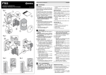
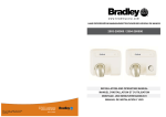
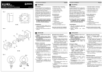
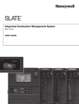
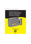
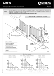
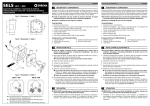
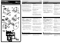
KLPMRG 012 Español Instrucciones de instalación 1 FOTOCÉLULA/ PHOTOCELLULE PHOTOCELL/ FOTOCÉLULA/ LICHTSCHRANKE MSL-045/01 1 DESCRIPCIÓN DESCRIPTION Advertencias Características Avertissements Caractéristiques Las fotocélulas KLPMRG012 están diseñadas para detectar obstáculos en instalaciones de puertas y portones automáticos, previniendo que la puerta colisione contra ellos. Se componen de un módulo emisor-receptor y un espejo. El módulo emite un rayo infrarrojo que se refleja en el espejo y regresa al módulo. Si el rayo no regresa al módulo, los contactos del relé de salida cambian de estado. • Salida libre de tensión mediante relé con contactos NC (normalmente cerrados) ó NO (normalmente abiertos) • Contactos del relé: 250Vac, 30Vdc, 3A máx. • Alimentación: 12-240Vdc; 24-240Vac (50/ 60Hz) • Distancia de detección: 12m (espejo ER4) Les photocellules KLPMRG012 sont conçues pour détecter des obstacles sur des installations de portes et de portails automatiques, en évitant ainsi que la porte les heurte. Elles sont composées d´un module émetteurrécepteur et d´un miroir. Le module émet un rayon infrarouge qui se reflète dans le miroir et qui retourne au module. Si le rayon ne retourne pas au module, les contacts du relais de sortie changent d´état. • Sortie libre de tension par relais avec contacts NC (normalement fermés) ou NO (normalement ouverts) • Contacts du relais: 250Vac, 30Vdc, 3A max. • Alimentation: 12-240Vdc; 24-240Vac (50/ 60Hz) • Distance de détection : 12m (miroir ER4) Contenido (fig. 1 y fig. 2) Instale y emplee el aparato respetando las indicaciones de estas instrucciones. El empleo inadecuado puede ser causa de averías y situaciones peligrosas. • • • • Cuerpo de la fotocélula (1) Soporte metálico (2) Espejo ER4 (3) Tornillos (4), arandelas (5) y tuercas (6) de fiajción al soporte • Prensaestopas (7), tapón (8), juntas (9) y (10) y arandela (11) Installez et utilisez l´appareil en respectant les indications de ces instructions. L´utilisation incorrecte peut provoquer des pannes et des situations dangereuses. 2 2 INSTALACIÓN Bornas 1 y 2: alimentación 12-240Vdc ó ecológica. Realice la instalación eléctrica siguiendo el reglamento de baja tensión y las normas aplicables. Consulte las instrucciones del cuadro de maniobra para realizar las conexiones. Montaje y conexionado (fig. 3) -FT (Test) + SNG2 V+ GND SNG1 SNG2 V+ GND SNG1 ENCODER2 ED 1 Elija una ubicación para la fotocélula y el espejo. Deben estar lo más alineados posible. La altura a la que deben instalarse las fotocélulas depende de cada instalación (consulte la normativa correspondiente). 2 Introduzca el cableado por el prensaestopas y realice las conexiones eléctricas. O Coloque correctamente el prensaestopas y el tapón para asegurar la estanqueidad. Cuadro de maniobra (ejemplo): VIVO-D201 AUX 24 Vdc 3 4 5 6 24-240Vac (50/60Hz) Bornas 3-5: contactos de relé NO Bornas 4-5: contactos de relé NC Coloque el espejo. Coloque el soporte y la fotocélula sin apretar completamente los tornillos. Coloque DIP1=ON. Conecte la alimentación y compruebe el funcionamiento de la fotocélula (DL1 permanece encendido cuando el rayo no se interrumpe, y se apaga cuando el rayo se interrumpe y no regresa a la fotocélula). écologique. Réalisez l´installation électrique en suivant le règlement de basse tension et les normes applicables. Consultez les instructions de l´armoire de commande pour réaliser les connexions. Montage et connexions (illustration 3) 1 Conecte la alimentación eléctrica. 2 Gire la fotocélula vertical (X) y horizontalmente (Y) para delimitar la zona de detección. 3 Fije la fotocélula en la posición central (O) de la zona de detección, apretando los tornillos correspondientes. • la alineación del haz infrarrojo • que la fotocélula o el espejo no han sufrido daños debido a la intemperie o a posibles agresiones de agentes externos Si les photocellules ne fonctionnent pas correctement, vérifiez les éléments suivants: • la tension d´alimentation de la photocellule • la position correcte de DIP1 P13 P14 P15 P16 P17 P18 P19 P20 P21 P22 P23 3 NO NC C KLPMRG012 P11 P12 LOCK 24V P9 P10 WARNING LIGHT FT2 P7 P8 STOP ST2 FT1 P4 P5 P6 GND FT1 ST1 P1 P2 P3 3 DIAGNÓSTICO DE AVERÍAS En caso de que las fotocélulas no funcionen correctamente, compruebe lo siguiente: • la tensión de alimentación de la fotocélula • la correcta posición de DIP1 Corps de la photocellule (1) Support métallique (2) Miroir ER4 (3) Vis (4), rondelles (5) et écrous (6) de fixation au support • Presse-étoupe (7), bouchon (8), joints (9) et (10) et rondelle (11) INSTALLATION Éliminez l´emballage de façon sûre et 1 Choisissez un emplacement pour la photocellule et le miroir. Ils doivent être le plus alignés possible. La hauteur à laquelle doivent être installées les photocellules dépend de chaque installation (consultez la réglementation correspondante). 2 Introduisez le câblage à travers le presseétoupe et réalisez les connexions électriques. O Placez correctement le presse-étoupe et le bouchon pour assurer l´étanchéité. Armoire de commande (exemple): VIVO-D201 Alineación del haz infrarrojo (fig. 2) • • • • • Protecteur de photocellule (réf. LPR100) • Protecteur miroir photocellule (réf. LPRER4) • Protector de fotocélula (ref. LPR100) • Protector de espejo fotocélula (ref. LPRER4) Elimine el embalaje de forma segura y Contenu (illustration 1 et illustration 2) Accessoires optionnels (non inclus) Accesorios opcionales (no incluidos) ENCODER1 Français Instructions d´installation Bornes 1 et 2: alimentation 12-240Vdc ou 24-240Vac (50/60Hz) Bornes 3-5: contacts de relais NO Bornes 4-5: contacts de relais NC 3 Placez le miroir. 4 Placez le support et la photocellule sans serrer complètement les vis. 5 Placez DIP1=ON. 6 Connectez l´alimentation et vérifiez le fonctionnement de la photocellule (DL1 reste allumé lorsque le rayon n´est pas interrompu, et s´éteint lorsque le rayon s´interrompt et ne retourne pas à la photocellule). Alignement du rayon infrarouge (illustration 2) 1 Connectez l´alimentation électrique. 2 Tournez la photocellule verticalement (X) et horizontalement (Y) pour délimiter la zone de détection. 3 Fixez la photocellule sur la position centrale (O) de la zone de détection, en serrant les vis correspondantes. DIAGNOSTIC DE PANNES • l´alignement du rayon infrarouge • que les photocellules ou le miroir n´aient pas souffert de dommages causés par l´intempérie ou de possibles agressions d´agents externes English Installation instructions 1 1 DESCRIPTION Português Instruções de instalação 1 DESCRIÇÃO Deutsch Installationsanweisungen BESCHREIBUNG Warnings Characteristics Advertências Características Warnhinweise Eigenschaften KLPMRG012 photocells are designed to detect ob s t a cl es i n a ut o m a t i c d oo r a n d g at e installations, preventing collision with the door/gate. They comprise an emitter-receiver module and a mirror. The module emits an infrared beam which is reflected in the mirror and returns to the module. If the beam does not return to the module, the output relay contacts change status. • Voltage-free output by way of relay with NC (normally closed) or NO (normally open) contacts. • Relay contacts: 250Vac, 30Vdc, 3A max. • Power supply: 12-240Vdc; 24-240Vac (50/ 60Hz) • Detection distance: 12m (mirror ER4) As fotocélulas KLPMRG012 foram concebidas para detectar obstáculos em instalações de portas e portões automáticos, evitando que a porta colida contra eles. Estão formadas por um módulo emissorreceptor e um espelho. O módulo emite um raio infravermelho que é reflectido no espelho e retorna ao módulo. Se o raio não retorna ao módulo, os contactos do relé de saída mudam de estado. • Saída livre de tensão através de relé com contactos NC (normalmente fechado) ou NO (normalmente aberto) • Contactos do relé: 250Vac, 30Vdc, 3A máx. • Alimentação: 12-240Vdc; 24-240Vac (50/ 60Hz) • Distância de detecção: 12m (espelho ER4) Die Lichtschranken KLPMRG012 wurden dafür konzipiert in automatischen Toranlagen Hindernisse zu erkennen und einen Zusammenstoß mit ihnen zu verhindern. Sie setzen sich aus einem SenderEm pfä ngerm odul sowie einem Spiegel zusammen. Das Modul sendet einen Infrarotstrahl, welcher vom Spiegel zum Modul zurück reflektiert. Wird der Strahl nicht zurück reflektiert, wechseln die Relais- Kontakte ihren Zustand. • Spannungsfreier Relais- Ausgang mit entweder NC-Kontakten (normalerweise geschlossen) oder NOKontakten (normalerweise geöffnet) • Relais- Kontakte: 250Vac, 30Vdc, 3A max. • Stromversorgung: 12-240Vdc; 24-240Vac (50/60Hz) • Reichweite: 12m (Spiegel ER4) Install and use the device in line with these instructions. Inappropriate use may lead to failures and hazardous situations. 2 Content (fig. 1 and fig. 2) • • • • Photocell casing (1) Metal bracket (2) Mirror ER4 (3) Screws (4), washers (5) and nuts (6) for attachment to the bracket • Gland (7), cap (8), seals (9) and (10) and washer (11) 1 Choose a location for the photocell and the mirror. They should be as aligned as possible. The height at which the photocells should be installed depends on each installation (check the corresponding legislation). 2 Introduce the cabling through the gland and make the electrical connections. O Correctly position the gland and the cap to ensure seal tightness. Operation panel (example): VIVO-D201 3 Acessórios opcionais (não incluídos) • Protector de fotocélula (ref. LPR100) • Protector espelho fotocélula (ref. LPRER4) 2 Terminals 1 and 2: power supply 12- 3 4 5 6 240(vdc) or 24-240Vac (50/60Hz) Terminals 3-5: NO relay contacts Terminals 4-5: NC relay contacts Position the mirror. Position the bracket and the photocell without fully tightening the screws. Position DIP1=ON. Connect the power supply and check the operation of the photocell (DL1 remains on when the beam is not interrupted, and goes off when the beam is interrupted and does not return to the photocell). Infrared beam alignment (fig. 2) 1 Connect the electrical power supply. 2 Turn the photocell vertically (X) and horizontally (Y) to delimit the detection area. 3 Secure the photocell in the central position (O) of the detection area, tightening the corresponding screws. e ecológica. Faça a instalação eléctrica segundo o regulamento de baixa tensão e as normas aplicáveis. Consulte as instruções do quadro de manobra para fazer as ligações. Montagem e ligações (fig. 3) 1 Escolha um local para a fotocélula e o espelho, que devem estar o mais alinhados possível. A altura em que as fotocélulas devem ser instaladas depende de cada instalação (consulte a normativa correspondente). 2 Introduza a cablagem pelo bucim e faça as ligações eléctricas. O Coloque correctamente o bucim e a tampa para assegurar a estanqueidade. Quadro de manobra (exemplo): VIVO-D201 • the alignment of the infrared beam • that the photocell and the mirror have not suffered any damage from the weather or from possible aggression by external agents Bornes 1 e 2: alimentação 12-240Vdc 3 4 5 6 ou 24-240Vac (50/60Hz) Bornes 3-5: contactos de relé NO Bornes 4-5: contactos de relé NC Coloque o espelho. Coloque o suporte e a fotocélula sem apertar completamente os parafusos. Coloque DIP1=ON. Ligue a alimentação e verifique o funcionamento da fotocélula (DL1 permanece aceso quando o raio não é interrompido, e apaga-se quando o raio é interrompido ou não retorna à fotocélula). Vorrichtung unter Beachtung der vorliegenden Anweisungen. Der unzweckmäßige Gebrauch kann zu Störungen und Gefahrsituationen führen. • • • • Lichtschranke (1) Metallhalterung (2) Spiegel ER4 (3) Schrauben (4), Scheiben (5) und Muttern (6) für die Befestigung • Kabeleinführung (7), Stöpsel (8), Dichtungsringe (9) und (10) und Scheibe (11) • Lichtschrankenschutz (Ref. LPR100) • Spiegel-Schutz (Ref. LPRER4) MONTAGE Verbindungsklemmen Entsorgen Sie die Verpackung auf eine sichere und umweltfreundliche Art und Weise. Führen Sie die elektrische Installation nach geltenden Bestimmungen aus. Um die Verbindungen sicher auszuführen konsultieren Sie bitte die Gebrauchsanweisung der Schalttafel. Montage und Anschluß (Abb. 3) 1 Faça a ligação da alimentação eléctrica. 2 Rode a fotocélula vertical (X) e horizontalmente (Y) para delimitar a área de detecção. 3 Prenda a fotocélula na posição central (O) da área de detecção, apertando os parafusos correspondentes. • o alinhamento do feixe infravermelho • se a fotocélula ou o espelho não sofreram estragos devido à intempérie ou a possíveis agressões de agentes externos Falls die Lichtschranken nicht richtig funktionieren, überprüfen Sie Folgendes: • Die Stromspannung der Lichtschranke • Die richtige Position von DIP1 Alinhamento do feixe infravermelho (fig. 2) Inhalt (Abb. 1 und Abb. 2) Zusatzausstattung (nicht inbegriffen) 1 Wählen Sie einen Standort für die Lichtschranke und den Spiegel. Sie sollten möglichst ebenmäßig angebracht werden. Die Höhe, in der die Lichtschranken angebracht werden sollten hängt von jeder Installation ab (sehen Sie bitte in entsprechender Regelung nach) 2 Führen Sie das Kabel in die Kabeleinführung ein und führen Sie die elektrischen Verbindungen durch. O Setzen Sie die Kabeleinführung sowie den Stöpsel richtig ein um die Dichtigkeit sicher zu stellen. Steuerung (Beispiel): VIVO-D201 3 DIAGNÓSTICO DE AVARIAS Se as fotocélulas não funcionam correctamente, verifique o seguinte: • a tensão de alimentação da fotocélula • a correcta posição de DIP1 Installieren und benutzen Sie diese 2 INSTALAÇÃO Elimine a embalagem de forma segura 3 FAILURE DIAGNOSIS Should the photocells not work correctly, check the following: • the power supply voltage of the photocell • the correct position of DIP1 Corpo da fotocélula (1) Suporte metálico (2) Espelho ER4 (3) Parafusos (4), anilhas (5) e porcas (6) de fixação no suporte. • Bucim (7), tampa (8), juntas (9) e (10) e anilha (11). • Photocell protector (ref. LPR100) • Mirror protector (ref. LPRER4) INSTALLATION Assembly and connections (fig. 3) indicações destas instruções. O uso inadequado pode causar avarias e situações perigosas. • • • • Optional accessories (not included) Discard the packaging safely and in an environmentally friendly manner. Complete the electrical installation in line with low voltage regulations and applicable rules. Check the instructions for the control panel in order to make the connections. Instale e use o aparelho respeitando as Conteúdo (fig. 1 e fig. 2) 3 4 5 6 1 und 2: Stromversorgung 12-240Vdc oder 24240Vac (50/60Hz) Verbindungsklemmen 3 -5: Relais Kontakte NO Verbindungsklemmen 4 -5: Relais Kontakte NC Setzen Sie den Spiegel ein. Befestigen Sie die Halterung sowie die Lichtschranke ohne die Schrauben ganz fest zu ziehen. Stellen Sie DIP1= ON Schließen Sie den Strom an und überprüfen Sie das Fnktionieren der Lichtschranke (DL1 leuchtet, wenn der Infrarotstrahl nicht unterbrochen wird und geht aus, wenn dieser unterbrochen wird und nicht zur Lichtschranke zurück kehrt). Ausrichtung des Infrarotstrahls (Abb. 2) 1 Schließen Sie den Stom an. 2 Drehen Sie die Lichtschranke senkrecht (X) und waagerecht (Y) um den Erkennungsbereich einzustellen. 3 Befestigen Sie die Lichtschranke mit Hilfe entsprechender Schrauben in der zentralen Position (O) des Erkennungsbereiches. STÖRUNGSSUCHE • Die Ausrichtung des Infrarotstrahls • Dass weder die LIchtschranke noch der Spiegel aufgrund von Witterung oder sonstigen äußeren Einflüssen Schaden genommen haben.