1
GAMIA MINI PLUS
GAMIA MINI
ISTRUZIONI DI MONTAGGIO
PRONTUARIO TECNICO
INSTRUCTIONS DE MONTAGE
PRECIS TECHNIQUE
INSTRUCCIONES PARA LA LOCACIÓN
MANUAL TÉCNICO
ASSEMBLY INSTRUCTIONS
TECHNICAL HANDBOOK
MONTAGEANLEITUNG
TECHNISCHE BESCHREIBUNG
Italiano
ISTRUZIONI DI POSA
Per procedere con maggiore ordine al montaggio della scala, consigliamo di iniziare avendo tutti gli attrezzi a disposizione.
Estrarre dallimballaggio tutti i componenti della scala e stenderli su unampia superficie in modo che siano ben visibili.
Legenda: L = larghezza A = alzata HT = altezza totale
Tutte le dimensioni sono espresse in centimetri.
ASSEMBLAGGIO DELLA SCALA:
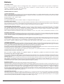
1) Calcolo dellalzata (A)
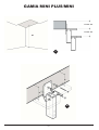
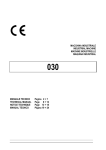
Misurare laltezza dal pavimento di partenza al pavimento di sbarco della scala HT (Fig.1). Sottrarre dall'altezza totale, il valore della prima alzata
fissa 21, quindi dividere il risultato ottenuto per il numero complessivo di gradini, considerando che la scala sbarca sempre sotto soletta.
Il valore ricavato deve essere compreso fra 20 e 24 cm.
Esempio: (280-21) = 259 (259:11) = 23.5
2) Calcolo ingombro scala
Per lingombro della scala in pianta, consultare le tabelle con i disegni dimensionali (pag. 34).
3) Fissaggio scala a soletta
Definire la posizione del supporto di sbarco nella soletta rispettando lalzata A calcolata precedentemente assicurando un buon livellamento del
piano del gradino (Fig.2). Forare in corrispondenza dei fori della piastra con punta Ø 14 mm e bloccare alla soletta il supporto utilizzando gli
appositi tiranti ad espansione. Inserire le 4 rondelle e le relative viti avvitandole poi alle boccole gradino.
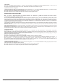
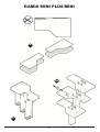
4) Assemblaggio componenti struttura
Completato il fissaggio del supporto di sbarco, assemblare a questo il successivo modulo intermedio in corrispondenza delle asole, con le apposite
viti e rondelle. Prima di bloccare completamente i supporti, regolare bene l'alzata facendo scorrere l'elemento in verticale.
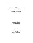
Procedere nello stesso modo con tutti i restanti moduli intermedi, quindi inserire in ognuno il tappo di chiusura in plastica (Fig.3).
Puntellare provvisoriamente la scala a metà rampa con un sostegno a terra.
(N.B.: Prestare particolare attenzione nella posa dei moduli, in modo che questi risultino perfettamente allineati fra loro).
5) Fissaggio scala a terra
Terminare la sequenza di assemblaggio dei supporti fino al modulo di partenza, assicurandosi del preciso posizionamento della scala rispetto
al vano, dopodiché segnare i punti di fissaggio della piastra a terra. Forare con punta Ø 14 mm e fissare il modulo di partenza al precedente
modulo intermedio quindi bloccare la piastra sul pavimento con appositi tiranti ad espansione (Fig.3).
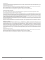
6) Fissaggio gradini
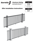
Definire lesatta sequenza dei gradini considerando che la pedata è alternata. (Per la conformazione esatta della scala, fare riferimento agli schemi
riportati a pag. 33). Utilizzare la dima in carta fornita per forare i gradini per il fissaggio dei moduli in corrispondenza delle boccole, come indicato
in (Fig.4). Fissare i gradini ai supporti con le viti autofilettanti in corrispondenza dei fori praticati (Fig.5).
N.B.: Fissare a parete la mensola gradino in corrispondenza della mezzeria della rampa, al fine di irrigidire la scala (Fig. 5a).
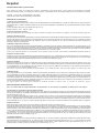
7) Montaggio pianerottolo
Per la foratura dell'eventuale pianerottolo, utilizzare la stessa dima del gradino rettilineo, facendo riferimento alla parte anteriore sagomata. (Fig.6).
Assemblare inizialmente il modulo pianerottolo con un modulo intermedio a formare la struttura completa del pianerottolo (Fig.7). Avvitare le
boccole, quindi fissare alla struttura della scala. Il pianerottolo non può essere mai in partenza o in arrivo.
N.B.: Orientare i componenti della struttura pianerottolo in funzione del senso di salita della scala.
Posizionare il pianerottolo sopra la struttura in corrispondenza dei fori precedentemente praticati, quindi tracciare e forare facendo riferimento
ai fori delle altre 4 boccole. Fissare gradino e struttura con le apposite viti autofilettanti (Fig.8).
La mensola pianerottolo viene utilizzata per supportare la scala quando con il pianerottolo subisce un cambio di direzione (Fig.9).
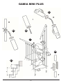
ASSEMBLAGGIO RINGHIERA GAMIA MINI PLUS:
N.B.: La scala va sempre montata con ringhiera oppure con supportini; i gradini non devono mai essere "liberi".
8) Punzonatura dei gradini e fissaggio nottolini
Per un corretto posizionamento della ringhiera, fare riferimento agli schemi riportati in (Fig.10), dove sono evidenziate le posizioni delle colonne.
La punzonatura sui gradini per il fissaggio della ringhiera va effettuata utilizzando la dima in carta precedentemente tagliata, seguendo le indicazioni
riportate in (Fig.11).
N.B.: Nel gradino di sbarco posizionare la punzonatura più vicina alla soletta 2 millemetri spostata verso l'interno del gradino, in modo che da
bordo gradino a punzonatura ci siano 22 mm (e non 20 come riporterebbe la punzonatura normale effettuata con la dima) (Fig.12).
IMPORTANTE! Una volta definita la posizione per la vite del nottolino sul gradino, forare con punta Ø 4 mm per una profondità di 3-4 cm (Fig.13).
Il nottolino del pianerottolo si fissa in asse ai nottolini dei gradini precedente e successivo.
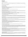
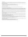
9) Fissaggio colonne
Predisporre su tutte le colonne la cima coi vari componenti, come mostra la (Fig.14).
Partendo dal basso, posizionare provvisoriamente la prima, la seconda e la terza colonna inserendole nei nottolini, facendo attenzione che la
seconda e la terza colonna siano a filo rispetto al sotto dei gradini. L'altezza X misurata fra la seconda e la terza colonna, determina la misura a
cui dovrà essere tagliata la prima colonna (Fig.15), che sarà poi fissata a terra tramite il bicchiere (Fig.16). Bloccare le colonnine al nottolino con
l'apposita vite (Fig.17). Procedere con l'assemblaggio di tutte le colonne e chiuderle sotto con i tappini in plastica.
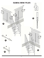
Per dare maggiore rigidità alla ringhiera nell'ultima colonnina viene applicato un ulteriore nottolino da fissare alla soletta (Fig.18 - B e 19). Per
l'eventuale ringhiera esterna del pianerottolo, vedere gli schemi riportati in (Fig.21). La colonnina interna del pianerottolo va giuntata con un'ulteriore
colonna precedentemente tagliata a misura (Fig.25 - F).
10) Assemblaggio corrimano
Assemblare i corrimani tramite la barra filettata e la rondella (Fig. 20 - A). Fissare le colonne al corrimano tramite le apposite viti autofilettanti
come mostra la (Fig. 14). Applicare il tappo nelle parti terminali del corrimano (Fig. 22 - C). Per collegare la ringhiera della prima rampa
con la ringhiera della seconda rampa utilizzare l'anello colonna e fissarlo tramite l'apposito raccordo e tappo corrimano (Fig. 23 - D). La ringhiera
esterna nel caso di presenza di pianerottolo va collegata come indicato in (Fig. 24 - E).
Rintal S.p.a
1
Revisione 1 - 16/05/05
11) Balaustra
Gli schemi di montaggio riportati a pagina 21 , mostrano i casi più frequenti di montaggio per l'eventuale balaustra (Fig.26, 27, 28 - G, 30 - H).
Per irrigidire tratti di balaustra superiore ad un metro, utilizzare la colonna stop come indicato in (Fig.29).
12) Eventuale assenza di ringhiera
I supporti di irrigidimento scala, sono costituiti da tratti di colonna di lunghezze Y e W in funzione dell'alzata calcolata (Fig. YY) e devono essere
chiusi sopra e sotto con gli appositi tappini in plastica.
Nei modelli venduti in kit, i supportini sono ricavati tagliando a misura le colonne della ringhiera.
Nei modelli venduti non in kit, i supporti sono già forniti, ma devono essere tagliati a misura.
ASSEMBLAGGIO RINGHIERA GAMIA MINI:
N.B.: La scala va sempre montata con ringhiera oppure con supportini; i gradini non devono mai essere "liberi".
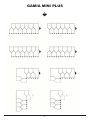
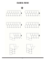
13) Punzonatura dei gradini e fissaggio nottolini
Per un corretto posizionamento della ringhiera, fare riferimento agli schemi riportati in (Fig.31), dove sono evidenziate le posizioni delle colonne
in funzione del numero di gradini (pari o dispari) o della conformazione della scala. La disposizione delle colonnine nel caso di scale con giro, è
obbligata dalla colonnina in angolo, posta sulla parte interna del pianerottolo (posizione indispensabile per il collegamento fra gradini e pianerottolo).
Le colonnine dell'eventuale ringhiera esterna vanno posizionate esattamente in corrispondenza di quelle sul lato interno, di conseguenza il
fissaggio al gradino è spostato di mezza pedata.
La punzonatura sui gradini per il fissaggio della ringhiera va effettuata utilizzando la dima in carta precedentemente tagliata, seguendo le indicazioni
riportate in (Fig.32).
N.B.: Nel caso in cui nel gradino di sbarco occorra effettuare due punzonature, posizionare quella più vicina alla soletta 2 millemetri spostata
verso l'interno del gradino, in modo che da bordo gradino a punzonatura ci siano 22 mm (e non 20 come riporterebbe la punzonatura normale
effettuata con la dima) (Fig.33).
IMPORTANTE! Una volta definita la posizione per la vite del nottolino sul gradino, forare con punta Ø 4 mm per una profondità di 3-4 cm (Fig.34).
Il nottolino del pianerottolo si fissa in asse ai nottolini dei gradini precedente e successivo.
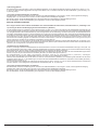
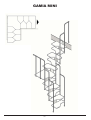
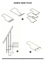
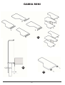
14) Fissaggio colonne
Predisporre su tutte le colonne intermedie (quelle a "L") il nottolino coi vari componenti, come mostra la (Fig.35).
Partendo dal basso, posizionare provvisoriamente la prima, la seconda e la terza colonna inserendole nei nottolini, facendo attenzione che la
seconda e la terza colonna siano a filo rispetto al piano inferiore dei gradini.
L'altezza X misurata fra la seconda e la terza colonna, determina la misura a cui dovrà essere tagliata la prima colonna (Fig.36), che sarà poi
fissata a terra tramite il bicchiere (Fig.37).
Bloccare le colonnine al nottolino con l'apposita vite (Fig.38).
Procedere con l'assemblaggio di tutte le colonne intermedie e chiuderle "sotto" con i tappini in plastica.
Nel caso in cui l'ultima colonna sia vicino alla soletta, applicare un nottolino contro la soletta per dare maggiore rigidità alla colonna (Fig.39 - I).
Nella soluzione in cui l'ultima colonnina sia sul pavimento, fissare questa tramite il bicchiere (Fig.40 e Fig.37 - L).
Per l'eventuale ringhiera esterna del pianerottolo, vedere gli schemi riportati in (Fig.41 e Fig. 42 - M). La colonnina interna del pianerottolo va
giuntata con un'ulteriore colonna precedentemente tagliata a misura (Fig. 43 - N).
15) Eventuale assenza di ringhiera
I supporti di irrigidimento scala, sono costituiti da tratti di colonna di lunghezze Y e W in funzione dell'alzata calcolata (Fig. WW) e devono essere
chiusi sopra e sotto con gli appositi tappini in plastica.
Nei modelli venduti in kit, i supportini sono ricavati tagliando a misura le colonne della ringhiera.
Nei modelli venduti non in kit, i supporti sono già forniti, ma devono essere tagliati a misura.
Rintal S.p.a
2
Revisione 1 - 16/05/05
Français
INSTRUCTIONS POUR LA POSE
Afin de procéder à un montage correct de lescalier, nous vous conseillons de commencer avec tous les outils nécessaires placés devant vous.
Extraire de lemballage tous les composants de lescalier et placer les bien en vue sur une grande surface.
Légende : L = largeur A = contremarche HT = hauteur totale
Toutes les dimensions sont exprimées en centimètres.
ASSEMBLAGE DE LESCALIER :
1) Calcul de la contremarche (A)
Mesurer la hauteur du sol du point de départ jusquà la fin de lescalier HT (Fig.1). Soustraire, de la hauteur totale, la valeur de la première
contremarche fixée à 21cm, par conséquent, diviser le résultat obtenu par le nombre total de marches en tenant compte que lescalier se termine
toujours sous la dalle.
La valeur obtenue doit être comprise entre 20 et 24 cm.
Exemple : (280-21) = 259 (259:11) = 23.5
2) Calcul des dimensions de lescalier
En ce qui concerne les dimensions de lescalier sur plan, consulter les tableaux ainsi que les dessins dimensionnels (pag. 34).
3) Fixation de lescalier à la dalle
Définir la position du support darrivée dans la dalle en respectant la contremarche A calculée précédemment tout en ayant un bon nivellement
du plan de la marche (Fig.2).Forer en fonction des trous de la plaque avec un foret de Ø 14 mm et bloquer à la dalle le support à laide des tirants
à détente. Fixer les bagues en plastique dans les 4 trous supérieurs du module, en utilisant les rondelles et les écrous hexagonaux.
4) Assemblage des composants de la structure
Une fois la fixation du support darrivée terminée, assembler à celui-ci le module intermédiaire suivant en fonction des fentes à laide des vis et
des rondelles correspondantes. Avant de bloquer complètement les supports, régler bien la hauteur de la contremarche en faisant coulisser
lélément à la verticale. Procéder de la même façon avec tous les modules intermédiaires restants, par conséquent, insérer dans chacun deux
le bouchon de fermeture en plastique (Fig.3). Chevaler, de façon provisoire, lescalier à mi-volée avec un support au sol.
(N.B.: Faire attention lors de la pose aux modules afin quils restent parfaitement alignés entre eux).
5) Fixation de lescalier au sol
Terminer lassemblage des supports jusquau module de départ en vous assurant du positionnement précis de lescalier par rapport à la cage,
et ensuite marquer les points de fixation de la plaque au sol. Forer avec un foret de Ø 14 mm et fixer le module de départ au module intermédiaire
précédent puis bloquer la plaque au sol à laide des tirants spéciaux à détente (Fig.3).
6) Fixation des marches
Définir la séquence exacte des marches en sachant que la marche est alternée. (Pour la disposition exacte de lescalier, se référer aux schémas
reportés à la pag. 33). Utiliser le gabarit en papier fourni pour forer les marches pour la fixation des modules en fonction des bagues, comme
indiqué à la (Fig.4). Fixer les marches aux supports à laide des vis-taraud fonction des trous effectuées (Fig.5).
N.B.: Fixer au mur la console pour la marche dans le milieu de la volée, afin de raidir lescalier (Fig. 5a).
7) Montage du palier
Pour le forage du palier éventuel, utiliser le même gabarit de la marche rectiligne en se référant à la partie profilée anteriéure (Fig.6). Assembler
tout dabord le module du palier à un module intermédiaire afin de former la structure complète du palier (Fig.7). Visser les bagues et ensuite,
fixer à la structure de lescalier. Le palier ne peut jamais être au départ ou à larrivée.
N.B.: Orienter les composants de la structure du palier en fonction du sens de la montée de lescalier.
Positionner le palier au-dessus de la structure en fonction des trous effectués précédemment, par conséquent, tracer et forer en se référant aux
trous des 4 autres bagues. Fixer la marche et la structure à laide des vis-taraud spéciales (Fig.8).
Le console du palier est utilisée pour supporter lescalier lorsque le palier subit un changement de direction (Fig.9).
ASSEMBLAGE RAMPE GAMIA MINI PLUS:
N.B. : Lescalier doit être toujours monté ou avec la rampe ou avec les supports; les marches ne doivent jamais être « libres »
8) Poinçonnage des marches et fixation des cliquets «nottolini»
Pour un positionnement correct de la rampe, se référer aux schémas reportés à la (Fig.10), où les positions des balustres sont mises en évidence.
Le poinçonnage sur les marches, pour la fixation de la rampe, seffectue en utilisant le gabarit en papier coupé précédemment selon les indications
reportées à la (Fig.11). N.B.: Dans la marche darrivée, positionner le poinçonnage plus près de la dalle déplacé de 2 millimètres vers lintérieur
de la marche de façon à que du bord de la marche au poinçonnage il y ait 22 mm (et pas 20 comme le poinçonnage normal reporte lorsquil
est effectué avec le gabarit) (Fig.12).
IMPORTANT! Une fois la position définie pour les vis du cliquet sur la marche, forer avec un foret de Ø 4 mm pour une profondeur de 3-4 cm
(Fig.13). Le cliquet du palier se fixe en axe avec les cliquets des marches précédente et suivante.
9) Fixation des balustres
Prédisposer, sur tous les balustres intermédiaires, la «cima» avec les différents composants comme illustré à la (Fig.14).
En partant du bas, positionner, de façon provisoire, le premier, le second et le troisième balustre en les insérant dans les cliquets et tout en faisant
attention à ce que le second et le troisième balustres soient alignés par rapport au-dessous des marches. La hauteur X mesurée entre le second
et le troisième balustre détermine la mesure où le premier balustre doit être coupé (Fig.15) et qui sera ensuite fixé au sol à laide du gobelet
(Fig.16). Bloquer les colonnettes au cliquet à laide de la vis spéciale (Fig.17). Procéder par lassemblage de tous les balustres intermédiaires
et les fermer en dessous avec les bouchons en plastique. Pour donner plus de rigidité à la rampe, dans la dernière colonnette on applique un
autre cliquet à fixer à la dalle (Fig.18 B et 19). Pour léventuelle rampe externe au palier, consulter les schémas reportés aux (Fig. 21). La
colonnette interne du palier doit être jointe au dernier balustre coupé précédemment sur mesure (Fig. 25 - F).
10) Assemblage de la main courante
Assembler les mains courantes à laide de la barre filetée et la rondelle (Fig. 20 - A). Fixer les balustres à la main courante à laide des vis-taraud
correspondantes comme illustré à la (Fig. 14). Appliquer le bouchon dans les parties terminales de la main courante (Fig. 22 - C). Pour joindre
la rampe de la première volée à la rampe de la seconde volée, utiliser lanneau du balustre et fixer le à laide du raccord spécial et du bouchon
de la main courante (Fig. 23 - D). La rampe externe doit être jointe comme indiqué à la (Fig. 24 E) et lorsquil y a un palier.
Rintal S.p.a
3
Revisione 1 - 16/05/05
11) Garde-corps
Les schémas de montage reportés à la page 21 illustrent les cas les plus fréquents de montage pour le garde-corps éventuel (Fig.26, 27, 28 G, 30 - H). Pour raidir les sections de garde-corps supérieur à un mètre, utiliser la «colonna stop» comme indiqué à la (Fig.29).
12) Eventuelle absence de rampe
Les supports de raidissement escalier se composent de pièces de balustre de longueurs Y et W par rapport à la hauteur de marché calculée
(Fig. YY) et doivent être fermés au-dessus et au-dessous avec les spéciaux bouchons en plastique.
Dans les modèles vendus en kit, les petits supports sont obtenus en coupant sur mesure les balustres.
Dans les modèles vendus non en kit, les supports sont déjà pourvus, mais ils doivent être coupés sur mesure.
ASSEMBLAGE RAMPE GAMIA MINI:
N.B. : Lescalier doit être toujours monté ou avec la rampe ou avec les supports; les marches ne doivent jamais être « libres »
13) Poinçonnage des marches et fixation des cliquets «nottolini»
Pour un positionnement correct de la rampe, se référer aux schémas reportés à la (Fig.31), où les positions des balustres sont mises en évidence
en fonction du nombre de marches (pair ou impair) ou de la conformation de lescalier. La disposition des colonnettes pour les escaliers tournants
est donnée par la colonnette en angle placée sur la partie interne du palier (position indispensable pour la jonction entre les marches et le palier).
Les colonnettes de la rampe externe éventuelle doivent être positionnées exactement en fonction des colonnettes du côté interne, par conséquent,
la fixation à la marche est déplacée dune demi marche. Le poinçonnage sur les marches, pour la fixation de la rampe, seffectue en utilisant
le gabarit en papier coupé précédemment selon les indications reportées à la (Fig.32).
N.B.: Si deux poinçonnages sont nécessaires dans la marche darrivée, positionner le plus près à la dalle déplacé de 2 millimètres vers lintérieur
de la marche de façon que du bord de la marche au poinçonnage il y ait 22 mm (et pas 20 comme le poinçonnage normal reporte lorsquil est
effectué avec le gabarit) (Fig.33).
IMPORTANT! Une fois la position définie pour les vis du cliquet sur la marche, forer avec un foret de Ø 4 mm pour une profondeur de 3-4 cm
(Fig.34). Le cliquet du palier se fixe dans le prolongement des cliquets des marches précédente et suivante.
14) Fixation des balustres
Prédisposer, sur tous les balustres intermédiaires (ceux en "L"), le cliquet avec les différents composants comme illustré à la (Fig.35).
En partant du bas, positionner, de façon provisoire, le premier, le second et le troisième balustre en les insérant dans les cliquets et tout en
faisant attention à ce que le second et le troisième balustres soient alignés par rapport au dessous des marches.
La hauteur X mesurée entre le second et le troisième balustre détermine la mesure où le premier balustre doit être coupé (Fig.36) et qui sera
ensuite fixé au sol à laide du gobelet (Fig.37). Bloquer les colonnettes au cliquet à laide de la vis spéciale (Fig.38).
Procéder par lassemblage de tous les balustres intermédiaires et les fermer en dessous avec les bouchons en plastique.
Si le dernier balustre est près de la dalle, appliquer un cliquet contre la dalle pour donner plus de rigidité au balustre (Fig.39 - I). Dans le cas
la dernier pilier est au sol, fixer ce derniere à laide du gobelet (Fig.40 et Fig.37 - L). Pour l'éventuelle rampe externe au palier, consulter les
schémas reportés aux (Fig.41 et Fig.42 - M). La colonnette interne du palier doit être jointe au dernier balustre coupé précédemment sur mesure
(Fig.43 - N).
15) Eventuelle absence de rampe
Les supports de raidissement escalier se composent de pièces de balustre de longueurs Y et W par rapport à la hauteur de marché calculée
(Fig. WW) et doivent être fermés au-dessus et au-dessous avec les spéciaux bouchons en plastique.
Dans les modèles vendus en kit, les petits supports sont obtenus en coupant sur mesure les balustres.
Dans les modèles vendus non en kit, les supports sont déjà pourvus, mais ils doivent être coupés sur mesure.
Rintal S.p.a
4
Revisione 1 - 16/05/05
Español
INSTRUCCIONES PARA LA COLOCACIÓN
Para realizar con orden el montaje de la escalera, aconsejamos comenzar teniendo a mano todas las herramientas necesarias.
Sacar del embalaje todos los componentes de la escalera y extenderlos sobre una amplia superficie para que estén bien visibles.
Leyenda: L = ancho A = contrahuella HT = altura total
Todas las dimensiones están expresadas en centímetros.
MONTAGE DE LA ESCALERA:
1) Cálculo de la contrahuella (A)
Medir la altura desde el suelo de inicio hasta el suelo del desembarque de la escalera HT (Fig.1). Restar de la altura total, el valor de la primera
contrahuella fija 21 y dividir el resultado obtenido por el número total de peldaños, considerando que la escalera desembarca siempre debajo
de la losa.
El valor alcanzado debe estar comprendido entre 20 y 24 cm.
Ejemplo: (280-21) = 259 (259:11) = 23.5
2) Cálculo dimensiones escalera
Para las dimensiones de la escalera en planta, consultar las tablas que contienen los diseños con las dimensiones (pág. 34).
3) Fijación escalera a la losa
Definir la posición del soporte de desembarque en la losa respetando la contrahuella A calculada anteriormente, asegurando la buena nivelación
del plano del escalón (Fig.2). Agujerear en correspondencia con los orificios de la chapa con una punta de Ø 14 mm y bloquear a la losa el
soporte, utilizando los específicos tirantes de expansión. Fijar los bujes de plástico en los 4 orificios superiores del módulo, utilizando las
arandelas y las tuercas hexagonales.
4) Montaje componentes estructura
Una vez completada la fijación del soporte de desembarque, ensamblar a éste el siguiente módulo intermedio en correspondencia con las
ranuras, con los respectivos tornillos y arandelas. Antes de bloquear completamente los soportes, regular bien la contrahuella haciendo deslizar
el elemento en vertical. Proceder del mismo modo con los restantes módulos intermedios y insertar en cada uno el tapón de cierre de plástico
(Fig.3). Apuntalar de forma provisoria la escalera a mitad del tramo con un soporte a suelo.
(Nota: Poner especial atención en la colocación de los módulos, para que éstos se encuentren perfectamente alineados entre sí).
5) Fijación escalera al suelo
Finalizar la secuencia de ensamblado de los soportes hasta el módulo de inicio, asegurándose el posicionamiento preciso de la escalera con
respecto al espacio, después de lo cual señalar los puntos de fijación de la placa a tierra. Agujerear con una punta Ø 14 mm y fijar el módulo
de inicio al módulo anterior bloqueando la placa al suelo con los tirantes de expansión (Fig.3).
6) Fijación peldaños
Definir la secuencia de los escalones considerando que la huella es alternada. (Sobre la conformación exacta de la escalera, tomar como
referencia los esquemas de la Pág. 33). Utilizar la plantilla de papel suministrada para agujerear los peldaños para la fijación de los módulos
en correspondencia con los casquillos, como se indica en la (Fig.4). Fijar los peldaños a los soportes con los tornillos autorroscantes en
correspondencia con los orificios realizados (Fig.5).
N.B.: Fije a la pared la repisa peldaño en correspondecia con la mitad del tramo, para dar mayor rigidez a la escalera (Fig. 5a).
7) Montaje rellano
Para el agujereado de un eventual rellano, utilizar la misma plantilla del peldaño recto, tomando como referencia la parte anterior en forma.
(Fig.6). Ensamblar al comienzo el módulo rellano con un módulo intermedio para formar la estructura completa del rellano (Fig.7). Enroscar
los casquillos, después fijar a la estructura de la escalera. El rellano nunca puede estar en el inicio o en la salida. Nota: Orientar los componentes
de la estructura rellano en función del sentido de subida de la escalera. Posicionar el rellano encima de la estructura en correspondencia con
los orificios antes realizados y trazar y agujerear tomando como referencia los orificios de los otros 4 casquillos. Fijar el peldaño y la estructura
con los correspondientes tornillos autorroscantes (Fig.8).
La repisa rellano se utiliza para sostener la escalera cuando el rellano sufre un cambio de dirección (Fig.9).
MONTAJE BARANDA GAMIA MINI PLUS:
N.B. : La escalera debe ser siempre montada o con la baranda o con los soportes; los peldaños no deben nunca estar libres.
8) Punzonado de los peldaños y fijación retenes nottolini
Para un posicionamiento correcto de la baranda tomar como referencia los esquemas de la (Fig.10), donde se indican las posiciones de los
barrotes. El punzonado de los peldaños para la fijación de la baranda se realiza utilizando la plantilla de papel cortado con anterioridad, siguiendo
las indicaciones de la (Fig. 11).
Nota: En el peldaño de desembarque posicionar el punzonado más cercano a la losa 2 milímetros desplazado hacia el interior del peldaño,
para que desde el borde del peldaño hasta el punzonado haya 22 mm (y no 20 como indicaría un punzonado normal realizado con la plantilla
(Fig.12). ¡IMPORTANTE! Una vez definida la posición para el tornillo del retén nottolino en el peldaño, agujerear con una punta de Ø 4 mm,
una profundidad de 3-4 cm (Fig.13). El retén nottolino del rellano se fija en eje a los retenes nottolini de los peldaños anterior y siguiente.
9) Fijación barrotes
Disponer en todos los barrotes la cima con los distintos componentes, según lo muestra la (Fig.14).
Comenzando desde abajo, posicionar de forma provisoria el primero, el segundo y el tercer barrote introduciéndolos en los retenes nottolini,
prestando atención para que el segundo y tercer barrote estén a nivel con respecto a la parte de abajo de los peldaños. La altura X medida
entre el segundo y tercer barrote determina la medida a la cual deberá ser cortado el primer barrote (Fig. 15) que se fijará luego a tierra mediante
el vaso (Fig.16). Bloquear los barrotes al retén nottolino con el correspondiente tornillo (Fig.17). Realizar el ensamblado de todos los barrotes
y cerrar debajo con los tapones de plástico. Para dar mayor rigidez a la baranda en el último barrote se aplica otro retén nottolino que se fija
a la losa (Fig.18 - B y 19). Para colocar una baranda externa al rellano, ver los esquemas de la (Fig. 21). El barrote interno del rellano se junta
utilizando un barrote cortado a medida (Fig.25 - F).
10) Montaje pasamanos
Ensamblar los pasamanos con la barra roscada y la arandela (Fig. 20 - A). Fijar los barrotes al pasamano mediante los correspondientes tornillos
autorroscantes según lo muestra la (Fig. 14). Aplicar el tapón en las partes terminales del pasamano (Fig. 22 - C). Para conectar la baranda
del primer tramo con la baranda del lo segundo tramo utilizar el anillo barrote y fijarlo mediante el codo y tapón pasamanos (Fig. 23 - D). La
baranda externa, si existe un rellano, se conecta como lo indica la (Fig. 24 E).
Rintal S.p.a
5
Revisione 1 - 16/05/05
11) Balaustrada
Los esquemas de montaje de la Pág. 21, muestran los casos más frecuentes de montaje si hay una balaustrada (Fig.26, 27, 28 - G, 30 - H).
Para fijar piezas de balaustrada superiores a un metro, utilizar la colonna stop como lo indica la (Fig.29).
12) Eventual ausencia de baranda
Los soportes de renfuerzo escalera se componen de piezas de barrotes de largos Y y W en función de la altura del peldaño calculada (Fig. YY)
y tienen que ser cerrados sobre y abajo con los expresos tapones de plástico.
Por los modelos vendidos en kit, los soportes son obtenidos cortando a la medida los barrotes de la baranda.
Por los modelos no vendidos en kit, los soportes son ya aprovisionados, pero tienen que ser cortados a la medida.
MONTAJE BARANDA GAMIA MINI:
N.B. : La escalera debe ser siempre montada o con la baranda o con los soportes; los peldaños no deben nunca estar libres.
13) Punzonado de los peldaños y fijación retenes nottolini
Para un posicionamiento correcto de la baranda, tomar como referencia los esquemas de la (Fig. 31) donde se evidencian las posiciones de
las columnas en función del número de peldaños (pares o impares) o de la conformación de la escalera. La disposición de los barrotes en caso
de escaleras con vuelta es obligatoria para el barrote en ángulo, colocado en la parte interior del rellano (posición indispensable para la conexión
entre los peldaños y el rellano). Los barrotes de la posible baranda externa se posicionan exactamente en correspondencia con los del lado
interno, en consecuencia la fijación al peldaño se desplaza media huella.
El punzonado de los peldaños para la fijación de la baranda se realiza utilizando la plantilla de papel cortada con anterioridad, siguiendo las
indicaciones de la (Fig. 32).
Nota: Si en el peldaño de desembarque se deben realizar dos punzonados, posicionar el más cercano a la losa 2 milímetros desplazado hacia
el interior del peldaño, para que desde el borde del peldaño hasta el punzonado haya 22 mm (y no 20 como indicaría un punzonado normal
realizado con la plantilla (Fig.33).
¡IMPORTANTE! Una vez definida la posición para el tornillo del retén nottolino en el peldaño, agujerear con una punta de Ø 4 mm, una
profundidad de 3-4 cm (Fig.34). El retén nottolino del rellano se fija en eje a los retenes nottolini de los peldaños anterior y siguiente.
14) Fijación barrotes
Predisponer en todos los barrotes intermedios (aquellos en "L") el retén nottolino con los diferentes componentes, según lo muestra la (Fig.35).
Comenzando desde abajo, posicionar de forma provisoria el primero, el segundo y el tercer barrote introduciéndolos en los retenes "nottolini",
prestando atención para que el segundo y tercer barrote estén a nivel con respecto a la parte de abajo de los peldaños.
La altura X medida entre el segundo y tercer barrote determina la medida a la cual deberá ser cortado el primer barrote (Fig.36) que se fijará
luego a tierra mediante el vaso (Fig.37).
Bloquear los barrotes al retén "nottolino" con el correspondiente tornillo (Fig.38).
Realizar el montaje de todos los barrotes intermedios y cerrarlos por debajo con los tapones de plástico.
Si el último barrote está cerca de la losa, aplicar un retén "nottolino" contra la losa para dar mayor rigidez al barrote (Fig.39 - I). En la solución
con el último barrote al suelo, fijar éste mediante el vaso (Fig.40 y Fig.37 - L).
Para una eventual baranda externa al rellano, ver los esquemas de las (Fig.41 y Fig. 42 M). El barrote interno del rellano se junta utilizando
un barrote cortado a medida antecedentemente (Fig. 43 - N).
15) Eventual ausencia de baranda
Los soportes de renfuerzo escalera se componen de piezas de barrotes de largos Y y W en función de la altura del peldaño calculada (Fig. WW)
y tienen que ser cerrados sobre y abajo con los expresos tapones de plástico.
Por los modelos vendidos en kit, los soportes son obtenidos cortando a la medida los barrotes de la baranda.
Por los modelos no vendidos en kit, los soportes son ya aprovisionados, pero tienen que ser cortados a la medida.
Rintal S.p.a
6
Revisione 1 - 16/05/05
English
ASSEMBLY INSTRUCTIONS
In order to assemble the staircase with the greatest possible ease, we advise you to begin the installation with all the necessary equipment on
hand.
Remove all the parts of the staircase from the packaging and lay them on a large surface so that they are all visible.
Key: L = width A = rise HT = total height
All dimensions are given in centimetres.
STAIRCASE ASSEMBLY:
1) Calculation of the rise (A)
Measure the height from the starting floor to the stair end landing floor HT (Fig.1). Subtract the value of the first fixed rise 21 from the total height
then divide the result obtained by the total number of steps, bearing in mind that the stair always finishes below the floor level.
The value obtained must always be between 20 and 24 cm.
Example: (280-21) = 259 (259:11) = 23.5
2) Calculation of staircase dimensions
For the overall dimensions of the stair, consult the tables with the dimension drawings (page 34).
3) Fixing of the staircase to the slab
Define the position of the landing support on the slab, respecting the rise A, previously calculated ensuring a good leveling of the step (Fig.2).
Drill correspondently to the holes in the plate with a Ø 14 mm drill and block the support to the slab using the proper expansion. Fasten the
plastic blushs in the 4 top holes of the support, using the washers and the hexagon nuts.
4) Assembly of the structure components
Once having fixed of the landing support, assemble the next intermediate module to it, in correspondence with the holes using the appropriate
screws and washers. Before securing the supports completely, adjust the rise by sliding the part vertically.
Proceed in the same way with all the remaining intermediate modules, then insert the plastic closure cap into each one (Fig.3).
Place a provisional prop half way up the flight with a support post.
(N.B.: Pay close attention when fitting the modules to ensure that they are perfectly aligned).
5) Fixing of the staircase to the floor
Complete the assembly of the supports till the starting module, ensuring that the staircase has been precisely positioned with respect to the
stair well, then mark out the points for fixing the plate to the floor. Drill holes using a Ø 14 mm bit and fix the starting module to the previous
intermediate module, then securing the plate to the ground using the appropriate expanding tie-rods. (Fig.3).
6) Fixing of the steps
Define the exact sequence of the steps, taking into consideration that the steps alternate. (For the staircases exact configuration, refer to the
diagrams shown on page 33). Use the paper template supplied to make holes in the steps for the fixing of the modules in correspondence with
the bushes as shown in (Fig.4). Fix the steps to the supports using the self-threading screws in correspondence with the holes made (Fig.5).
N.B.: Fix to the wall the step bracket in the middle of the flight, in order to make the stair stiff (Fig. 5a).
7) Mounting the platform
For making the holes for a platform (if present), use the same template as the straight step, referring to the previous shaped part. (Fig.6). First
assemble the landing module with an intermediate module in order to make the complete landing structure (Fig.7). Tighten the bushes platform,
then fix to the staircase structure.
The platform cannot be placed at the starting or landing point of the staircase.
N.B.: Orientate the components of the landing structure according to the sense of climbing of the stair.
Position the platform above the structure in correspondence with the previously made holes, then trace out and drill holes using the other 4
bushes as a reference point. Fix both step and structure using the appropriate self-threading screws (Fig.8). The landing bracket is used to
support the staircase when the landing changes direction (Fig.9).
GAMIA MINI PLUS RAILING ASSEMBLY:
N.B.: The stair has to be always assembled with the railing or with the little supports; the steps cant never be free.
8) Punching of steps and fixing the pawls
For a correct positioning of the handrail, refer to the diagrams shown in (Fig.10), where the positions of the columns are shown.
The punching on the steps for fixing the railing must be carried out using the previously cut paper template, following the indications shown in
(Fig.11). N.B.: On the landing step, position the punching closest to the floor, 2mm further towards the step so that there are 22mm from the
edge of the step to the punched hole (not 20 as normal punching carried out using the template would produce) (Fig.12).
IMPORTANT! Once the position for the pawl screw has been defined on the step, make a hole using a Ø 4 mm bit with a depth of 3-4 cm (Fig.13).
The pawl of the landing is fixed on an axis to the pawls components of the previous and next steps.
9) Fixing of the balusters
Attach the cima connectors with its various components to all balusters as shown in (Fig.14).
Starting from the bottom, provisionally position the first, the second and the third balusters inserting them into the pawls components, ensuring
that the second and the third balusters are flush with the underside of the step. Height X measured between the second and the third baluster
determines the measurement to which the first baluster must be cut (Fig.15), which will then be fixed to the floor using the bells (Fig.16). Secure
the balusters using the appropriate screw (Fig.17).
Proceed with the assembly of all the intermediate balusters and close underneath using the plastic caps.
In order to provide the railing with greater rigidity, a further pawl, is applied to the last baluster, which should be fixed to the slab (Fig.18 - B
and 19). In case there is an external railing for the landing, see the diagrams shown in (Fig.21). The internal baluster of the landing should be
joined with a further baluster previously cut to the right size (Fig.25 - F).
10) Assembly of the handrail
Assemble the handrails using the threaded rod and washer (Fig. 20 - A). Fix the balusters to the handrail by means of the appropriate selfthreading screws as shown in (Fig. 14). Apply the caps to the ends of the handrail (Fig. 22 - C). To connect the handrail of the first flight to the
handrail of the second flight, use the baluster ring and fix it with the appropriate connector and handrail cap (Fig. 23 - D). Where a landing is
present, the external railing should be connected as shown in (Fig. 24 - E).
Rintal S.p.a
7
Revisione 1 - 16/05/05
11) Balustrade
The assembly diagrams shown on page 21 show the most common types of assembly for any balusters present (Fig.26, 27, 28 - G, 30 - H).
In order to give greater rigidity to the section of balustrade that are more than one metre long, use the colonna stop as indicated in (Fig.29).
12) Eventual absence of railing
The supports for the stiffening of the stair are composed by pieces of balusters of Y and W lenghts according to the calculated riser (Fig. YY)
and they have to be closed on the top and on the bottom with the proper plastic caps.
In the models sold in kit, the little supports are got cutting to measure the balusters of the railing.
In the models not sold in kit, the supports are already provided, but they have to be cut to measure.
GAMIA MINI RAILING ASSEMBLY :
N.B.: The stair has to be always assembled with the railing or with the little supports; the steps cant never be free.
13) Punching of the steps and fixing of the pawls
For a correct positioning of the railing, refer to the diagrams shown in (Fig.31), where the positions of the columns, depending on the number of
stairs (odd or even) or on the shape of the staircase, are shown. In the case of staircases with a turn, the layout of the balusters is dictated by
the corner baluster placed on the inside part of the landing (indispensable positioning for the connection between steps and landing). The balusters
of any external railings must be positioned in exact correspondence with those on the inside; the fixing to the step is therefore moved by half a
tread.
The punching on the steps for fixing the railing must be carried out using the previously cut paper template, following the indications shown in
(Fig.32).
N.B.: In case that it is necessary to punch two holes in the landing step, position the one closest to the floor, 2mm further towards the step so
that there are 22 mm from the edge of the step to the punched hole (not 20 as normal punching carried out using the template would produce)
(Fig.33).
IMPORTANT! Once the position for the pawl screw has been defined on the step, make a hole using a Ø 4 mm bit for a depth of 3-4 cm (Fig.34).
The pawl of the landing is fixed on an axis to the pawls of the previous and next steps.
14) Fixing of the balusters
Prepare all intermediate balusters ("L" shaped ones) with the pawl and its various components as shown in (Fig.35).
Starting from the bottom, first position provisionally the first, the second and the third balusters inserting them into the pawl, ensuring that the
second and third balusters are flush with the underside of the step.
The height X measured between the second and the third baluster determines the measurement to which the first baluster must be cut (Fig.36),
which will then be fixed to the floor using the bell (Fig.37).
Secure the balusters to the pawls using the appropriate screw (Fig.38).
Proceed with the assembly of all the intermediate balusters and close them underneath using the plastic caps.
In case that the last baluster is close to the floor, apply a pawl against the floor to give the baluster greater rigidity (Fig.39 - I). In the configuration
where the last baluster rests on the floor, this should be fixed using the bell (Fig.40 and Fig.37 - L).
In case that there is an external railing for the landing, see the diagrams shown in (Fig.40 and Fig. 42 - M). The internal baluster of the landing
should be joined with a further baluster previously cut to the right size (Fig. 43 - N).
15) Eventual absence of railing
The supports for the stiffening of the stair are composed by pieces of balusters of Y and W lenghts according to the calculated riser (Fig. WW)
and they have to be closed on the top and on the bottom with the proper plastic caps.
In the models sold in kit, the little supports are got cutting to measure the balusters of the railing.
In the models not sold in kit, the supports are already provided, but they have to be cut to measure.
Rintal S.p.a
8
Revisione 1 - 16/05/05
Deutsch
MONTAGEANLEITUNG
Für eine reibungslose Montage der Treppe empfehlen wir, vor dem Beginn alle Werkzeug griffbereit zu halten.
Alle Teile der Treppe von der Verpackung befreien und auf einer großen Fläche ausbreiten, damit sie übersichtlich sind.
Zeichenerklärung: L = Breite A = Steigung
Alle Maße sind in Zentimeter ausgedrückt.
HT = Gesamthöhe
MONTAGE DER TREPPE:
1) Berechnung der Steigung (A)
Die Höhe vom Antrittsboden zum Austrittsboden der Treppe HT (Abb. 1) messen. Von der Gesamthöhe den Wert der ersten, fixen Steigung
21 abziehen und anschließend das Ergebnis durch die Gesamtanzahl der Stufen teilen, dabei berücksichtigen, dass der Austritt der Treppe
immer unterhalb der Oberkante der Decke ist. Das Ergebnis muss zwischen 20 und 24 cm betragen.
Beispiel: (280-21) = 259 (259:11) = 23,5
2) Berechnung des Treppenaußenmaßes
Bezüglich des Außenmaßs der Treppe, bitte die zugehörige Tabelle (auf Seite 34) mitehen entsprechenden Bemaßungen der Drumfsicht
Konsultieren.
3) Befestigung der Treppe an der Decke
Die Position der Austrittsstütze an der Decke festlegen, dabei die vorher berechnete Steigung A berücksichtigen und darauf achten, dass die
Stufenfläche korrekt ausgerichtet ist (Abb.2). Mit einem Bohrer von Ø 14 mm entsprechend den bereits auf der Platte vorhandenen Löchern
bohren und die Stütze mit den dafür vorgesehenen Spreizschrauben an der Decke befestigen. Die Plastikbuchsen in der 4 Oberlöchern des
Moduls mit den Scheiben und den Sechskantmuttern befestigen.
4) Montage der Strukturkomponenten
Nach Befestigung der Austrittsstütze wird daran mit den vorgesehenen Schrauben und Unterlegscheiben das nächste Zwischenmodul an den
Schlitzen montiert. Bevor man die Stützen komplett befestigt, die richtige Steigung einstellen, indem man das Modul nach oben oder unten
schiebt. In gleicher Weise mit allen weiteren Zwischenmodulen fortfahren, dann auf jedes die Verschlusskappe aus Plastik aufsetzen (Abb.3).
Die Treppe auf halber Höhe provisorisch mit einer Halterung am Boden abstützen.
(BEACHTE: Bei der Montage der Module besonders darauf achten, dass diese untereinander korrekt ausgerichtet sind).
5) Befestigung der Treppe am Boden
Die restlichen Stützen bis zum Antrittsmodul montieren, dabei darauf achten, dass die Treppe richtig im Raum positioniert ist, anschließend
die Befestigungspunkte für die Bodenplatte einzeichnen. Mit einem Ø 14 mm-Bohrer Löcher bohren und das Antrittsmodul am vorhergehenden
Zwischenmodul befestigen, anschließend die Platte mit den dafür vorgesehenen Spreizschrauben am Fußboden befestigen (Abb. 3).
6) Befestigung der Stufen
Die genaue Abfolge der Stufen festlegen, dabei beachten, dass die Trittstufen abwechselnd ausgerichtet sind. (Für die genaue Ausführung der
Treppe siehe Zeichnungen auf S. 33). Anhand der Papierschablone die Löcher in die Stufen bohren, damit die Module gemäß (Abb.4) an den
Buchsen befestigt werden können. Die Stufen mit den selbstschneidenden Schrauben an den gebohrten Löchern der Stützen befestigen (Abb.5).
N.B.: Die seitliche Stütze in der Mitte der Stiegenrampe an der Wand befestigen, um die Treppe zu versteifen (Abb. 5a).
7) Montage des Podestes
Um Löcher in ein eventuelles Podest zu bohren, benutzen Sie die gleiche Schablone wie für die normalen Stufen, dabei an der geformten
Vorderseite ausrichten (Abb.6). Zuerst wird an das Podestmodul ein Zwischenmodul montiert, um die Podeststruktur zu vervollständigen (Abb.7).
Die Buchsen festschrauben, der Strukturverschluß ins Seitenrohr des Podestes stecken, dann befestigen dann die Struktur an der Treppe
befestigen. Das Podest kann niemals am Antritt bzw. Austritt sein.
BEACHTE: Die Bauteile der Podeststruktur müssen immer entsprechend der Steigrichtung der Treppe ausgerichtet sein.
Das Podest so auf die Struktur setzen, dass die vorher gebohrten Löcher übereinstimmen, dann die anderen Löcher anhand der 4 Buchsen
einzeichnen und bohren. Stufe und Struktur mit den dafür vorgesehenen selbstschneidenden Schrauben befestigen (Abb.8).
Die seitliche Halterung dient zur zusätzlichen Befestigung des Podest bei der Treppenwendelung (Abb.9).
MONTAGE GELÄNDER GAMIA MINI PLUS:
N.B.: Treppen müssen immer entweder mit Geländer oder mit Distanzstäben montiert werden; die Stufen durfen nie unbefestigt sein.
8) Lochung der Stufen und Befestigung der Anschlusselemente (Nottolini)
Um das Geländer korrekt zu positionieren, siehe Zeichnung (Abb. 10), in woring die Position der Geländerstäbe eingezeichnet ist.
Die Lochung der Stufen zur Befestigung des Geländers erfolgt mit einer Papierschablone, die vorher gemäß den Anweisungen von (Abb. 11)
zugeschnitten wurde. BEACHTE: Bei der Austrittsstufe sollte die der Decke am nächsten gelegene Lochung an der Stufe zwei Millimeter nach
innen versetzt werden, so dass es vom Stufenrand bis zur Lochung 22 mm sind (und nicht 20, wie bei der normalen mit der Schablone
ausgeführten Lochung) (Abb.12). WICHTIG! Nachdem man die Position für die Schraube des Anschlusselementes (Nottolino) auf der Stufe
festgelegt hat, mit einem Ø 4 mm-Bohrer ein Loch von 3-4 cm Tiefe bohren (Abb.13). Das Anschlusselement (Nottolino) des Podestes wird
auf einer Achse mit den Anschlusselementen (Nottolini) der vorhergehenden und folgenden Stufen befestigt.
9) Befestigung der Geländerstäbe
An jedem Geländerstab das obere Anschlussstück (Cima) mit seinen verschiedenen Bauteilen anbringen, siehe (Abb. 14).
Von unten angefangen, den ersten, zweiten und dritten Geländerstab provisorisch anbringen, indem man sie in die Anschlusselemente (Nottolini)
einfügt, dabei darauf achten, dass der zweite und dritte Geländerstab mit der Unterkante der Stufen abschließen. Die zwischen dem zweiten
und dritten Geländerstab gemessene Höhe X bestimmt das Maß, nach dem der erste Geländerstab zugeschnitten werden muss (Abb.15), der
anschließend mit der Muffe (Bicchiere) am Boden befestigt wird (Abb.16). Die Geländerstäbe mit der dafür vorgesehenen Schraube (Abb.17)
am Anschlusselement (Nottolino) befestigen. Nun der Reihe nach alle Geländerstäbe anbringen und unten mit den Plastikkappen verschließen.
Um dem Geländer beim letzten Geländerstab mehr Festigkeit zu geben, wird ein weiteres Anschlusselement (Nottolino) an der Decke angebracht
(Abb.18 - B und 19). Für ein eventuelles Außengeländer am Podest siehe die Zeichnungen in (Abb. 21). Der innere Geländerstab des Podestes
wird mit einem weiteren, vorher maßgerecht zugeschnittenen Geländerstab (Abb.25 F) verbunden.
10) Montage des Handlaufs
Die Handläufe mit der Gewindeschraube samt Unterlegscheibe montieren (Abb. 20 - A). Die Geländerstäbe gemäß (Abb.14 ) mit den dafür
vorgesehenen selbstschneidenden Schrauben am Handlauf befestigen. Die Kappe am Ende des Handlaufs anbringen (Abb. 22 - C). Um das
Geländer der ersten Rampe mit dem der zweiten Rampe zu verbinden, benutzt man den Geländerstabring und befestigt ihn mit einem eigens
dafür vorgesehenen Verbindungsstück und der Kappe des Handlaufs (Abb. 23 - D). Das Außengeländer (falls ein Podest vorhanden ist) wird
gemäß den Anweisungen in (Abb. 24 - E) verbunden.
Rintal S.p.a
9
Revisione 1 - 16/05/05
11) Brüstungsgeländer
Die Montagezeichnungen auf Seite 21 zeigen die häufigsten Beispiele, wie ein Brüstungsgeländer angebracht werden kann (Abb.26, 27, 28 G, 30-H). Um Teile der Brüstungsgeländer, die länger als ein Meter sind, zu verstärken, benutzen Sie den Geländerstab (Colonna Stop), wie
in (Abb.29) gezeigt.
12) Im Falle von Nichtvorhandensein von Geländer
Die Distanzstäbe, welche zur Aussteifung dienen, bestehen aus Geländerstabteilen, in den Längen Y und W, und sind gemäß der Steigung
abgelängt (Abb. YY) und werden unten und oben mit den entsprechenden Plastkkappen abgedeckt.
Bei den Kit-Treppen, werden die Distanzstäbe durch das Abschneiden der übriggebliebenen Geländerstäbe gewonnen.
Bei den Maßtreppen, werden die Distanzstäbe gleich mitgeliefert, müssen je doch abgelängt werden.
MONTAGE GELÄNDER GAMIA MINI:
N.B.: Treppen müssen immer entweder mit Geländer oder mit Distanzstäben montiert werden; die Stufen durfen nie unbefestigt sein.
13) Lochung der Stufen und Befestigung der Anschlusselemente (Nottolini)
Um das Geländer korrekt zu positionieren, siehe die Zeichnungen von (Abb. 31), in denen die Positionen der Geländerstäbe eingezeichnet sind,
je nach Anzahl der Stufen (gerade oder ungerade) oder Treppenkonfiguration. Bei Treppen mit Wendung hängt die Positionierung der Geländerstäbe
vom Eckgeländerstab an der Podestinnenseite ab (eine wichtige Position für die Verbindung von Stufen und Podest). Die Geländerstäbe eines
eventuellen Außengeländers werden in genauer Entsprechung zu denen der Innenseite positioniert, daher verschiebt sich der Befestigungspunkt
an der Stufe um eine halbe Trittstufe. Die Lochung der Stufen zur Befestigung des Geländers erfolgt mit einer Papierschablone, die vorher gemäß
den Anweisungen von (Abb. 32) zugeschnitten wurde. BEACHTE: Falls an der Austrittsstufe zwei Lochungen durchgeführt werden müssen, sollte
die der Decke am nächsten gelegene um 2 Millimeter nach innen versetzt werden, so dass es vom Stufenrand bis zur Lochung 22 mm sind (und
nicht 20, wie bei der normalen mit der Schablone ausgeführten Lochung) (Abb.33).
WICHTIG! Nachdem man die Position für die Schraube des Anschlusselementes (Nottolino) auf der Stufe festgelegt hat, mit einem Ø 4 mmBohrer ein Loch von 3-4 cm Tiefe bohren (Abb.34). Das Anschlusselement (Nottolino) des Podestes wird auf einer Achse mit den Anschlusselementen
(Nottolini) der vorhergehenden und folgenden Stufen befestigt.
14) Befestigung der Geländerstäbe
An allen (L-förmigen) Zwischen-Geländerstäben das Anschlusselement mit seinen verschiedenen Bestandteilen anbringen, siehe (Abb. 35).
Von unten angefangen den ersten, zweiten und dritten Geländerstab provisorisch anbringen, indem man sie in die Anschlusselemente einfügt,
dabei darauf achten, dass der zweite und dritte Geländerstab mit der Unterkante der Stufen abschließen.
Die zwischen dem zweiten und dritten Geländerstab gemessene Höhe X bestimmt das Maß, nach dem der erste Geländerstab zugeschnitten
werden muss (Abb.36), der anschließend mit der Muffe (Bicchiere) am Boden befestigt wird (Abb.37).
Die Geländerstäbe mit der dafür vorgesehenen Schraube (Abb.38) am Anschlusselement (Nottolino) befestigen.
Nun der Reihe nach alle Zwischen-Geländerstäbe anbringen und unten mit den Plastikkappen schließen.
Falls der letzte Geländerstab nahe an der Decke ist, sollte ein Anschlusselement (Nottolino) zur Verstärkung des Geländers an der Decke
angebracht werden (Abb.39 - I). Bei Ausführungen, bei denen der letzte Geländerstab am Fußboden ist, wird dieser mit einer Muffe (Bicchiere)
befestigt (Abb.40 und Abb.37 - L).
Für ein eventuelles Außengeländer am Podest siehe die Zeichnungen in (Abb.41 und Abb. 42 - M). Der innere Geländerstab des Podestes wird
mit einem weiteren, vorher maßgerecht zugeschnittenen Geländerstab (Abb. 43 - N) verbunden.
15) Im Falle von Nichtvorhandensein von Geländer
Die Distanzstäbe, welche zur Aussteifung dienen, bestehen aus Geländerstabteilen, in den Längen Y und W, und sind gemäß der Steigung
abgelängt (Abb. WW) und werden unten und oben mit den entsprechenden Plastkkappen abgedeckt.
Bei den Kit-Treppen, werden die Distanzstäbe durch das Abschneiden der übriggebliebenen Geländerstäbe gewonnen.
Bei den Maßtreppen, werden die Distanzstäbe gleich mitgeliefert, müssen je doch abgelängt werden.
Rintal S.p.a
10
Revisione 1 - 16/05/05
GAMIA MINI PLUS
Rintal S.p.a
11
Revisione 1 - 16/05/05
GAMIA MINI
Rintal S.p.a
12
Revisione 1 - 16/05/05
GAMIA MINI PLUS/MINI
A = 20 - 24
A = 20 - 24
HT
1
A
A
2
Rintal S.p.a
13
Revisione 1 - 16/05/05
GAMIA MINI PLUS/MINI
3
OK
Rintal S.p.a
NO
14
Revisione 1 - 16/05/05
GAMIA MINI PLUS/MINI
4
5a
5
Rintal S.p.a
15
Revisione 1 - 16/05/05
GAMIA MINI PLUS/MINI
6
8
ORARIO
7
ANTIORARIO
9
Rintal S.p.a
16
Revisione 1 - 16/05/05
GAMIA MINI PLUS
10
Rintal S.p.a
17
Revisione 1 - 16/05/05
GAMIA MINI PLUS
A
B
B
11
A
A
12
13
22
Rintal S.p.a
18
Revisione 1 - 16/05/05
GAMIA MINI PLUS
15
14
X
X
16
17
B
18
A
B
19
20
A
22
Rintal S.p.a
19
Revisione 1 - 16/05/05
GAMIA MINI PLUS
24
E
C
D
23
22
21
E
D
25
C
F
YY
Y
w
F
Rintal S.p.a
20
Revisione 1 - 16/05/05
GAMIA MINI PLUS
H
H
G
G
29
26
G
H
H
30
G
27
28
Rintal S.p.a
21
Revisione 1 - 16/05/05
GAMIA MINI
31
Rintal S.p.a
22
Revisione 1 - 16/05/05
GAMIA MINI
A
B
B
A
A
D
32
C
C
D
C
33
34
22
Rintal S.p.a
23
Revisione 1 - 16/05/05
GAMIA MINI
35
X
36
X
L
38
37
40
I
L
I
39
22
Rintal S.p.a
24
Revisione 1 - 16/05/05
GAMIA MINI
M
19
42
41
M
N
N
ww
Y
43
w
Rintal S.p.a
25
Revisione 1 - 16/05/05
GAMIA MINI PLUS/MINI
Prontuario tecnico
Carateristiche tecniche
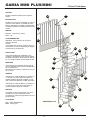
PRODOTTO
Scala a giorno adatta a piccoli ambienti.
19
18
DESCRIZIONE
Scala con struttura modulare in acciaio e
gradini a passo alternato in multistrato di faggio.
Ringhiera a colonne in metallo a sbalzo, oppure
a colonne in metallo e corrimano in legno.
PEDATE
20
19
Gradini: rampe 24.0 (12.0x2)
Pianerottolo: 90°
16
ALZATE
Regolabili: da min. 20.0 a max 24.0
Sbarco:
- Sotto Soletta con gradino di sbarco posto
ad una lazata inferiore rispetto la quota del
pavimento di sbarco.
17
STRUTTURA
15
12
Composta da elementi metallici, "supporti",
assemblati tra loro tramite bullonatura.
La struttura del pianerottolo, composta da un
elemento a "T", permette la rotazione del senso
di salita.
10
8
GRADINI
14
I gradini sono sagomati per creare la pedata
alternata e sono prodotti in multistrato di faggio
di spessore 4.0.
Il fissaggio alla struttura avviene tramite viti
da legno.
13
9
RINGHIERA
- A colonne in metallo Ø25 mm, fissate ai
gradini tramite dei giunti di materiale plastico
"nottolini" e al corrimano tramite le apposite
"CIME".
- A colonne in metallo Ø25 mm, sagomate a
"L" fissate ai gradini tramite dei giunti di
materiale plastico "nottolini".
6
11
7
FINITURA
4
Le parti in legno sono verniciate con due strati
di vernice trasparente all'acqua.
Le parti in metallo sono verniciate a forno con
polveri epossidiche.
5
COLORI
3
Legno: Tinta NATURALE
Metallo: Grigio argento
MINI PLUS
2
1
Rintal S.p.a
26
Revisione 1 - 16/05/05
GAMIA MINI PLUS/MINI
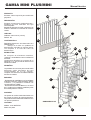
Prècis Technique
Caractéristiques techniques
PRODUIT
Escalier modulaire indiqué pour espaces
réduits.
19
18
DESCRIPTION
Escalier avec structure modulaire en acier et
marches à pas alterné en stratifié de hêtre.
Rampe à balustres en métal à encorbellement,
ou rampe à balustres en métal et main courante
en bois.
20
19
GIRONS
16
Marches : volée 24.0 (12.0x2)
Palier : 90°
CONTREMARCHES
Réglables : dun minimum de 20.0 à un
maximum de 24.0
Arrivée :
- Sous-dalle avec marche darrivée située à
une hauteur de marche inférieure par rapport
à la hauteur du sol darrivée.
17
15
12
10
STRUCTURE
8
Composée déléments métalliques, des
"supports"; assemblés entre eux par la visserie.
La structure du palier, composée dun élément
en "T", permet la rotation du sens de la montée.
14
MARCHES
13
Les marches sont profilées afin de créer la
marche alternée et elles sont en stratifié hêtre
de 4.0 dépaisseur.
La fixation à la structure seffectue au moyen
de vis à bois.
9
RAMPES
6
- Balustres en métal de Ø25 mm, profilés en
"L" et fixés aux marches par des joints en
matière plastique appelés "nottolini" et à la
main courante à laide des "CIME" spéciales.
11
7
- Balustres en métal de Ø25 mm, profilés en
"L" et fixés aux marches par des joints en
matière plastique appelés "nottolini".
4
5
FINITION
Les parties en bois sont peintes avec deux
couches de vernis transparent à leau.
Les parties en métal sont peintes au four à la
peinture époxy.
3
COULEURS
Bois : Teinte NATURELLE
Métal : Gris argent
GAMIA MINI PLUS
2
1
Rintal S.p.a
27
Revisione 1 - 16/05/05
GAMIA MINI PLUS/MINI
Manual técnico
Características técnicas
PRODUCTO
19
18
Escalera clásica especial para ambientes
pequeños.
DESCRIPCIÓN
Escalera con estructura modular de acero y
peldaños de paso alternado de haya
contrachapada
Baranda de barrotes de metal y pasamano de
madera o baranda con barrotes de metal de
resalte.
20
19
16
HUELLAS
Peldaños: tramos 24.0 (12.0x2)
Rellano: 90°
CONTRAHUELLA
17
Regulables: desde mín. 20.0 hasta máx. 24.0
Desembarque:
Debajo de la losa con peldaño de
desembarque colocado en posición inferior
con respecto a la cota del suelo de
desembarque.
15
12
10
ESTRUCTURA
8
Se compone de elementos metálicos,
"soportes", ensamblados entre sí mediante la
tornillerìa.
La estructura del rellano se compone de un
elemento en "T" que permite la rotación en el
sentido de subida.
14
13
PELDAÑOS
9
Los peldaños son en forma para crear la huella
alternada, están fabricados de haya
contrachapada de 4,0 de espesor.
La fijación a la estructura se realiza mediante
tornillos de madera.
6
BARANDA
11
7
- De barrotes de metal Ø25 mm, a los peldaños
mediante juntas de material plástico fijados
"nottolini" y al pasamano mediante las
correspondientes "CIME".
- De barrotes de metal de Ø25 mm, en forma
de "L" fijados a los peldaños mediante juntas
de material plástico "nottolini".
4
5
ACABADO
Las partes de madera están barnizadas con
dos capas de pintura al agua transparente.
Las partes de metal están barnizadas al horno
con polvos epoxídicos.
COLORES
3
GAMIA MINI PLUS
2
Madera: Color NATURAL
Metal: Gris plata
1
Rintal S.p.a
28
Revisione 1 - 16/05/05
GAMIA MINI PLUS/MINI
Technical Handbook
Technical characteristics
PRODUCT
19
18
Open staircase suitable for small spaces.
DESCRIPTION
Stair with a modular structure in steel and
alternating steps in plywood beech.
Railing with metal balusters and a wooden
handrail, or L shaped metal baluster railing.
TREADS
20
19
Steps: flight 24.0 (12.0x2)
Landing: 90°
16
RISERS
Adjustable: from min. 20.0 to max 24.0
Landing:
- Under floor level, with the landing step placed
one rise below the level of the landing floor.
17
STRUCTURE
15
12
Composed of metal elements, "supports",
assembled together by means of bolts and
nuts.
The structure of the landing, composed of an
"T" shaped element, consents the rotation of
the sense of climbing.
10
8
14
STEPS
The steps are shaped to create an alternating
tread and are produced in 4.0cm beech multiply. These are fixed to the structure by means
of wooden screws.
13
9
RAILING
- With Ø25mm metal balusters, fixed to the
steps with plastic nottolino joints and attached
to the handrail with the appropriate "CIME".
6
- With Ø25 mm "L" shaped metal balusters,
fixed to the steps with plastic nottolino" joints.
11
7
FINISH
The wooden parts are varnished with two
layers of transparent water-based varnish.
The metal parts are painted with oven-dried
epoxy paint.
4
5
COLOURS
Wood: NATURAL colour
Metal: Silver-grey
3
GAMIA MINI PLUS
2
1
Rintal S.p.a
29
Revisione 1 - 16/05/05
GAMIA MINI PLUS/MINI
Technische Beschreibung
Technische Eigenschaften
PRODUKT
19
18
Offene Treppe, geeignet für kleine Räume.
BESCHREIBUNG
Treppe mit modularer Struktur aus Stahl und
mit abwechselnd ausgerichteten Stufen aus
Buchen-Multiplex.
Geländer mit Geländerstäben aus Metall und
Handlauf aus Holz, oder mit L-förmigen
Geländerstäben aus Metall.
20
19
TRITTSTUFEN
16
Stufen: Rampen 24,0 (12,0x2)
Podest: 90°
STEIGUNGEN
Einstellbar: von min. 20,0 bis max. 24,0
Austritt:
- Unterhalb Oberkante Fertigßboden der
Decke mit Austrittsstufe eine Setzstufe
unterhalb der Höhe des Deckenbodenaustritts.
17
15
12
AUFBAU
10
Besteht aus Metallelementen, Stützen, die
untereinander mit Schraubenbolzen befestigt
sind.
Die Struktur des Podestes besteht aus einem
"T"-förmigen Element und ermöglicht eine
Drehung der Steigrichtung.
8
14
13
STUFEN
Die Stufen sind so geformt, dass abwechselnd
ausgerichtete Trittstufen entstehen und
bestehen aus 4,0 Dicke Buchen-Multiplex.
Sie werden mit Holzschrauben an der Struktur
befestigt.
9
GELÄNDER
6
- Aus Metall-Geländerstäben von Ø25 mm,
die an den Stufen mit KunststoffAnschlusselementen (Nottolini) am Handlauf
mit den dafür vorgesehenen CIME (oberen
Anschlussstücken) befestigt sind.
11
7
- Aus L-förmigen Metall-Geländerstäben von
Ø25 mm, die mit KunststoffAnschlusselementen (Nottolini) an den Stufen
befestigt sind.
4
5
OBERFLÄCHENAUSFÜHRUNG
Die Bestandteile aus Holz sind mit zwei
Schichten wasserlöslicher Beize eingelassen.
Die Bestandteile aus Metall wurden mit
ofentrocknendem Pulverlack auf
Epoxidharzgrundlage lackiert.
3
GAMIA MINI PLUS
FARBEN
2
Holz: Farbton NATUR
Metall: Silbergrau
Rintal S.p.a
1
30
Revisione 1 - 16/05/05
GAMIA MINI PLUS/MINI
Prontuario tecnico - Prècis Technique Manual Tècnico Technical Handbook Technische Beschreibung
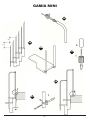
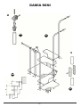
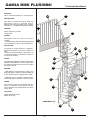
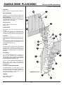
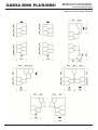
Nomenclatura componenti
1 50/4660 - BICCHIERE D.25 DUP
4
2 60/6500 - SUPP. PARTENZA MINI
3 60/6510 - SUPP. INTERMEDIO MINI
4 60/2690 - COLONNA VUOTA D. 25 L. 1165
16
5 64/695 - RACCORDO NOTTO D. 25
6 60/6520 - SUPP. PIANEROTTOLO MINI
17
7 60/4090 - TAPPO D. 50
8 50/4070 - RACCORDO CORRIMANO FE
15
9 61/5350 - CORRIMANO KNOCK
10 64/645-6-7-8 - CIMA "A" - "B" - "C" - "D"
11 52/N1201005 - PIANEROTTOLO MINI
12
12 52/N1201000 - GRADINO MINI
13 60/4076 - RACCORDO COLONNA MINI
14 60/4080 - ANELLO COLONNA FE
15 50/2650 - COLONNA VUOTA D. 25 L. 964 DUP
16 50/6530 - PIASTRA SBARCO MINI
11
5
17 64/651 - BASE "B"
18 50/2650 - COLONNA VUOTA D. 25 L. 925 DUP
19 50/4674 - COLONNA FERMOBLOCK D. 25
6
20 50/4668 - BICCHIERE ORIZZ. D. 25
3
5
3
GAMIA MINI
2
1
Rintal S.p.a
31
Revisione 1 - 16/05/05
GAMIA MINI PLUS/MINI
Prontuario tecnico - Prècis Technique Manual Tècnico Technical Handbook Technische Beschreibung
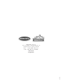
Confezionamento - Conditionnement - Embalaje - Packaging - Verpackung
KIT BALAUSTRA LEGNO
MINI MT. 1 DUPONT/NAT.12
KIT BASE MINI
Cod. K9/08GR12
Cod. K3/01GR12
KIT RINGHIERA FERRO
MINI DUPONT 11 GRADINI
KIT RINGHIERA LEGNO
MINI 3 GRADINI DUPONT/NAT. 12
Cod. K9/01GR00
Cod. K9/09GR12
KIT IRRIGIDIM
COL/COLONNA D.25
IR3 - DUPONT
KIT GRA+RINGH FERRO
MINI DUPONT
Cod. K9/10GR12
Cod. K9/02GR00
KIT RINGH FERRO MINI
LATO PIANEROTTOLO DUPONT
KIT IRRIGIDIM
COL/PARETE D.25 IR3
DUPONT
Cod. K9/03GR00
Cod. K9/11GR00
KIT COLONNA STOP D. 25
IR3 - DUPONT
KIT RINGH LEGNO MINI
11 GRAD. - DUPONT/NAT. 12
Cod. K9/12GR00
Cod. K9/04GR12
KIT GRAD+RINGH LEGNO
MINI DUPONT/NAT. 12
KIT RACCORD CORR
FE MINI
Cod. K9/05GR12
Cod. K9/14GR00
KIT PIANEROTTOLO MINI
DUPONT/NAT. 12
Cod. K9/06GR12
KIT RINGH LEGNO MINI LATO
PIANEROTTOLO - DUPONT/NAT.12
Cod. K9/07GR12
Rintal S.p.a
32
Revisione 1 - 16/05/05
Prontuario tecnico - Prècis Technique Manual Tècnico Technical Handbook Technische Beschreibung
GAMIA MINI PLUS/MINI
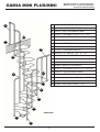
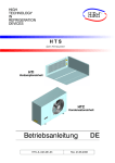
Dimensioni generali - Dimensions générales Dimensiones generales - General dimensions - Allgemeine Abmessungen
150.0
70.0
S
12.0
HT
37.1
20.0÷24.0
21.0
4.6
55.0
Conformazioni tipo - Configurations - Configuraciones - Configurations - Treppenverläufe
Rintal S.p.a
33
Revisione 1 - 16/05/05
GAMIA MINI PLUS/MINI
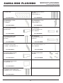
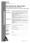
Prontuario tecnico - Prècis Technique Manual Tècnico Technical Handbook Technische Beschreibung
Dimensionamento rampe - Dimensionnement des volées - Dimensionamiento de rampas
Flight size - Bemessung der Rampen
Rintal S.p.a
34
Revisione 1 - 16/05/05
V1 05/05
R I N TA L S . p . a .
Via Traiano Imperatore, 6
4 7 1 0 0 F o r l ì ( F C ) I TA LY
Te l . + 3 9 . 0 5 4 3 . 7 9 1 1 1 1
Fax +39.0543.722544
www.rintal.it
[email protected]