1
2701525-ES-rev.D
TECHNICAL MANUAL
(INSTALLATION, OPERATOR’S, AND PARTS)
MANUAL TÉCNICO
(INSTALACIÓN, FUNCIONAMIENTO Y PIEZAS)
JACOBSEN CORE HARVESTER
ACCESSORY PART NO. 4119652
NÚMERO DE PIEZA DEL ACCESORIO 4119652
WARNING
WARNING: If incorrectly used this machine can cause severe
injury. Those who use and maintain this machine should be
trained in its proper use, warned of its dangers and should
read the entire manual before attempting to set up, operate,
adjust or service the machine.
ADVERTENCIA
ADVERTENCIA: Si se usa de forma incorrecta, esta máquina
puede causar graves lesiones. Las personas que usen y
mantengan esta máquina deben conocer su uso correcto, ser
conscientes de sus peligros y leer todo el manual antes de
tratar de instalar, manejar, ajustar o revisar la máquina.
When Performance Matters.™
GB
ES
United
Kingdom
Spain
RJL 100 April 2010
GENERAL INFORMATION
Additional manuals are available through your dealer.
IMPORTANT!
IMPORTANT!
THIS MANUAL WILL AID YOU IN THE SAFE
OPERATION AND PROPER MAINTENANCE OF
YOUR EQUIPMENT. READ MANUAL THOROUGHLY
BEFORE ATTEMPTING OPERATION. IF ANY
PORTION IS NOT CLEARLY UNDERSTOOD,
CONTACT AN AUTHORIZED DEALER FOR
CLARIFICATION.
To make sure you are fully aware of safety and service
information, the following two symbols are used
throughout this manual.
!
This symbol is used throughout the manual to
alert you to information about unsafe actions or
situations, and will be followed by the word DANGER,
WARNING, or CAUTION. DANGER indicates
immediate hazards that may result in severe injury or
death. WARNING indicates unsafe actions or
situations that may cause severe injury, death and/or
major equipment or property damage. CAUTION
indicates unsafe actions or situations that may cause
injury, and/or minor equipment or property damage.
NOTE: This appears next to information or instructions
which will help you operate and maintain your
equipment the right way.
THIS EQUIPMENT SHOULD NOT BE MODIFIED OR
ADDED TO WITHOUT THE MANUFACTURER’S
AUTHORIZATION.
!
WARNING
• Altering this equipment in any manner which
adversely affects the equipments operation,
performance, durability or use, may cause
hazardous conditions.
Direct any inquiries to:
Jacobsen, a Textron Company
Attn: Engineering
11524 Wilmar Blvd
Charlotte, NC 28273 USA
SPECIFICATION INFORMATION
All information contained in this manual is the latest
available at the time of printing. Textron Turf Care and
Specialty Products reserves the right to make changes
at any time without notice.
Whenever a name brand product is specified, an
equivalent product may be used unless stated
otherwise.
CHANGE OF OWNERSHIP OR ADDRESS
!
WARNING
• The information and instructions included in
this manual alert you to certain things you
should do very carefully. If you do not, you
could:
• hurt yourself or others
• hurt the next person who operates the
•
equipment
damage the equipment.
Textron Turf Care and Specialty Products makes every
effort to keep owners informed of all safety related
information. Therefore, changes in ownership and/or
address should be reported to the manufacturer.
Your dealer has REGISTRATION CHANGE FORMS
which will be filled out and filed by the dealer for his
records, and a copy will be sent to the manufacturer.
2006/42/EC These are the Original instructions verified
byJacobsen a Textron company.
• This manual contains essential operation and
safety information and must remain with the
unit at all times, within easy access of any
operator.
Litho in U.S.A. 7–2006
©2000 TEXTRON INC. • All Rights Reserved.
CHarlotte, North Carolina
TABLE OF CONTENTS
Section
Page No.
1—— Models Used On . . . . . . . . . . . . . . . . . . . . . . . . . . . . . . . . . . . . . . . . . 2
2—— Identification . . . . . . . . . . . . . . . . . . . . . . . . . . . . . . . . . . . . . . . . . . . . 2
3—— Service Parts and Material . . . . . . . . . . . . . . . . . . . . . . . . . . . . . . . . . 2
4—— Set-Up . . . . . . . . . . . . . . . . . . . . . . . . . . . . . . . . . . . . . . . . . . . . . . . . . 3
4.1—— Unpacking . . . . . . . . . . . . . . . . . . . . . . . . . . . . . . . . . . . . . . . . . . . . . 3
4.2—— Tailgate Release Installation . . . . . . . . . . . . . . . . . . . . . . . . . . . . . . . 3
4.3—— Installing Elevator Assembly
For Trucksters July, 1998 and Prior . . . . . . . . . . . . . . . . . . . . . . . . . . 4
4.4—— Installing elevator assembly
For Trucksters August, 1998 and Newer . . . . . . . . . . . . . . . . . . . . . . 4
4.5—— Install Pipe Nipples . . . . . . . . . . . . . . . . . . . . . . . . . . . . . . . . . . . . . . 7
4.6—— Install Caster (Yoke) Assembly . . . . . . . . . . . . . . . . . . . . . . . . . . . . . 8
4.7—— Install Air Shock Absorber . . . . . . . . . . . . . . . . . . . . . . . . . . . . . . . . . 8
4.8—— Install Lower Link and Upper Tension Springs . . . . . . . . . . . . . . . . . . 9
4.9—— Install Lift Handle . . . . . . . . . . . . . . . . . . . . . . . . . . . . . . . . . . . . . . . 10
4.10—— Conveyor Mounting . . . . . . . . . . . . . . . . . . . . . . . . . . . . . . . . . . . . . 11
4.11—— Routing Hydraulic Hoses . . . . . . . . . . . . . . . . . . . . . . . . . . . . . . . . . 13
4.12—— Shoe Assembly . . . . . . . . . . . . . . . . . . . . . . . . . . . . . . . . . . . . . . . . 14
4.13—— Core Windrow Installation . . . . . . . . . . . . . . . . . . . . . . . . . . . . . . . . 15
5—— Hydraulic System . . . . . . . . . . . . . . . . . . . . . . . . . . . . . . . . . . . . . . . 16
6—— Adjustments . . . . . . . . . . . . . . . . . . . . . . . . . . . . . . . . . . . . . . . . . . . 16
6.1——
6.2——
6.3——
6.4——
Leveling Vehicle. . . . . . . . . . . . . . . . . . . . . . . . . . . . . . . . . . . . . . . .
Extension Boards. . . . . . . . . . . . . . . . . . . . . . . . . . . . . . . . . . . . . . .
Adjusting Conveyor Belt . . . . . . . . . . . . . . . . . . . . . . . . . . . . . . . . .
Tension Spring Adjustment . . . . . . . . . . . . . . . . . . . . . . . . . . . . . . .
16
16
16
17
7—— Operation. . . . . . . . . . . . . . . . . . . . . . . . . . . . . . . . . . . . . . . . . . . . . . 17
8—— Maintenance . . . . . . . . . . . . . . . . . . . . . . . . . . . . . . . . . . . . . . . . . . . 18
8.1——
8.2——
8.3——
8.4——
Hydraulic Reservoir Oil . . . . . . . . . . . . . . . . . . . . . . . . . . . . . . . . . .
Lubrication . . . . . . . . . . . . . . . . . . . . . . . . . . . . . . . . . . . . . . . . . . . .
Elevator Chain Adjustment . . . . . . . . . . . . . . . . . . . . . . . . . . . . . . .
Adjusting Conveyor Belt . . . . . . . . . . . . . . . . . . . . . . . . . . . . . . . . .
18
18
18
18
9—— Disconnecting Core Harvester . . . . . . . . . . . . . . . . . . . . . . . . . . . . 19
10—— Declaration of Incoporation . . . . . . . . . . . . . . . . . . . . . . . . . . . . . . . . 20
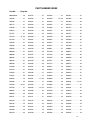
11—— Torque Chart . . . . . . . . . . . . . . . . . . . . . . . . . . . . . . . . . . . . . . . . . . . 22
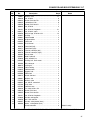
12—— Parts Section . . . . . . . . . . . . . . . . . . . . . . . . . . . . . . . . . . . . . . . . . . . 24
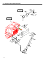
12.1—— Elevator Panels and Boot . . . . . . . . . . . . . . . . . . . . . . . . . . . . . . . .
12.2—— Chain, paddles, and Sprockets . . . . . . . . . . . . . . . . . . . . . . . . . . . .
12.3—— Hydraulic System. . . . . . . . . . . . . . . . . . . . . . . . . . . . . . . . . . . . . . .
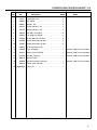
12.4—— Elevator and Conveyor Mount . . . . . . . . . . . . . . . . . . . . . . . . . . . . .
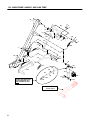
12.5—— Main Frame, Handle, and Link Tube . . . . . . . . . . . . . . . . . . . . . . . .
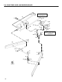
12.6—— Push Tube, Shoe, and Windrow Blade . . . . . . . . . . . . . . . . . . . . . .
12.7—— Conveyor and Box Extensions. . . . . . . . . . . . . . . . . . . . . . . . . . . . .
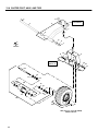
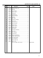
12.8—— Caster Pivot, axle, and Tire . . . . . . . . . . . . . . . . . . . . . . . . . . . . . . .
24
26
28
30
32
34
36
38
1
1 MODELS USED ON
1
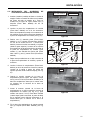
MODELS USED ON______________
The Core Harvester accessory, Part No. 4119652, can
be used on Turf Truckster Models 84043, 84044,
84056, 84057, 84061, 898530, 898532, 898543,
898627, 898628, 898630, 898632, 898633, 898634,
898636, 898637, 898650, 898652, 898659, 898662,
898663, 898664, 898684, 898685, 898656, 898657, &
898658. Refer below to see if the Turf Truckster
requires a conversion kit.
2
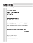
IDENTIFICATION ________________
The part number and serial number of the accessory
are printed on the name plate decal located on the
main frame (See Fig. 1).
The part number and serial number MUST appear on
all correspondence concerning this accessory.
NAME PLATE
DECAL
Installation on small rear tire Cushman Turf Truckster
models 898530, 898532, 898543, 898630, & 898632.
DO NOT install the Core Harvester on any of the small
tire models that are equipped with a cab or a ROPs
(Part No. 892689).
Conversion Kits:
• 891252 Yoke Kit . . . . . . . . . . . . . . . . . . . . Required
• 887933 Auxiliary Transmission Gear Set
. . . . . . . . . . . . . . . . Required for units 8610 and prior
• 888453 Hydraulic Update Kit . . . Required for units
8910 and prior
• 889558 Remote Coupler Kit . . . . Required for units
9010 and prior
Installation on older large rear tire (23 x 13-10) Turf
Truckster models 898530, 898532, 898630, 898632,
898633, 898634, 898636, & 898637. DO NOT install
the Core Harvester on any of the large tire models that
are equipped with a cab or a ROPs (Part No. 892689).
•
No Conversion Kits Required.
Installation on newer Turf Trucksters with large tires
(23 x 13-10) models 898650, 898652, 898659,
898662, 898663, 898664, 898684, 898685, 898656,
898657, & 898658. The Core Harvester CAN BE
installed on any of these models that are equipped with
an upper ROPs (Part No. 894761).
•
No Conversion Kits Required.
2
Figure 1
3
SERVICE PARTS AND MATERIAL _
Description ............................................ Part Number
Paddle, elevator chain ...................................... 832334
Coupler, chain ................................................... 832421
Link, chain......................................................... 832422
Link, attachment................................................ 832423
Turf Protector™ hydraulic oil
2.5 gal. (9.7 L) ..................................................... 65363
5 gal. (18.9 L) ...................................................... 65352
55 gal. (208 L) ..................................................... 65354
SET-UP 1
1
1.1
SET-UP _______________________
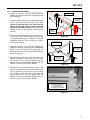
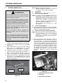
UNPACKING __________________________
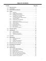
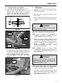
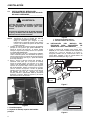
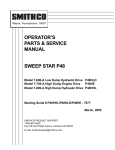
1. Remove the banding strap used to secure the
elevator and loose parts to the pallet. Remove all
loose parts and boxes, except the elevator
assembly, from the shipping pallet. Remove any
banding straps securing the push tube assembly to
the elevator (See Fig. 2).
!
CAUTION
Keep hands and fingers away from pinch points.
Since these parts pivot, it is possible to injure
the hands and/or fingers when raising or rolling
the elevator assembly.
2. Pivot the push tube assembly to the front of the
elevator and allow push tube to rest on floor. Roll
the elevator 180_ so the shock and main pivot
shaft are on the bottom (the shock, main frame
and main pivot shaft will pivot unless they are
secured to the elevator, you may want to attach
banding or straps to these items so they do not
pivot as the elevator is being rolled or raised) (See
Fig. 3).
NOTE: Any reference to the front, back, left or right
side of the vehicle will always be determined
from the operator’s seated position.
3. Remove vehicle left side panel.
4. Remove left hip restraint on Trucksters July, 1998
and prior.
IMPORTANT!
IF YOUR VEHICLE IS EQUIPPED WITH A SHORT
BOX SET AND TAILGATE RELEASE SET, PART NO.
885488, THIS TAILGATE RELEASE MUST BE
REMOVED. IT WILL BE MOVED TO THE RIGHT
SIDE OF SHORT BOX. NOTE POSITION AND
RETAIN ALL PARTS WHEN REMOVING.
1.2
TAILGATE RELEASE INSTALLATION
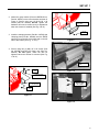
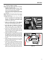
1. Mark the location as shown, lower portion of right
box side panel (See Fig. 4). Drill one 11/32”
(9 mm) diameter hole through box. The bracket
will be in same location as bracket on left side.
Secure with 5/16-18 x 5/8 screw (Part No. 306555)
and flangelock nut (Part No. 548911).
REF. BRACKET 823038
4"(102 mm)
3 3/16"(81 mm)
LIFT & PIVOT THE PUSH
TUBE AND LET IT REST
ON THE FLOOR
REF. BOTTOM OF BOX
PUSH TUBE
Figure 2
SHOWN FOR
REFERENCE ONLY
ROLL THE
ELEVATOR 180_
THE ELEVATOR IS SHIPPED
UPSIDE DOWN, ROLL THE
ELEVATOR TO PROPERLY
INSTALL ON VEHICLE
REF. FRONT
BOX POST
RIGHT SIDE
Figure 4
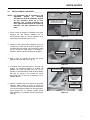
2. Insert plate assembly inside the right front box
post. Secure with existing hardware. Drill holes if
required.
3. Attach handle/pivot holder to existing top holes in
post using existing hardware.
4. Remove the existing tailgate release at right rear of
short box. Install new tailgate release latch (Part
No. 830950). Use existing hardware.
5. Insert the tailgate release rod through bracket on
box. Install bushing, washer, spring and washer
on rod and insert through box post and handle
pivot.
6. Assemble tailgate rod to new latch with flatwasher
and new cotter pin (Part No. 306328).
7. Push front flatwasher back against spring and
insert new cotter pin (Part No. 306328) through
rod.
Figure 3
3
1 SET-UP
1.3
INSTALLING ELEVATOR ASSEMBLY FOR
TRUCKSTERS JULY, 1998 AND PRIOR ____
!
WARNING
The elevator assembly is heavy and requires two
or more people to lift it. Use proper lifting
techniques to avoid injury.
1
2
If a hoist is used to lift the unit, keep feet and
legs out from underneath the elevator while it is
being raised.
NOTE: Make sure the push tube assembly is
positioned forward.
Loosen hardware securing hydraulic box on
stopwall to gain access to main frame mounting
hardware.
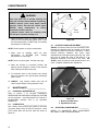
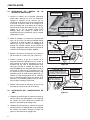
1. Place the main frame upper mounting bracket in
position against the FRONT of vehicle stopwall. At
the same time place lower mounting bracket in
position on vehicle FRAME RAIL.
Use two screws, 5/16-18 x 1 (Part No. 306416),
four flat washers, two lockwashers and nuts to
secure upper mounting bracket to stopwall (See
Fig. 5). Tighten hydraulic box hardware.
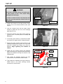
2. Raise and support lower end of elevator enough so
lower mounting bracket can be clamped in place
against vehicle frame rail; with bracket top flange
down against top of frame rail. Clamp in place.
Use holes in bracket as a template. Drill four (4)
13/32” (10 mm) holes through frame rail (See Fig.
6). Secure with four screws, 3/8-16 x 1 (Part No.
306414), lockwashers and nuts. Remove clamps
and support at lower end of elevator.
4134
Figure 6
1. Lower Mounting Bracket
2. Vehicle Frame Rail
1.4
INSTALLING ELEVATOR ASSEMBLY _____
FOR TRUCKSTERS AUGUST, 1998 AND NEWER
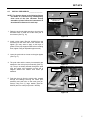
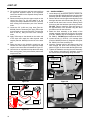
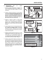
1. Install the black Mount Bracket (Part No. 894698)
to the existing holes in the vehicle frame as shown
in Figure 1. Secure using two (2) M10-1.50 x 30
screws (Part No. 452400) and two (2) M10-1.50
nuts (Part No. 450454) (See Fig. 7 & 8).
PART NO.
450454
MOUNTING BRACKET
PART NO. 894698
PART NO.
452400
Figure 7
1
2
4133
MOUNT BRACKET
Figure 5
1. Stopwall
2. Main Frame Upper Mounting Bracket
4
Figure 8
SET-UP 1
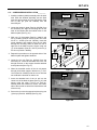
2. Attach the green bracket (Frame-to-ROPS Mount,
Part No. 844797) to the mount bracket as shown in
Figure 3. Secure using two (2) M10-1.50 x 30
screws (Part No. 452400). Do Not tighten, the
hardware will need to remain loose for adjustment
when the elevator is installed (See Fig. 9 & 10).
FRAME-TO-ROPS MOUNT
PART NO. 844797
PART NO.
452400
3. Install the clamping bracket (Part No. 844798) and
clamping plate (Part No. 844668) onto the ROPS
structure just to the left of the hand hold on the left
side of the vehicle (See Fig. 11 & 12).
Figure 9
4. Secure using two (2) M8-1.25 x 25 screws (Part
No. 452389) and M8-1.25 flange nuts (Part No.
450453). Do Not tighten, these will also be
tightened when the elevator is mounted (See Fig.
11 & 12).
FRAME-TO-ROPS
MOUNT
PART NO.
450453
Figure 10
CLAMPING BRACKET
PART NO. 844798
THE ELEVATOR WILL
MOUNT TO THESE
TWO (2) HOLES
CLAMPING PLATE
PART NO. 844668
PART NO.
452389
Figure 11
Figure 12
5
1 SET-UP
!
WARNING
The elevator assembly is heavy and requires two
or more people to lift it. Use proper lifting
techniques to avoid injury.
If a hoist is used to lift the unit, keep feet and
legs out from underneath the elevator while it is
being raised.
FRAME-TO-ROPS
MOUNT
LOWER ELEVATOR
MOUNT BRACKET
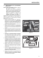
5. Position the elevator so the lower elevator mount
bracket sets on the frame-to-ROPS mount (See
Fig 13).
Figure 13
6. Lean the elevator back until the upper mount
bracket is against the the front of the clamping
plate (See Fig. 14).
7. Secure the elevator to the lower mount using four
(4) M10-1.50 x 70 screws (Part No. 452404). Do
Not tighten.
8. If necessary, place blocks (or equivalent) beneath
the elevator for support while it is being mounted.
9. Secure the upper elevator mount bracket to the
clamping plate using two (2) M8-1.25 x 25 screws
(Part No. 452389) and flange nuts (Part No.
450453). Begin tightening the hardware as
follows:
10. Tighten the two screws securing the clamping
plate and bracket to the top part of the ROPS then,
tighten the hardware securing the elevator to the
clamping plate.
11. Next, tighten the hardware securing the lower
elevator mount to the frame-to-ROPS mount.
Figure 14
PART NO.
452404
CLAMPING PLATE
AND BRACKET
PART NO.
452389
FRAME-TOROPS MOUNT
CORE HARVESTER
MAIN FRAME IS SHOWN
WITHOUT ELEVATOR FOR
REFERENCE ONLY
12. Then, tighten the hardware securing the frame-toROPS mount to the black mounting bracket
secured to the vehicle frame.
PART NO.
452404
Figure 15
6
SET-UP 4
4.5
INSTALL PIPE NIPPLES ________________
PUSH TUBE
NOTE: The photo’s shown in the following figures
are shown as a reference only, although they
show areas of the Core Harvester already
assembled, please follow the instructions as
described and referenced in each step.
NEED TO KEEP PUSH TUBE
HIGH ENOUGH TO CLEAR
THREADED HOLES
PIPE
NIPPLE
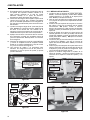
1. Raise the push tube high enough to clear the two
threaded holes on each side of the lower part of
the elevator (See Fig. 16).
Figure 16
2. Install a pipe nipple (Part No. 832430) from the
accessory kit onto each side of the elevator and
tighten (you may want to apply a thin layer of
grease on the pipe nipple threads before installing
them, tighten using an adjustable pipe wrench).
PIPE
NIPPLE
PUSH
TUBE
3. Lower the push tube so it rests on the pipe nipples
(See Fig. 17).
4. The push tube and the caster pivot assembly are
attached to the main pivot pin assembly (See Fig.
18). The pin is already inserted through the push
tube and caster pivot assembly mounts but is
shipped without the washer and cotter pin
attached.
Figure 17
CASTER PIVOT
ASSEMBLY
SECURE END
OF PIVOT PIN
WITH WASHER
AND COTTER PIN
5. Push the pivot pin from the vehicle side, outward
through all bushings securing the caster pivot
assembly and push tube to the main pivot pin.
Secure using one (1) large washer (Part No.
832479) and one cotter pin (Part No. 325109).
MAIN
PIVOT PIN
Figure 18
7
4 SET-UP
4.5
INSTALL CASTER (YOKE) ASSEMBLY ____
1. Locate the caster (yoke) assembly (Part No.
890118) from the accessory kit. Face the opening
of the slots at the bottom of the yoke towards the
front of the vehicle and insert the yoke stem into
the mounting tube at the end of the caster pivot
assembly (See Fig. 19). Secure using one (1) lock
ring (Part No. 548349). Carefully lower the caster
and yoke assembly allowing the yoke to rest on the
floor.
CASTER PIVOT
ASSEMBLY
CASTER YOKE
ASSEMBLY
INSERT YOKE STEM
THROUGH CASTER
PIVOT TUBE
2. Mount the tire and rim to the axle and hub
assembly. The axle and hub will be installed from
the side of the rim opposite the valve stem (See
Fig. 20). Insert the wheel mounting studs through
the mounting holes and secure using four (4)
wheel retaining nuts (Part No. 805860).
Figure 19
HUB AND AXLE
ASSEMBLY
3. Torque the wheel retaining nuts to 70-100 ft. lbs.
(95 to 140 N×m).
4. Install the wheel and axle onto the caster yoke
assembly sliding the axle against the rear side of
the slot. Make sure the hardware on the axle is
loose enough to allow the yoke frame to be
mounted between the two large washers on each
side of the yoke (See Fig. 21) or remove the nut,
lockwasher and one large washer from each end
of the axle, slide the wheel on making sure to keep
one (1) large washer on the inside of the yoke
frame, and one large washer on the outside of the
yoke frame. Replace the hardware.
5. Torque the axle retaining nuts to 70-100 ft. lbs.
(95 to 140 N×m).
4.5
INSTALL ON SIDE
OF RIM OPPOSITE
THE VALVE STEM
FRONT OF
VEHICLE
VALVE STEM
Figure 20
CASTER YOKE
ASSEMBLY
MAKE SURE THERE IS A LARGE
WASHER ON THE INSIDE AND
OUTSIDE OF THE YOKE FRAME
ON THE OPPOSITE SIDE ALSO
LARGE WASHER
ON OUTSIDE OF
YOKE FRAME
LARGE WASHER
ON INSIDE OF
YOKE FRAME
INSTALL AIR SHOCK ABSORBER________
1. Using hardware provided, attach the lower end of
the shock absorber to the caster pivot assembly
stud (Refer to parts illustration on page 30).
2. Using hardware provided, attach the upper end of
the shock absorber to the main frame assembly
stud (Refer to parts illustration on page 30).
8
WHEEL
RETAINING NUT
SLIDE AXLE
AGAINST THE BACK
OF THE SLOT
Figure 21
SET-UP 4
4.5
INSTALL LOWER LINK AND UPPER
TENSION SPRINGS ____________________
1. Raise and support the lower end of the elevator.
Locate the 10 5/8” (270 mm) lower link spring
(Part No. 832525) from the accessory kit.
Connect one end of the spring to the bracket on
the lower link as shown in Figure 22 (the lower
link is located towards the lower front of the
elevator near the floorboard of the vehicle as
shown in Figure 23).
LOWER LINK SPRING
(10 5/8" (270 mm) LONG)
ADJUSTING
SCREW
NUT ON EACH SIDE OF
OVER-CENTER BRACKET
FRONT OF
VEHICLE
CONNECT TO BRACKET
ON LOWER LINK
LOWER LINK
Figure 24
LOWER LINK SPRING
[10 5/8" (270 mm) LONG]
UPPER
TENSION SPRING
FRONT OF
VEHICLE
SPRING MOUNT BAR
ON UPPER LINK
AS VIEWED FROM
THE PASSENGER SIDE OF VEHICLE
Figure 22
THE BRACKET ON THE
LOWER LINK IS LOCATED ON
THE SIDE OF THE ELEVATOR
FACING THE VEHICLE
THE LOWER LINK SPRING
IS SHOWN INSTALLED
TO REFERENCE IT'S LOCATION
Figure 23
2. Connect the other end of the spring to the
adjusting screw on the over-center bracket (See
Fig. 24).
3. Using the screw (Part No. 832438) and two (2) 3/816 nuts (Part No. 304632) from the Accessory Kit,
install them to the over-center bracket. Make sure
to keep one nut on each side of the bracket. The
spring will be adjusted later.
4. Connect one end of the 15 3/8” (391 mm) long
upper tension spring (Part No. 832322) to the
mount bar on the upper link (See Fig. 25).
Figure 25
5. Connect the other end of the spring to the adjusting
screw on the over-center bracket as shown in
Figure 26. Remove the screw (Part No. 832438)
and two (2) 3/8-16 nuts (Part No. 304632) from the
Accessory Kit and install them to the over-center
bracket. Make sure to keep one nut on each side of
the bracket. The spring will be adjusted later.
ADJUSTING
SCREW
UPPER TENSION SPRING
[15 3/8" (391 mm) LONG]
NUT ON EACH SIDE OF
OVER-CENTER BRACKET
FRONT OF
VEHICLE
Figure 26
9
4 SET-UP
4.5
INSTALL LIFT HANDLE _________________
1. The lift handle will mount to the shaft directly in
front of the over-center bracket (the over-center
bracket is the same bracket the two adjusting
screws and springs were previously attached to).
LIFT
HANDLE
ATTACH
SPRING
2. Locate the lift handle (Part No. 888271) and the
small handle spring (Part No. 812368) from the
Accessory Kit.
3. Apply a small amount of a lithium-based lubricant
to the lift handle mounting shaft and slide the
handle onto the shaft. The bracket welded on the
bottom of the handle will face towards the front of
the vehicle (See Fig. 27).
SLIDE HANDLE
ONTO SHAFT
OVER-CENTER
BRACKET
Figure 27
4. Secure the lift handle using one (1) retaining
washer (Part No. 548165) and one (1) cotter pin
(Part No. 304635).
LIFT
HANDLE
5. Attach one end of the handle spring to the
mounting tab at the bottom of the handle and
attach the other end of the spring to the hole on the
over-center bracket (See Fig. 27 & 28).
Figure 28
10
SET-UP 4
4.5
CONVEYOR MOUNTING ________________
1. Locate the conveyor, conveyor mount (Part No.
894845) and stake bracket (Part No. 888274) from
the accessory kit.
2. Place the stake bracket into the stake holder at the
rear of the left box-side (See Fig. 29). If your
vehicle is equipped with a box other than the
short box, the stake bracket will be installed
into the middle stake holder (the stake holder will
actually be closer to the rear than to the center of
the box).
3. Secure the stake bracket to the side-box using one
(1) 3/8-16 x 2 1/2” screw (Part No. 301431), one
(1) 3/8 flat washer (Part No. 306981), one (1) 3/8
lockwasher (Part No. 120177) and one (1) 3/8-16
nut (Part No. 306562).
STAKE BRACKET
LEFT REAR
STAKE HOLDER
(SHORT BOX)
STAKE
HOLDER
(LARGE BOX)
Figure 29
CONVEYOR MOUNT
PART NO. 894845
4. Install the conveyor mount (Part No. 894845), by
placing the short 90_ end-tube into the front stake
holder on the left side-box and positioning the
horizontal tube in the yoke on the stake bracket as
shown in Figure 30.
5. Secure the front side of the conveyor mount to the
side-box using one (1) 3/8-16 x 2 1/2” screw (Part
No. 301431), one (1) 3/8 flat washer (Part No.
306981), one (1) 3/8 lockwasher (Part No. 120177)
and one (1) 3/8-16 nut (Part No. 306562).
PLACE
END OF MOUNT
INTO YOKE
TO
FRONT, LEFT
STAKE HOLDER
Figure 30
6. Secure the rear side of the conveyor mount, to the
yoke on the stake bracket previously installed (See
Fig. 31). Insert one (1) 3/8-16 x 2 3/4” screw (Part
No. 307776) through the holes in the yoke and
secure using one (1) 3/8 flat washer (Part No.
306981), one (1) 3/8 lockwasher (Part No. 120177)
and one (1) 3/8-16 nut (Part No. 306562).
SHORT BOX SHOWN
INSTALLATION WILL BE THE SAME
ON THE LARGER BOX,
ONLY DIFFERENCE WILL BE THE
LOCATION OF THE STAKE HOLDER
Figure 31
11
4 SET-UP
7. Mount the conveyor onto the conveyor mount.
Position the conveyor onto the conveyor mount
plates using the illustration in Figure 32 as a
reference depending on which box your vehicle is
equipped.
LARGE BOX
8. Secure using four (4) M8-1.25 x 25 flange screws
(Part No. 452389) and four (4) M8-1.25 flange nuts
(Part No. 450453). Position the conveyor until the
screws are against the rear side of the slots and
tighten hardware.
SHORT BOX
9. It may be necessary to adjust the position of the
conveyor while using the Core Harvester for the
first time. The cores should drop from the elevator
onto the center of the conveyor belt. It is common
for some of the cores to hit off the sides of the
chute as well, but you do not want the cores to
over-shoot the conveyor. Adjust as necessary.
Figure 32
10. To adjust the conveyor, loosen the four (4)
conveyor-to-mount screws and slide the conveyor
to the desired location. Tighten the hardware once
the conveyor is properly positioned (See Fig. 33).
CONVEYOR
CONVEYOR MOUNT
Figure 33
12
SET-UP 4
4.11 ROUTING HYDRAULIC HOSES ___________
NOTE: Apply Teflon Pipe Thread Tape to all thread
joints on the hydraulic system.
Do Not over-tighten the hydraulic fittings. Tighten
joints until they do not leak, over-tightening the
joints can cause fitting damage and leaks.
Route hose so they clear parts that move and/or
get hot. Use wire ties to keep the hoses secured
in position.
Wipe all hydraulic fitting threads (male ends as well as
female ends) with a clean (lint free) cloth before
applying the Teflon tape.
1. Install the 90_ hydraulic fitting (Part No. 827395)
from the Accessory Kit, to the back of the
conveyor motor. Tighten the fitting so the hose
connector is facing down and slightly turned
towards the box (See Fig. 34).
2. Install the straight hydraulic fitting (Part No.
832396) from the Accessory Kit, to the bottom of
the conveyor motor and tighten (See Fig. 34).
90_ FITTING
PART NO. 827395
STRAIGHT FITTING
PART NO. 832396
NIPPLE
PART NO. 105706
3. Apply Teflon tape to the threads of the hydraulic
pipe nipple (Part No. 105706) from the Kit, and
install the pipe nipple to the straight fitting
previously connected to the bottom of the motor.
DRYSEAL COUPLER
PART NO. 894701
4. Locate one (1) dryseal female coupler (Part No.
894701) from the Kit. Install the coupler to the end
of the pipe nipple previously installed (make sure
Teflon tape is applied to the nipple).
5. Apply a couple turns of new Teflon tape to the hose
end and install one (1) hydraulic male coupler (Part
No. 894702) from the Kit. Route the hose to the
conveyor motor and connect the male coupler to
the female coupler on the bottom of motor (See
Fig. 35).
6. Apply Teflon tape to the threads of the 45_ fittings
(Part No. 521949) and install and secure fittings to
the elevator motor (See Fig. 35).
7. Locate the 30” (762 mm) long hydraulic hose from
the Kit , apply Teflon tape to one end of the hose
and install it to the 45_ fitting on the elevator motor.
8. Apply Teflon tape to the other end of the hose.
Locate one (1) dryseal female coupler (Part No.
894701) from the Kit and install it on the hose end.
Figure 34
CONVEYOR
MOTOR
ELEVATOR
MOTOR
45_
FITTING
FEMALE COUPLER
PART NO. 894701
MALE COUPLER
PART NO. 894702
Figure 35
13
4 SET-UP
9. The coupler will connect to the hose removed from
the upper-left hydraulic coupler on the hydraulic
control box located on the stopwall directly behind
the drivers seat.
10. Disconnect the hose from the upper coupler on the
control box (See Fig. 36) and attach it to the
coupler previously installed onto the 30” (762 mm)
hose coming from the bottom port of the elevator
motor.
11. Locate the 56” (1422 mm) long hose (Part No.
832398) from the Accessory Kit. Apply Teflon tape
to the threads on one end of the hose. Connect the
hose to the 90_ fitting on back of the conveyor
motor.
12. Apply Teflon tape to the threads on the other end
of the hose and install the other dryseal male
coupler (Part No. 894702) from the kit to the hose
end.
13. Route the hose to the hydraulic control box and
connect the male coupler to the upper-left female
coupler in the control box as illustrated in Figure 37.
14. Use wire ties or equivalent to keep the hoses away
from moving parts, pinch points and/or parts which
may become hot.
4.11 SHOE ASSEMBLY______________________
1. Locate the two (2) shoe braces (Part No. 832391, left
brace and Part No. 832392 right brace) and the shoe
assembly (Part No. 887963) from the Accessory Kit.
2. Remove the nut from the upper mounting hole on the
bearing at the lower left of the elevator (See Fig. 38).
3. Install the left shoe brace onto the bearing screw
and secure with the hardware previously removed.
DO NOT Tighten. Install the right shoe brace on
the opposite side of the elevator using the same
procedure used for the left brace.
4. Attach the shoe assembly to the bottom of the
elevator securing it with four (4) 5/8-18 x 5/8 screws
(Part No. 306555) and 5/8-18 flangelock nuts (Part
No. 548911). DO NOT tighten hardware at this time.
5. Locate the two (2) 5/16-18 x 3/4 carriage bolts
(Part No. 800358) and two (2) flangelock nuts (Part
No. 548911) from the Accessory Kit.
6. Insert the carriage bolt from the bottom side of the
shoe through the shoe brace mounting hole as
shown in Figure 39. Secure with the flangelock nuts.
7. Tighten the hardware securing the shoe assembly
to the elevator and tighten the hardware securing
the shoe braces to the bearing flange and shoe.
REMOVE UPPER NUT
ON BEARING FLANGE
AND INSTALL BRACE
DISCONNECT HOSE FROM
UPPER COUPLER ON CONTROL BOX
AND ATTACH
TO THE COUPLER ON THE
30" (762 MM) HOSE
SECURE
HERE
LEFT SIDE
SHOE BRACE
SECURE
HERE
SHOE
ASSEMBLY
Figure 38
Figure 36
ELEVATOR
MOTOR
30" HOSE
(762 mm)
CONVEYOR
MOTOR
CARRIAGE
BOLT
56" HOSE
(1422 mm)
Figure 37
14
Figure 39
SET-UP 4
4.11 CORE WINDROW INSTALLATION_________
PIVOT PIN ON
PUSH TUBE
1. Install the windrow (blade) assembly onto the push
tube. Slide the windrow assembly onto the push
tube pivot pin as shown in Figure 39. Secure using
one (1) hair pin (Part No. 809265) from the
Accessory Kit.
2. Locate the blade tie plate (Part No. 832309) from
the Accessory Kit. Align the mounting tabs on the
ends of the blades with the outside holes on the
blade tie plate (See Fig. 41).
WINDROW
ASSEMBLY
3. Slide one (1) flat washer (Part No. 306981) and
one (1) bushing (Part No. 521679) onto one of the
3/8-16 x 1 screws (Part No. 306414), Insert the
screw w/washer and bushing (from the top side)
through the mounting holes on either the left or
right side of the blade tie plate. Secure using one
(1) 3/8 lockwasher (Part No. 120177) and one (1)
3/8-16 nut (Part No. 306562).
4. Repeat this procedure on the opposite side of the
blade tie plate and tighten hardware.
PUSH TUBE
Figure 40
TIE ROD
PART NO.
832310
SUPPORT
BRACKET
MOUNT TAB
ON BLADE
ASSEMBLY
BLADE TIE
PLATE
PART NO.
832309
5. Locate the tie rod (Part No. 832310) from the
Accessory Kit. Insert the threaded end of the rod
through the hole on the support bracket attached
to the push tube (See FIg. 41).
6. When the threaded section of the tie rod passes
through the bracket support, thread one (1) 7/1614 nut (Part No. 304364) onto the tie rod until the
nut contacts the shoulder on the tie rod.
Figure 41
HAIR PIN
7. Insert the threaded end of the tie rod into the
center hole of the blade tie plate (See Fig. 41) and
secure using the other 7/16-14 nut, Part No.
304364 (when the hardware is secure, the bottom
side of the second nut should be flush with the end
of the tie rod).
8. Secure the tie rod to the support bracket using one
(1) hair pin (Part No. 822529) (See FIg. 42).
Figure 42
15
5 HYDRAULIC SYSTEM
5
HYDRAULIC SYSTEM ____________
!
WARNING
Escaping hydraulic oil under pressure canhave
sufficient force to penetrate the skin, causing
serious injury.
After assembly of hydraulic system and before
starting vehicle engine to apply pressure to system, make sure connections are tight, hoses
and fittings are not damaged.
NOTE: DO NOT overfill reservoir.
Screw the dipstick and breather assembly
securely in place.
6
ADJUSTMENTS _________________
6.1
LEVELING VEHICLE ____________________
NOTE: 55 PSI MINIMUM air pressure is required in the
air shock at all times to prevent structural damage
to the Turf Truckster. Inflate the air shock enough
to level the vehicle with operator in seat and Core
Harvester attached.
MAXIMUM is 150 PSI
(1034 kPa) air pressure.
Inflate the caster wheel tire to 10 - 12 PSI
(69 - 82 kPa).
6.2
After applying pressure to system, use a pieceof
cardboard or wood, not your hands, to check for
leaks.
If system requires repair, make sure pressureis
relieved before disconnecting hoses.
If injured by escaping fluid, see a doctor atonce.
Serious infection or reaction can develop if
proper medical treatment is notadministered
immediately.
9. Make sure vehicle is on a level surface and
elevator assembly is down.
10. Start vehicle engine, raise and lower vehicle box
several times.
11. Pull upward on selector valve knob to operate the
elevator and conveyor hydraulic motors.
12. Check all fittings and connectors for leaks. Repair
as needed.
13. Lower the vehicle box, stop vehicle engine and
check the reservoir oil level.
14. Add Ransomesr Turf Protectort Biodegradable
hydraulic fluid or equivalent until oil shows on the
KNURLED portion of the dipstick (See Fig. 43).
EXTENSION BOARDS __________________
15. Cut the extension boards to length required,
depending on box used. Install boards in stake
pocket brackets.
6.3
ADJUSTING CONVEYOR BELT ___________
NOTE: Remove curved shield from front of conveyor.
If shield is not installed as received, it must be
installed after belt is adjusted (See Fig. 44).
16. Loosen bearing mounting nuts. Tighten conveyor
belt only tight enough to rotate the belt.
Overtightening will add to torque required to rotate
belt and shorten life of belt lacing. After adjusting
belt, make sure the belt is centered in the trough.
Make centering adjustments with the conveyor belt
rotating slowly. The belt will move away from the
end of belt roller being tightened. Tighten bearing
mounting nuts.
3
2
1
3150
HYDRAULIC
RESERVOIR DIPSTICK
KNURLED PORTION
OF DIPSTICK
SHOWN AS
REFERENCE ONLY
Figure 43
16
Figure 44
1. Belt Adjusting Rods
2. Shield
3. Shield Slot
OPERATION 7
6.4
TENSION SPRING ADJUSTMENT _________
17. Vehicle must be level and elevator down.
18. Adjust the lower tension spring (See Fig. 46) by
adjusting spring adjuster screw so an equal
amount is on each side of the frame bracket as
shown. Lock in place with nuts (See Fig. 45).
ADJUSTER
SCREW
OPERATION ____________________
1. BEFORE using vehicle with attachment, place
vehicle on level surface.
2. Check the vehicle, as viewed from front to make
sure it is level.
3. Add air, 55 PSI-150 PSI (379 to 1034 kPa) to the
air shock as required, to level vehicle with operator
in seat.
REF.
FRAME
BRACKET
!
NUT
NUT
7
WARNING
Bodily injury can occur when air shock pressure
exceeds 150 PSI (1034 kPa).
Figure 45
Inflate caster wheel tire to 10-12 PSI (69-82 kPa).
ADJUSTING
SCREWS
UPPER
TENSION
SPRING
LOWER
TENSION
SPRING
Figure 46
19. Next adjust the upper spring adjuster screw (See Fig.
46) until 30 to 40 pounds is required to lift the lower
end of elevator with a spring scale (See Fig. 47).
20. Raise the elevator assembly using the lift handle.
The handle MUST go “overcenter” with positive
action.
NOTE: Failure to maintain 55 PSI MINIMUM air
pressure in air shock at all times, can cause
structural damage to the Turf Truckster.
4. Install the windrow (blade assembly) using
CENTER mounting holes when gathering cores in
a straight line such as back and forth across a
green or on fairways. For circular patterns, use
RIGHT
mounting
holes
for
COUNTERCLOCKWISE travel, LEFT mounting
holes for CLOCKWISE travel.
NOTE: ALWAYS remove the windrow (blade
assembly) when transporting long distances. For
short distances, use lift handle to raise elevator to
overcenter position.
!
WARNING
Failure to remove windrow assembly before
ransporting long distances can result in the
raised extended blades hitting objects or
bystanders resulting in injury.
CHECK
TENSION
HERE
NOTE: Also the added weight of the windrow blades
increase the shock loading to Core Harvester and
vehicle when traveling over rough ground.
5. Pull upward on remote hydraulics (selector valve)
knob to start elevator and conveyor rotation. Push
knob down to return the hydraulic system to
standard hydraulic functions.
Figure 47
17
8 MAINTENANCE
!
LOWER
LINK
WARNING
FITTING
Keep body parts out of elevator opening and
away from conveyor when machine is operating.
ALWAYS depress (push knob down) remote
hydraulic control, and shut off vehicle engine
BEFORE doing maintenance or freeing
obstructions from the elevator.
A jammed elevator chain can suddenly break
free and injure a person working on it.
6. While harvesting cores on greens, operate the
vehicle at the recommended engine RPM. Place
the drive transmission in FIRST gear and auxiliary
transmission in LOW range.
NOTE: Reduce speed on rough or steep terain.
7. When used on fairways, place the drive
transmission in SECOND gear, auxiliary
transmission in LOW range.
NOTE: Never use other gears. Elevator may clog.
FITTING
FITTING
CASTER
PIVOT ARM
Figure 48
8.3
ELEVATOR CHAIN ADJUSTMENT _________
DO NOT let elevator chain become excessively loose.
Normally an adjustment will be needed at the upper
drive sprocket after each 8 hours of operation. Loosen
bearing attaching hardware and make equal
adjustments at each upper bearing (See Fig. 49). With
the cover off, adjust the chain so that there is 3” of
deflection measured at the center of the chain. BE
SURE to keep the sprocket shaft perpendicular to the
chain. Retighten hardware after adjustment.
8. Raise the elevator to overcenter position and
depress remote hydraulic control to stop elevator
when making turns after each pass.
9. For minimum wear on the elevator boot, always
lower the elevator to the ground when dumping a
load of cores.
2
1
10. ALWAYS stop elevator rotation and shut off
vehicle engine before leaving operator’s seat.
8
MAINTENANCE _________________
8.1
HYDRAULIC RESERVOIR OIL ____________
Refer to section 5 for FILLING HYDRAULIC
RESERVOIR AND CHECKING HYDRAULIC SYSTEM
for the procedure. Use Ransomes® Turf Protector™
Biodegradable hydraulic fluid or an equivalent
hydraulic oil.
8.2
Figure 49
1. Bearing and Hardware
2. Adjustment Screws
LUBRICATION _________________________
Use a lithium base pressure gun grease at the three
(3) grease fittings every 20 hours of operation. Refer
to the caster pivot arm and the lower link shown in
figure 48.
18
3153
8.4
ADJUSTING CONVEYOR BELT ___________
REFER TO CONVEYOR BELT ADJUSTMENT
SECTION 6.3 FOR THIS ADJUSTMENT.
DISCONNECTING CORE HARVESTER 9
9
DISCONNECTING
CORE HARVESTER______________
NOTE: Clean hose quick couplers thoroughly to
prevent contaminants from entering hydraulic
system.
Closed loops MUST be formed at the elevator
motor, the conveyor motor and the stopwall
bracket.
9.1
FEMALE
COUPLER
MALE
COUPLER
REFER
TO
DECAL
DISCONNECT AND RECONNECT
QUICK COUPLERS AS FOLLOWS ________
11. Disconnect the two quick couplers at stopwall
bracket (See Fig. 50).
12. Connect the male quick coupler on the hose
coming through the snap bushing in the stopwall
bracket to the female quick coupler attached to the
stopwall bracket. This creates a closed loop.
STOPWALL
BRACKET
Figure 50
TRUCKSTER
CYLINDER
MOTOR DRIVEN
ACCESSORY
10
7
LIFT
VALVE
1
4
9
2
5
8
NOTE: It is EXTREMELY IMPORTANT that these two
hoses are connected at the stopwall bracket. This
will prevent the hydraulic system from
overheating, leading to hydraulic system failure, if
the remote selector valve handle is accidentally
pulled up with accessory removed.
3
6
SELECTOR
VALVE
HYDRAULIC
TANK
13. Disconnect the male quick coupler on hose coming
from bottom of conveyor motor, to lower elevator
motor fitting. Connect this coupler to the female
coupler on hose coming from upper elevator motor
fitting. This creates a closed loop at elevator
motor.
HYDRAULIC
PUMP
PRESSURE
SUCTION
RETURN
PRESSURE OR RETURN
ACCESSORY
CYLINDER
FOR MOTOR DRIVEN ACCESSORY AND TRUCKSTER
DUMP BOX OPERATION: PLUG 1-4, 2-3, 8-9, 7-10.
FOR MOTOR DRIVEN ACCESSORY AND INOPERABLE
TRUCKSTER CYLINDER: PLUG 1-2, 3-4, 8-9, 7-10.
14. Connect the male coupler on hose coming from
rear of conveyor motor to coupler on bottom of
conveyor motor. This creates a closed loop at
conveyor motor (Refer to Fig. 51).
FOR TRUCKSTER CYLINDER OPERATION:
PLUG 1-4, 2-3, 7-8.
FOR ACCESSORY CYLINDER OPERATION:
PLUG 1-5, 2-6, 4-3, 7-8.
Figure 51
19
10 EC CONFORMITY CERTIFICATE
10
EC CONFORMITY CERTIFICATE __________________________________________
DECLARATION OF INCORPORATION PROHLÁENÍ O ZALOENÍ SPOLENOSTI INKORPORERINGSERKLÆRING INCORPORATIEVERKLARING KINNITUS ÜHENDAMISE KOHTA ASENNUSTODISTUS DECLARATION DINCORPORATION EINBAUBESCHEINIGUNG BEÉPÍTÉSI NYILATKOZAT DICHIARAZIONE DI INCORPORAZIONE NOFORMANAS DEKLARCIJA PRIJUNGIMO DEKLARACIJA DIKJARAZZJONI
TA INKORPORAZZJONI DEKLARACJA ZGODNO!CI DLA PODZESPO"U DECLARAÇÃO DE INCORPORAÇÃO DECLARA#IE DE ÎNCORPORARE VYHLÁSENIE O
ZABUDOVANÍ SÚASTI IZJAVA ZA VGRADNJO DECLARACIÓN DE INCORPORACIÓN INBYGGNADSDEKLARATION
Business name and full address of the manufacturer Obchodní jméno a plná adresa výrobce Producentens firmanavn og fulde adresse Bedrijfsnaam en volledig adres van de fabrikant Tootja ärinimi ja täielik aadress Valmistajan toiminimi ja täydellinen osoite Nom commercial et adresse complète du fabricant Firmenname und vollständige Adresse des Herstellers !"#$%& #'()*+ !*'*!& A gyártó üzleti neve és teljes címe Ragione sociale e indirizzo completo del fabbricante Uz,-muma nosaukums un pilna raot/ja adrese Verslo pavadinimas ir pilnas gamintojo adresas Isem kummer0jali u indirizz s1i1 tal-fabbrikant Nazwa firmy i pe3ny adres producenta Nome da empresa e endereço completo do fabricante Denumirea comercial4 5i adresa complet4 a produc4torului Obchodný názov a úplná adresa výrobcu Naziv podjetja in polni naslov proizvajalca Nombre de la empresa y dirección completa del fabricante Tillverkarens företagsnamn och kompletta adress
Jacobsen, A Textron Company
11524 Wilmar Blvd.
Charlotte, NC 28273, USA
Description and identification of the partly completed machinery. ? @
E GG K K. Popis a identifikace LásteLnM dokonLeného strojního zaQízení. Beskrivelse og identifikation af den delvist fremstillede maskine. Beschrijving en identificatie van de gedeeltelijk voltooide machinerie. Osaliselt komplekteeritud masina kirjeldus ja määratlus. Osittain kootun laitteiston kuvaus ja määrittely. Description et identification de la quasi-machine. Bezeichnung und Identifizierung der teilgefertigten Vorrichtung X'$Y$Z& $%*#%$*[\ +!']%(\ +"&!%\. A részlegesen megépített gép leírása és meghatározása. Descrizione e identificazione della quasi-macchina Da ^-ji pabeigtas iek/rtas apraksts un identifik/cija. Dalinai ubaigtos _rangos apraymas ir identifikacija. Deskrizzjoni u identifikazzjoni tal-makkinarju li jkun lest parzjalment. Opis i oznaczenie cz{|ciowo uko}czonego urz~dzenia Descriç ão e identificação do equipamento parcial Descrierea 5i identificarea echipamentului finalizat parial Opis a identifikácia podzostavy strojného zariadenia Opis in identifikacija delno dokonLanega stroja. Descripción e identificación de la maquinaria parcialmente completada. Beskrivning och identifiering av maskindelarna.
Product Code
Serial Number
Description
4119652
411965202700 - 411965203500
Core Harvester
2701650
270165002000 - 270165003000
Top Dresser 1500
2701600
270160002000 - 270160003000
Vicon Spreader
We undertake to transmit, in response to a reasoned request by the national authorities, relevant information on the partly completed machinery. This shall be by hardcopy and shall be without prejudice to the intellectual property rights of the
manufacturer of the partly completed machinery.
, E , @E GG K K.
G K GG K K.
Zavazujeme se na základM zdvodnMné ádosti ze strany národních úQad poskytnout pQísluné informace o LásteLnM dokonLeném strojním zaQízení. Informace budou pQedány v titMné podobM a nepokodí práva k duevnímu vlastnictví výrobce
týkající se LásteLnM dokonLeného strojního zaQízení.
Som svar på en begrundet anmodning fra de nationale myndigheder forpligter vi os til at videregive oplysninger om den delvist fremstillede maskine. Dette bliver gjort i papirudgave og med forbehold for de immaterielle rettigheder, som indehaves af
producenten af den delvist fremstillede maskine.
We zijn van plan, in reactie op een redelijk verzoek van de nationale autoriteiten, relevante informatie over de gedeeltelijk voltooide machinerie te verzenden. Dit wordt gedaan in de vorm van fysieke kopieën en deze kopieën zullen onder alle
voorbehoud behoren tot de intellectuele eigendomsrechten van de fabrikant van de gedeeltelijk voltooide machinerie.
Me kohustume riigisiseste asutuste põhjendatud nõudmisel edastama asjakohast teavet osaliselt komplekteeritud masina kohta. Andmed edastatakse paberkandjal ning sellega ei tohi piirata osaliselt komplekteeritud masina tootja õigusi intellektuaalsele
omandile.
Sitoudumme toimittamaan osittain koottua laitteistoa koskevat olennaiset tiedot vastineena kansallisten viranomaisten perusteltuun pyyntöön. Tiedot toimitetaan paperitulosteena. Ne eivät rajoita valmistajan osittain koottua laitteistoa koskevia
immateriaalioikeuksia.
Nous nous engageons à fournir, en réponse à une demande rationnelle des autorités nationales, toute information appropriée concernant la quasi-machine. Ceci se fera par copie papier et sans préjuger des droits de propriété intellectuelle du fabricant
de la quasi-machine.
Wir verpflichten uns, auf eine begründete Aufforderung durch die nationalen Behörden hin, relevante Informationen über die teilgefertigte Maschine zu übersenden. Diese werden als Ausdruck übersandt und dürfen sich nicht nachteilig auf die Rechte
am geistigen Eigentum des Herstellers der teilgefertigten Maschine auswirken.
]%' '!*%', $%\ !+*+ '(]%Y+\ !+*+\ ! ') $", !\ *"'!\ ]+$%Z%$'\ [*% Z%$ !% +!']\ +"+. ![ ) $' Y' Y$!\ #"\ )Y' ! '! #! !% !*'*!&
!% +!']%(\ +"&!%\.
Vállaljuk, hogy átadjuk a nemzeti hatóságok megalapozott kérésére válaszul a részlegesen megépített gépre vonatkozó információkat. Az információkat nyomtatott példányban adjuk át. A nyomtatott példány átadása a részlegesen megépített gép
gyártójának szellemi tulajdonjogaira tett kötelezettség nélkül történik.
Ci impegniamo a trasmettere, in risposta ad una richiesta adeguatamente motivata delle autorità nazionali, informazioni pertinenti sulla quasi-macchina. Limpegno sarà redatto in forma cartacea e lascerà impregiudicati i diritti di proprietà intellettuale del
fabbricante della quasi-macchina.
Atsaucoties uz pamatotu valsts iest/u pieprasjumu, m-s ap,emamies nodot saistto inform/ciju par da^-ji pabeigtu iek/rtu. T/ bs ciet/ kopija un nerads kait-jumus da^-ji pabeigt/s iek/rtas raot/ja intelektu/l/ pauma tiesb/m.
Atsakydami _ nacionalini valdios organ uklaus~, pateikiame informacij~ apie dalinai ubaigtus mechanizmus. is dokumentas yra atspausdintas elektroninio originalo variantas ir be jokio iankstinio nusistatymo neturi tikslo paeisti dalinai ubaigto
mechanizmo gamintojo intelektualins nuosavybs teisi.
A1na nwieg1du li nippreentaw, meta mitlubin mill-awtoritajiet nazzjonali, l-informazzjoni relevanti dwar il-makkinarju li jkun lest parzjalment. Din l-informazzjoni g1andha tkun fforma stampata u ming1ajr preudizzju g1ad-drittijiet tal-proprjetà intelletwali
tal-fabbrikant tal-makkinarju li jkun lest parzjalment.
Na uzasadnion~ pro|b{ instytucji pa}stwowych zobowi~zujemy si{ do przekazania wszelkich informacji na temat cz{|ciowo uko}czonego urz~dzenia. B{d~ one przekazane na pi|mie. Strona przekazuj~ca w/wym. dokumentacj{ nie b{dzie ro|ci3a sobie
adnych praw do w3asno|ci intelektualnej producenta cz{|ciowo uko}czonego urz~dzenia.
Na sequência de pedido razoável por parte das autoridades nacionais, comprometemo-nos a transmitir informações importantes sobre o equipamento parcial. Tal será feito por meio de hardcopy
e sem prejuízo para os direitos de propriedade intelectual do fabricante do equipamento parcial.
Ne angaj4m s4 transmitem, ca r4spuns la o solicitare motivat4 a autorit4ilor naionale, informaii relevante privind echipamentul finalizat parial. Aceasta se va efectua în format hârtie 5i f4r4 a aduce atingere drepturilor de proprietate intelectual4 ale
produc4torului echipamentului finalizat parial.
Zaväzujeme sa, e na základe odôvodnenej poiadavky národných orgánov predloíme dôleité informácie o podzostave strojného zariadenia.
Musí to by v tlaLenej forme a bez ujmy na právach duevného vlastníctva výrobcu podzostavy strojného zariadenia.
Zavezujemo se, da bomo na utemeljeno zahtevo nacionalnih organov predloili zadevne informacije o delno dokonLanem stroju. Informacije bodo v tiskani obliki in ne bodo posegale v pravice intelektualne lastnine proizvajalca delno dokonLanega stroja.
Nos comprometemos a transmitir, en respuesta a una petición razonada por parte de las autoridades nacionales, información relevante sobre la maquinaria parcialmente completada. Ésta será transmitida en copia impresa y no afectará a los derechos
de propiedad intelectual del fabricante de la maquinaria parcialmente completada.
Vi åtar oss att vidarebefordra relevant information om maskindelarna vid en motiverad förfrågan från nationella myndigheter. Informationen ska erhållas i form av papperskopior och ska vara utan men för maskindelstillverkarens immateriella rättigheter.
20
Partly completed machinery must not be put into service until the final machinery into which it is to be incorporated has been declared in conformity with the provisions of Directive 2006/42/EC.
G K K
, K, , 2006/
42/E?.
ásteLnM dokonLené zaQízení nesmí být uvedeno do provozu, dokud koneLné zaQízení, do kterého bylo uvedené zaQízení namontováno, neodpovídá ustanovením SmMrnice L. 2006/42/EC.
Delvist fremstillede maskiner må ikke indsættes i driften, før den endelige maskine, som den skal inkorporeres i, er blevet erklæret I overensstemmelse med bestemmelserne i Direktiv 2006/42/EF.
Gedeeltelijk voltooide machinerie mag niet in dienst worden genomen, totdat er voor de definitieve machinerie, waarvan gedeeltelijk voltooide machinerie onderdeel uitmaakt, een conformiteitsverklaring
is ontvangen onder de voorwaarden van Richtlijn 2006/42/EG.
Osaliselt komplekteeritud masinat ei tohi kasutusele võtta enne, kui lõplikult komplekteeritud masin, millega see ühendatakse, on tunnistatud direktiivi 2006/42/EÜ sätetele vastavaks.
Osittain koottua laitteistoa ei saa ottaa käyttöön, ennen kuin lopullinen laitteisto, johon se asennetaan, on vakuutettu direktiivin 2006/42/EY säännösten mukaiseksi.
La quasi-machine ne doit pas être mise en service avant que la machine finale dans laquelle elle doit être incorporée nait été déclarée conforme aux dispositions de la directive 2006/42/CE
Die teilgefertigte Vorrichtung darf erst in Betrieb genommen werden, wenn die Konformität der Maschine, in die sie eingebaut wird, entsprechend den Bestimmungen der Richtlinie 2006/42/EG erklärt
worden ist.
¢ $' '!']'*!' *$\ *!% +!']\ +"+ "$ !% !'][ +"+ *!% %%% ) '*!)' "' !+ #&]*+ *[$Z*+\, *(Z ' !\ #!£'\ !+\ ¤#+Y\ 2006/42/¥.
A részlegesen megépített gépet tilos üzembe helyezni mindaddig, amíg a 2006/42/EK irányelv rendelkezéseivel összhangban a részlegesen megépített gépet be nem építik a végleges változatba, és
err¦l nem nyilatkoznak.
La quasi-macchina non deve essere messa in servizio finché la macchina finale in cui deve essere incorporata non è stata dichiarata conforme, nel caso, alle disposizioni della Direttiva 2006/42/CE.
Da^-ji pabeigtu iek/rtu nedrkst nodot ekspluat/cij/, ldz galg/ iek/rta, kur/ t/ ir j/iebv-, ir deklar-ta atbilstoi direktvas Nr. 2006/42/EK noteikumiem.
Dalinai ubaigto mechanizmo negalima paleisti kol kiti mechanizmai, kurie dar bus prijungti, nebus patvirtinti kaip atitinkantys 2006/42/EC Direktyvos reikalavimus.
Il-makkinarju li jkun parzjalment lest ma g 1andux jibda jit1addem sakemm il-makkinarju finali li fih ikun se ji i inkorporat ikun ie ddikjarat konformi mad-dispoizzjonijiet tad-Direttiva 2006/42/KE.
Urz~dzenia cz{|ciowo uko}czonego nie wolno uytkowa§ a do orzeczenia zgodno|ci urz~dzenia w postaci kompletnej z wymaganiami dyrektywy 2006/42/WE.
O equipamento parcial não poderá entrar em funcionamento antes do mecanismo final no qual vai ser incorporado ser declarado como estando em conformidade com as condições da Directiva 2006/
42/CE.
Echipamentul finalizat parial nu trebuie pus în funciune pân4 ce echipamentul final în care va fi încorporat nu este declarat ca fiind conform cu prevederile Directivei 2006/42/CE.
Podzostava strojného zariadenia nesmie by uvedená do prevádzky, pokia¨ finálne strojné zariadenie, ktorého sa stane súLasou, nebude vyhlásené ako zhodné s ustanoveniami smernice 2006/42/ES.
Delno dokonLanega stroja ni dovoljeno dati v obratovanje, dokler se dokonLani stroj, v katerega se vgradi delno dokonLani stroj, ne potrdi kot skladen z doloLbami Direktive 2006/42/ES.
La maquinaria parcialmente completada no debe ponerse en servicio hasta que la maquinaria final a la que debe incorporarse cumpla con las provisiones de la Directiva 2006/42/CE.
Maskindelarna får ej tas i bruk förrän maskinen som delen tillhör har deklarerats som överensstämmande med föreskrifterna I direktivet 2006/42/EG.
These accessories have been
designed to be fitted to the Cushman
Turf Truckster 84064
The place and date of the declaration © E Místo a datum prohláení Sted og dato for erklæringen Plaats en datum van de verklaring Deklaratsiooni väljastamise koht ja kuupäev Vakuutuksen paikka ja päivämäärä Lieu et date de la déclaration Ort und Datum der Erklärung ª[%\ +'$%+ #&]*+\ A nyilatkozat kelte (hely és id¦) Luogo e data della dichiarazione Deklar/cijas vieta un datums Deklaracijos vieta ir data Il-post u d-data tad-dikjarazzjoni Miejsce i data wystawienia deklaracji Local e data da declaração Locul 5i data declaraiei Miesto a dátum
vyhlásenia Kraj in datum izjave Lugar y fecha de la declaración Plats och datum för deklarationen
Jacobsen, A Textron Company
11524 Wilmar Blvd.
Charlotte, NC 28273, USA
July 19th, 2010
EC CONFORMITY CERTIFICATE 10
Signature of the person empowered to draw up the declaration on behalf of the manufacturer, holds the technical documentation and is authorised to compile the technical file, and who is established in
the Community.
Á G
,
E , Â
ÃG
E ÃG
@
.
Podpis osoby oprávnMné sestavit prohláení jménem výrobce, dret technickou dokumentaci a osoby oprávnMné sestavit technické soubory a zaloené v rámci Evropského spoleLenství.
Underskrift af personen, der har fuldmagt til at udarbejde erklæringen på vegne af producenten, der er indehaver af dokumentationen og er bemyndiget til at udarbejde den tekniske journal, og som er
baseret i nærområdet.
Handtekening van de persoon die bevoegd is de verklaring namens de fabrikant te tekenen, de technische documentatie bewaart en bevoegd is om het technische bestand samen te stellen, en die is
gevestigd in het Woongebied.
Ühenduse registrisse kantud isiku allkiri, kes on volitatud tootja nimel deklaratsiooni koostama, kes omab tehnilist dokumentatsiooni ja kellel on õigus koostada tehniline toimik.
Sen henkilön allekirjoitus, jolla on valmistajan valtuutus vakuutuksen laadintaan, jolla on hallussaan tekniset asiakirjat, joka on valtuutettu laatimaan tekniset asiakirjat ja joka on sijoittautunut yhteisöön.
Signature de la personne habilitée à rédiger la déclaration au nom du fabricant, à détenir la documentation technique, à compiler les fichiers techniques et qui est implantée dans la Communauté.
Unterschrift der Person, die berechtigt ist, die Erklärung im Namen des Herstellers abzugeben, die die technischen Unterlagen aufbewahrt und berechtigt ist, die technischen Unterlagen
zusammenzustellen, und die in der Gemeinschaft niedergelassen ist.
Ä%Y$Z& ![% '£%*%#%!+% Y !+ *(!£+ !+\ #&]*+\ ' $%\ !% !*'*!&, % %%%\ !"' !+ !'"& )'*+ "' !+ '£%*%#[!+*+ !£%&*' !% !'"[ Z']% % %%%\ ' #%$*%\ *!+ ¥%[!+!.
A gyártó nevében meghatalmazott személy, akinek jogában áll módosítania a nyilatkozatot, a mÅszaki dokumentációt ¦rzi, engedéllyel rendelkezik a mÅszaki fájl összeállításához, és aki a közösségben
letelepedett személy.
Firma della persona autorizzata a redigere la dichiarazione a nome del fabbricante, in possesso Della documentazione tecnica ed autorizzata a costituire il fascicolo tecnico, che deve essere stabilita
nella Comunità.
T/s personas paraksts, kura ir pilnvarota deklar/cijas sast/danai raot/ja v/rd/, kurai ir tehnisk/ dokument/cija, kura ir pilnvarota sagatavot tehnisko reÆistru un kura ir apstiprin/ta Kopien/.
Asmuo, kuris yra gana inomas, kuriam gamintojas suteik _galiojimus sudaryti i~ deklaracij~, ir kuris j~ pasira, turi vis~ technin{ informacij~ ir yra _galiotas sudaryti technins informacijos dokument~.
Il-firma tal-persuna awtorizzata li tfassal id-dikjarazzjoni fisem il-fabbrikant, g1andha d-dokumentazzjoni teknika u hija awtorizzata li tikkompila l-fajl tekniku u li hija stabbilita fil-Komunità.
Podpis osoby upowanionej do sporz~dzenia deklaracji w imieniu producenta, przechowuj~cej dokumentacj{ techniczn~, upowanion~ do stworzenia dokumentacji technicznej oraz wyznaczonej ds.
wspólnotowych.
Assinatura da pessoa com poderes para emitir a declaração em nome do fabricante, que possui a documentação técnica, que está autorizada a compilar o processo técnico e que está estabelecida na
Comunidade.
Semn4tura persoanei împuternicite s4 elaboreze declaraia în numele produc4torului, care deine documentaia tehnic4, este autorizat4 s4 compileze dosarul tehnic 5i este stabilit4 în Comunitate.
Podpis osoby poverenej vystavením vyhlásenia v mene výrobcu, ktorá má technickú dokumentáciu a je oprávnená spracova technické podklady a ktorá je umiestnená v SpoloLenstve.
Podpis osebe, pooblaLene za izdelavo izjave v imenu proizvajalca, ki ima tehniLno dokumentacijo in lahko sestavlja spis tehniLne dokumentacije, ter ima sede v Skupnosti.
Firma de la persona responsable de la declaración en nombre del fabricante, que posee la documentación técnica y está autorizada para recopilar el archivo técnico y que está establecido en la
Comunidad.
Undertecknas av den som bemyndigad att upprätta deklarationen å tillverkarens vägnar, innehar den tekniska dokumentationen och är bemyndigad att sammanställa den tekniska informationen och
som är etablerad i gemenskapen.
Certificate Number @
íslo osvMdLení Certifikatnummer Certificaatnummer Sertifikaadi number Hyväksyntänumero Numéro de certificat Bescheinigungsnummer $)[\ X*!%%+!%( Hitelesítési szám Numero del certificato Sertifik/ta numurs Sertifikato numeris Numru ta0-Çertifikat Numer certyfikatu Número do Certificado Num4r certificat íslo osvedLenia tevilka certifikata Número de certificado Certifikatsnummer
2006/42/EC Annex II 1.A.2
Tim Lansdell
Technical Director
Ransomes Jacobsen Limited
West Road, Ransomes Europark,
Ipswich, IP3 9TT, England
2006/42/EC Annex II 1.A.10
Ryan Weeks
VP of Engineering
July 19th, 2010
Jacobsen, A Textron Company
11524 Wilmar Blvd,
Charlotte, NC 28273, USA
4239003 Rev A
GB
BG
CZ
DK
NL
EE
FI
FR
DE
GR
HU
English
български
čeština
dansk
Nederlands
eesti
suomi
français
Deutsch
Ελληνικά
magyar
IT
LV
LT
MT
PL
PT
RO
SK
italiano
latviešu
valoda
lietuvių
kalba
Malki
polski
português
Română
slovenčina
SI
slovenščina
ES
SE
Ελληνικά
Svenska
21
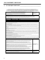
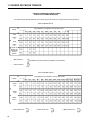
11 TORQUE CHART
22
INFORMACIÓN GENERAL
Puede disponer de manuales adicionales a través de
su distribuidor.
¡IMPORTANTE!
¡IMPORTANTE!
ESTE
MANUAL
LE
AYUDARÁ
EN
EL
MANTENIMIENTO Y FUNCIONAMIENTO SEGURO
DEL EQUIPO. LÉA COMPLETAMENTE EL MANUAL
ANTES
DE
INTENTAR
PONERLO
EN
FUNCIONAMIENTO. SI NO ENTIENDE ALGUNA DE
LAS
SECCIONES,
CONTACTE
CON
UN
DISTRIBUIDOR
AUTORIZADO
PARA
UNA
ACLARACIÓN.
Para asegurarse que es completamente consciente de
la información relativa a la seguridad y servicio, se
utilizan los siguientes dos símbolos en el manual.
! Este símbolo se utiliza en el manual para
alertarle acerca de situaciones o acciones peligrosas,
y va seguido de la palabra PELIGRO, ADVERTENCIA
o PRECAUCIÓN. PELIGRO indica peligros inmediatos
que pueden provocar daños graves o la muerte.
ADVERTENCIA indica situaciones o acciones
peligrosas que pueden provocar daños, la muerte y/o
daños en la propiedad o equipo. ADVERTENCIA
indica situaciones o acciones peligrosas que pueden
provocar daños y/o daños menores en la propiedad o
equipo.
NOTA: Esto aparece junto a la información o
instrucciones que le ayudarán para un
correcto funcionamiento y mantenimiento de
su equipo.
ESTE EQUIPO NO DEBERÍA MODIFICARSE NI
AÑADÍRSELE PIEZAS SIN LA AUTORIZACIÓN
PREVIA DEL FABRICANTE.
!
ADVERTENCIA
• La modificación de este equipo en cualquier
manera, que pueda afectar de manera adversa
su funcionamiento, rendimiento, durabilidad o
uso, puede provocar condiciones peligrosas.
Envíe sus preguntas a:
Jacobsen, a Textron Company
A la atención de Engineering
11524 Wilmar Blvd
Charlotte, NC 28273 EE.UU
INFORMACIÓN DE LAS
ESPECIFICACIONES
Toda la información incluida en este manual es la
última versión disponible en el momento de la
impresión. Textron Turf Care and Specialty Products
se reserva el derecho de realizar cambios en cualquier
momento, sin previo aviso.
Siempre que se especifique un producto de marca, se
podrá utilizar un producto equivalente si no se indica lo
contrario.
CAMBIO DE PROPIEDAD O DIRECCIÓN
!
ADVERTENCIA
• La información e instrucciones incluidas en
este manual le alertarán de determinadas
cosas que debería realizar detenidamente. Si
no lo hace, podría:
• autolesionarse o lesionar a otras personas
• lesionar a la persona que maneja el equipo
• dañar el equipo.
• Este manual incluye información acerca del
funcionamiento y servicio esencial y debe
conservarse con la unidad en todo momento,
con un acceso fácil para cualquier operador.
Impreso en EE.UU. 7–2006
Textron Turf Care and Specialty Products hace todos
los esfuerzos para mantener a los propietarios
informados de toda la información relacionada con la
seguridad. Por lo tanto, los cambios de propiedad y/o
de dirección deberían informarse al fabricante.
Su distribuidor dispone de
FORMULARIOS de
CAMBIO DE INSCRIPCIÓN que el distribuidor
completará para su registro y enviará una copia al
fabricante.
2006/42/EC Estas son las instrucciones originales
verificadas por Jacobsen a Textron company.
©2000 TEXTRON INC. • Todos los derechos reservados.
Charlotte, North Carolina
ÍNDICE
Sección
Página
1—— Modelos utilizados . . . . . . . . . . . . . . . . . . . . . . . . . . . . . . . . . . . . . . . 2
2—— Identificación. . . . . . . . . . . . . . . . . . . . . . . . . . . . . . . . . . . . . . . . . . . . 2
3—— Material y piezas de servicio . . . . . . . . . . . . . . . . . . . . . . . . . . . . . . . 2
4—— Instalación . . . . . . . . . . . . . . . . . . . . . . . . . . . . . . . . . . . . . . . . . . . . . . 3
4.1—— Desembalaje . . . . . . . . . . . . . . . . . . . . . . . . . . . . . . . . . . . . . . . . . . . 3
4.2—— Instalación de la compuerta trasera. . . . . . . . . . . . . . . . . . . . . . . . . . 3
4.3—— Instalación del modulo del elevador
Para Trucksters de julio de 1998 y anteriores . . . . . . . . . . . . . . . . . . 4
4.4—— Instalación del modulo del elevador
Para Trucksters de agosto de 1998 y posteriores . . . . . . . . . . . . . . . 4
4.5—— Instalación de los niples. . . . . . . . . . . . . . . . . . . . . . . . . . . . . . . . . . . 7
4.6—— Instalación del módulo de la horquilla direccional . . . . . . . . . . . . . . . 8
4.7—— Instalación del amortiguador de aire . . . . . . . . . . . . . . . . . . . . . . . . . 8
4.8—— Instalación de la unión inferior y los resortes de tensión superiores . 9
4.9—— Instalación de la palanca de elevación . . . . . . . . . . . . . . . . . . . . . . 10
4.10—— Instalación de la cinta transportadora . . . . . . . . . . . . . . . . . . . . . . . 11
4.11—— Direccionamiento de las mangueras hidráulicas . . . . . . . . . . . . . . . 13
4.12—— Módulo de la zapata . . . . . . . . . . . . . . . . . . . . . . . . . . . . . . . . . . . . 14
4.13—— Instalación del alineador de testigos de pinchado en hileras . . . . . 15
5—— Sistema hidráulico . . . . . . . . . . . . . . . . . . . . . . . . . . . . . . . . . . . . . . 16
6—— Ajustes. . . . . . . . . . . . . . . . . . . . . . . . . . . . . . . . . . . . . . . . . . . . . . . . 16
6.1——
6.2——
6.3——
6.4——
Nivelación del vehículo . . . . . . . . . . . . . . . . . . . . . . . . . . . . . . . . . .
Placas de extensión. . . . . . . . . . . . . . . . . . . . . . . . . . . . . . . . . . . . .
Ajuste de la cinta transportadora . . . . . . . . . . . . . . . . . . . . . . . . . . .
Ajuste del resorte de tensión . . . . . . . . . . . . . . . . . . . . . . . . . . . . . .
16
16
16
17
7—— Funcionamiento . . . . . . . . . . . . . . . . . . . . . . . . . . . . . . . . . . . . . . . . 17
8—— Mantenimiento . . . . . . . . . . . . . . . . . . . . . . . . . . . . . . . . . . . . . . . . . 18
8.1——
8.2——
8.3——
8.4——
Aceite del depósito hidráulico . . . . . . . . . . . . . . . . . . . . . . . . . . . . .
Lubricación . . . . . . . . . . . . . . . . . . . . . . . . . . . . . . . . . . . . . . . . . . .
Ajuste de la cadena del elevador. . . . . . . . . . . . . . . . . . . . . . . . . . .
Ajuste de la cinta transportadora . . . . . . . . . . . . . . . . . . . . . . . . . . .
18
18
18
18
9—— Desconexión de la Core Harvester . . . . . . . . . . . . . . . . . . . . . . . . . 19
10—— Certificado de conformidad CE . . . . . . . . . . . . . . . . . . . . . . . . . . . . . 20
11—— Cuadro de par de torsión . . . . . . . . . . . . . . . . . . . . . . . . . . . . . . . . . 22
12—— Sección de las piezas. . . . . . . . . . . . . . . . . . . . . . . . . . . . . . . . . . . . 24
12.1—— Funda y paneles del elevador . . . . . . . . . . . . . . . . . . . . . . . . . . . . .
12.2—— Cadena, palancas y piñones . . . . . . . . . . . . . . . . . . . . . . . . . . . . . .
12.3—— Sistema hidráulico . . . . . . . . . . . . . . . . . . . . . . . . . . . . . . . . . . . . . .
12.4—— Soporte de la cinta transportadora y elevador. . . . . . . . . . . . . . . . .
12.5—— Bastidor principal, asa y tubo de unión . . . . . . . . . . . . . . . . . . . . . .
12.6—— Tubo de empuje, zapata y cuchilla para el alineador . . . . . . . . . . .
12.7—— Extensiones de caja y cinta transportadora. . . . . . . . . . . . . . . . . . .
12.8—— Pivote direccional, eje y neumáticos . . . . . . . . . . . . . . . . . . . . . . . .
24
26
28
30
32
34
36
38
1
1 MODELOS UTILIZADOS
1
MODELOS UTILIZADOS__________
El accesorio de la Core Harvester, pieza número
4119652, puede utilizarse en los modelos Turf
Truckster 84043, 84044, 84056, 84057, 84061,
898530, 898532, 898543, 898627, 898628, 898630,
898632, 898633, 898634, 898636, 898637, 898650,
898652, 898659, 898662, 898663, 898664, 898684,
898685, 898656, 898657, y 898658. Consulte a
continuación si el Turf Truckster necesita un kit de
conversión.
2
IDENTIFICACIÓN _______________
El número de pieza y el número de serie del accesorio
están imprimidos en la etiqueta de la placa del
fabricante situada en el bastidor principal (Ver fig. 1).
El número de serie y el número de la piezaDEBEN
aparecer en toda la documentación relacionada con
este accesorio.
ETIQUETA DE LA PLACA
DEL FABRICANTE
Instalación en neumáticos traseros pequeños de los
modelos 898530, 898532, 898543, 898630 y 898632
de Cushman Turf Truckster. NO instale la Core
Harvester en ninguno de los modelos de neumático
pequeños equipados con una cabina o un ROPS
(Pieza número 892689).
Kits de conversión:
• 891252 Kit de horquilla: Necesario
• 887933 Conjunto de transmisión auxiliar: Necesario
para las unidades 8610 y anteriores
• 888453 Kit de actualización hidráulica: Necesario
para las unidades 8910 y anteriores
• 889558 Kit de acoplador remoto: Necesario para las
unidades 9010 y anteriores
Instalación en los neumáticos traseros grandes más
antiguos (23x13-10) de los modelos 898530, 898532,
898630, 898632, 898634, 898636 y 898637 de Turf
Truckster. NO instale la Core Harvester en ninguno de
los modelos de neumático grandes equipados con una
cabina o un ROPS (Pieza número 892689).
•
No se necesitan kits de conversión.
Instalación en los Turf Trucksters más nuevos con
neumáticos grandes (23 x 13-10) modelos 898650,
898652, 898659, 898662, 898663, 898664, 898684,
898685, 898656, 898657, y 898658.
La Core
Harvester PUEDE en cualquiera de estos modelos
equipados con un ROPS superior (Pieza número
894761).
•
No se necesitan kits de conversión.
2
Figura 1
3
MATERIAL Y PIEZAS DE SERVICIO
Descripción .................................... Número de pieza
Palanca, cadena del elevador........................... 832334
Acoplador, cadena ............................................ 832421
Unión, cadena ................................................... 832422
Unión, conexión ................................................ 832423
Aceite hidráulico Turf Protector™
9,7 l ..................................................................... 65363
18,9 l ................................................................... 65352
208 l .................................................................... 65354
INSTALACIÓN 4
4
4.1
INSTALACIÓN__________________
DESEMBALAJE _______________________
1. Quite la correa abrazadera que se usa para
asegurar el elevador y las piezas sueltas al palet.
Quite todas las piezas sueltas y cajas del palet de
transporte, exceptuando el módulo del elevador.
Quite cualquier correa abrazadera que pueda
estar fijando el módulo del tubo de empuje al
elevador (Ver Fig. 2).
!
PRECAUCIÓN
Mantenga sus manos y sus dedos alejados de
los puntos de apriete. Debido a que estas piezas
pivotan, es posible que se dañe las manos y/o
dedos a la hora de elevar o balancear el módulo
del elevador.
2. Haga girar el módulo del tubo de empuje hacia la
parte frontal del elevador y apoye el tubo de
empuje en el suelo. Gire el elevador 180_ de modo
que el amortiguador y el pivote principal se
encuentren en la parte inferior (el amortiguador, el
bastidor principal y el eje del pivote principal
pivotarán a menos que estén fijados al elevador,
por ello es posible que desee atar unas bandas o
correas a estos elementos para que no pivoten
cuando se está girando o elevando el elevador)
(Ver Fig. 3).
NOTA: Cualquier referencia a la parte delantera,
trasera, izquierdao derecha del vehículo vendrá
siempre determinada por la posición del
asiento del operador.
3. Quite el panel de la parte izquierda del vehículo.
4. Quite el cinturón para caderas izquierdo del
Trucksters de julio de 1998 y anteriores.
¡IMPORTANTE!
SI SU VEHÍCULO ESTÁ EQUIPADO CON UN
CONJUNTO DE CAJA PEQUEÑA O COMPUERTA
TRASERA, PIEZA NÚM. 885488, DEBERÁ QUITAR
ESTA COMPUERTA TRASERA. SE MOVERÁ A LA
PARTE DERECHA DE LA CAJA PEQUEÑA.
OBSERVE LA POSICIÓN Y GUARDE TODAS LAS
PIEZAS CUANDO LAS QUITE.
4.2 INSTALACIÓN
DE
LA
COMPUERTA
TRASERA
1. Marque la ubicación tal y como se muestra en la
parte inferior del panel lateral derecho de la caja
(Ver Fig. 4). Perfore un orificio de un diámetro de
11/32” (9 mm) en la caja. El soporte estará
ubicado en la misma ubicación que la de la parte
izquierda. Asegúrela con un tornillo 5/16-18 x 5/8
(Pieza Núm. 306555) y una tuerca de fijación del
reborde (Pieza Núm. 548911).
REF. ABRAZADERA 823038
ELEVE Y GIRE
EL TUBO DE EMPUJE
Y APÓYELO EN EL SUELO
REF. PARTE INFERIOR
DE LA CAJA
TUBO DE EMPUJE
Figura 2
SE MUESTRA ÚNICAMENTE
A MODO DE REFERENCIA
GIRE EL ELEVADOR 180°
EL ELEVADOR SE
TRANSPORTA BOCA ABAJO.
GIRE EL ELEVADOR
PARA INSTALARLO
EN EL VEHÍCULO
ADECUADAMENTE
Figura 3
REF. POSTE
FRONTAL DERECHO
Figura 4
2. Inserte la unidad de la placa dentro del poste
frontal derecho de la caja. Asegúrelo con la
tornillería existente. Perfore algunos orificios si es
necesario.
3. Fije el soporte del pivote/asa a los orificios
superiores existentes en el poste usando la
tornillería existente.
4. Quite la compuerta trasera de la parte posterior
derecha de la caja pequeña. Instale el enganche
de la compuerta trasera (Pieza Núm. 830950).
Use la tornillería existente.
5. Inserte la varilla de la compuerta trasera a través
del soporte de la caja. Instale el cojinete, la
arandela y el resorte en la varilla e insértela a
través del poste de la caja y del pivote del asa.
6. Monte la varilla de la compuerta trasera al nuevo
enganche con un arandela plana y el nuevo
pasador abierto (Pieza Núm. 306328).
7. Vuelva a empujar la arandela plana contra el
resorte e inserte el nuevo pasador abierto (Pieza
Núm. 306328) a través de la varilla.
3
4 INSTALACIÓN
4.3
INSTALACIÓN DEL MÓDULO DEL
ELEVADOR PARA TRUCKSTERS DE JULIO
DE 1998 Y ANTERIORES________________
!
ADVERTENCIA
El módulo del elevador es pesado y se requieren
dos o más personas para levantarlo. Utilice unas
técnicas apropiadas de elevación para evitar
lesiones.
1
2
Si se usa una grúa para elevar la unidad, mantenga
los pies y las manos fuera de debajo del elevador
mientras éste está siendo levantado.
Asegúrese de que el módulo del tubo de
empuje está colocado hacia delante.
Afloje la tornillería que asegura la caja
hidráulica de la pared de soporte para obtener
acceso a la tornillería de fijación del marco del
bastidor principal.
1. Coloque el soporte de montaje superior del bastidor
principal en una posición que quede FRENTE a la
pared de soporte del vehículo. A mismo tiempo
coloque el soporte de montaje inferior en la posición
en el RIEL DEL BASTIDOR.
Use dos tornillos, 5/16-18 x 1 (Pieza Núm. 306416),
cuatro arandelas planas, dos arandelas de fijación y
tuercas para asegurar el soporte de montaje superior
a la pared de soporte (Ver Fig. 5). Ajuste la tornillería
de la caja hidráulica.
2. Eleve y apoye el extremo inferior del elevador lo
suficiente como para que el soporte de montaje
inferior se pueda sujetar con soportes en su lugar
contra el riel del bastidor del vehículo, con el borde
superior de el soporte abajo contra la parte superior
del riel del bastidor. Sujete con soportes en su lugar.
Use los orificios del soporte a modo de plantilla.
Taladre cuatro (4) orificios de 10 mm a través del riel
del bastidor (Ver Fig. 6). Asegure con cuatro
tornillos, 3/8-16 x 1 (Pieza Núm. 306414), arandelas
de fijación y tuercas. Quite los soportes y el soporte
del extremo inferior del elevador.
4134
Figura 6
1. Soporte de montaje inferior
2. Riel del bastidor del vehículo
NOTA:
INSTALACIÓN
DEL
MODULO
DEL
ELEVADOR
PARA
TRUCKSTERS
DE
AGOSTO DE 1998 Y POSTERIORES _______
1. Instale el soporte de montaje negra (Pieza Núm.
894698) en los orificios existentes del bastidor del
vehículo tal y como se muestra en la Figura 1.
Asegúrelo usando dos (2) tornillos M10-1.50 x 30
(Pieza Núm. 452400) y dos (2) tuercas M10-1.50
(Pieza Núm. 450454) (Ver Fig. 7 y 8).
4.4
Nº PIEZA 450454
SOPORTE DE MONTAJE
Nº PIEZA 894698
Nº PIEZA
452400
Figura 7
1
2
4133
Figura 5
1. Pared de soporte
2. Soporte de montaje superior del bastidor
principal
4
SOPORTE DE MONTAJE
Figura 8
INSTALACIÓN 4
2. Acople el soporte verde (montaje del bastidor a
ROPS, Pieza Núm. 844797) al soporte de montaje
tal y como se muestra en la Figura 3. Asegúrela
usando dos (2) tornillos M10-1.50 x 30 (Pieza
Núm. 452400). No apriete ya que es necesario
que la tornillería esté floja para su posterior ajuste
cuando el elevador esté instalado (Ver Fig. 9 &
10).
3. Instale el soporte de sujeción (Pieza Núm.
844798) y la placa de fijación (Pieza Núm.
844668) en la estructura ROPS justo a la izquierda
del asa de mano situada a la izquierda del
vehículo (Ver Fig. 11 y 12).
MONTAJE DEL
BASTIDOR A ROPS
Nº PIEZA 844797
Nº PIEZA
452400
Figura 9
4. Asegure usando dos (2) tornillos M8-1.25 x 25
(Pieza Núm. 452389) y tuercas de brida M8-1.25
(Pieza Núm. 450453). No apriete ya que deberá
apretarlos cuando el elevador esté montado (Ver
Fig. 11 y 12).
MONTAJE DEL
BASTIDOR A ROPS
Nº PIEZA
450453
Figura 10
PLACA DE FIJACIÓN
Nº PIEZA 844798
PLACA DE FIJACIÓN
Nº PIEZA 844668
EL ELEVADOR SE
INSTALARÁ EN
ESTOS DOS (2)
ORIFICIOS
Nº PIEZA
452389
Figura 11
Figura 12
5
4 INSTALACIÓN
!
ADVERTENCIA
El módulo del elevador es pesado y se requieren
dos o más personas para levantarlo. Utilice unas
técnicas apropiadas de elevación para evitar
lesiones.
Si se usa una grúa para elevar la unidad,
mantenga los pies y las manos fuera de debajo
del elevador mientras éste está siendo
levantado.
MONTAJE DEL
BASTIDOR A ROPS
ABRAZADERA DE MONTAJE
INFERIOR DEL ELEVADOR
Figura 13
5. Coloque el elevador de modo que el soporte de
montaje inferior del elevador quede sobre el
montaje del bastidor a ROPS (Ver Fig. 13).
6. Eche el elevador hacia atrás hasta que el soporte
de montaje superior se encuentre frente a la parte
frontal de la placa de fijación (Ver Fig. 14).
7. Fije el elevador al soporte inferior usando cuatro
(4) tornillos M10-1.50 x 70 (Pieza Núm. 452404).
No apretar.
8. Si es necesario, coloque bloques (o equivalentes)
debajo del elevador a modo de apoyo mientras lo
está montando.
9. Asegure el soporte de montaje superior del
elevador a la placa de fijación usando dos (2)
tornillos M8-1.25 x 25 (Pieza Núm. 452389) y
tuercas de brida (Pieza Núm. 450453). Comience
a apretar la tornillería como sigue:
10. Apriete los dos tornillos que aseguran la placa de
fijación y el soporte a la parte superior de ROPS.
Posteriormente, apriete la tornillería que fija el
elevador a la placa de fijación.
Figura 14
PLACA Y SOPORTE
DE FIJACIÓN
Nº PIEZA 452404
Nº PIEZA 452389
MONTAJE DEL
BASTIDOR A ROPS
EL BASTIDOR PRINCIPAL
DE LA CORE HARVESTER
SE MUESTRA SIN EL
ELEVADOR, ÚNICAMENTE
A MODO DE REFERENCIA
11. A continuación, apriete la tornillería que fija el
soporte inferior del elevador al montaje ROPS.
Nº PIEZA 452404
12. Luego apriete la tornillería que fija el montaje del
bastidor a ROPS a el soporte de montaje negra
que está fijada al bastidor del vehículo.
6
Figura 15
INSTALACIÓN 4
4.5
INSTALACIÓN DE LOS NIPLES __________
TUBO DE EMPUJE
NOTA:
Las fotografías que se muestran en las
siguientes
figuras
se
muestran
únicamente a modo de referencia, a pesar
de que muestran zonas de la Core
Harvester que ya están montadas. Por
favor, siga las instrucciones tal y como se
describe y se hace referencia en cada
paso.
1. Eleve el tubo de empuje lo suficiente como para
despejar los dos orificios roscados que se
encuentran en cada uno de los laterales de la
parte inferior del elevador (Ver Fig. 16).
2. Instale un niple (Pieza Núm. 832430) del kit de
accesorios en cada lado del elevador y apriete (es
posible que desee aplicar una fina capa de grasa
en las roscas del niple antes de instalarlo y
apretarlo usando una llave de tuberías ajustable.
EL TUBO DE EMPUJE DEBE
MANTENERSE SUFICIENTEMENTE
ELEVADO PARA LIMPIAR
LOS ORIFICIOS ROSCADOS
NIPLE DE TUBO
Figura 16
NIPLE DE TUBO
TUBO DE EMPUJE
3. Baje el tubo de empuje de modo que quede
apoyado sobre los niples (Ver Fig. 17).
4. El módulo del pivote direccional y del tubo de
empuje se encuentran fijados al módulo del
pasador del pivote principal (Ver Fig. 18). El
pasador ya está insertado a través de los montajes
del tubo de empuje y del módulo del pivote
direccional pero se envía sin la arandela y sin el
pasador abierto.
5. Apriete el pasador del pivote desde el lateral del
vehículo, hacia afuera a través de todos los
cojinetes que fijan el módulo del pivote direccional
y el tubo de empuje al pasador del pivote principal.
Fíjelo usando una (1) arandela grande (Pieza
Núm. 832479) y un pasador abierto (Pieza Núm.
325109).
Figura 17
MÓDULO DEL
PIVOTE DIRECCIONAL
FIJE EL EXTREMO DEL
PASADOR DE PIVOTE
CON EL PASADOR
ABIERTO Y LA
ARANDELA
PASADOR DEL
PIVOTE PRINCIPAL
Figura 18
7
4 INSTALACIÓN
4.5
INSTALACIÓN DEL MÓDULO
HORQUILLA DIRECCIONAL
DE
LA
MÓDULO DEL
PIVOTE DIRECCIONAL
1. Localice el módulo de la horquilla direccional
(Pieza Núm. 890118) en el kit de accesorios.
Coloque la abertura de las ranuras que se
encuentran en la parte inferior de la horquilla hacia
el vehículo e inserte la caña de la horquilla en el
tubo de montaje que se encuentra en el extremo
del módulo del pivote direccional (Ver Fig. 19). Fije
usando un (1) aro de fijación (Pieza Núm.
548349). Baje con cuidado el módulo de la
horquilla direccional, permitiendo que la horquilla
yazca sobre el suelo.
MÓDULO DE LA
HORQUILLA
DIRECCIONAL
INSERTE LA CAÑA DE LA
HORQUILLA EN EL TUBO
DEL PIVOTE DIRECCIONAL
Figura 19
2. Monte el neumático y la llanta en el montaje del
cubo y el eje. El eje y el cubo se instalarán desde
el lateral de la llanta de frente al vástago de la
válvula (Ver Fig. 20). Inserte los espárragos de
montaje de la rueda a través de los orificios de
montaje y asegúrelos usando cuatro (4) tuercas de
retención de la rueda (Pieza Núm. 805860).
3. Aplique a las tuercas de retención de la rueda un
par de torsión de 70-100 ft. lbs. (95 a 140 N×m).
4. Instale la rueda y el eje en el módulo de la
horquilla direccional deslizando el eje contra la
parte trasera de la ranura. Asegúrese de que la
tornillería del eje está lo suficientemente floja
como para permitir el montaje del marco de la
horquilla entre las dos arandelas grandes que se
encuentran a cada lado de la horquilla (Ver Fig.
21) o quite la tuerca, la arandela de fijación y una
arandela grande de cada extremo lateral del eje.
Deslice la rueda asegurándose de de mantener
una (1) arandela grande dentro del marco de la
horquilla y una arandela grande fuera del marco
de la horquilla. Sustituya la tornillería.
5. Aplique a las tuercas de retención del eje un par
de torsión de 70-100 ft. lbs. (95 a 140 N×m).
4.5
INSTALACIÓN DEL AMORTIGUADOR DE
AIRE
1. Utilizando la tornillería que se suministra, acople el
extremo inferior del amortiguador en el espárrago
del módulo del pivote direccional (consulte las
piezas en la ilustración de la página 30).
2. Utilizando la tornillería que se suministra, acople el
extremo superior del amortiguador en el espárrago
del módulo del bastidor principal (consulte las
piezas en la ilustración de la página 30).
8
MÓDULO DEL
EJE Y DEL CUBO
TUERCA DE
RETENCIÓN
DE LA RUEDA
INSTÁLELO EN EL LATERAL
DE LA LLANTA OPUESTO
AL VÁSTAGO DE LA VÁLVULA
PARTE DELANTERA
DEL VEHÍCULO
VÁTAGO DE
LA VÁLVULA
Figura 20
COMPRUEBE TAMBIÉN QUE DISPONE
DE UNA ARANDELA GRANDE EN EL
INTERIOR Y EXTERIOR DEL MARCO
DE LA HORQUILLA EN EL LADO OPUESTO
ARANDELA GRANDE EN
LA PARTE INTERIOR DEL
MARCO DE LA HORQUILLA
MÓDULO DE LA
HORQUILLA
DIRECCIONAL
ARANDELA GRANDE
EN LA PARTE EXTERIOR
DEL MARCO DE LA
HORQUILLA
DESLICE EL EJE HACIA LA
PARTE POSTERIOR DE LA RANURA
Figura 21
INSTALACIÓN 4
4.5
INSTALACIÓN DE LA UNIÓN INFERIOR Y
LOS RESORTES DE TENSIÓN SUPERIORES
1. Eleve y apoye el extremo inferior del elevador.
Localice el resorte de unión inferior 10 5/8” (270
mm) (Pieza Núm. 832525) en el kit de accesorios.
Conecte un extremo del resorte al soporte de la
unión inferior tal y como se muestra en la Figura
22 (la unión inferior se encuentra hacia la parte
frontal inferior del elevador, cerca del suelo del
vehículo, tal y como se muestra en la Figura 23).
RESORTE DE
UNIÓN INFERIOR
(270 mm DE LARGO)
CONÉCTELO A LA
ABRAZADERA EN
LA UNIÓN INFERIOR
RESORTE DE UNIÓN INFERIOR
(270 mm DE LARGO)
TORNILLO
DE AJUSTE
TUERCA EN
CADA LADO DE
LA ABRAZADERA
CENTRAL
PARTE DELANTERA
DEL VEHÍCULO
UNIÓN INFERIOR
Figura 24
RESORTE DE
TENSIÓN SUPERIOR
PARTE DELANTERA
DEL VEHÍCULO
BARRA DE MONTAJE
DEL RESORTE EN
LA UNIÓN SUPERIOR
VISTO DESDE EL LADO
DEL PASAJERO DEL VEHÍCULO
Figura 22
EL SOPORTE EN LA UNIÓN
INFERIOR ESTÁ SITUADO EN EL LADO DEL
REMOLQUE MIRANDO HACIA EL VEHÍCULO
EL RESORTE DE UNIÓN INFERIOR
INSTALADO SE MUESTRA
PARA INDICAR SU POSICIÓN
Figura 23
2. Conecte el otro extremo del resorte al tornillo de
ajuste que se encuentra en el soporte de centro
(Ver Fig. 24).
Figura 25
5. Conecte el otro extremo del resorte al tornillo de
ajuste que se encuentra en el soporte de centro tal
y como se muestra en la Figura 26. Quite el tornillo
(Pieza Núm. 832438) y dos (2) tuercas 3/8-16
(Pieza Núm. 304632) del Kit de Accesorios e
instálelos en el soporte de centro. Asegúrese de
mantener una tuerca a cada lado del soporte. El
resorte se ajustará más adelante.
TORNILLO
DE AJUSTE
RESORTE DE
TENSIÓN SUPERIOR
(391 mm DE LARGO)
3. Utilizando el tornillo (Pieza Núm. 832438) y dos (2)
tuercas 3/8-16 (Pieza Núm. 304632) del Kit de
Accesorios, instálelos en el soporte de centro.
Asegúrese de mantener una tuerca a cada lado
del soporte. El resorte se ajustará más adelante.
4. Conecte un extremo del resorte de tensión largo
de la parte superior 15 3/8” (391 mm) (Pieza Núm.
832322) a la barra de montaje de la unión superior
(Ver Fig. 25).
PARTE DELANTERA
DEL VEHÍCULO
TUERCA EN CADA LADO
DE LA SOPORTE DE CENTRO
Figura 26
9
4 INSTALACIÓN
4.5
INSTALACIÓN
ELEVACIÓN
DE
LA
PALANCA
DE
PALANCA
DE ELEVACIÓN
1. La palanca de elevación se montará directamente
en el eje, en frente del soporte de centro (el
soporte central es el mismo soporte al que se
fijaron previamente los resortes y los dos tornillos
de ajuste).
2. Localice la palanca de elevación (Pieza Núm.
888271) y el resorte pequeño de la palanca (Pieza
Núm. 812368) en el Kit de Accesorios.
3. Aplique una pequeña cantidad de lubricante a
base de litio en el eje de montaje de la palanca de
elevación y deslice la palanca en el eje. El soporte
soldado en la parte inferior de la palanca deberá
colocarse hacia la parte frontal del vehículo (Ver
Fig. 27).
4. Asegure la palanca de elevación usando una (1)
arandela de retención (Pieza Núm. 548165) y un
(1) pasador abierto (Pieza Núm. 304635).
FIJE EL
RESORTE
DESLICE LA
PALANCA
HACIA EL EJE
SOPORTE
CENTRAL
Figura 27
PALANCA
DE ELEVACIÓN
5. Acople un extremo del resorte de la palanca a la
lengüeta de montaje situada en la parte inferior de
la palanca y acople el otro extremo del resorte al
orificio situado en el soporte de centro (Ver Fig. 27
y 28).
Figura 28
10
INSTALACIÓN 4
4.5
INSTALACIÓN
DE
TRANSPORTADORA
LA
CINTA
SOPORTE DE BARRAS
1. Localice la cinta transportadora, el soporte de la
cinta transportadora (Pieza Núm. 894845) y el
soporte de barra (Pieza Núm. 888274) en el Kit de
Accesorios.
2. Coloque el soporte de barra en el porta barras
colocado en la parte trasera lateral de la caja (Ver
Fig. 29). Si su vehículo está equipado con una
caja que no sea la caja pequeña, el soporte de
barra se instalará en medio del porta barras (el
porta barras estará en realidad más cerca a la
parte trasera que al centro de la caja).
SOPORTE DE BARRAS
DE LA PARTE POSTERIOR
IZQUIERDA (CAJA CORTA)
SOPORTE
DE BARRAS
(CAJA GRANDE)
Figura 29
3. Asegure el soporte de barra a la caja lateral
usando un (1) tornillo 3/8-16 x 2 1/2” (Pieza Núm.
301431), una (1) arandela plana 3/8 (Pieza Núm.
306981), una (1) arandela de fijación 3/8 (Pieza
Núm. 120177) y una (1) tuerca 3/8-16 (Pieza Núm.
306562).
4. Instale el soporte de la cinta transportadora (Pieza
Núm. 894845) colocando el extremo del tubo 90_
en el porta barras frontal situado en el lateral
izquierdo de la caja y colocando el tubo horizontal
en la horquilla del soporte de barra tal y como se
muestra en la Figura 30.
5. Asegure la parte frontal del soporte de la cinta
transportadora al lateral de la caja usando un (1)
tornillo 3/8-16 x 2 1/2” (Pieza Núm. 301431), una
(1) arandela plana 3/8 (Pieza Núm. 306981), una
(1) arandela de fijación 3/8 (Pieza Núm. 120177) y
una (1) tuerca 3/8-16 (Pieza Núm. 306562).
6. Asegure la parte lateral trasera del soporte de la
cinta transportadora a la horquilla del soporte de
barra que se ha instalado previamente (Ver Fig.
31). Inserte un (1) tornillo (1) 3/8-16 x 2 3/4” (Pieza
Núm. 307776) a través de los orificios de la
horquilla y fíjelo usando una (1) arandela plana 3/8
(Pieza Núm. 306981), una (1) arandela de fijación
3/8 (Pieza Núm. 120177) y una (1) tuerca 3/8-16
(Pieza Núm. 306562).
SOPORTE PARA LA CINTA
TRANSPORTADORA
Nº PIEZA 894845
COLOQUE EL
EXTREMO DEL
SOPORTE EN
LA HORQUILLA
HACIA ADELANTE,
PORTA BARRAS
IZQUIERDO
Figura 30
SE MUESTRA LA CAJA PEQUEÑA
LA INSTALACIÓN SERÁ LA MISMA PARA
LA CAJA GRANDE; LA ÚNICA DIFERENCIA
SERÁ LA POSICIÓN DEL PORTA BARRAS
Figura 31
11
4 INSTALACIÓN
7. Monte la cinta transportadora en el soporte de la
cinta
transportadora.
Coloque
la
cinta
transportadora en las placas de montaje de la
cinta transportadora usando la ilustración de la
Figura 32 a modo de referencia, dependiendo de
la caja que tenga su vehículo.
CAJA GRANDE
8. Asegure usando cuatro (4) tornillos M8-1.25 x 25
(Pieza Núm. 452389) y cuatro (4) tuercas de brida
M8-1.25 (Pieza Núm. 450453). Coloque la cinta
transportadora hasta que los tornillos se
encuentren frente a la parte trasera de las ranuras
y apriete la tornillería.
9. Es posible que tenga que ajustar la posición de la
cinta transportadora mientras usa la Core
Harvester por primera vez. Los testigos de
pinchado deberán caer desde el elevador al centro
de la cinta transportadora. Es normal que también
algunos de los testigos de pinchado caigan fuera
de los laterales del conducto, pero no quiere que
los núcleos llenen en exceso la cinta
transportadora. Ajuste según sea necesario.
10. Para ajustar la cinta transportadora, afloje los
cuatro (4) tornillos montados en la cinta
transportadora y deslice la cinta transportadora
hasta la ubicación deseada. Apriete la tornillería
cuando haya colocado bien la cinta transportadora
(Ver Fig. 33).
12
CAJA PEQUEÑA
Figura 32
CINTA TRANSPORTADORA
SOPORTE PARA LA
CINTA TRANSPORTADORA
Figura 33
INSTALACIÓN 4
4.11 DIRECCIONAMIENTO DE LAS MANGUERAS
HIDRÁULICAS
NOTA: Aplique Cinta Sellante de Teflón a todas las
juntas del sistema hidráulico.
No apriete en exceso los accesorios
hidráulicos. Apriete las juntas hasta que no
goteen. Su las aprieta demasiado puede
provocar daños a los accesorios o escapes.
Direccione la manguera de modo que las
piezas de plástico ni se muevan ni se
calienten. Use uniones de cables para
mantener las mangueras en su posición.
Limpie todas las ranuras de los accesorios hidráulicos
(partes con racores macho así como partes con
racores hembra) con un trapo limpio (sin pelusas)
antes aplicar la cinta de teflón.
1. Instale el accesorio hidráulico 90_ (Pieza Núm.
827395) del Kit de Accesorios en la parte trasera
del motor de la cinta transportadora. Apriete el
accesorio de modo que el conector de la
manguera se encuentre boca abajo y ligeramente
girado hacia la caja (Ver Fig. 34).
2. Instale el accesorio hidráulico recto (Pieza Núm.
832396) del Kit de Accesorios en la parte inferior
del motor de la cinta transportadora y apriete (Ver
Fig. 34).
NIPLE
Nº PIEZA 105706
ACOPLADOR
DE JUNTA SECA
Nº PIEZA 894701
3. Aplique cinta de teflón a todas las ranuras del niple
del tubo hidráulico (Pieza Núm. 105706) del Kit e
instale el niple del tubo en el accesorio recto que
se ha conectado previamente a la parte inferior del
motor.
4. Localice un (1) acoplador hembra de junta seca
(Pieza Núm. 894701) del Kit. Instale el acoplador
en el extremo del niple del tubo que se ha
instalado previamente (asegúrese de que la cinta
de teflón se ha aplicado al niple).
5. Aplique dos vueltas de una cinta de teflón nueva a
la manguera e instale un (1) acoplador hidráulico
macho (Pieza Núm. 894702) del Kit. Direccione la
manguera al motor de la cinta transportadora y
conecte el acoplador macho al acoplador hembra
situado en la parte inferior del motor (Ver Fig. 35).
6. Aplique cinta de teflón a las ranuras de los
accesorios de 45 grados (Pieza Núm. 521949) e
instale y fije los accesorios al motor del elevador
(Ver Fig. 35).
7. Localice la manguera hidráulica larga de 762 mm
en el Kit , aplique cinta de teflón a uno de los
extremos de la manguera e instale el accesorio 45
de grados en el motor del elevador.
ACCESORIO 90º
Nº PIEZA 827395
ACCESORIO RECTO
Nº PIEZA 832396
Figura 34
MOTOR DEL
ELEVADOR
MOTOR DE LA CINTA
TRANSPORTADORA
ACOPLADOR HEMBRA
Nº PIEZA 894701
ACCESORIO 45º
ACOPLADOR MACHO
Nº PIEZA 894702
Figura 35
8. Aplique cinta de teflón en el otro extremo de la
manguera. Localice un (1) acoplador hembra de
junta seca (Pieza Núm. 894701) del Kit e instálelo
en un extremo de la manguera.
13
4 INSTALACIÓN
9. El acoplador estará conectado a la manguera que se
ha quitado del acoplador hidráulico situado en la
parte superior izquierda en la caja de control
hidráulico ubicada en la pared de detección,
directamente detrás del asiento del conductor.
10. Desconecte la manguera del acoplador superior de la
caja de control (Ver Fig. 36) y acóplela al acoplador
que se ha instalado previamente en la manguera de
30” (762 mm) procedente del puerto inferior del motor
del elevador.
11. Localice la manguera larga de 56” (1422 mm) (Pieza
Núm. 832398) en el Kit de Accesorios. Aplique cinta
de teflón a las ranuras del otro extremo de la
manguera. Conecte la manguera al accesorio de 90_
situado detrás del motor de la cinta transportadora.
12. Aplique cinta de teflón a las ranuras del otro extremo
de la manguera e instale otro acoplador macho de
junta seca (Pieza Núm. 894702) del kit en el extremo
de la manguera.
13. Direccione la manguera a la caja de control hidráulico
y conecte el acoplador macho al acoplador hembra
situado en la superior izquierda de la caja de control
tal y como se muestra en la Figura 37.
14. Use uniones de cables o un equivalente para
mantener las mangueras fuera de las piezas en
movimiento ya que los puntos de apriete y/o piezas
pueden calentarse.
DESCONECTE LA MANGUERA DEL
ACOPLADOR SUPERIOR DE LA CAJA
DE CONTROL Y ACÓPLELA AL
ACOPLADOR DE LA MANGUERA
DE 762 MM
4.11 MÓDULO DE LA ZAPATA _______________
1. Localice los dos (2) refuerzos de zapata (Pieza Núm.
832391, el refuerzo izquierdo y la Pieza Núm. 832392
(refuerzo derecho) y el módulo de la zapata (Pieza
Núm. 887963) en el Kit de Accesorios.
2. Quite la tuerca del orificio de montaje superior situado
en el cojinete de la parte inferior izquierda del elevador
(Ver Fig. 38).
3. Instale el refuerzo izquierdo de la zapata en el tornillo
del cojinete y fíjelo con la tornillería que ha quitado
anteriormente. NO apretar. Instale el refuerzo
derecho de la zapata en el lado contrario del elevador
usando el mismo procedimiento que para el refuerzo
izquierdo.
4. Acople el módulo de la zapata a la parte inferior del
elevador fijándolo con cuatro (4) tornillos 5/8-18 x 5/8
(Pieza Núm. 306555) y tuercas de fijación del reborde
5/8-18 (Pieza Núm. 548911). NO apriete la tornillería
en este momento.
5. Localice los dos (2) pernos de transporte 5/16-18 x 3/
4 (Pieza Núm. 800358) y las dos (2) tuercas de
fijación del reborde (Pieza Núm. 548911) en el Kit de
Accesorios.
6. Inserte el perno de transporte de la parte inferior de la
zapata a través del orificio de montaje del refuerzo de
la zapata tal y como se muestra en la Figura 39. Fíjelo
con las tuercas de fijación del reborde.
7. Apriete la tornillería asegurando el módulo de la
zapata al elevador y apriete la tornillería fijando los
refuerzos de la zapata a la brida del cojinete y a la
zapata.
RETIRE LA TUERCA
SUPERIOR DE LA BRIDA
DEL COJINETE E
INSTALE LA FIJACIÓN
FIJAR AQUÍ
ZAPATA DEL
LADO IZQUIERDO
MÓDULO DE
LA ZAPATA
FIJAR AQUÍ
Figura 36
Figura 38
MOTOR DEL
ELEVADOR
MANGUERA
DE 762 mm
MOTOR DE LA CINTA
TRANSPORTADORA
MANGUERA
DE 1422 mm
PERNO DE
TRANSPORTE
Figura 37
Figura 39
14
INSTALACIÓN 4
4.11 INSTALACIÓN
DEL
ALINEADOR
TESTIGOS DE PINCHADO EN HILERAS
DE
PASADOR DEL PIVOTE
EN EL TUBO DE EMPUJE
TUBO DE EMPUJE
1. Instalar el módulo (cuchilla) de hilera en el tubo de
empuje. Deslice el módulo de hilera en el pasador
del pivote del tubo de empuje tal y como se
muestra en la Figura 39. Fíjelo usando una (1)
horquilla (Pieza Núm. 809265) del Kit de
Accesorios.
2. Localice la placa de acoplamiento de cuchilla
(Pieza Núm. 832309) en el kit de accesorios.
Alinee las etiquetas de montaje en los extremos de
las cuchillas con los orificios exteriores situados en
la placa de acoplamiento de cuchilla (Ver Fig. 41).
3. Deslice una (1) arandela plana (Pieza Núm.
306981) y un (1) cojinete (Piezas Núm. 521679)
en uno de los tornillo 3/8-16 x 1 (Pieza Núm.
306414). Inserte el tornillo, la arandela y el cojinete
(desde la parte superior) a través de los orificios
de montaje bien de la parte izquierda o derecha de
la placa de acoplamiento de cuchilla. Fíjelo
usando (1) una arandela de fijación 3/8 (Pieza
Núm. 120177) y una (1) tuerca 3/8-16 (Pieza Núm.
306562).
ALINEADOR DE HILERA
Figura 40
BARRA DE
ACOMPLAMIENTO
Nº PIEZA 844798
PLACA
DE SOPORTE
LENGÜETA DE
MONTAJE
EN EL MÓDULO
DE LA CUCHILLA
PLACA DE
ACOPLAMIENTO
DE LA CUCHILLA
Nº PIEZA 844798
4. Repita este procedimiento en el lado contrario de
la placa de acoplamiento de cuchilla y apriete la
tornillería.
5. Localice la barra de acoplamiento (Pieza Núm.
832310) en el kit de accesorios. Inserte el extremo
roscado de la varilla a través del orificio del
soporte que está unida al tubo de empuje (Ver Fig.
41).
Figura 41
HORQUILLA
6. Cuando la sección roscada de la barra de
acoplamiento pase a través del soporte, rosque
una (1) tuerca 7/16-14 (Pieza Núm. 304364) en la
barra de acoplamiento hasta que la tuerca entre
en contacto con la montura de la barra de
acoplamiento,
7. Inserte el extremo roscado de la barra de
acoplamiento en el orificio central de la placa de
acoplamiento de cuchilla (Ver Fig. 41) y fíjelo
usando una tuerca 7/16-14, Pieza Núm. 304364
(cuando haya fijado la tornillería, la parte de abajo
de la segunda tuerca deberá encontrarse a la
misma altura que el extremo de la barra de
acoplamiento).
Figura 42
8. Fije la barra de acoplamiento al soporte usando
una (1) horquilla (Pieza Núm. 822529) (Ver Fig.
42).
15
5 SISTEMA HIDRÁULICO
5
SISTEMA HIDRÁULICO___________
!
ADVERTENCIA
El aceite hidráulico que sale a presión puede tener
fuerza suficiente como para penetrar en la piel,
provocando lesiones graves.
Tras el montaje del sistema hidráulico y antes de
arrancar el motor del vehículo para aplicar presión
al sistema, asegúrese de que las conexiones
están lo suficientemente apretadas y que ni las
mangueras ni los accesorios están dañados.
NOTA: NO llenar demasiado el depósito.
Atornille el módulo del respiradero y la varilla en
su lugar de forma que estén bien sujetos.
6
AJUSTES ______________________
6.1
NIVELACIÓN DEL VEHICULO ______________
NOTA: Se requiere una presión MÍNIMA de 55 PSI en el
amortiguador en todo momento a fin de evitar
daños estructurales en el Turf Truckster. Infle el
amortiguador lo suficiente como para nivelar el
vehículo con el operador en su sitio y la Core
Harvester acoplada. La presión MÁXIMA de aire
debe ser de 150 PSI (1034 kPa).
Infle el neumático de la rueda hasta 10 - 12 PSI
(69 - 82 kPa).
Después de aplicar presión al sistema, use un
poco de cartón o madera para comprobar si hay
escapes, nunca sus manos.
6.2
Si hay que reparar el sistema, asegúrese de
liberar la presión antes de desconectar las
mangueras.
6.3
Si ha sufrido lesiones debido al fluido que sale,
visite a un médico tan pronto como le sea posible.
Puede desarrollar una reacción o infección grave
si no se le administra un tratamiento médico
adecuado.
9. Asegúrese de que el vehículo está en una superficie
nivelada y que el módulo del elevador está apoyado.
10. Arranque el motor y eleve y baje la caja del vehículo
varias veces.
11. Empuje hacia arriba el pomo de la válvula selectora
para poner en funcionamiento los motores
hidráulicos de la cinta transportadora y el elevador.
12. Compruebe todos los accesorios y conectores en
busca de escapes. Repare según sea necesario.
13. Baje la caja del vehículo, detenga el motor del
vehículo y compruebe el nivel de aceite del depósito.
14. Agregue fluido hidráulico biodegradable Ransomes
Turf Protector o un equivalente hasta que el aceite
asome por la porción RANURADA de la varilla de
medición (Ver Fig. 43).
PLACAS DE EXTENSIÓN__________________
15. Corte las placas de extensión a la largura requerida,
dependiendo de la caja que esté usando. Instale las
placas en los soportes de las barras.
AJUSTE DE LA CINTA TRANSPORTADORA__
NOTA: Retire la protección curva de la parte frontal de la
cinta transportadora. Si en el momento de la
recepción la protección no se encuentra
instalada, deberá instalarla después de ajustar la
cinta (Ver Fig. 44).
16. Afloje las tuercas de montaje del cojinete. Apriete la
cinta transportadora sólo lo suficiente para que la
cinta pueda girar. Si aprieta la cinta demasiado
tendrá un par de torsión excesivo que impedirá que la
cinta gire y que, además, acortará la vida útil de la
cinta. Tras ajustar la cinta, asegúrese de que la cinta
está centrada en el abrevadero. Realice los ajustes
de centrado que sean necesarios mientras la cinta
transportadora gira lentamente. La cinta se alejará
del extremo del rodillo de la cinta que se está
apretando. Apriete las tuercas de montaje del
cojinete.
3
2
VARILLA MEDIDORA
DEL DEPÓSITO
HIDRÁULICO
3150
Figura 44
SE MUESTRA ÚNICAMENTE
A MODO DE REFERENCIA
Figura 43
16
1
PORCIÓN RANURADA
DE LA VARILLA
MEDIDORA
1. Rodillos de ajuste de la cinta
2. Protección
3. Ranura de la protección
FUNCIONAMIENTO 7
6.4
AJUSTE DEL RESORTE DE TENSIÓN _____
17. El vehículo debe estar nivelado y el elevador abajo.
18. Ajuste el resorte de tensión inferior (Ver Fig. 46)
ajustando el tornillo tensor del resorte de modo que la
cantidad sea la misma en cada uno de los lados del
soporte del bastidor tal y como se muestra. Bloquear
en su lugar con tuercas (Ver Fig. 45).
TORNILLO
DE AJUSTE
REF. MONTAJE
DEL BASTIDOR
FUNCIONAMIENTO ______________
1. ANTES de usar el vehículo con el accesorio, coloque
el vehículo en una superficie nivelada.
2. Compruebe el vehículo desde la parte frontal para
asegurarse de que está nivelado.
3. Añada aire, 55 PSI-150 PSI (de 379 a 1034 kPa) al
amortiguador de aire como se requiera para nivelar el
vehículo mientras el operador se encuentra en su
asiento.
!
TUERCA
TUERCA
7
ADVERTENCIA
Es posible que pueda sufrir lesiones físicas si la
presión del amortiguador de aire supera los
150 PSI (1034 kPa).
Figura 45
Infle el neumático de la rueda hasta 10-12 PSI (69-82
kPa).
TORNILLOS
DE AJUSTE
RESORTE DE
TENSIÓN SUPERIOR
RESORTE DE
TENSIÓN INFERIOR
Figura 46
19. A continuación ajuste el tornillo tensor del resorte
superior (Ver Fig. 46) hasta que se requieran unas 30 o
40 libras para levantar el extremo inferior del elevador
con una balanza de resorte (Ver Fig. 47).
20. Eleve el módulo del elevador usando la palanca de
elevación. La palanca DEBE ir “en el centro” con
acción positiva.
COMBRUEBE LA
TENSIÓN AQUÍ
NOTA: Si no mantiene una presión de aire MÍNIMA de
55 PSI en el amortiguador de aire en todo
momento, podría causar daños estructurales al
Turf Truckster.
4. Instale el alineador en hileras (montaje de la cuchilla)
usando los orificios de montaje CENTRALES a la
hora de disponer los testigos de pinchado en una
línea recta como puede ser hacia atrás y hacia
adelante a lo largo de un green o en las calles. Para
diseños circulares, use los orificios DERECHOS de
montaje para que se realice un movimiento EN
SENTIDO CONTRARIO A LAS AGUJAS DEL
RELOJ y los IZQUIERDOS para realizar un
movimiento EN EL SENTIDO DE LAS AGUJAS DEL
RELOJ.
NOTA: Retire SIEMPRE el alineador en hileras (montaje
de la cuchilla) cuando vaya a recorrer largas
distancias.
Para distancias cortas, use la
palanca de elevación para levantar el elevador
hasta la posición de centro.
!
ADVERTENCIA
Si no quita el módulo del alineador en hileras antes
de recorrer grandes distancias podría provocar
que las cuchillas (que se encuentran extendidas y
elevadas) golpearan objetos o personal ajeno,
provocando lesiones.
Figura 47
NOTA: Además, el peso añadido de las cuchillas del
alineador en hileras hacen que las cargas de la
Core Harvester sean excesivas para viajar a
través de terrenos abruptos.
17
8 MANTENIMIENTO
5. Empuje hacia arriba el pomo de la válvula
hidráulica remota (válvula selectora) para arrancar
el elevador y comenzar con la rotación de la cinta
transportadora. Empuje el pomo hacia abajo para
que el sistema hidráulico vuelva a sus funciones
hidráulicas estándar.
!
ADVERTENCIA
Mantenga todas las partes de su cuerpo alejadas
de la abertura del elevador y de la cinta
transportadora cuando la máquina está en
funcionamiento.
Pise SIEMPRE (empujar el pomo hacia abajo) el
control hidráulico remoto y cierre el motor del
vehículo ANTES de realizar cualquier trabajo de
mantenimiento o liberar cualquier obstrucción
que pueda haber en el elevador.
Si la cadena del elevador está atascada puede
romperse en cualquier momento y dañar a la
persona que está trabajando con dicha máquina.
6. Mientras cosecha testigos de pinchado en greens,
ponga en funcionamiento el vehículo con las RPM
recomendadas.
Coloque la transmisión en
PRIMERA marcha y la transmisión auxiliar en
gama BAJA.
NOTA: Reduzca la velocidad en terrenos abruptos o
en pendientes.
7. Cuando use la máquina en calles, coloque la
transmisión en SEGUNDA marcha y la transmisión
auxiliar en gama BAJA.
8.2 LUBRICACIÓN_________________________
Use la pistola de engrase a presión a base de litio en
los tres (3) puntos de lubricación cada 20 horas de
funcionamiento.
Consulte el brazo del pivote
direccional y el enlace inferior tal y como se muestra
en la figura 48.
UNIÓN INFERIOR
ACCESORIO
ACCESORIO
ACCESORIO
BRAZO DEL
PIVOTE DIRECCIONAL
Figura 48
8.3 AJUSTE DE LA CADENA DEL ELEVADOR _
NO deje que la cadena del elevador esté demasiado
suelta. Generalmente se necesitará un ajuste del
piñón superior cada 8 horas de funcionamiento. Afloje
la tornillería que sujeta el cojinete y realice los mismos
ajustes en cada uno de los cojinetes superiores (Ver
Fig. 49). Quite la cubierta y ajuste la cadena de modo
que haya una deflexión de 3" en el centro de la
cadena. ASEGÚRESE de mantener el eje del piñón
perpendicular a la cadena. Vuelva a apretar la
tornillería tras realizar los ajustes.
NOTA: Nunca use otras marchas. Es posible que el
elevador se atasque.
8. Eleve el elevador a una posición de centro y pise
el control hidráulico remoto para detener el
elevador cuando realiza giros después de cada
vuelta.
2
1
9. Para un desgaste mínimo de la bota del elevador,
baje siempre el elevador hasta el suelo cuando
descargue una carga de testigos de pinchado.
10. Detenga SIEMPRE la rotación del elevador y
cierre el motor del vehículo antes de abandonar el
asiento del operador.
8
MANTENIMIENTO _______________
8.1 ACEITE DEL DEPÓSITO HIDRÁULICO _____
Consulte la sección 5 LLENADO DEL DEPÓSITO
HIDRÁULICO Y COMPROBACIÓN DEL SISTEMA
HIDRÁULICO para conocer el procedimiento. Utilice
fluido hidráulico biodegradable Ransomes® Turf
Protector™ o un aceite hidráulico equivalente.
18
3153
Figura 49
1. Cojinete y tornillería
2. Tornillos de ajuste
8.4 AJUSTE DE LA CINTA TRANSPORTADORA
CONSULTE LA SECCIÓN 6.2 SOBRE EL AJUSTE
DE
LA
CINTA
TRANSPORTADORA
PARA
CONOCER MÁS SOBRE ESTE AJUSTE.
DESCONEXIÓN DE LA CORE HARVESTER 9
9
DESCONEXIÓN DE LA
CORE HARVESTER______________
NOTA:
9.1
Limpie los acopladores rápidos de la
manguera a fondo para evitar que los
contaminantes penetren en el sistema
hidráulico.
Se DEBEN formar bucles cerrados en el
motor del elevador, en el motor de la cinta
transportadora y en el soporte de la pared de
soporte.
ACOPLADOR HEMBRA
ACOPLADOR
MACHO
CONSULTE
LA ETIQUETA
DESCONECTE Y VUELVA A CONECTAR
LOS ACOPLADORES RÁPIDOS TAL Y COMO
SIGUE _______________________________
11. Desconecte los dos acopladores rápidos del
soporte de la pared de soporte (Ver Fig. 50).
ABRAZADERA
PARA LA PARED
DE SOPORTE
Figura 50
CILINDRO
TRUCKSTER
ACCESORIO
PROPULSADO
POR MOTOR
VALVULA DE
ELEVACIÓN
12. Conecte el acoplador rápido macho de la
manguera que viene a través del protector del
soporte de la pared de soporte al acoplador rápido
hembra que está fijado al soporte de la pared de
soporte. Esto crea un bucle cerrado.
VÁLVULA
SELECTORA
NOTA:
Es MUY IMPORTANTE que estas dos
mangueras estén conectadas en el soporte
de la pared de soporte. Esto evitará que el
sistema hidráulico se recaliente, lo que
podría provocar un fallo del sistema
hidráulico si la palanca de la válvula remota
selectora se levanta accidentalmente al
quitar uno de los accesorios.
DEPÓSITO
HIDRÁULICO
BOMBA
HIDRÁULICA
PRESIÓN
SUCCIÓN
RETORNO
PRESIÓN O RETORNO
CILINDRO
ACCESORIO
PARA ACCESORIOS PROPULSADOS POR MOTOR Y PARA
EL FUNCIONAMIENTO DE LA CAJA DE RESIDUOS DEL TRUCKSTER:
CONEXIÓN 1-4, 2-3, 8-9, 7-10.
13. Desconecte el acoplador rápido macho de la
manguera que viene de la parte inferior del motor
de la cinta transportadora para bajar el accesorio
del motor del elevador. Conecte este acoplador al
acoplador hembra de la manguera que procede
del accesorio superior del motor del elevador.
Esto crea un bucle cerrado en el motor del
elevador.
PARA ACCESORIOS PROPULSADOS POR MOTOR Y CILINDRO
TRUCKSTER QUE NO SE UTILIZA:
CONEXIÓN 1-2, 3-4, 8-9, 7-10.
PARA EL FUNCIONAMIENTO DEL CILINDRO TRUCKSTER:
CONEXIÓN 1-4, 2-3, 7-8.
PARA EL FUNCIONAMIENTO DEL CILINDRO DEL ACCESORIO:
CONEXIÓN 1-5, 2-6, 4-3, 7-8.
Figura 51
14. Conecte el acoplador macho de la manguera que
procede de la parte trasera del motor de la cinta
transportadora al acoplador situado en la parte
inferior del motor de la cinta transportadora. Esto
crea un bucle cerrado en el motor de la cinta
transportadora (Consulte la Fig. 51).
19
10 CERTIFICADO DE CONFORMIDAD CE
10
CERTIFICADO DE CONFORMIDAD CE ______________________________________
DECLARATION OF INCORPORATION PROHLÁENÍ O ZALOENÍ SPOLENOSTI INKORPORERINGSERKLÆRING INCORPORATIEVERKLARING KINNITUS ÜHENDAMISE KOHTA ASENNUSTODISTUS DECLARATION DINCORPORATION EINBAUBESCHEINIGUNG BEÉPÍTÉSI NYILATKOZAT DICHIARAZIONE DI INCORPORAZIONE NOFORMANAS DEKLARCIJA PRIJUNGIMO DEKLARACIJA DIKJARAZZJONI
TA INKORPORAZZJONI DEKLARACJA ZGODNO!CI DLA PODZESPO"U DECLARAÇÃO DE INCORPORAÇÃO DECLARA#IE DE ÎNCORPORARE VYHLÁSENIE O
ZABUDOVANÍ SÚASTI IZJAVA ZA VGRADNJO DECLARACIÓN DE INCORPORACIÓN INBYGGNADSDEKLARATION
Business name and full address of the manufacturer Obchodní jméno a plná adresa výrobce Producentens firmanavn og fulde adresse Bedrijfsnaam en volledig adres van de fabrikant Tootja ärinimi ja täielik aadress Valmistajan toiminimi ja täydellinen osoite Nom commercial et adresse complète du fabricant Firmenname und vollständige Adresse des Herstellers !"#$%& #'()*+ !*'*!& A gyártó üzleti neve és teljes címe Ragione sociale e indirizzo completo del fabbricante Uz,-muma nosaukums un pilna raot/ja adrese Verslo pavadinimas ir pilnas gamintojo adresas Isem kummer1jali u indirizz s3i3 tal-fabbrikant Nazwa firmy i pe5ny adres producenta Nome da empresa e endereço completo do fabricante Denumirea comercial6 7i adresa complet6 a produc6torului Obchodný názov a úplná adresa výrobcu Naziv podjetja in polni naslov proizvajalca Nombre de la empresa y dirección completa del fabricante Tillverkarens företagsnamn och kompletta adress
Jacobsen, A Textron Company
11524 Wilmar Blvd.
Charlotte, NC 28273, USA
Description and identification of the partly completed machinery. @ G
Q XX Y Y. Popis a identifikace ZásteZn[ dokonZeného strojního za\ízení. Beskrivelse og identifikation af den delvist fremstillede maskine. Beschrijving en identificatie van de gedeeltelijk voltooide machinerie. Osaliselt komplekteeritud masina kirjeldus ja määratlus. Osittain kootun laitteiston kuvaus ja määrittely. Description et identification de la quasi-machine. Bezeichnung und Identifizierung der teilgefertigten Vorrichtung ]'$^$_& $%*#%$*`{ +!'|%({ +"&!%{. A részlegesen megépített gép leírása és meghatározása. Descrizione e identificazione della quasi-macchina Da }-ji pabeigtas iek/rtas apraksts un identifik/cija. Dalinai ubaigtos ~rangos apraymas ir identifikacija. Deskrizzjoni u identifikazzjoni tal-makkinarju li jkun lest parzjalment. Opis i oznaczenie czciowo ukoczonego urzdzenia Descriç ão e identificação do equipamento parcial Descrierea 7i identificarea echipamentului finalizat parial Opis a identifikácia podzostavy strojného zariadenia Opis in identifikacija delno dokonZanega stroja. Descripción e identificación de la maquinaria parcialmente completada. Beskrivning och identifiering av maskindelarna.
Product Code
Serial Number
Description
4119652
411965202700 - 411965203500
Core Harvester
2701650
270165002000 - 270165003000
Top Dresser 1500
2701600
270160002000 - 270160003000
Vicon Spreader
We undertake to transmit, in response to a reasoned request by the national authorities, relevant information on the partly completed machinery. This shall be by hardcopy and shall be without prejudice to the intellectual property rights of the
manufacturer of the partly completed machinery.
, Q , GQ XX Y Y. X Y XX Y Y.
Zavazujeme se na základ[ zdvodn[né ádosti ze strany národních ú\ad poskytnout p\ísluné informace o ZásteZn[ dokonZeném strojním za\ízení. Informace budou p\edány v tit[né podob[ a nepokodí práva k duevnímu vlastnictví výrobce
týkající se ZásteZn[ dokonZeného strojního za\ízení.
Som svar på en begrundet anmodning fra de nationale myndigheder forpligter vi os til at videregive oplysninger om den delvist fremstillede maskine. Dette bliver gjort i papirudgave og med forbehold for de immaterielle rettigheder, som indehaves af
producenten af den delvist fremstillede maskine.
We zijn van plan, in reactie op een redelijk verzoek van de nationale autoriteiten, relevante informatie over de gedeeltelijk voltooide machinerie te verzenden. Dit wordt gedaan in de vorm van fysieke kopieën en deze kopieën zullen onder alle
voorbehoud behoren tot de intellectuele eigendomsrechten van de fabrikant van de gedeeltelijk voltooide machinerie.
Me kohustume riigisiseste asutuste põhjendatud nõudmisel edastama asjakohast teavet osaliselt komplekteeritud masina kohta. Andmed edastatakse paberkandjal ning sellega ei tohi piirata osaliselt komplekteeritud masina tootja õigusi intellektuaalsele
omandile.
Sitoudumme toimittamaan osittain koottua laitteistoa koskevat olennaiset tiedot vastineena kansallisten viranomaisten perusteltuun pyyntöön. Tiedot toimitetaan paperitulosteena. Ne eivät rajoita valmistajan osittain koottua laitteistoa koskevia
immateriaalioikeuksia.
Nous nous engageons à fournir, en réponse à une demande rationnelle des autorités nationales, toute information appropriée concernant la quasi-machine. Ceci se fera par copie papier et sans préjuger des droits de propriété intellectuelle du fabricant
de la quasi-machine.
Wir verpflichten uns, auf eine begründete Aufforderung durch die nationalen Behörden hin, relevante Informationen über die teilgefertigte Maschine zu übersenden. Diese werden als Ausdruck übersandt und dürfen sich nicht nachteilig auf die Rechte
am geistigen Eigentum des Herstellers der teilgefertigten Maschine auswirken.
|%' '!*%', $%{ !+*+ '(|%^+{ !+*+{ ! ') $", !{ *"'!{ |+$%_%$'{ `*% _%$ !% +!'|{ +"+. !` ) $' ^' ^$!{ #"{ )^' ! '! #! !% !*'*!&
!% +!'|%({ +"&!%{.
Vállaljuk, hogy átadjuk a nemzeti hatóságok megalapozott kérésére válaszul a részlegesen megépített gépre vonatkozó információkat. Az információkat nyomtatott példányban adjuk át. A nyomtatott példány átadása a részlegesen megépített gép
gyártójának szellemi tulajdonjogaira tett kötelezettség nélkül történik.
Ci impegniamo a trasmettere, in risposta ad una richiesta adeguatamente motivata delle autorità nazionali, informazioni pertinenti sulla quasi-macchina. Limpegno sarà redatto in forma cartacea e lascerà impregiudicati i diritti di proprietà intellettuale del
fabbricante della quasi-macchina.
Atsaucoties uz pamatotu valsts iest/u pieprasjumu, m-s ap,emamies nodot saistto inform/ciju par da}-ji pabeigtu iek/rtu. T/ bs ciet/ kopija un nerads kait-jumus da}-ji pabeigt/s iek/rtas raot/ja intelektu/l/ pauma tiesb/m.
Atsakydami ~ nacionalini valdios organ uklaus, pateikiame informacij apie dalinai ubaigtus mechanizmus. is dokumentas yra atspausdintas elektroninio originalo variantas ir be jokio iankstinio nusistatymo neturi tikslo paeisti dalinai ubaigto
mechanizmo gamintojo intelektualins nuosavybs teisi.
A3na nwieg3du li nippreentaw, meta mitlubin mill-awtoritajiet nazzjonali, l-informazzjoni relevanti dwar il-makkinarju li jkun lest parzjalment. Din l-informazzjoni g3andha tkun fforma stampata u ming3ajr preudizzju g3ad-drittijiet tal-proprjetà intelletwali
tal-fabbrikant tal-makkinarju li jkun lest parzjalment.
Na uzasadnion prob instytucji pastwowych zobowizujemy si do przekazania wszelkich informacji na temat czciowo ukoczonego urzdzenia. Bd one przekazane na pimie. Strona przekazujca w/wym. dokumentacj nie bdzie roci5a sobie
adnych praw do w5asnoci intelektualnej producenta czciowo ukoczonego urzdzenia.
Na sequência de pedido razoável por parte das autoridades nacionais, comprometemo-nos a transmitir informações importantes sobre o equipamento parcial. Tal será feito por meio de hardcopy
e sem prejuízo para os direitos de propriedade intelectual do fabricante do equipamento parcial.
Ne angaj6m s6 transmitem, ca r6spuns la o solicitare motivat6 a autorit6ilor naionale, informaii relevante privind echipamentul finalizat parial. Aceasta se va efectua în format hârtie 7i f6r6 a aduce atingere drepturilor de proprietate intelectual6 ale
produc6torului echipamentului finalizat parial.
Zaväzujeme sa, e na základe odôvodnenej poiadavky národných orgánov predloíme dôleité informácie o podzostave strojného zariadenia.
Musí to by v tlaZenej forme a bez ujmy na právach duevného vlastníctva výrobcu podzostavy strojného zariadenia.
Zavezujemo se, da bomo na utemeljeno zahtevo nacionalnih organov predloili zadevne informacije o delno dokonZanem stroju. Informacije bodo v tiskani obliki in ne bodo posegale v pravice intelektualne lastnine proizvajalca delno dokonZanega stroja.
Nos comprometemos a transmitir, en respuesta a una petición razonada por parte de las autoridades nacionales, información relevante sobre la maquinaria parcialmente completada. Ésta será transmitida en copia impresa y no afectará a los derechos
de propiedad intelectual del fabricante de la maquinaria parcialmente completada.
Vi åtar oss att vidarebefordra relevant information om maskindelarna vid en motiverad förfrågan från nationella myndigheter. Informationen ska erhållas i form av papperskopior och ska vara utan men för maskindelstillverkarens immateriella rättigheter.
Partly completed machinery must not be put into service until the final machinery into which it is to be incorporated has been declared in conformity with the provisions of Directive 2006/42/EC.
X Y Y
, Y, , 2006/
42/E@.
ásteZn[ dokonZené za\ízení nesmí být uvedeno do provozu, dokud koneZné za\ízení, do kterého bylo uvedené za\ízení namontováno, neodpovídá ustanovením Sm[rnice Z. 2006/42/EC.
Delvist fremstillede maskiner må ikke indsættes i driften, før den endelige maskine, som den skal inkorporeres i, er blevet erklæret I overensstemmelse med bestemmelserne i Direktiv 2006/42/EF.
Gedeeltelijk voltooide machinerie mag niet in dienst worden genomen, totdat er voor de definitieve machinerie, waarvan gedeeltelijk voltooide machinerie onderdeel uitmaakt, een conformiteitsverklaring
is ontvangen onder de voorwaarden van Richtlijn 2006/42/EG.
Osaliselt komplekteeritud masinat ei tohi kasutusele võtta enne, kui lõplikult komplekteeritud masin, millega see ühendatakse, on tunnistatud direktiivi 2006/42/EÜ sätetele vastavaks.
Osittain koottua laitteistoa ei saa ottaa käyttöön, ennen kuin lopullinen laitteisto, johon se asennetaan, on vakuutettu direktiivin 2006/42/EY säännösten mukaiseksi.
La quasi-machine ne doit pas être mise en service avant que la machine finale dans laquelle elle doit être incorporée nait été déclarée conforme aux dispositions de la directive 2006/42/CE
Die teilgefertigte Vorrichtung darf erst in Betrieb genommen werden, wenn die Konformität der Maschine, in die sie eingebaut wird, entsprechend den Bestimmungen der Richtlinie 2006/42/EG erklärt
worden ist.
¢ $' '!'|'*!' *${ *!% +!'|{ +"+ "$ !% !'|` +"+ *!% %%% ) '*!)' "' !+ #&|*+ *`$_*+{, *(_ ' !{ #!£'{ !+{ ¤#+^{ 2006/42/¥.
A részlegesen megépített gépet tilos üzembe helyezni mindaddig, amíg a 2006/42/EK irányelv rendelkezéseivel összhangban a részlegesen megépített gépet be nem építik a végleges változatba, és
err¦l nem nyilatkoznak.
La quasi-macchina non deve essere messa in servizio finché la macchina finale in cui deve essere incorporata non è stata dichiarata conforme, nel caso, alle disposizioni della Direttiva 2006/42/CE.
Da}-ji pabeigtu iek/rtu nedrkst nodot ekspluat/cij/, ldz galg/ iek/rta, kur/ t/ ir j/iebv-, ir deklar-ta atbilstoi direktvas Nr. 2006/42/EK noteikumiem.
Dalinai ubaigto mechanizmo negalima paleisti kol kiti mechanizmai, kurie dar bus prijungti, nebus patvirtinti kaip atitinkantys 2006/42/EC Direktyvos reikalavimus.
Il-makkinarju li jkun parzjalment lest ma g 3andux jibda jit3addem sakemm il-makkinarju finali li fih ikun se ji i inkorporat ikun ie ddikjarat konformi mad-dispoizzjonijiet tad-Direttiva 2006/42/KE.
Urzdzenia czciowo ukoczonego nie wolno uytkowa§ a do orzeczenia zgodnoci urzdzenia w postaci kompletnej z wymaganiami dyrektywy 2006/42/WE.
O equipamento parcial não poderá entrar em funcionamento antes do mecanismo final no qual vai ser incorporado ser declarado como estando em conformidade com as condições da Directiva 2006/
42/CE.
Echipamentul finalizat parial nu trebuie pus în funciune pân6 ce echipamentul final în care va fi încorporat nu este declarat ca fiind conform cu prevederile Directivei 2006/42/CE.
These accessories have been
designed to be fitted to the Cushman
Turf Truckster 84064
Podzostava strojného zariadenia nesmie by uvedená do prevádzky, pokia¨ finálne strojné zariadenie, ktorého sa stane súZasou, nebude vyhlásené ako zhodné s ustanoveniami smernice 2006/42/ES.
Delno dokonZanega stroja ni dovoljeno dati v obratovanje, dokler se dokonZani stroj, v katerega se vgradi delno dokonZani stroj, ne potrdi kot skladen z doloZbami Direktive 2006/42/ES.
La maquinaria parcialmente completada no debe ponerse en servicio hasta que la maquinaria final a la que debe incorporarse cumpla con las provisiones de la Directiva 2006/42/CE.
Maskindelarna får ej tas i bruk förrän maskinen som delen tillhör har deklarerats som överensstämmande med föreskrifterna I direktivet 2006/42/EG.
The place and date of the declaration © Q Místo a datum prohláení Sted og dato for erklæringen Plaats en datum van de verklaring Deklaratsiooni väljastamise koht ja kuupäev Vakuutuksen paikka ja päivämäärä Lieu et date de la déclaration Ort und Datum der Erklärung ª`%{ +'$%+ #&|*+{ A nyilatkozat kelte (hely és id¦) Luogo e data della dichiarazione Deklar/cijas vieta un datums Deklaracijos vieta ir data Il-post u d-data tad-dikjarazzjoni Miejsce i data wystawienia deklaracji Local e data da declaração Locul 7i data declaraiei Miesto a dátum
vyhlásenia Kraj in datum izjave Lugar y fecha de la declaración Plats och datum för deklarationen
20
Jacobsen, A Textron Company
11524 Wilmar Blvd.
Charlotte, NC 28273, USA
July 19th, 2010
CERTIFICADO DE CONFORMIDAD CE 10
Signature of the person empowered to draw up the declaration on behalf of the manufacturer, holds the technical documentation and is authorised to compile the technical file, and who is established in
the Community.
 X
, Q , Ã ÄX
Q ÄX
G .
Podpis osoby oprávn[né sestavit prohláení jménem výrobce, dret technickou dokumentaci a osoby oprávn[né sestavit technické soubory a zaloené v rámci Evropského spoleZenství.
Underskrift af personen, der har fuldmagt til at udarbejde erklæringen på vegne af producenten, der er indehaver af dokumentationen og er bemyndiget til at udarbejde den tekniske journal, og som er
baseret i nærområdet.
Handtekening van de persoon die bevoegd is de verklaring namens de fabrikant te tekenen, de technische documentatie bewaart en bevoegd is om het technische bestand samen te stellen, en die is
gevestigd in het Woongebied.
Ühenduse registrisse kantud isiku allkiri, kes on volitatud tootja nimel deklaratsiooni koostama, kes omab tehnilist dokumentatsiooni ja kellel on õigus koostada tehniline toimik.
Sen henkilön allekirjoitus, jolla on valmistajan valtuutus vakuutuksen laadintaan, jolla on hallussaan tekniset asiakirjat, joka on valtuutettu laatimaan tekniset asiakirjat ja joka on sijoittautunut yhteisöön.
Signature de la personne habilitée à rédiger la déclaration au nom du fabricant, à détenir la documentation technique, à compiler les fichiers techniques et qui est implantée dans la Communauté.
Unterschrift der Person, die berechtigt ist, die Erklärung im Namen des Herstellers abzugeben, die die technischen Unterlagen aufbewahrt und berechtigt ist, die technischen Unterlagen
zusammenzustellen, und die in der Gemeinschaft niedergelassen ist.
Å%^$_& !`% '£%*%#%!+% ^ !+ *(!£+ !+{ #&|*+{ ' $%{ !% !*'*!&, % %%%{ !"' !+ !'"& )'*+ "' !+ '£%*%#`!+*+ !£%&*' !% !'"` _'|% % %%%{ ' #%$*%{ *!+ ¥%`!+!.
A gyártó nevében meghatalmazott személy, akinek jogában áll módosítania a nyilatkozatot, a mÆszaki dokumentációt ¦rzi, engedéllyel rendelkezik a mÆszaki fájl összeállításához, és aki a közösségben
letelepedett személy.
Firma della persona autorizzata a redigere la dichiarazione a nome del fabbricante, in possesso Della documentazione tecnica ed autorizzata a costituire il fascicolo tecnico, che deve essere stabilita
nella Comunità.
T/s personas paraksts, kura ir pilnvarota deklar/cijas sast/danai raot/ja v/rd/, kurai ir tehnisk/ dokument/cija, kura ir pilnvarota sagatavot tehnisko reÇistru un kura ir apstiprin/ta Kopien/.
Asmuo, kuris yra gana inomas, kuriam gamintojas suteik ~galiojimus sudaryti i deklaracij, ir kuris j pasira, turi vis technin informacij ir yra ~galiotas sudaryti technins informacijos dokument.
Il-firma tal-persuna awtorizzata li tfassal id-dikjarazzjoni fisem il-fabbrikant, g3andha d-dokumentazzjoni teknika u hija awtorizzata li tikkompila l-fajl tekniku u li hija stabbilita fil-Komunità.
Podpis osoby upowanionej do sporzdzenia deklaracji w imieniu producenta, przechowujcej dokumentacj techniczn, upowanion do stworzenia dokumentacji technicznej oraz wyznaczonej ds.
wspólnotowych.
Assinatura da pessoa com poderes para emitir a declaração em nome do fabricante, que possui a documentação técnica, que está autorizada a compilar o processo técnico e que está estabelecida na
Comunidade.
Semn6tura persoanei împuternicite s6 elaboreze declaraia în numele produc6torului, care deine documentaia tehnic6, este autorizat6 s6 compileze dosarul tehnic 7i este stabilit6 în Comunitate.
Podpis osoby poverenej vystavením vyhlásenia v mene výrobcu, ktorá má technickú dokumentáciu a je oprávnená spracova technické podklady a ktorá je umiestnená v SpoloZenstve.
Podpis osebe, pooblaZene za izdelavo izjave v imenu proizvajalca, ki ima tehniZno dokumentacijo in lahko sestavlja spis tehniZne dokumentacije, ter ima sede v Skupnosti.
Firma de la persona responsable de la declaración en nombre del fabricante, que posee la documentación técnica y está autorizada para recopilar el archivo técnico y que está establecido en la
Comunidad.
Undertecknas av den som bemyndigad att upprätta deklarationen å tillverkarens vägnar, innehar den tekniska dokumentationen och är bemyndigad att sammanställa den tekniska informationen och
som är etablerad i gemenskapen.
Certificate Number G
íslo osv[dZení Certifikatnummer Certificaatnummer Sertifikaadi number Hyväksyntänumero Numéro de certificat Bescheinigungsnummer $)`{ ]*!%%+!%( Hitelesítési szám Numero del certificato Sertifik/ta numurs Sertifikato numeris Numru ta1-Èertifikat Numer certyfikatu Número do Certificado Num6r certificat íslo osvedZenia tevilka certifikata Número de certificado Certifikatsnummer
2006/42/EC Annex II 1.A.2
Tim Lansdell
Technical Director
Ransomes Jacobsen Limited
West Road, Ransomes Europark,
Ipswich, IP3 9TT, England
2006/42/EC Annex II 1.A.10
Ryan Weeks
VP of Engineering
July 19th, 2010
Jacobsen, A Textron Company
11524 Wilmar Blvd,
Charlotte, NC 28273, USA
4239003 Rev A
GB
BG
CZ
DK
NL
EE
FI
FR
DE
GR
HU
English
български
čeština
dansk
Nederlands
eesti
suomi
français
Deutsch
Ελληνικά
magyar
IT
LV
LT
MT
PL
PT
RO
SK
italiano
latviešu
valoda
lietuvių
kalba
Malki
polski
português
Română
slovenčina
SI
slovenščina
ES
SE
Ελληνικά
Svenska
21
11 CUADRO DE PAR DE TORSIÓN
ESPECIFICACIONES DEL PAR DE TORSIÓN
TORNILLOS DE CABEZA HEXAGONAL
Los valores del par deberían utilizarse como referencia general cuando no se proporcionan valores específicos.
Perno estándar EE.UU
Caña (Diámetro en pulgadas, rosca gruesa o fina)
Grado
SAE
Grado
5*
SAE
Grado
8**
Tornillo de
fijación del
reborde con
turca de
fijación
* Marca Grado 5 -
Calidad comercial minima (baja calidad no recomendada)
** Marca Grado 8 -
Perno estándar métrico
Caña (Diámetro en milímetros, rosca gruesa o fina)
Grado
Grado
8.8*
Grado
10.9**
Grado
12.9***
* Marca Grado 8.8 -
22
** Marca Grado 10.9 -
*** Marca Grado 12.9 -
SECCIÓN DE PIEZAS 12
SECCIÓN
DE PIEZAS
23
12.1 ELEVATOR PANELS AND BOOT
14
2
17
3
3
5
15
1
2
2
2
4
1
9
8
3
7
12
3
13
2
e
rv
re
Co
2
Ha
er
st
11
6
3
11
7
24
ELEVATOR PANELS AND BOOT 1.1
Ref.
No.
Part
No.
Description
No.
Req’d
1
103867
Washer, 5/16 . . . . . . . . . . . . . . . . . . . . . . . . . . . . . . 34
2
306555
Screw, 5/16-18 x 5/8 . . . . . . . . . . . . . . . . . . . . . . . . 44
3
548911
Nut, 5/16-18, flangelock . . . . . . . . . . . . . . . . . . . . . 42
4
800290
Nut, 5/16-18, centerlock . . . . . . . . . . . . . . . . . . . . . . 2
5
832372
End, elevator . . . . . . . . . . . . . . . . . . . . . . . . . . . . . . . 1
6
839216
Decal, CORE HARVESTE5 . . . . . . . . . . . . . . . . . . 1
7
832430
Nipple, pipe . . . . . . . . . . . . . . . . . . . . . . . . . . . . . . . . 2
8
837261
Channel, bottom . . . . . . . . . . . . . . . . . . . . . . . . . . . . 1
9
888002
Boot . . . . . . . . . . . . . . . . . . . . . . . . . . . . . . . . . . . . . . . 1
10
890120
Channel, right . . . . . . . . . . . . . . . . . . . . . . . . . . . . . . . 1
11
4152420
Decal, Jacobsen . . . . . . . . . . . . . . . . . . . . . . . . . . . . 1
12
890129
Channel, left w/decal . . . . . . . . . . . . . . . . . . . . . . . . 1
13
840909
Decal, WARNING . . . . . . . . . . . . . . . . . . . . . . . . . . 1
14
890130
Cover, top w/decal . . . . . . . . . . . . . . . . . . . . . . . . . . 1
15
840909
Decal, WARNING . . . . . . . . . . . . . . . . . . . . . . . . . . 1
840988
Decal, Information . . . . . . . . . . . . . . . . . . . . . . . . . . . 1
Notes
16
17
• INDENTED PART NAMES INDICATE THESE PARTS ARE INCLUDED IN PRECEDING ASSEMBLY
2
1.2 CHAIN, PADDLES, AND SPROCKETS
To
Elevator
Motor
29
2
13 16
Reference Elevator
End Plate
18
10
32
15
31
12
4
1
28
35
20
23
45
12
12
7
1
1
24
12
Reference Elevator
Channel (Right Side)
11
12
20
13
31
33
30
21
39
38
32
18
25
40
41
Reference Elevator
Channel (Left Side)
14
37
6
22
3
5
6
19
26
43
8
42
22
25
27
17
21
2
FRONT
OF
VEHICLE
11
9
Reference Elevator
Channel (Left Side)
21
34
25
19
36
25
14
6
21
3
17
2
9
20
31
32
Reference Elevator
Channel (Left Side)
2
18
Reference Elevator
Channel (Left Side)
CHAIN, PADDLES, AND SPROCKETS 1.2
Ref.
No.
1
2
3
4
5
6
7
8
9
10
11
12
13
14
15
16
17
18
19
20
21
22
23
24
25
26
27
28
29
30
31
32
33
34
35
36
37
38
39
40
41
42
43
44
45
Part
No.
103867
120177
302030
306325
306375
306396
306450
306487
306562
306834
306835
306932
306981
308090
309855
548205
548804
548911
800236
800557
823025
810386
832294
832299
832300
832334
832336
832360
832361
832362
832405
832440
832940
887958
887959
887977
887978
887993
832421
832422
832423
888077
800520
832533
800300
Description
No.
Req’d
Notes
Washer, 5/16 . . . . . . . . . . . . . . . . . . . . . . . . . . . . . . . 6
Lockwasher, 3/8 . . . . . . . . . . . . . . . . . . . . . . . . . . . . 8
Screw, 1/4-20 x 1 1/4 . . . . . . . . . . . . . . . . . . . . . . . . 8
Lockwasher, 5/16 . . . . . . . . . . . . . . . . . . . . . . . . . . . 2
Nut, 1/4-20 . . . . . . . . . . . . . . . . . . . . . . . . . . . . . . . . 52
Lockwasher, 1/4 . . . . . . . . . . . . . . . . . . . . . . . . . . . 52
Screw, 5/16-18 x 3/4 . . . . . . . . . . . . . . . . . . . . . . . . . 2
Screw, 1/4-20 x 5/8 . . . . . . . . . . . . . . . . . . . . . . . . . 52
Nut, 3/8-16 . . . . . . . . . . . . . . . . . . . . . . . . . . . . . . . . . 4
Screw, 3/8-16 x 3/4 . . . . . . . . . . . . . . . . . . . . . . . . . . 4
Screw, 3/8-16 x 1 1/4 . . . . . . . . . . . . . . . . . . . . . . . . 4
Nut, 5/16-18 . . . . . . . . . . . . . . . . . . . . . . . . . . . . . . . 10
Washer, 3/8 . . . . . . . . . . . . . . . . . . . . . . . . . . . . . . . . 4
Washer, 1/4 . . . . . . . . . . . . . . . . . . . . . . . . . . . . . . . . 8
Key, woodruff, size A . . . . . . . . . . . . . . . . . . . . . . . . . 1
Screw, set, 1/4-20 x 1/4 . . . . . . . . . . . . . . . . . . . . . . 2
Nut, flangelock, 3/8-16 . . . . . . . . . . . . . . . . . . . . . . 16
Nut, flangelock, 5/16-18 . . . . . . . . . . . . . . . . . . . . . . 8
Bolt, carriage, 3/8-16 x 3/4 . . . . . . . . . . . . . . . . . . 16
Bolt, carriage, 5/16-18 x 3/4 . . . . . . . . . . . . . . . . . . 8
Cap, ball joint . . . . . . . . . . . . . . . . . . . . . . . . . . . . . . . 4
Tee nut, 1/4-20 . . . . . . . . . . . . . . . . . . . . . . . . . . . . . . 8
Coupler . . . . . . . . . . . . . . . . . . . . . . . . . . . . . . . . . . . . 1
Rod, threaded, chain adjustment . . . . . . . . . . . . . . . . 2
Bushing, ball pivots . . . . . . . . . . . . . . . . . . . . . . . . . . 4
Paddle, elevator chain . . . . . . . . . . . . . . . . . . . . . . 26
Board, support . . . . . . . . . . . . . . . . . . . . . . . . . . . . . . 1
Slide, motor . . . . . . . . . . . . . . . . . . . . . . . . . . . . . . . . 1
Mount, motor . . . . . . . . . . . . . . . . . . . . . . . . . . . . . . . 1
Slide, bearing . . . . . . . . . . . . . . . . . . . . . . . . . . . . . . . 1
Bearing, ball, flush mount . . . . . . . . . . . . . . . . . . . . 4
Collar, locking . . . . . . . . . . . . . . . . . . . . . . . . . . . . . . . 4
Cover, dust . . . . . . . . . . . . . . . . . . . . . . . . . . . . . . . . . 1
Sprocket, driven . . . . . . . . . . . . . . . . . . . . . . . . . . . . 1
Sprocket, drive . . . . . . . . . . . . . . . . . . . . . . . . . . . . . . 1
Pivot, lower mounting . . . . . . . . . . . . . . . . . . . . . . . . 1
Pivot, upper mounting . . . . . . . . . . . . . . . . . . . . . . . . 1
Chain, elevator . . . . . . . . . . . . . . . . . . . . . . . . . . . . . . 1
SCoupler, chain . . . . . . . . . . . . . . . . . . . . . . . . . . . . . 1
SLink, chain . . . . . . . . . . . . . . . . . . . . . . . . . . . . . . . . 77
SLink, attachment . . . . . . . . . . . . . . . . . . . . . . . . . . 26
Board, support . . . . . . . . . . . . . . . . . . . . . . . . . . . . . . 1
SScrew, #8 x 3/4, wood . . . . . . . . . . . . . . . . . . . . . . . 9
SStrip, wear . . . . . . . . . . . . . . . . . . . . . . . . . . . . . . . . . 1
Nut, 5/16-18, acorn . . . . . . . . . . . . . . . . . . . . . . . . . . 2
• INDENTED PART NAMES INDICATE THESE PARTS ARE INCLUDED IN PRECEDING ASSEMBLY
2
1.3 HYDRAULIC SYSTEM
10
* Seal Kit
Part No. 833237
7
11
Seal Kit
Part No. 833347
*
9
8
17
5
1
5
16
14
15
13
12
Shown as
Reference Only
4
15
6
3
2
Mounts to Bottom
Side of Elevator
14
2
HYDRAULIC SYSTEM 1.3
Ref.
No.
1
Part
No.
Description
No.
Req’d
2
105706
133836
306375
Nipple, 3/8-18 NPT . . . . . . . . . . . . . . . . . . . . . . . . . . 1
Tape, teflon . . . . . . . . . . . . . . . . . . . . . . . . . . . . . . . . . 1
Nut, 1/4-20 . . . . . . . . . . . . . . . . . . . . . . . . . . . . . . . . . 1
3
306396
Lockwasher, 1/4 . . . . . . . . . . . . . . . . . . . . . . . . . . . . 1
4
306487
Screw, 1/4-20 x 5/8 . . . . . . . . . . . . . . . . . . . . . . . . . . 1
5
521949
Adapter, 45_ . . . . . . . . . . . . . . . . . . . . . . . . . . . . . . . . 2
6
809092
Clamp . . . . . . . . . . . . . . . . . . . . . . . . . . . . . . . . . . . . . 1
7
827395
Adapter, 90_ . . . . . . . . . . . . . . . . . . . . . . . . . . . . . . . . 1
8
832396
Fitting, straight hydraulic . . . . . . . . . . . . . . . . . . . . . 1
9
832398
Hose, hydraulic, 56” (1,432 mm) . . . . . . . . . . . . . . . 1
10
832401
Motor, hydraulic (conveyor) . . . . . . . . . . . . . . . . . . . 1
11
12
553046
833237
832403
SKey, woodruff #3 . . . . . . . . . . . . . . . . . . . . . . . . . . . 1
SKit, seal . . . . . . . . . . . . . . . . . . . . . . . . . . . . . . . . . . . 1
Hose, hydraulic, 60” (1524 mm) . . . . . . . . . . . . . . . 1
13
844810
Hose, hydraulic, 30” (762 mm) . . . . . . . . . . . . . . . . 1
14
894701
Coupler, hydraulic dryseal . . . . . . . . . . . . . . . . . . . . 2
15
894702
Nipple, hydraulic dryseal . . . . . . . . . . . . . . . . . . . . . 2
16
887989
Motor, hydraulic (elevator) . . . . . . . . . . . . . . . . . . . . 1
17
309855
833347
SKey, woodruff (size A) . . . . . . . . . . . . . . . . . . . . . . . 1
SKit, seal . . . . . . . . . . . . . . . . . . . . . . . . . . . . . . . . . . . 1
Notes
Not Illustrated
Not Illustrated
Not Illustrated
• INDENTED PART NAMES INDICATE THESE PARTS ARE INCLUDED IN PRECEDING ASSEMBLY
2
1.4 ELEVATOR AND CONVEYOR MOUNT
3
2
Used to Mount
Conveyor
1
8
5
4
2
1
11
6
Shown as
Reference Only
6
14
7
12
8
18
8
13
9
16
9
17
10
3
15
ELEVATOR AND CONVEYOR MOUNT 1.4
Ref.
No.
Part
No.
Description
No.
Req’d
Notes
1
120177
Lockwasher, 3/8 . . . . . . . . . . . . . . . . . . . . . . . . . . . . 3
2
306562
Nut, 3/8-16 . . . . . . . . . . . . . . . . . . . . . . . . . . . . . . . . . 3
3
306981
Washer, 3/8 . . . . . . . . . . . . . . . . . . . . . . . . . . . . . . . . 3
4
301431
Screw, 3/8-16 x 2 1/2 . . . . . . . . . . . . . . . . . . . . . . . . 2
5
307776
Screw, 3/8-16 x 2 3/4 . . . . . . . . . . . . . . . . . . . . . . . . 1
6
450453
Nut, M8-1.25 (G10.9) . . . . . . . . . . . . . . . . . . . . . . . . 8
7
450454
Nut, M10-1.50 (G10.9) . . . . . . . . . . . . . . . . . . . . . . . 2
8
452389
Screw, M8-1.25 x 25 (8.8) . . . . . . . . . . . . . . . . . . . . 8
9
452400
Screw, M10-1.50 x 30 (8.8) . . . . . . . . . . . . . . . . . . . 4
10
452404
Screw, M10-1.50 x 70 (8.8) . . . . . . . . . . . . . . . . . . . 4
11
894845
Plate, conveyor mount . . . . . . . . . . . . . . . . . . . . . . . 1
12
844668
Plate, clamping . . . . . . . . . . . . . . . . . . . . . . . . . . . . . 1
Used on 1998 Trucks and newer.
13
844797
Mount, frame to ROPS . . . . . . . . . . . . . . . . . . . . . . . 1
Used on 1998 Trucks and newer.
14
844798
Bracket, clamping . . . . . . . . . . . . . . . . . . . . . . . . . . . 1
Used on 1998 Trucks and newer.
15
888274
Stake, bracket . . . . . . . . . . . . . . . . . . . . . . . . . . . . . . 1
16
894698
Bracket assembly, mounting . . . . . . . . . . . . . . . . . . 1
17
890116
Frame, main (elevator) . . . . . . . . . . . . . . . . . . . . . . . 1
18
009039290
Decal, CE . . . . . . . . . . . . . . . . . . . . . . . . . . . . . . . . . . 1
Used on 1998 Trucks and newer.
• INDENTED PART NAMES INDICATE THESE PARTS ARE INCLUDED IN PRECEDING ASSEMBLY
1.5 MAIN FRAME, HANDLE, AND LINK TUBE
33
6
30
2
7
9
31
5
7
2
10
10
7
31
17
16
7
8
9
5
5
23
7
3
18
10
3
15
14
3
23
11
4
32
7
2
1
28
6
21
21
12
13
20
29
25
19
26
27
27
24
SHOWN EXPLODED VIEW
FOR REFERANCE ONLY
NOT OFFERED AS A KIT
34
21
21
Reference Caster Pivot
Part No. 890117
3
22
13
MAIN FRAME, HANDLE, AND LINK TUBE 1.5
Ref.
No.
Part
No.
1
807439
Fitting, lubrication . . . . . . . . . . . . . . . . . . . . . . . . . . . . . 1
2
120177
Lockwasher, 3/8 . . . . . . . . . . . . . . . . . . . . . . . . . . . . . . 3
3
304632
Nut, 3/8-16 . . . . . . . . . . . . . . . . . . . . . . . . . . . . . . . . . . . 4
4
304635
Pin, cotter, 1/8 x 1 . . . . . . . . . . . . . . . . . . . . . . . . . . . . . 1
5
306414
Screw, 3/8-16 x 1 . . . . . . . . . . . . . . . . . . . . . . . . . . . . . 3
6
306562
Nut, 3/8-16 . . . . . . . . . . . . . . . . . . . . . . . . . . . . . . . . . . . 2
7
306981
Washer, 3/8 . . . . . . . . . . . . . . . . . . . . . . . . . . . . . . . . . . 6
8
325109
Pin, cotter, 5/32 x 1 3/4 . . . . . . . . . . . . . . . . . . . . . . . . 1
9
520374
Spacer . . . . . . . . . . . . . . . . . . . . . . . . . . . . . . . . . . . . . . . 2
10
521679
Bushing . . . . . . . . . . . . . . . . . . . . . . . . . . . . . . . . . . . . . . 3
11
548165
Washer, special . . . . . . . . . . . . . . . . . . . . . . . . . . . . . . . 1
12
548484
Grip, handle . . . . . . . . . . . . . . . . . . . . . . . . . . . . . . . . . . 1
13
800198
Nut, 1/2-20, crownlock . . . . . . . . . . . . . . . . . . . . . . . . . 2
14
807439
Fitting, lubrication, straight . . . . . . . . . . . . . . . . . . . . . . 1
15
812368
Spring, handle . . . . . . . . . . . . . . . . . . . . . . . . . . . . . . . . 1
16
832291
Bar, spring mount . . . . . . . . . . . . . . . . . . . . . . . . . . . . . 1
17
832320
Tube, link, handle . . . . . . . . . . . . . . . . . . . . . . . . . . . . . 1
18
832322
Spring, tension, upper 15 3/8” (481 mm) . . . . . . . . . . 1
19
832404
Absorber, shock . . . . . . . . . . . . . . . . . . . . . . . . . . . . . . . 1
20
832407
Fitting, shock . . . . . . . . . . . . . . . . . . . . . . . . . . . . . . . . . 1
21
832411
Retainer, shock . . . . . . . . . . . . . . . . . . . . . . . . . . . . . . . 4
22
840889
Decal, information . . . . . . . . . . . . . . . . . . . . . . . . . . . . . 1
23
832438
Screw, spring adjuster . . . . . . . . . . . . . . . . . . . . . . . . . 2
24
832464
Valve, air fill . . . . . . . . . . . . . . . . . . . . . . . . . . . . . . . . . . 1
25
832465
Clamp, tube . . . . . . . . . . . . . . . . . . . . . . . . . . . . . . . . . . 2
26
832466
Tube, nylon . . . . . . . . . . . . . . . . . . . . . . . . . . . . . . . . . . . 1
27
832467
“O” ring . . . . . . . . . . . . . . . . . . . . . . . . . . . . . . . . . . . . . . 2
28
832525
Spring, tension, lower 10 5/8” (270 mm) . . . . . . . . . . 1
29
887961
Link, lower . . . . . . . . . . . . . . . . . . . . . . . . . . . . . . . . . . . 1
30
887970
Link, upper . . . . . . . . . . . . . . . . . . . . . . . . . . . . . . . . . . . 1
31
832412
SBearing, ball . . . . . . . . . . . . . . . . . . . . . . . . . . . . . . . . . 2
32
888271
Handle . . . . . . . . . . . . . . . . . . . . . . . . . . . . . . . . . . . . . . . 1
33
890116
Frame, main . . . . . . . . . . . . . . . . . . . . . . . . . . . . . . . . . . 1
34
842213
Core, valve . . . . . . . . . . . . . . . . . . . . . . . . . . . . . . . . . . . 1
Description
No.
Req’d
Notes
• INDENTED PART NAMES INDICATE THESE PARTS ARE INCLUDED IN PRECEDING ASSEMBLY
3
1.6 PUSH TUBE, SHOE, AND WINDROW BLADE
The Push Tube Mounts
to the Caster Pivot
32
31
5
32
8
13
8
10
1
16
28
2 7
19
22
6
24
23
17
16
25
21
5
3
20
8
3
30
27
18
12
14
2
11
7
26
9
15
FRONT
OF
VEHICLE
3
29
4
The Shoe Mounts to the
Bottom and Side Channels
of the Elevator
PUSH TUBE, SHOE, AND WINDROW BLADE 1.6
Ref.
No.
Part
No.
Description
No.
Req’d
1
120166
Lockwasher, 1/2 . . . . . . . . . . . . . . . . . . . . . . . . . . . . 1
2
120177
Lockwasher, 3/8 . . . . . . . . . . . . . . . . . . . . . . . . . . . . 2
3
304364
Nut, 7/16-14 . . . . . . . . . . . . . . . . . . . . . . . . . . . . . . . . 2
4
304635
Pin, cotter, 1/8 x 1 . . . . . . . . . . . . . . . . . . . . . . . . . . . 2
5
306414
Screw, 3/8-16 x 1 . . . . . . . . . . . . . . . . . . . . . . . . . . . 2
6
306555
Screw, 5/16-18 x 5/8 . . . . . . . . . . . . . . . . . . . . . . . . . 2
7
306562
Nut, 3/8-16 . . . . . . . . . . . . . . . . . . . . . . . . . . . . . . . . . 2
8
306981
Washer, 3/8 . . . . . . . . . . . . . . . . . . . . . . . . . . . . . . . . 6
9
308091
Washer, 1/2 . . . . . . . . . . . . . . . . . . . . . . . . . . . . . . . . 2
10
308332
Nut, 1/2-13 . . . . . . . . . . . . . . . . . . . . . . . . . . . . . . . . . 1
11
309488
Washer, 3/4 . . . . . . . . . . . . . . . . . . . . . . . . . . . . . . . . 2
12
316929
Pin, cotter, 1/8 x 1 3/4 . . . . . . . . . . . . . . . . . . . . . . . 2
13
518438
Bushing . . . . . . . . . . . . . . . . . . . . . . . . . . . . . . . . . . . . 2
14
521679
Bushing . . . . . . . . . . . . . . . . . . . . . . . . . . . . . . . . . . . . 2
15
548462
Pin, clevis . . . . . . . . . . . . . . . . . . . . . . . . . . . . . . . . . . 2
16
548911
Nut, 5/16-18, flangelock . . . . . . . . . . . . . . . . . . . . . . 4
17
800358
Bolt, carriage, 5/16-18 x 3/4 . . . . . . . . . . . . . . . . . . 2
18
809265
Pin, hair . . . . . . . . . . . . . . . . . . . . . . . . . . . . . . . . . . . . 1
19
822529
Pin, hair . . . . . . . . . . . . . . . . . . . . . . . . . . . . . . . . . . . . 1
20
832309
Plate, blade tie . . . . . . . . . . . . . . . . . . . . . . . . . . . . . . 1
21
832310
Rod, tie . . . . . . . . . . . . . . . . . . . . . . . . . . . . . . . . . . . . 1
22
832391
Brace, shoe (right) . . . . . . . . . . . . . . . . . . . . . . . . . . 1
23
832392
Brace, shoe (left) . . . . . . . . . . . . . . . . . . . . . . . . . . . . 1
24
837258
Bracket, support . . . . . . . . . . . . . . . . . . . . . . . . . . . . 1
25
837274
Pin, blade pivot . . . . . . . . . . . . . . . . . . . . . . . . . . . . . 1
26
887954
Yoke . . . . . . . . . . . . . . . . . . . . . . . . . . . . . . . . . . . . . . . 2
27
887960
Crossbrace . . . . . . . . . . . . . . . . . . . . . . . . . . . . . . . . . 1
28
887963
Shoe . . . . . . . . . . . . . . . . . . . . . . . . . . . . . . . . . . . . . . 1
29
887972
Blade (left) . . . . . . . . . . . . . . . . . . . . . . . . . . . . . . . . . 1
30
887973
Blade (right) . . . . . . . . . . . . . . . . . . . . . . . . . . . . . . . . 1
31
890146
Tube . . . . . . . . . . . . . . . . . . . . . . . . . . . . . . . . . . . . . . 1
32
827099
SBushing . . . . . . . . . . . . . . . . . . . . . . . . . . . . . . . . . . . 2
Notes
• INDENTED PART NAMES INDICATE THESE PARTS ARE INCLUDED IN PRECEDING ASSEMBLY
3
1.7 CONVEYOR AND BOX EXTENSIONS
4
1
36
41
Obtain Locally
31
Reference
Rear Stake Holder
Right Hand Box Side
32
30
35
40
42
Obtain Locally
34
33
31
29
37
30
39
38
35
24
23
16
15
13
7
9
5
22
18
3
20
4
21
1
28
22
2
12
9
6
4
19
17
27
1
10
7
25
22
11
1
28
2
9
3
1
7
14
7
7
25
26
3
2
12
22
5
2
8
CONVEYOR AND BOX EXTENSIONS 1.7
Ref.
No.
1
2
3
4
5
6
7
8
9
10
11
12
13
14
15
16
17
18
19
20
21
22
23
24
25
26
27
28
29
30
31
32
33
34
35
36
37
38
39
40
41
42
Part
No.
103867
306320
306322
306325
306450
306932
548911
800217
800358
819337
830661
832349
832352
832369
832370
832371
832376
832378
832385
832401
553046
832405
832406
888415
832440
833025
887965
887980
306414
306981
523183
800292
837160
837163
306328
306416
306555
548911
823038
830950
888267
888268
Description
No.
Req’d
Washer, 5/16 . . . . . . . . . . . . . . . . . . . . . . . . . . . . . . 11
Nut, 5/16-24 . . . . . . . . . . . . . . . . . . . . . . . . . . . . . . . . 8
Screw, 5/16-18 x 7/8 . . . . . . . . . . . . . . . . . . . . . . . . . 6
Lockwasher, 5/16 . . . . . . . . . . . . . . . . . . . . . . . . . . . 8
Screw, 5/16-18 x 3/4 . . . . . . . . . . . . . . . . . . . . . . . . . 7
Nut, 5/16-18 . . . . . . . . . . . . . . . . . . . . . . . . . . . . . . . . 2
Nut, 5/16-18, flangelock . . . . . . . . . . . . . . . . . . . . . 21
Nut, 5/16-24, acorn . . . . . . . . . . . . . . . . . . . . . . . . . . 2
Bolt,carriage, 5/16-18 x 3/4 . . . . . . . . . . . . . . . . . . 14
Bushing . . . . . . . . . . . . . . . . . . . . . . . . . . . . . . . . . . . . 1
Rod, threaded . . . . . . . . . . . . . . . . . . . . . . . . . . . . . . 2
Angle,stretcher . . . . . . . . . . . . . . . . . . . . . . . . . . . . . 2
Cover, end . . . . . . . . . . . . . . . . . . . . . . . . . . . . . . . . . 1
End, channel . . . . . . . . . . . . . . . . . . . . . . . . . . . . . . . 1
Cover, belt (left) . . . . . . . . . . . . . . . . . . . . . . . . . . . . . 1
Cover, belt (right) . . . . . . . . . . . . . . . . . . . . . . . . . . . . 1
Channel, conveyor (left) . . . . . . . . . . . . . . . . . . . . . . 1
Channel, conveyor (right) . . . . . . . . . . . . . . . . . . . . . 1
Brace, motor . . . . . . . . . . . . . . . . . . . . . . . . . . . . . . . 1
Motor, hydraulic . . . . . . . . . . . . . . . . . . . . . . . . . . . . . 1
•Key, woodruff, #3 . . . . . . . . . . . . . . . . . . . . . . . . . . . 1
Bearing, ball, flush mount . . . . . . . . . . . . . . . . . . . . 4
Belt, conveyor . . . . . . . . . . . . . . . . . . . . . . . . . . . . . . 1
SLacing kit . . . . . . . . . . . . . . . . . . . . . . . . . . . . . . . . . . 1
Collar, locking . . . . . . . . . . . . . . . . . . . . . . . . . . . . . . . 4
Deflector, boot . . . . . . . . . . . . . . . . . . . . . . . . . . . . . . 1
Support, belt . . . . . . . . . . . . . . . . . . . . . . . . . . . . . . . . 1
Roller, belt . . . . . . . . . . . . . . . . . . . . . . . . . . . . . . . . . 2
Screw, 3/8-16 x 1 . . . . . . . . . . . . . . . . . . . . . . . . . . . 2
Washer, 3/8 . . . . . . . . . . . . . . . . . . . . . . . . . . . . . . . . 4
Washer, nylon . . . . . . . . . . . . . . . . . . . . . . . . . . . . . . 4
Nut, 3/8-16, centerlock . . . . . . . . . . . . . . . . . . . . . . . 2
Plate, side . . . . . . . . . . . . . . . . . . . . . . . . . . . . . . . . . . 2
Deflector, core . . . . . . . . . . . . . . . . . . . . . . . . . . . . . . 1
Pin, cotter, 3/32 x 3/4 . . . . . . . . . . . . . . . . . . . . . . . . 2
Screw, 5/16-18 x 1 . . . . . . . . . . . . . . . . . . . . . . . . . . 2
Screw, 5/16-18 x 5/8 . . . . . . . . . . . . . . . . . . . . . . . . . 1
Nut, 5/16-18, flangelock . . . . . . . . . . . . . . . . . . . . . . 1
Bracket, rod support . . . . . . . . . . . . . . . . . . . . . . . . . 1
Arm, latch release . . . . . . . . . . . . . . . . . . . . . . . . . . . 1
Bracket, stake pocket (front) . . . . . . . . . . . . . . . . . . 1
Mount , stake pocket (rear) . . . . . . . . . . . . . . . . . . . 1
Board, extension . . . . . . . . . . . . . . . . . . . . . . . . . . . . 3
Notes
Obtain Lacally
• INDENTED PART NAMES INDICATE THESE PARTS ARE INCLUDED IN PRECEDING ASSEMBLY
3
1.8 CASTER PIVOT, AXLE, AND TIRE
1
2
5
3
Lower
Shock Mount
6
7
6
8
7
8
4
1
FRONT
OF
VEHICLE
11
12
15
9
15
With
Ref. No. 10
15
12
11
19
16
17
14
21
20
22
14
16
17
22
21
23
18
13
10
25
27 26
24
TIRE (18 X 9.5–8, 4 PLY, RIB TREAD)
OBTAIN LOCALLY
3
CASTER PIVOT, AXLE, AND TIRE 1.8
Ref.
No.
Part
No.
Description
No.
Req’d
1
325109
Pin cotter, 5/32 x 1 3/4 . . . . . . . . . . . . . . . . . . . . . . . 2
2
548349
Ring, lock . . . . . . . . . . . . . . . . . . . . . . . . . . . . . . . . . . 1
3
832312
Pin, main pivot . . . . . . . . . . . . . . . . . . . . . . . . . . . . . . 1
4
832479
Washer, special . . . . . . . . . . . . . . . . . . . . . . . . . . . . . 1
5
890117
Caster pivot . . . . . . . . . . . . . . . . . . . . . . . . . . . . . . . . 1
6
521115
SFlange bearing . . . . . . . . . . . . . . . . . . . . . . . . . . . . . 2
7
807439
SFitting, lubrication . . . . . . . . . . . . . . . . . . . . . . . . . . 2
8
827099
SBushing . . . . . . . . . . . . . . . . . . . . . . . . . . . . . . . . . . 2
9
890118
Yoke, wheel . . . . . . . . . . . . . . . . . . . . . . . . . . . . . . . . 1
10
889845
Axle & hub, complete . . . . . . . . . . . . . . . . . . . . . . . . 1
11
304104
SNut, 5/8-18 . . . . . . . . . . . . . . . . . . . . . . . . . . . . . . . . 2
12
306494
SLockwasher, 5/8 . . . . . . . . . . . . . . . . . . . . . . . . . . . . 2
13
307665
SNut, 3/4-16, jam . . . . . . . . . . . . . . . . . . . . . . . . . . . . 1
14
385174
SCone, bearing . . . . . . . . . . . . . . . . . . . . . . . . . . . . . . 2
15
809156
SWasher, special . . . . . . . . . . . . . . . . . . . . . . . . . . . . 4
16
809229
SSlinger grease . . . . . . . . . . . . . . . . . . . . . . . . . . . . . 2
17
836621
SSeal, grease . . . . . . . . . . . . . . . . . . . . . . . . . . . . . . . 2
18
836719
SNut, bearing adjusting . . . . . . . . . . . . . . . . . . . . . . . 1
19
889843
SAxle, front . . . . . . . . . . . . . . . . . . . . . . . . . . . . . . . . . 1
20
889844
SHub, complete . . . . . . . . . . . . . . . . . . . . . . . . . . . . . 1
21
808088
SSCup, bearing . . . . . . . . . . . . . . . . . . . . . . . . . . . . . . 2
22
809268
SSRing, bearing backing . . . . . . . . . . . . . . . . . . . . . . 2
23
816320
SSScrew, wheel mounting . . . . . . . . . . . . . . . . . . . . . 4
24
805860
Nut, wheel retaining . . . . . . . . . . . . . . . . . . . . . . . . . 4
25
889878
Tire and wheel set . . . . . . . . . . . . . . . . . . . . . . . . . . . 1
26
815474
Wheel, 8.00 x 7.00 . . . . . . . . . . . . . . . . . . . . . . . . . . 1
27
886735
SStem, valve . . . . . . . . . . . . . . . . . . . . . . . . . . . . . . . . 1
STire, 18 x 9.50-8, 4 ply, rib tread . . . . . . . . . . . . . . 1
Notes
Obtain Locally
• INDENTED PART NAMES INDICATE THESE PARTS ARE INCLUDED IN PRECEDING ASSEMBLY
3
INDEX44
A
P
Adjustments . . . . . . . . . . . . . . . . . . . . . . 16
Parts Pages
Axle . . . . . . . . . . . . . . . . . . . . . . . . . . . 36
Boot . . . . . . . . . . . . . . . . . . . . . . . . . . . 22
Caster Pivot Arm . . . . . . . . . . . . . . . . 36
Caster Yoke . . . . . . . . . . . . . . . . . . . . 36
Chain, Elevator . . . . . . . . . . . . . . . . . . 24
Conveyor . . . . . . . . . . . . . . . . . . . . . . . 34
Conveyor Mount . . . . . . . . . . . . . . . . . 28
Elevator Frame . . . . . . . . . . . . . . . 28, 30
Elevator Panels . . . . . . . . . . . . . . . . . 22
Extension Boards . . . . . . . . . . . . . . . . 34
Frame . . . . . . . . . . . . . . . . . . . . . . 28, 30
Hydraulic fittings & Couplers . . . . . . 26
Hydraulic Hoses . . . . . . . . . . . . . . . . . 26
Hydraulic Motors . . . . . . . . . . . . . . . . 26
Lift Handle . . . . . . . . . . . . . . . . . . . . . . 30
Lower Link . . . . . . . . . . . . . . . . . . . . . . 30
Motor, Conveyor . . . . . . . . . . . . . . . . . 34
Mounting Brackets . . . . . . . . . . . . . . . 28
Paddles, Elevator . . . . . . . . . . . . . . . . 24
Push Tube . . . . . . . . . . . . . . . . . . . . . . 32
Shock Absorber . . . . . . . . . . . . . . . . . 30
Shoe Assembly . . . . . . . . . . . . . . . . . 32
Sprockets . . . . . . . . . . . . . . . . . . . . . . 24
Tire . . . . . . . . . . . . . . . . . . . . . . . . . . . . 36
Upper Link . . . . . . . . . . . . . . . . . . . . . . 30
Windrow Blades . . . . . . . . . . . . . . . . . 32
B
Boards, Extension . . . . . . . . . . . . . . . . . 16
C
Caster Wheel Installation . . . . . . . . . . . . 8
Conveyor Belt Adjustment . . . . . . . . . . 16
Conveyor Mounting . . . . . . . . . . . . . . . . 11
Core Windrow Installation . . . . . . . . . . 15
D
Disconnecting Core Harvester . . . . . . . 19
E
Elevator Chain Adjustment . . . . . . . . . 18
Elevator Installation . . . . . . . . . . . . . . . . . 4
Extension Boards . . . . . . . . . . . . . . . . . 16
H
Hydraulic Hoses, Routing . . . . . . . . . . . 13
Hydraulic System . . . . . . . . . . . . . . . . . . 16
I
Identification . . . . . . . . . . . . . . . . . . . . . . . 2
Install Air Shock . . . . . . . . . . . . . . . . . . . . 8
Install Caster Assembly . . . . . . . . . . . . . 8
Install Core Windrow . . . . . . . . . . . . . . . 15
Install Elevator (new truck) . . . . . . . . . . . 4
Pipe Nipples Installation . . . . . . . . . . . . . 7
Install Elevator (old truck) . . . . . . . . . . . . 4
R
Install Lift Handle . . . . . . . . . . . . . . . . . . 10
Routing Hydraulic Hoses . . . . . . . . . . . 13
Install Lower Link . . . . . . . . . . . . . . . . . . . 9
S
Install Pipe Nipples . . . . . . . . . . . . . . . . . 7
Install Shoe Assembly . . . . . . . . . . . . . 14
Install Tension Springs . . . . . . . . . . . . . . 9
L
Leveling Vehicle . . . . . . . . . . . . . . . . . . . 16
Lift Handle . . . . . . . . . . . . . . . . . . . . . . . . 10
Lower Link . . . . . . . . . . . . . . . . . . . . . . . . 9
Service Parts and Material . . . . . . . . . . . 2
Set–Up . . . . . . . . . . . . . . . . . . . . . . . . . . . 3
Shock Absorber . . . . . . . . . . . . . . . . . . . . 8
Shoe Assembly . . . . . . . . . . . . . . . . . . . 14
T
Tailgate Release Installation . . . . . . . . . 3
Lubrication . . . . . . . . . . . . . . . . . . . . . . . 18
Tension Spring Adjustment . . . . . . . . . 17
M
Tension Springs . . . . . . . . . . . . . . . . . . . . 9
Maintenance . . . . . . . . . . . . . . . . . . . . . . 18
U
models used on . . . . . . . . . . . . . . . . . . . . 2
Unpacking . . . . . . . . . . . . . . . . . . . . . . . . . 3
O
Operation . . . . . . . . . . . . . . . . . . . . . . . . 17
40
PART NUMBER INDEX
Part No. . . . . Page No.
009039290 . . . . . . . 29
832312 . . . . . . . . . . 37
832438 . . . . . . . . . . 31
887961 . . . . . . . . . . 31
105706 . . . . . . . . . . 27
832320 . . . . . . . . . . 31
832440 . . . . . . . 25, 35
887963 . . . . . . . . . . 33
133836 . . . . . . . . . . 27
832322 . . . . . . . . . . 31
832464 . . . . . . . . . . 31
887965 . . . . . . . . . . 35
385174 . . . . . . . . . . 37
832334 . . . . . . . . . . 25
832465 . . . . . . . . . . 31
887970 . . . . . . . . . . 31
518438 . . . . . . . . . . 33
832336 . . . . . . . . . . 25
832466 . . . . . . . . . . 31
887972 . . . . . . . . . . 33
520374 . . . . . . . . . . 31
832349 . . . . . . . . . . 35
832525 . . . . . . . . . . 31
887973 . . . . . . . . . . 33
521115 . . . . . . . . . . . 37
832352 . . . . . . . . . . 35
832533 . . . . . . . . . . 25
887977 . . . . . . . . . . 25
521679 . . . . . . . 31, 33
832360 . . . . . . . . . . 25
832940 . . . . . . . . . . 25
887978 . . . . . . . . . . 25
521949 . . . . . . . . . . 27
832361 . . . . . . . . . . 25
833025 . . . . . . . . . . 35
887980 . . . . . . . . . . 35
548349 . . . . . . . . . . 37
832362 . . . . . . . . . . 25
833237 . . . . . . . . . . 27
887989 . . . . . . . . . . 27
548462 . . . . . . . . . . 33
832369 . . . . . . . . . . 35
833347 . . . . . . . . . . 27
887993 . . . . . . . . . . 25
548484 . . . . . . . . . . 31
832370 . . . . . . . . . . 35
836621 . . . . . . . . . . 37
888002 . . . . . . . . . . 23
805860 . . . . . . . . . . 37
832371 . . . . . . . . . . 35
837160 . . . . . . . . . . 35
888077 . . . . . . . . . . 25
808088 . . . . . . . . . . 37
832372 . . . . . . . . . . 23
837163 . . . . . . . . . . 35
888267 . . . . . . . . . . 35
809092 . . . . . . . . . . 27
832376 . . . . . . . . . . 35
837258 . . . . . . . . . . 33
888268 . . . . . . . . . . 35
809229 . . . . . . . . . . 37
832378 . . . . . . . . . . 35
837261 . . . . . . . . . . 23
888271 . . . . . . . . . . 31
809268 . . . . . . . . . . 37
832385 . . . . . . . . . . 35
837274 . . . . . . . . . . 33
888274 . . . . . . . . . . 29
812368 . . . . . . . . . . 31
832391 . . . . . . . . . . 33
838427 . . . . . . . . . . 23
888415 . . . . . . . . . . 35
815474 . . . . . . . . . . 37
832392 . . . . . . . . . . 33
838495 . . . . . . . . . . 23
889843 . . . . . . . . . . 37
816320 . . . . . . . . . . 37
832396 . . . . . . . . . . 27
839216 . . . . . . . . . . 23
889844 . . . . . . . . . . 37
819337 . . . . . . . . . . 35
832398 . . . . . . . . . . 27
840889 . . . . . . . . . . 31
889845 . . . . . . . . . . 37
823025 . . . . . . . . . . 25
832401 . . . . . . . 27, 35
840909 . . . . . . . . . . 23
889878 . . . . . . . . . . 37
823038 . . . . . . . . . . 35
832403 . . . . . . . . . . 27
840988 . . . . . . . . . . 23
890116 . . . . . . . . 29, 31
827099 . . . . . . . 33, 37
832404 . . . . . . . . . . 31
844668 . . . . . . . . . . 29
890117 . . . . . . . . . . . 37
827395 . . . . . . . . . . 27
832405 . . . . . . . 25, 35
844797 . . . . . . . . . . 29
890118 . . . . . . . . . . . 37
830661 . . . . . . . . . . 35
832406 . . . . . . . . . . 35
844798 . . . . . . . . . . 29
890120 . . . . . . . . . . 23
830950 . . . . . . . . . . 35
832407 . . . . . . . . . . 31
844810 . . . . . . . . . . 27
890129 . . . . . . . . . . 23
832291 . . . . . . . . . . 31
832411 . . . . . . . . . . . 31
844847 . . . . . . . . . . 23
890130 . . . . . . . . . . 23
832294 . . . . . . . . . . 25
832412 . . . . . . . . . . 31
886735 . . . . . . . . . . 37
890146 . . . . . . . . . . 33
832299 . . . . . . . . . . 25
832421 . . . . . . . . . . 25
887954 . . . . . . . . . . 33
894698 . . . . . . . . . . 29
832300 . . . . . . . . . . 25
832422 . . . . . . . . . . 25
887958 . . . . . . . . . . 25
894701 . . . . . . . . . . 27
832309 . . . . . . . . . . 33
832423 . . . . . . . . . . 25
887959 . . . . . . . . . . 25
894702 . . . . . . . . . . 27
832310 . . . . . . . . . . 33
832430 . . . . . . . . . . 23
887960 . . . . . . . . . . 33
894845 . . . . . . . . . . 29
41
World Class Quality, Performance And Support
Equipment from Jacobsen is built to exacting
standards ensured by ISO 9001 and ISO 14001
registration at all of our manufacturing locations.
A worldwide dealer network and factory trained
technicians backed by Genuine Jacobsen Parts
provide reliable, high-quality product support.
Calidad, rendimiento y asistencia de clase mundial
El equipo de Jacobsen está construido
exactamente conforme a las normas establecidas
por las certificaciones ISO 9001 e ISO 14001
en todas nuestras plantas de fabricación.
Una red mundial de distribuidores y técnicos
capacitados en fábrica y respaldados por piezas
Jacobsen originales ofrecen asistencia
de producto segura y de alta calidad.
When Performance Matters.™
Jacobsen, A Textron Company
11108 Quality Drive, Charlotte,
NC 28273, EE.UU.
www.Jacobsen.com
800-848-1636
Ransomes Jacobsen Limited
West Road, Ransomes Europark, Ipswich, IP3 9TT, Inglaterra
Nº de registro de empresa inglesa 1070731
www.ransomesjacobsen.com
+44 (0) 1473 270000