1
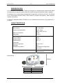
INSTALLATION MANUAL
V 1.3EN
ELECTRIC HEATER
BLEU TITANE®
RTI-EZ
INSTALLATION MANUAL
CCEI
V1.3EN
BLEU TITANE RTI-EZ
p2
INSTALLATION MANUAL
V1.3EN
BLEU TITANE RTI-EZ
SOMMAIRE
PRESENTATION
4
SPECIFICATIONS
4
INSTALLATION
5
Hydraulic connection
5
Electrical connection
5
PRINCIPLE OF OPERATIONS
6
Regulation
6
Time clock setting
6
OPERATION AND MAINTENANCE OF THE HEATER
7
WINTERAGE MANAGEMENT
7
CCEI
p3
INSTALLATION MANUAL
V1.3EN
BLEU TITANE RTI-EZ
PRESENTATION
The electric heaters BLEU TITANE are built with TITANIUM heating body for total
resistance to corrosion. The electric heaters must always be installed on the tubing
before all kind of water treatment devices.
The RTi-EZ range is available in 3, 6 ou 9 kW.
SPECIFICATIONS
Dimensions
Cf. below
230V / 50Hz
400V /50Hz (3F+N)
IP-44
Clase II
Power supply
Protection index
Insolation
Hydraulics
Maximum pressure
Max. Flow
Min. Flow
2 Bar
20m3/ h
5 m3 / h
Thermostat
Regulation scale
Hysteresis
High Temperature Limit
from 20 to 40°C
2°C
60°C max.
Reductions 63/50 (x2)
Manual
Accessories provided
Dimensions :
300mm
L
P
3kW
6kW
9kW
CCEI
L (mm)
425
425
625
p4
INSTALLATION MANUAL
V1.3EN
BLEU TITANE RTI-EZ
INSTALLATION
The heater can be connected directly to pipes with diameter 50 mm or 63 mm.
To use our equipment in the best conditions, we recommend observing the following
parameters in the case of a water treatment with chlorine:
• pH between 6.9 and 7.5.
• Chlorine free active between 0.4 and 1.4 mg / l.
In the case of other type of water treatment, the installer has to check compatibility
with our equipment.
Hydraulic connection
The heater must be installed before any water treatment device. It is strongly
recommended to keep the pipelines of the heater filled with water. After
stopping the pump, the heater must not be emptied by gravity.
The heater can be inserted into a pipe of diameter 63 mm or 50 mm. In 50mm case,
the two adaptor provided must be affixed to both ends of the heater. No additional
piece of PVC is required.
All heaters are supplied with a flow switch. From factory, the heater is configured to
operate with water moving from left to right. (See diagram below).
Flow direction
It is possible to reverse the direction of flow of water by turning the flow switch:
- Switch the filtration pump off and ensure that the heater is not under pressure.
- Unscrew the flow switch. Turn the flow switch 180 degrees. (Do not remove
the gasket that is under the cap). Screw the flow switch.
- Switch on the filtration pump to check that there is no leakage.
- Close the heater and check that the heater stops immediately when the filter
pump is off.
Electrical connection
The heater must be powered from a line protected by a 30 mA differential device
(GFCI). The power supply cable must have a section adapted to the power of the
heater. The appliance must be correctly grounded.
To achieve the electrical connection of the heater, unscrew the 4 screws at the back
of the box (do not touch the screws are on the front of the box). After unscrewing the
4 screws from the rear, you must connect the wires according to one of two examples
given below (single or three phase).
Replace the housing by screwing the four screws from the back of the box.
The table below shows cable section to be used according to the power of the
heater. The cable section must adjusted according to the length of cables.
CCEI
p5
INSTALLATION MANUAL
V1.3EN
POWER
1~ current
3 kW
14 A
6 kW
27 A
9 kW
40 A
For cable length of 50 m max
BLEU TITANE RTI-EZ
3~ current
5A
9A
13 A
1~ cable
4mm²
6mm²
6mm²
3~ cable
2.5mm²
2.5mm²
4mm²
All versions of our electric heaters can be powered in single or three-phase. Both
types of electrical power are presented below. In single phase, bridges must be done
on the terminals with wire jumpers provided.
A circuit diagram is presented in the appendix of this manual.
3 phase
Single phase
* Fils de jonction
A B
Filtration
remote
control
T C N 1
2 3
Neutral
Earth
Phase
POWER SUPPLY
CABLE
A B
Filtration
remote
control
T C N 1 2 3
Neutral
Earth
Phases 1,
2&3
POWER SUPPLY
CABLE
Terminals A and B are used to control the heater from a control panel. If the remote
control is not used, A and B must be bridged.
PRINCIPLE OF OPERATIONS
Regulation
The thermostat controls the heating temperature. The setting value may vary
between 20 and 40 ° C.
Time clock setting
The time clock is useful to limit the heating period in a given time slot of the day .
(i.e. between 14h and 18h).
Indeed, the heat loss of the pool decreases when the water temperature drops. It is
interesting to let the water temperature drop during the non-use (eg at night) and to
anticipate a time of warming-up before the use phase.
The clock allows such a division of heating time and thus save power
consumption. The use of the clock depends on the needs of everyone; it must be
programmed according to individual needs.
CCEI
p6
INSTALLATION MANUAL
V1.3EN
BLEU TITANE RTI-EZ
OPERATION AND MAINTENANCE OF THE HEATER
After the installation of the heater, it is imperative to verify that no leaks exist.
Installer must also ensure that connections of cables are correct (loose cable will
cause heating of the junction).
Before starting the heater, one must ensure that the pipe of the heater is full of water:
Do not put the heater on when it may contain ice. Similarly, we must ensure that the
circuit does not contain air.
Before the first start
- Ensure that the heater starts when increasing the set temperature (beyond the
current temperature) and that water flows through the heater. The green light
should illuminate.
- Ensure that the heater stops when stopping filtration.
- Replace the filter on and make sure that the heater stops when you decrease
the set temperature.
WINTERAGE MANAGEMENT
During the winter, switch off the heater and to drain the heater pipe.
At the restart, check the electric connections, tighten the pipe unions and the flow
switch screw.
CCEI
p7
INSTALLATION MANUAL
V1.3EN
BLEU TITANE RTI-EZ
RTi-EZ
Date de vente :....................................................................................
Puissance : .........................................................................................
N° de lot :: ...........................................................................................
Déclaration
CCEI SA (FR 1507 073 804 973) testifies that pool heater RTi-EZ
complies to European Directives requirements 2006/95/CE and
2004/108/CEE
Emmanuel Baret
Marseille, le 28/02/2010
Cachet du distributeur
CCEI
p8
MANUAL TECNICO
V 1.3E
CALENTADOR ELECTRICO
BLEU TITANE®
RTI-EZ
CCEI
p1
MANUAL TECNICO
V1.3E
BLEU TITANE RTI-EZ
RESUMEN
PRESENTACIÓN ....................................................................................................... 3
CARACTERÍSTICAS ................................................................................................. 3
INSTALACIÓN ........................................................................................................... 4
CONEXIÓN HIDRÁULICA ......................................................................................... 4
Dirección del flujo de agua....................................................................................................4
CONEXION ELECTRICA ........................................................................................... 4
FUNCIONAMIENTO................................................................................................... 5
LANZAMIENTO, MANTENIMIENTO DEL CALENTADOR ....................................... 6
INVERNACIÓN .......................................................................................................... 6
CCEI
p2
MANUAL TECNICO
V1.3E
BLEU TITANE RTI-EZ
PRESENTACIÓN
Los calentadores eléctricos Bleu Titane se entregan con resistencias de inmersión de titanio
que garantizan resistencia óptima contra la corrosión de agua de piscina (dulce o salada).
Se equipan de un temporizador permitiendo la regulación económica del calor. La eficacia
de los calentadores eléctricos Bleu Titane ofrece la manera más rápida y más simple de
calentar una piscina.
La gama de calentador BLEU TITANE con una resistencia única permite a los poderes de 3,
6 o 9 kW
CARACTERÍSTICAS
Generales
Dimensiones
Cf. más abajo
Indice de Protección
Aislamiento
230V / 50Hz
400V /50Hz (3F+N)
IP-44
Clase II
Circuito Hydráulico
Presión máxima
Caudal máximo
Caudal minimo
2 Bar
20m3 / h
5 m3 / h
Tensión de alimentación
Termóstato
Escala de regulación
Histéresis
Temperatura maxima
de 20 a 40°C
2°C
Termostato de seguridad
60°C max.
Accesorios entregados
Reducciones 63/50 (x2)
Manual técnico
Dimensiones :
300mm
L
P
3kW
6kW
9kW
CCEI
L (mm)
425
425
625
p3
MANUAL TECNICO
V1.3E
BLEU TITANE RTI-EZ
INSTALACIÓN
El calentador se puede conectar directamente a la tubería de la piscina en diámetro de 50
mm o 63 mm. Para utilizar nuestros calentadores en las mejores circunstancias, es
aconsejable respetar los siguientes parámetros en el caso de un tratamiento de agua con
cloro:
• pH entre 6,9 y 7,5.
• Cloro activo entre 0,4 y 1,4 mg / l.
En el caso de un tratamiento de agua diferentes, el instalador se asegurará la compatibilidad
con nuestros equipos.
CONEXIÓN HIDRÁULICA
El calentador será instalado obligatorio antes de cualquier dispositivo eléctrico del
tratamiento de aguas. Se aconseja fuertemente mantener el calentador cargado.
Después de la parada de la bomba, el calefactor no debe ser vaciado por gravedad
El calentador puede ser insertado en un tubo de diámetro nominal de 63 mm o 50 mm. En
este último caso, los dos reductores siempre se colocarán en ambos extremos de la
calefacción. No necesita extra piezas de PVC.
Dirección del flujo de agua
Todos los calentadores se suministran con un interruptor de flujo. Inicialmente, el calentador
está diseñado para funcionar con el agua se mueve de izquierda a derecha. (Vea el
diagrama abajo).
Dirección del flujo
Sin embargo, es posible invertir el flujo de agua por el cambio de dirección del interruptor de
flujo:
• Garantizar que la presión del agua no está en el calentador.desenroscar la salida del
sensor.
• Gire el interruptor de flujo de 180 °. (no quitar la placa de sello se encuentra bajo la
tapa).
• Reemplace el sensor de velocidad. circular el agua a través del calentador para
asegurarse de que no haya fugas en el flujo del detector.
• Cerrar la estufa y verificar su funcionamiento: en particular, comprobar que el
calentador se detiene instantáneamente cuando el filtro de la bomba está apagada.
CONEXIÓN ELÉCTRICA
El calentador se debe alimentar de una línea protegida por un dispositivo diferencial de
30mA y por una protección apropiada de la sobrecarga.
La protección debe corresponder la corriente absorbida por el calentador.
El calentador se debe conectar con la tierra.
CCEI
p4
MANUAL TECNICO
V1.3E
BLEU TITANE RTI-EZ
Para lograr la conexión eléctrica del calentador, desenroscar los 4 tornillos en la parte
posterior de la caja (no toque los tornillos situados en la parte frontal de la caja). Después de
desatornillar los 4 tornillos de la parte trasera, hay que conectar los cables de uno de los dos
siguientes ejemplos (monofásica o trifásica) que figura a continuación.
Monofásico
Trifásico
Regeltas de unión
A B
T C1 C2 N 1
neutro
2
3
A B
30
fase
Mando a
distancia
Mando a
distancia
T C N 1
CABLE DE
ALIMENTACIÓN
3
neutro
tierra
tierra
2
fases 1, 2
y3
CABLE DE
ALIMENTACIÓN
Todas las versiones de calentadores eléctricos BLEU TITANE se pueden alimentar de la
corriente monofásica o trifásica.
Los dos tipos de conexión eléctrica se presentan abajo. Un diagrama eléctrico se presenta
en apéndice de este manual.
Las terminales A y B permiten el mando a distancia. El usuario puede, si lo desea,
desconecte el puente y conectar las dos terminales en un contacto seco de otra caja. Ambos
terminales por lo tanto puede esclavizar el calentador a otro cuadro eléctrico.
Proponemos abajo como indicación las secciones de cables de ser utilizado alimentar el
calentador. Estas secciones se deben controlar y adaptar en caso de necesidad según las
longitudes de cables.
PUISSANCE
3 kW
6 kW
9 kW
Intensité mono
14 A
27 A
40 A
Intensité TRI
5A
9A
13 A
Câble mono
3G4²
3G6²
3G6²
Câble TRI
5G2.5²
5G2.5²
5G4²
FUNCIONAMIENTO
Reglamento
El termostato de control permite establecer el punto de control de calefacción. Este punto
puede variar entre 20 y 40 ° C.
Ajuste del reloj
Durante la fase de elevación de la temperatura del agua, es altamente recomendable que
use el calentador en el modo manual (bypass del reloj).
CCEI
p5
MANUAL TECNICO
V1.3E
BLEU TITANE RTI-EZ
Sin embargo, el reloj es muy útil cuando el aumento de la temperatura de la piscina es finita
y que el calentador se utiliza solamente para mantener la temperatura del agua durante un
período determinado del día (ejemplo: entre 14h y 18h).
De hecho, las pérdidas térmicas de la piscina disminuye cuando la temperatura del agua
hacia abajo. Es interesante para que la caída de la temperatura del agua cuando la piscina
no se utiliza (por ejemplo, en la noche) y predecir el tiempo necesario para calentar antes de
usar. El reloj permite este tipo de programación de tiempo de calentamiento y por lo tanto
ahorrar tiempo de calentamiento. El uso del reloj depende de las necesidades individuales,
debe ser programado en consecuencia.
LANZAMIENTO, MANTENIMIENTO DEL CALENTADOR
Después del ensamblaje del calentador, es imprescindible controlar que existe ningún
escape. También se necesita controlar el ajuste correcto de los cables (un cable malamente
apretado causará una calefacción de la ensambladura). Antes del primer uso, hay que ser
seguro de que el sistema hydráulico del calentador es lleno de agua y que el circuito no
contiene aire.
A la hora del primer lanzamiento:
¾ Controle que el calentador comienza cuando Ud fija el termóstato a un valor sobre
la temperatura real y que el agua circula en el calentador. El indicador verde debe
encenderse
¾ Controle que el calentador para cuando Ud corta la filtración.
¾ Relanze la filtración y cerciórese de que el calentador para cuando se disminuye
la configuración de la temperatura.
INVERNACIÓN
Durante el invierno, es aconsejable cambiar a "off" de protección aguas
arriba de la estufa y también puestos en el "0" interruptores permiten el
cambio de resistencias 1 y 2.
También se recomienda de drenar el circuito del calentador. Nuestros calentadores
están equipados con un tapón de desagüe.
En la entrega en servicio, es necesario comprobar la sujeción de las conexiones
uniones y del detector de producción.
CCEI
p6
MANUAL TECNICO
V1.3E
BLEU TITANE RTI-EZ
RTi-EZ
Fecha de la venta: ..............................................................................
Potencia: .............................................................................................
N° de lote: ...........................................................................................
Declaración
La sociedad CCEI SA (FR 1507 073 804 973) declara que el
calentador RTi-EZ cumple las exigencias de seguridad y
compatibilidad electromagnética de las directivas europeas
2006/95/CE et 2004/108/CEE
Emmanuel Baret
Marsella, a 28/02/2005
Sello del distribuidor
CCEI
p7