1
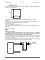
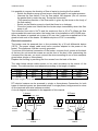
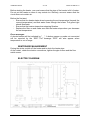
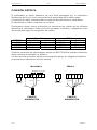
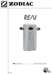
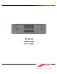
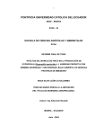
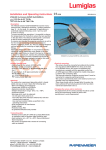
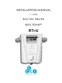
INSTALLATION MANUAL
V 1.0 EN
ELECTRIC HEATER
BLEU TITANE®
RTI-U
Installation Manual
v1.0 EN
BLEU TITANE RTi-U
SOMMAIRE
PRESENTATION
3
SPECIFICATIONS
3
INSTALLATION
4
Hydraulic connection
4
Electrical connection
5
PRINCIPLE OF OPERATIONS
6
Regulation
6
Temperature setting
6
Time clock setting
6
OPERATION AND MAINTENANCE OF THE HEATER
6
WINTERAGE MANAGEMENT
7
ERROR MESSAGES
7
ELECTRIC DIAGRAM
7
CCEI
p2
Installation Manual
v1.0 EN
BLEU TITANE RTi-U
PRESENTATION
The electric heaters BLEU TITANE are built with TITANIUM heating body for total
resistance to corrosion. The electric heaters must always be installed on the tubing
before all kind of water treatment devices.
The RTi-EZ range is available in 12, 15 or 18 kW.
SPECIFICATIONS
Dimensions
Power supply
Protection index
Insolation
Cf. below
230V / 50Hz
400V /50Hz (3F+N)
IP-44
Clase I
Hydraulics
Maximum pressure
Max. Flow
Min. Flow
Thermostat
Regulation scale
Hysteresis
High Temperature Limit
Accessories provided
Hauteur
120 mm
2 Bar
20m3/ h
5 m3 / h
from 10 to 40°C
1°C (adjustable)
60°C max.
Reductions 63/50 (x2)
Installation Manual
530 mm
565 mm pour D=63 mm
580 mm pour D=50 mm
CCEI
p3
Installation Manual
v1.0 EN
BLEU TITANE RTi-U
INSTALLATION
The heater has to be fixed to the wall. Use the 4 screws to fasten the metal plate as
shown on the diagram below.
460 mm
420 mm
The heater can be connected directly the pool pipeline with 50 mm or 63 mm
diameter.
To use the heater in the best conditions, it is advisable to observe the following
parameters in the case of a water treatment with chlorine :
pH between 6.9 and 7.5
Free chlorine between 0.4 and 1.4 mg / L
In the case of different water treatment, the installer will ensure compatibility with the
equipment.
Note : 1 mg/L = 1 ppm
Hydraulic connection
The heater must be installed before any water treatment device. It is strongly
recommended to keep the pipelines of the heater filled with water. After
stopping the pump, the heater must not be emptied by gravity.
The heater can be inserted into a pipe of diameter 63 mm or 50 mm. In 50mm case,
the two adaptor provided must be affixed to both ends of the heater. No additional
piece of PVC is required.
The heater is equipped with a flow switch. From factory, the heater is configured to
operate with water moving from left to right. (See diagram below).
To the pool
To any water
treatment device
FILTER
CCEI
p4
Installation Manual
v1.0 EN
BLEU TITANE RTi-U
It is possible to reverse the direction of flow of water by turning the flow switch:
- Switch the filtration pump off and ensure that the heater is not under pressure.
- Unscrew the flow switch. Turn the flow switch 180 degrees. (Do not remove
the gasket that is under the cap). Screw the flow switch.
(The operative direction of the flow-switch is given by the arrow on the body of
the flow-switch)
- Switch on the filtration pump to check that there is no leakage.
- Close the heater and check that the heater stops immediately when the filter
pump is off.
The minimum flow rate is 5m3/h and the maximum flow is 20 m3/h. When the flow
rate exceeds this maximum value, the heater has to be installed on a BY-PASS pipe.
When the heater is inserted into a pipe of 50 mm, the 2 reduction supplied has to be
glued to both ends of the heater. No additional piece of PVC is necessary.
Electrical connection
The heater must be powered from a line protected by a 30 mA differential device
(GFCI). The power supply cable must have a section adapted to the power of the
heater. The appliance must be correctly grounded.
To achieve the electrical connection of the heater, unscrew the 4 screws at the back
of the box (do not touch the screws are on the front of the box). After unscrewing the
4 screws from the rear, you must connect the wires according to one of two examples
given below (single or three phase).
Replace the housing by screwing the four screws from the back of the box.
The table below shows cable section to be used according to the power of the
heater. The cable section must adjusted according to the length of cables.
POWER
1~ current
12 kW
53 A
15 kW
65 A
9 kW
80 A
For cable length of 50 m max
3~ current
18 A
22 A
27 A
1~ cable
10mm²
10mm²
16mm²
3~ cable
4mm²
4mm²²
6mm²
RTi electric heaters can be powered in single or three-phase. Connection for both
types of electrical power are presented below. In single phase, bridges must be done
on the terminals with wire jumpers provided.
A circuit diagram is presented in the appendix of this manual.
3 Phase
1 phase
Junction wires
A B
Filtration
remote
control
T C1 C2 N 1
Neutral
2 3
Phase
Filtration
remote contro
Earth
POWER SUPPLY
CABLE
CCEI
A B
T C1 C2 N 1 2
3
Neutral
Earth
Phases
1, 2 & 3
POWER SUPPLY
CABLE
p5
Installation Manual
v1.0 EN
BLEU TITANE RTi-U
Terminals A and B are used to control the heater from a control panel. If the remote
control is not used, A and B must be bridged.
PRINCIPLE OF OPERATIONS
Regulation
The thermostat controls the heating temperature. The setting value may vary
between 10 and 40 ° C.
In addition, to adapt the heating power, switches can select the heating resistor to be
in operation.
Note :
- In the case of a 15 kW heater, resistance #1 is a 6kW and #2 is
9kW.
- The thermostat is factory preset. The only value available to the
user is the desired temperature which is limited at 40 °C.
Temperature setting
- Press the SET button for 3 seconds maximum
- Press ¥ (up) to increase the temperature.
- Press ¦ (down) to decrease the temperature.
- Confirm setting by waiting a few seconds to return to the initial display.
When the output is active, the LED "OUT" lights. This means that the heater is in
heating demand.
Note : The differential set point has been factory preset at -5 ° C. This means that
when for example the temperature is set to 30°C , the heater will heat water to 30°C
then stop and resume heating when the water drops to 25°C.
Time clock setting
The time clock is useful to limit the heating period in a given time slot of the day .
(i.e. between 14h and 18h).
Indeed, the heat loss of the pool decreases when the water temperature drops. It is
interesting to let the water temperature drop during the non-use (eg at night) and to
anticipate a time of warming-up before the use phase.
The clock allows such a division of heating time and thus save power
consumption. The use of the clock depends on the needs of everyone; it must be
programmed according to individual needs.
OPERATION AND MAINTENANCE OF THE HEATER
After the installation of the heater, it is imperative to verify that no leaks exist.
Installer must also ensure that connections of cables are correct (loose cable will
cause heating of the junction).
CCEI
p6
Installation Manual
v1.0 EN
BLEU TITANE RTi-U
Before starting the heater, one must ensure that the pipe of the heater is full of water:
Do not put the heater on when it may contain ice. Similarly, we must ensure that the
circuit does not contain air.
Before the first start
- Ensure that the heater starts when increasing the set temperature (beyond the
current temperature) and that water flows through the heater. The green light
should illuminate.
- Ensure that the heater stops when stopping filtration.
- Replace the filter on and make sure that the heater stops when you decrease
the set temperature.
Error messages
A shorted sensor will be indicated by "_ _". A broken sensor or probe not connected
will be reported by the “EEE”. The message "EEE" will also appear when
temperature is out of range.
WINTERAGE MANAGEMENT
During the winter, switch off the heater and to drain the heater pipe.
At the restart, check the electric connections, tighten the pipe unions and the flow
switch screw.
ELECTRIC DIAGRAM
CCEI
p7
Installation Manual
v1.0 EN
BLEU TITANE RTi-U
RTi-U
Date de vente :....................................................................................
Puissance : .........................................................................................
N° de lot :: ...........................................................................................
Déclaration
CCEI SA (FR 1507 073 804 973) testifies that pool heater RTi-U
complies to European Directives requirements 2006/95/CE and
2004/108/CEE
Emmanuel Baret
Marseille, le 28/02/2010
Cachet du distributeur
CCEI
p8
CCEI S.A.
Ed. 2005
MANUAL TÉCNICO
V1.0E
CALENTADORES ELÉCTRICOS
BLEU TITANE®
RTi-U
CCEI
página 1
MANUAL TÉCNICO
V1.0E
BLEU TITANE RTI-U
RESUMEN
RESUMEN
2
CARACTERÍSTICAS
3
PRESENTACIÓN
4
INSTALACIÓN
4
CONEXIÓN HIDRÁULICA
5
CONEXIÓN ELÉCTRICA
6
FUNCIONAMIENTO
7
a) Regulación
7
b) Ajuste de la temperatura de consigna
7
c) Ajuste del reloj
7
LANZAMIENTO, MANTENIMIENTO DEL CALENTADOR
8
GERENCIA DE LOS DEFECTOS
8
INVERNACIÓN
8
DIAGRAMA ELÉCTRICO
9
CCEI
página 2
MANUAL TÉCNICO
V1.0E
BLEU TITANE RTI-U
CARACTERÍSTICAS
Generales
Dimensiones (an x al x p) en mm
Tensión de alimentación
Indice de Protección
Aislamiento
Cf. más abajo
230V / 50Hz
400V /50Hz (3F+N)
IP-55
Clase II
Circuito Hydráulico
Presión máxima
Caudal máximo
Caudal minimo
Termóstato
Escala de regulación
Resolución
Temperatura maxima
Accesorios entregados
2 Bar
20m3
5 m3 / h
de 10 a 40°C
±1°C
Termostato de seguridad
60°C max.
TE de PVC 63x32x63 con
tapón de vacio.
Reducciones 63/50 (x4)
Manual técnico
530 mm
120 mm
565 mm
CCEI
página 3
MANUAL TÉCNICO
V1.0E
BLEU TITANE RTI-U
PRESENTACIÓN
Los calentadores eléctricos Bleu Titane se entregan con resistencias de
inmersión de titanio que garantizan resistencia óptima contra la corrosión de
agua de piscina (dulce o salada).
Se equipan de un temporizador permitiendo la regulación económica del
calor. La eficacia de los calentadores eléctricos Bleu Titane ofrece la manera
más rápida y más simple de calentar una piscina.
INSTALACIÓN
El calentador se fija en la pared. La fijación es hecha por cuatro tornillos a partir
el platina de fondo del calentador, y según el esquema siguiente:
460
420
El calentador se puede conectar directamente en la línea de la piscina en
diámetro 50 milímetros o 63 milímetros. Para utilizar el producto bajo mejores
condiciones, se aconseja respetar los parámetros siguientes :
En caso de tratamiento del agua con cloro: El pH debe quedarse entre 6,9 y 7,5
y el cloro libre entre 0,4 y 1,4 mg/l.
En el caso de un tratamiento del agua alterna, el installator tendrá que
controlar la compatibilidad con nuestra material.
CCEI
página 4
MANUAL TÉCNICO
V1.0E
BLEU TITANE RTI-U
CONEXIÓN HIDRÁULICA
El calentador será instalado obligatorio antes de cualquier dispositivo eléctrico
del tratamiento de aguas. Se aconseja fuertemente mantener el calentador
cargado según lo mostrado en el diagrama siguiente.
dispositivo eléctrico
del tratamiento de
aguas
FILTRE
El calentador se diseña para la circulación del agua de la tapa al fondo.
El caudal del agua se debe mantener entre 5 m3/h y 20 m3/h. Por otra parte, el
calentador se puede instalar en un tubo de 63 mm o 50 mm de diámetro
nominal. En este último caso, los dos reducciones se deben pegar en los dos
extremos del calentador. No se requiere ninguna pieza adicional de PVC para
la instalación. Proporcionamos a un Te de PVC reducido equipado de un tapón
de desagüe. Esta pieza se debe ensamblar en el tubo según lo mostrado en el
diagrama antedicho.
CCEI
página 5
MANUAL TÉCNICO
V1.0E
BLEU TITANE RTI-U
CONEXIÓN ELÉCTRICA
El calentador se debe alimentar de una línea protegida por un dispositivo
diferencial de 30 mA y por una protección apropiada de la sobrecarga.
La protección debe corresponder la corriente absorbida por el calentador.
El calentador se debe conectar con la tierra.
Proponemos abajo como indicación las secciones de cables de ser utilizado
alimentar el calentador. Estas secciones se deben controlar y adaptar en caso
de necesidad según las longitudes de cables.
Monofásico
Intensidad
Cable
53 A
18 A
65 A
22 A
80 A
27 A
POTENCIA
12 kW
15 kW
18 kW
Trifásico
Intensidad
Cable
3G10²
5G4²
3G10²
5G4²
3G16²
5G6²
Todas las versiones de calentadores electricos BLEU TITANE se pueden alimentar
de la corriente monofásica o trifásica.
Los dos tipos de conexión eléctrica se presentan abajo. Un diagrama eléctrico
se presenta en apéndice de este manual.
Monofásico
Trifásico
Regeltas de unión
A B
T C1 C2 N 1
neutro
Mando a
distancia
fase
tierra
CABLE DE
ALIMENTACIÓN
CCEI
2
3
A B
Mando a
distancia
T C N 1
2
3
neutro
tierra
fases 1, 2
y3
CABLE DE
ALIMENTACIÓN
página 6
MANUAL TÉCNICO
V1.0E
BLEU TITANE RTI-U
FUNCIONAMIENTO
a) Regulación
Para una seguridad óptima, el termóstato de la regulación se sostiene con un
termóstato de seguridad.
El termóstato de seguridad preajustado a 60 °C está con un rearme manual.
Además, para ajustar la potencia de calefacción, dos interruptores puede
seleccionar el número de resistencias a estar en funcionamiento. La posición
manual en la primera posición y el reloj de abajo.
El termostato de reglamento se preestablece completamente en fábrica. El
único valor accesible al usuario es la temperatura de consigna que podrá
fijarse en 40 °C como máximo.
b) Ajuste de la temperatura de consigna
Pulse el botón SET para un máximo de 3 segundos
Prensa ▲ para aumentar la temperatura.
Presione ▼ para disminuir la temperatura.
Validar el ajuste esperar unos segundos para volver a la pantalla inicial.
Cuando la salida está activa, el LED "OUT" ilumina. Esto significa que el
calentador está en calefacción.
Nota :
La histéresis del punto de control ha sido establecida de fábrica a -5°C. Esto
significa que cuando se ajusta la temperatura a 30 ° C, por ejemplo, el
calentador de agua se calentará hasta 30 ° C, y luego detener y reanudar la
calefacción cuando el agua alcanza los 25 ° C.
c) Ajuste del reloj
Durante la fase de subida en temperatura del agua, se aconseja mucho utilizar
el calentador en modo manual (sin reloj). Por el contrario, el reloj encuentra
todo su interés cuando se termina la subida en temperatura de la piscina y que
el calentador sirve solamente para mantener el agua en temperatura durante
una duración fija del día (ejemplo: entre 14h y 18h). En efecto, las pérdidas
térmicas de la piscina disminuyen cuando la temperatura del agua baja. Es
pues interesante dejar recaer la temperatura del agua durante la fase de no
utilización (ejemplo: la noche) y de prever un tiempo necesario de recalentado
antes de la fase de utilización. El reloj permite tal reparto del tiempo de
calefacción y en consecuencia de las economías de tiempo de calefacción.
La utilización del reloj depende de las necesidades de cada uno; ésta debe
pues programarse a individualmente.
CCEI
página 7
MANUAL TÉCNICO
V1.0E
BLEU TITANE RTI-U
LANZAMIENTO, MANTENIMIENTO DEL CALENTADOR
Después del ensamblaje mecánico del calentador, es imprescindible controlar
que existe ningún escape. También se necesita controlar el ajuste correcto de
los cables (un cable malamente apretado causará una calefacción de la
ensambladura). Antes del primer uso, hay que ser seguro de que el sistema
hydráulico del calentador es lleno de agua y que el circuito no contiene aire.
A la hora del primer lanzamiento:
¾ Controle que el calentador comienza cuando Ud fija el termóstato a
un valor sobre la temperatura real y que el agua circula en el
calentador. El indicador verde debe encenderse
¾ Controle que el calentador para cuando Ud corta la filtración.
¾ Relanze la filtración y cerciórese de que el calentador para cuando se
disminuye la configuración de la temperatura.
GERENCIA DE LOS DEFECTOS
El corto circuito sensor de temperatura será indicado por "_". Un sensor roto o
sonda no se conecta por la AEMA. El mensaje "EEE", también aparecerá
cuando hay un exceso en el rango de temperatura.
En el caso que la temperatura excede el límite máximo de 60°C, el termóstato
de seguridad entrará apagado. Este corte para la calefacción
inmediatamente y una restauración manual es necesaria.
La restauración es hecha desatornillando el casquillo en el lado del cuadro y
empujando el botón rojo.
INVERNACIÓN
Durante el invierno, es aconsejable cambiar a "off" de protección aguas arriba
de la estufa y también puestos en el "0" interruptores permiten el cambio de
resistencias 1 y 2.
También se recomienda de drenar el circuito del calentador. Nuestros
calentadores están equipados con un tapón de desagüe.
En la entrega en servicio, es necesario comprobar la sujeción de las
conexiones uniones y del detector de producción.
CCEI
página 8
MANUAL TÉCNICO
V1.0E
BLEU TITANE RTI-L
DIAGRAMA ELÉCTRICO
CCEI
página 9
MANUAL TÉCNICO
BLEU TITANE RTI-U
V1.0E
RTi-U
Fecha de la venta:..............................................................................
Potencia:...............................................................................................
N° de lote: .............................................................................................
Declaración
La sociedad CCEI SA (FR 1507 073 804 973) declara que el
calentador RTi-U cumple las exigencias de seguridad y
compatibilidad electromagnética de las directivas europeas
2006/95/CE et 2004/108/CEE
Emmanuel Baret
Marsella, a 28/02/2005
Sello del distribuidor
CCEI
página 10