1
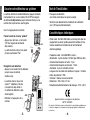
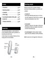
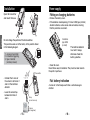
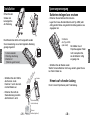
DTX
France :
Détecteur technique
universel
DELTA DORE TALCO - Bonnemain - 35270 COMBOURG
E-mail : [email protected]
pro.deltadore.com
Detector técnico
universal
Universal technical
detector
España :
DELTA DORE ELECTRÓNICA, S.A
C/ Antoni Borja, 13
Semi-sótano, local 1 y 2 - 08191 Rubí (Barcelona)
Tlf. : 93 699 65 53 - Fax. : 93 588 19 66
E-mail : [email protected]
www.deltadore.es
Neue Adresse ab Frühjahr 2007
D - 76829 Landau, Fichtenstrasse 38a
2701404 Rév.1
Deutschland :
DELTA DORE Schlüter GmbH
Am Kleinwald 13 - 76863 HERXHEIM
Telefon 07276 - 96690 Telefax 07276 - 502120
E-mail : [email protected]
Technischer
Funk-Universal-Sender
Notice d'installation et d'utilisation
Manual de instalación y de utilización
Installation and User Guide
Installations- und Bedienungsanleitung
Principe de fonctionnement
1. Présentation . . . . . . . . . . . . . . . . . . . . . . . . . .p 1
2. Principe de fonctionnement . . . . . . . . . . . . . . .p 2
Quel que soit l’état du système (En ou Hors surveillance),
lors de la détection d’un défaut, la signalisation est la
suivante :
3. Installation . . . . . . . . . . . . . . . . . . . . . . . . . .p 3
4. Alimentation . . . . . . . . . . . . . . . . . . . . . . . . .p 4
5. Associer votre détecteur au système . . . . . . . .p 5
6. Test de l’installation . . . . . . . . . . . . . . . . . . . .p 6
7. Caractéristiques techniques . . . . . . . . . . . . . . .p 6
- Sur une centrale :
Emission des bips de mise en garde (bip, bip, bip... pendant
45 sec. Ce cycle est répété jusqu’à 4 fois si le défaut est
permanent.
Elle signalera le défaut par son voyant 1 “alarme”.
- Sur un transmetteur :
Déclenchement d’un cycle d’appel. Il indiquera “défaut technique”. Depuis votre téléphone, en appuyant sur la touche
étoile, le transmetteur diffusera son message personnalisé.
Présentation
Le détecteur technique universel est un émetteur radio auquel
doit être raccordé un capteur technique (détecteur de gaz, ...)
intégrant une sortie contact sec.
Il signale à la centrale d’alarme chaque détection de défaut
par un message de type “alarme technique”.
Bouton test
- Sur un clavier info commande, l’indication “détecteur
technique” apparaît à l’écran, puis son identité
(personnalisable).
Nota : Il n’y a pas de déclenchement de la sirène du système
dans le cas d’une alarme technique.
Capteur
(non fourni)
Vis de
fermeture
-1-
-2-
Français
Français
Sommaire
Ouvrir l’émetteur
et fixer le socle.
- Enlever la languette de protection des piles.
- En cas de remplacement, placer 2 piles alcalines type LR03
(ou AAA) neuves, de même provenance et de même date
en respectant la polarité indiquée.
3
2
1
2 piles
type LR03
(ou AAA)
Ne pas modifier la position des micro-commutateurs.
Ils ont été réglés en usine dans la position indiquée
sur le schéma suivant.
Le détecteur technique
doit émettre 2 bips,
sinon vérifier la polarité
des piles.
ON
1 : émetteur universel
2 : déclenchement immédiat
3 : type de contact
(normalement fermé)
n
1 2 3
- Raccorder les 2 fils du
capteur aux bornes 1 et 2
du détecteur technique
Emetteur
Signalisation de piles usées
Par une série de 3 bips courts, à chaque émission d’un
message radio
1 2 3
- Laisser le strap câblé
entre les bornes 2 et 3.
- Refermer le capot.
Ne pas jeter les piles usagées, celles-ci seront récupérées
sur le lieu d’achat.
Strap
(ne pas enlever)
Capteur
(non fourni)
-3-
-4-
Français
Alimentation
Mise en place ou changement des piles
1A
2- la
C rm
3- om e
AP m
u
Français
Installation
Test de l’installation
La centrale doit être en mode Maintenance (appuyer simultanément pendant 5 sec. sur les touches ON et OFF d’un organe
de commande déjà reconnu jusqu’à l’émission d’un bip sur la
centrale. Son voyant en face avant clignote.
Ouvrir la trappe piles de la centrale.
1234
567
BiiiP
5 sec.
Enregistrer votre détecteur
- Appuyer sur le bouton test du détecteur,
jusqu’à ce que la centrale
émette un bip.
1234
567
- Refermer la trappe piles de la
centrale.
BiiiP
- Portée radio : De 200 à 300 mètres en champ libre selon les
équipements associés (portée pouvant être altérée en fonction des conditions d'installation et de l'environnement
électromagnétique)
- Fréquences radio : 434 et 868 MHz, classe I
- Alimentation : 2 piles alcalines 1,5 Volts type LR03 (ou AAA)
- Consommation moyenne en veille : 12 µA
- Consommation moyenne en émission : 15 mA
- Autonomie : 3 ans en utilisation normale
- Longueur maxi du câble entre émetteur et capteur : 3 mètres
- Indice de protection : IP30
- Utilisation : intérieur sec exclusivement
- Dimensions : 102 x 32,5 x 31 mm
- Température de fonctionnement et de stockage : -10°C / +55°C
BiiiP
1
1
alarme
2
autoprotection
3
pile
4
supervision
5
issue ouverte
effacer
-5-
• Vérifier le bon déroulement du traitement de la détection
(voir § Principe de fonctionnement)
Caractéristiques techniques
Passer la centrale en menu “produit”
- Appuyer plus de 5 sec. sur la touche
“ON” d’un organe de commande
déjà reconnu,
La centrale émet un bip et son voyant
en face avant devient “fixe”.
- La centrale émet un bip et son
voyant “1” (détecteur) s’allume.
(ce voyant est déjà allumé si
un élément de détection a déjà
été enregistré)
• Provoquer une détection
(voir notice constructeur du capteur associé)
tester
Appareil conforme aux exigences des directives
R&TTE 1999/5/CE
En raison de l’évolution des normes et du matériel, les caractéristiques indiquées par
le texte et les images de ce document ne nous engagent qu’après confirmation par
nos services.
-6-
Français
Français
Associer votre détecteur au système
Principio de funcionamiento
1. Presentación . . . . . . . . . . . . . . . . . . . . . . .pág. 7
Español
2. Principio de funcionamiento . . . . . . . . . . . .pág. 8
3. Instalación . . . . . . . . . . . . . . . . . . . . . . . . .pág. 9
4. Alimentación . . . . . . . . . . . . . . . . . . . . . .pág. 10
5. Asociar su detector al sistema . . . . . . . . . .pág. 11
6. Prueba de la instalación . . . . . . . . . . . . . .pág. 12
7. Características técnicas . . . . . . . . . . . . . . .pág. 12
Presentación
El detector técnico universal es un emisor radio al que debe
conectarse un sensor técnico (detector de gas, etc.) con una
salida contacto seco.
Informa la central de alarma cada vez que detecta un fallo
mediante un mensaje de tipo “alarma técnica”.
Botón prueba
Independientemente del estado del sistema (en o sin vigilancia),
durante la detección de un fallo, la señal es la siguiente:
- En una central:
Emisión de sonidos de advertencia (bip, bip, bip...) durante
45 seg. Este ciclo se repite hasta 4 veces si el fallo es
permanente.
Informará del fallo a través del testigo 1 “alarma”.
- En un transmisor:
Activación de un ciclo de llamada. Indicará “detector”.
El transmisor comunicará su mensaje personalizado pulsando
la tecla asterisco de su teléfono.
- En un teclado infomando, el mensaje “detector técnico”
se visualiza en la pantalla y, a continuación, su identidad
(personalizable).
Nota: la sirena del sistema no se activa en caso de alarma
técnica.
Sensor
(no suministrado)
Tornillo
de cierre
-7-
-8-
Español
Índice
Alimentación
Colocar o cambiar las pilas
- Sacar la lengüeta de protección de las pilas.
- En caso de sustitución, colocar 2 pilas alcalinas tipo LR03
(o AAA) nuevas, de la misma procedencia y con la misma
fecha, respetando la polaridad indicada.
3
2
1
2 pilas
tipo LR03
(o AAA)
No modificar la posición de los microconmutadores.
En el esquema siguiente se indica la posición de los
ajustes de fábrica:
ON
1 : emisor universal
2 : activación inmediata
3 : tipo de contacto
(normalmente cerrado)
- Conectar los 2 cables del
sensor a los bornes 1 y 2
del detector técnico.
1 2 3
1A
2- la
C rm
3- om a
AP ú
n
Español
Abrir el emisor y
fijar el zócalo.
Emisor
El detector técnico debe
emitir 2 señales sonoras
(“bip”), sino comprobar la
polaridad de las pilas.
- Colocar la tapa.
No tirar las pilas usadas. Éstas serán recuperadas en el lugar
de compra.
Señal de pilas usadas
Mediante una serie de 3 señales cortas (“pip”), cada vez que
se emite un mensaje radio.
1 2 3
- Dejar la barrita cableada
entre los bornes 2 y 3.
Barrita
(no extraer)
Sensor
(no suministrado)
-9-
- 10 -
Español
Instalación
Prueba de instalación
La central debe estar en modo Mantenimiento (pulsar simultáneamente durante 5 seg. las teclas ON y OFF de un instrumento
de mando ya reconocido hasta que la central emita una señal
sonora (“bip”). El testigo de la parte frontal de ésta parpadea.
• Provocar una detección
(véase manual del fabricante del sensor asociado).
• Comprobar el buen desarrollo del tratamiento de la detección
(véase § Principio de funcionamiento).
Abrir el compartimento de las pilas
de la central.
Características técnicas
1234
567
Seleccionar el menú “producto” en la
central
- Pulsar más de 5 seg. la tecla “ON”
de un instrumento de mando ya
reconocido.
La central emite un “bip” y el testigo
de la parte frontal de ésta pasa a ser fijo.
- La central emite un “bip” y el
testigo 1 (detector) de ésta se
enciende (este testigo ya está
encendido si un elemento de
detección ha sido registrado).
- Cerrar el compartimento de
las pilas de la central.
- 11 -
1234
567
Registrar su detector
- Pulsar el botón prueba del
detector hasta que la central
emita un “bip”.
Bip
5 seg.
Bip
- Alcance radio: De 200 a 300 metros en campo libre según
los equipos asociados (el alcance puede verse alterado en
función de las condiciones de instalación y del entorno
electromagnético).
- Radiofrecuencias: 434 y 868 MHz, clase I
- Alimentación: 2 pilas alcalinas 1,5 V tipo LR03 (o AAA)
- Consumo medio en modo “standby”: 12 µA
- Consumo medio en modo emisión: 15 mA
- Autonomía: 3 años en utilización normal
- Longitud máxima del cable entre el emisor y el sensor: 3 metros
- Índice de protección: IP30
- Utilización: interior seco exclusivamente
- Dimensiones: 102 x 32,5 x 31 mm
- Temperatura de funcionamiento y almacenaje: -10°C / +55°C
Bip
1
1
alarma
2
autoprotección
3
pila
4
supervisión
5
salida abierta
borrar
probar
Aparato conforme a las exigencias de las directivas
R&TTE 1999/5/CE.
Debido a la evolución de las normas y del material, las características indicadas por
el texto y las imágenes de este documento sólo nos comprometen después de
haber sido confirmados por nuestros servicios.
- 12 -
Español
Español
Asociar el detector al sistema
Contents
Operating principle
1. Presentation . . . . . . . . . . . . . . . . . . . . . . .pg. 13
2. Operating principle . . . . . . . . . . . . . . . . . .pg. 14
Whatever the system status (surveillance activated or
deactivated), the following indications are used when a fault
is detected:
4. Power supply . . . . . . . . . . . . . . . . . . . . . . .pg. 16
English
5. Associating the detector with the system . .pg. 17
6. System test . . . . . . . . . . . . . . . . . . . . . . . .pg. 18
7. Technical characteristics
- On control unit:
Warning beeps emitted (beep, beep, beep, etc. for 45 sec.).
This cycle is repeated up to 4 times if the fault is permanent.
The fault will be indicated by the “alarm” LED 1.
. . . . . . . . . . . . . .pg. 18
- On a transmitter:
Triggering of a ringing cycle. It will indicate a “technical fault”.
By pressing the star key on your telephone, the transmitter
will send its customized message.
Presentation
The universal technical detector is a radio transmitter that
must be connected to a technical sensor (gas detector, etc.)
incorporating a dry contact output.
It informs the alarm unit by sending a “technical alarm” type
message each time a fault is detected.
Test button
- On a control keypad, the “technical detector” indication
appears on the screen, followed by its identity (customizable).
Note: No system siren will be triggered for a technical alarm.
Sensor
(not supplied)
Closing
screw
- 13 -
- 14 -
English
3. Installation . . . . . . . . . . . . . . . . . . . . . . . .pg. 15
Installation
Power supply
Fitting or changing batteries
Open the transmitter
and mount the base.
- Remove the battery cover.
- If the batteries need replacing, fit 2 new LR03 type (or AAA)
alkaline batteries, same source and same date, ensuring
that the polarities are correct.
3
2
2 batteries
type LR03
(or AAA)
The technical detector
must emit 2 beeps,
otherwise check the
battery polarities.
ON
1 : universal transmitter
2 : immediate triggering
3 : type of contact
(normally closed)
n
1 2 3
- Connect the 2 wires of
the sensor to terminals 1
and 2 of the technical
detector
Transmitter
Flat battery indication
A series of 3 short beeps each time a radio message is
emitted.
1 2 3
- Leave the wired strap
between terminals 2
and 3.
- Close the cover.
Never throw away flat batteries. They must be taken back to
the point of purchase.
Strap
(do not remove)
Sensor
(not supplied)
- 15 -
- 16 -
English
Do not change the position of the microswitches.
The positions were set at the factory in the position shown
in the following diagram.
1A
2- la
C rm
3- om
AP m
o
English
1
Associating the detector with the system
The control unit must be in Maintenance mode (press the ON
and OFF buttons simultaneously for 5 seconds on an already
recognized control unit until the control unit emits a beep).
The front panel LED flashes.
• Trigger a detection action
(see manufacturer's instructions for the associated sensor)
• Check that the detection occurs correctly
(see § Operating principle)
Technical characteristics
Beeep
5 sec.
Record the detector
- Press the detector's test button
until the control unit emits a
beep.
1234
567
- The control button emits a
beep and its “1” LED (detector)
switches on (this LED is already
lit if a detection element has
BeeeP
already been recorded).
1
- Close the battery cover of the
control unit.
BeeeP
1
alarm
2
tamper
3
battery
4
supervision
5
means of entry
remove
- 17 -
test
- Radio range: 200 to 300 metres outside depending on the
equipment associated (the range can be altered depending
on the installation conditions and the electromagnetic
environment)
- Radio frequencies: 434 and 868 MHz, class I
- Power supply: 2 LR03 (or AAA) type 1.5 V alkaline batteries
- Average stand-by mode consumption: 12 µA
- Average consumption for transmission: 15 mA
- Autonomy: 3 years for normal use
- Maximum cable length between transmitter and sensor:
3 metres
- Protection index: IP30
- Use: dry interior only
- Dimensions: 102 x 32.5 x 31 mm
- Operating and storage temperature: -10°C / +55°C
Device complying with the requirements of
the R&TTE 1999/5/EC directive
Because of changes in standards and equipment, the characteristics given in the text
and the illustrations of this document are not binding unless confirmed by Delta Dore.
- 18 -
English
1234
567
English
Open the battery cover of the control unit.
Go to the “Product” menu on the
control unit
- Press the “ON” button for more than 5
sec. on an already recognized control
unit,
The control unit emits a beep and the
front panel LED is steady.
System test
Funktionsweise
1. Produktübersicht. . . . . . . . . . . . . . . . . . . . . .S. 19
2. Funktionsweise . . . . . . . . . . . . . . . . . . . . . .S. 20
3. Installation . . . . . . . . . . . . . . . . . . . . . . . . .S. 21
4. Spannungsversorgung . . . . . . . . . . . . . . . . . .S. 22
5. Melder dem System zuordnen . . . . . . . . . . . .S. 23
6. Anlage testen . . . . . . . . . . . . . . . . . . . . . . .S. 24
Deutsch
7. Technische Daten . . . . . . . . . . . . . . . . . . . . .S. 24
Produktübersicht
Der technische Universalsender ist ein Funksender, an den
ein technischer Sensor (Gasmelder o. ä.) mit einem potentialfreien Kontakt angeschlossen wird.
Jede Fehlermeldung wird der Alarmzentrale durch den Melder
als technische Alarmmeldung übermittelt.
Unabhängig vom Systemstatus (scharf oder unscharf) wird
eine Fehlermeldung wie folgt dargestellt:
- An einer Alarmzentrale:
Durch Entsenden eines Warntons (piep, piep, piep …)
45 Sek. lang. Die Warntonfolge wird bei einem andauernden
Fehler bis zu 4 Mal wiederholt.
Der Fehler wird durch die Kontrolllampe 1 (Alarm) an der
Zentrale angezeigt.
- Am Telefonmodem:
Durch Auslösung einer Rufabfolge. Angezeigt wird “technischer
Alarm”. Durch Betätigen der Sterntaste am Telefon wird
am Sender die benutzerdefinierte Sprachmitteilung ausgelöst.
- Auf dem Display der Funkbedieneinheit (CLICX) erscheint die Meldung “Technischer Melder” mit der entsprechenden Kennung (benutzerdefiniert).
Hinweis: Bei einem technischen Alarm wird die systemeigene
Sirene nicht ausgelöst.
Prüftaste
Sensor
(nicht mitgeliefert)
Verschlussschraube
- 19 -
- 20 -
Deutsch
Inhalt
Installation
Öffnen Sie den
Sender und
befestigen Sie
die Halterung.
Spannungsversorgung
Batterien einlegen bzw. ersetzen
- Entfernen Sie die Batterien-Schutzlasche.
- Legen Sie 2 neue Alkaline-Batterien vom Typ LR03 (oder
AAA) gleicher Marke und gleichen Herstellungsdatums wie
angegeben ein.
3
2
1
Pieptöne abgeben. Wenn
nicht, überprüfen Sie,
ob die Batterien richtig
eingelegt sind.
1 2 3
- Schließen Sie den Deckel wieder.
Werfen Sie leere Batterien nicht weg, sondern geben Sie sie
bei Ihrem Händler ab.
z
- Schließen Sie die 2 Drähte
des Sensors an die
Klemmen 1 und 2 des technischen Melders an.
- Entfernen Sie nicht die
Steckverbindung zwischen
den Klemmen 2 und 3.
1A
2- la
S rm
3- am
Sa m
bo ell
ta eitu
ge n
sc g
hu
t
Deutsch
ON
1: Universalsender
2: Sofortige Auslösung
3: Kontaktart
(Stromlos geschlossen)
Sender
Hinweis auf schwache Ladung
Durch 3 kurze Pieptöne bei jeder Funkmeldung.
1 2 3
Steckverbindung
(nicht entfernen)
- 21 -
Sensor
(nicht mitgeliefert)
- 22 -
Deutsch
2 Batterien
des Typs LR03
(oder AAA)
Der Melder muss 2
Die Mikroschalter dürfen nicht umgestellt werden.
Sie sind werkseitig wie auf der folgenden Abbildung
gezeigt eingestellt.
Melder dem System zuordnen
Anlage testen
Die Zentrale muss dabei auf Wartungsbetrieb stehen (drücken
Sie 5 Sek. lang gleichzeitig die ON- und OFF-Taste eines
bereits bekannten Bedienungselements, bis an der Zentrale
ein Piepton zu hören ist). Die Kontrolllampe auf der Vorderseite
der Zentrale blinkt.
• Lösen Sie eine Meldung aus
(siehe Bedienungsanleitung des zugeordneten Fühlers).
• Überprüfen Sie, ob die Meldung ordnungsgemäß verarbeitet
wird (siehe Abschn. Funktionsweise).
Technische Angaben
Öffnen Sie das Batteriefach der Zentrale.
Pieeep
5 Sek.
So speichern Sie den Melder
- Drücken Sie den Testknopf am
Melder so lange,
bis die Zentrale ein Mal piept.
1234
567
- Die Zentrale erzeugt einen
Piepton, die Kontrolllampe 1
(Melder) geht an (wenn bereits
ein Melder gespeichert wurde, Pieeep
ist die Kontrolllampe schon an).
1
- Schließen Sie das Batteriefach
der Zentrale wieder.
Pieeep
1
Alarm
2
Selbstschutz
3
Batterie
4
Überwachung
5
Tür/Fenster offen
Löschen
- 23 -
Testen
- Reichweite: 200 - 300 m in hindernisfreier Umgebung je
nach Gerätkombination (Reichweite vom Einbauort und von
möglichen elektromagnetischen Störungen abhängig)
- Funkfrequenzen: 434 und 868 MHz
- Spannungsversorgung: 2 Alkaline-Batterien 1,5 V des Typs
LR03 (oder AAA)
- Leistungsaufnahme im Standby: 12 µA
- Durchschnittl. Leistungsaufnahme beim Senden: 15 mA
- Lebensdauer: bis zu 3 Jahren bei normalem Einsatz
- Länge des Kabels zwischen Sender und Fühler: max. 3 m
- Schutzart: IP30
- Einsatzbereich: ausschließlich in trockenen Innenräumen
- Abmessungen: 102 x 32,5 x 31 mm
- Betriebs- und Lagertemperatur: -10°C / +55°C
Erfüllt die Anforderungen der Funkgerätrichtlinie
R&TTE 1999/5/EG.
Aufgrund möglicher Weiterentwicklungen von Normen und Produkten sind die in der
vorliegenden Dokumentation aufgeführten Angaben und Bilder nur bei entsprechender
Bestätigung von uns verbindlich.
- 24 -
Deutsch
Deutsch
1234
567
So schalten Sie die Zentrale auf das
Menü Produkt:
- Drücken Sie mindestens 5 Sek. lang die
ON-Taste einer bereits bekannten
Bedieneinheit.
Die Zentrale erzeugt einen Piepton, die
Kontrolllampe auf der Vorderseite leuchtet.