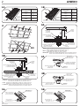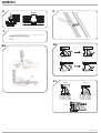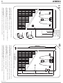
1
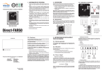
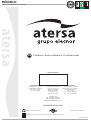
MÓDULO
Manual de Usuario e Instalación
ES
UNE-EN ISO 9001
UNE-EN ISO 14001
OHSAS 18001
ER-0979/1997
GA-2009/0396
SST-0134/2012
Módulo Fotovoltaico Profesional
DISTRIBUIDOR
ATERSA MADRID
C/ Embajadores, 187 - 3º
28045 Madrid - España
Tel: 915 178 452
Fax: 914 747 467
ATERSA VALENCIA
P.Industria Juan Carlos I
Avda. de la Foia, 14
46440 Almussafes
Valencia - España
Tel: 902 545 111
Fax: 902 503 355
ATERSA ITALIA
Centro Direzionale Colleoni
Palazzo Liocorno - ingresso 1
20864 Agrate Brianza
(MB) - Italia
Tel: +39 039 2262482
Fax: +39 039 9160546
Teléfonos Intl.
Tel. +34 961 038 430
Fax.+34 961 038 432
E-Mail: [email protected]
(www.atersa.com)
Impreso en papel reciclado
ASSOCIATION
Última revisión: 05/02/14
Depositar el equipo en un punto verde, una vez finalizada su vida útil
ES-MU-41 (4)-A
2
MÓDULO
Manual de Usuario e Instalación
1.- ADVERTENCIAS
No seguir estas instrucciones puede llevar a la destrucción del aparato o a daños personales.
x
Asegúrese de que se siguen las instrucciones de instalación incluidas en este documento. No se aceptarán garantías o reclamaciones si no se ha seguido el proceso descrito.
x
Las instrucciones de seguridad contenidas en este manual tienen que ser seguidas estrictamente para garantizar la seguridad del usuario.
x
El camino para los cables debe proporcionar soporte mecánico a los conductores y disponer de la protección adecuada, según el Reglamento Electrotécnico de Baja Tensión (REBT).
x
Manipular por personal cualificado. Los módulos generan electricidad al ser expuestos a la luz. La conexión de varios módulos en serie puede generar tensiones peligrosas. Para reducir
riesgos eléctricos durante la instalación es conveniente tapar los módulos con algún material opaco. No tocar los terminales con ambas manos y utilizar siempre herramientas
aislantes para las conexiones eléctricas.
x
La inversión de polaridad destruye los diodos bypass de la caja de conexión.
x
No deberá emplearse el módulo bajo luz solar concentrada.
x
En condiciones normales, un módulo puede producir más corriente o tensión del indicado en las condiciones estándar de medida. Por tanto a la hora de dimensionar la capacidad de los
accesorios (cables, fusibles...) Los valores de Isc y Voc se multiplicarán por el factor de 1,25.
x
NO manipular los módulos por la parte central de los largueros de aluminio largos.
2.- EMPLAZAMIENTO E INCLINACIÓN
Los módulos se pueden instalar en solares, terrazas, tejados y patios, pero también en fachadas, ventanas, balcones, paredes y cornisas, para ello
ATERSA dispone de una serie de accesorios.
Para el perfecto funcionamiento de los módulos es fundamental que nunca existan obstáculos que les puedan dar sombra, al menos durante las horas
centrales del día (vegetación, nieve, otros edificios, elementos constructivos, otros módulos, etc...).
Los paneles tienen que orientarse hacia el sur si nos encontramos en el hemisferio norte. A continuación una aproximación para obtener la máxima energía
anual en una instalación fija, se establecerá un periodo de diseño para calcular el dimensionado del generador en función de las necesidades de consumo y
la radiación. Para determinar la inclinación óptima utilizaremos la siguiente tabla: 1A
No instalar el módulo solar en una localización donde pudiera estar inmerso en agua o continuamente expuesto a agua como puede ser un aspersor.
La instalación en ambientes salinos debe realizarse con aisladores para evitar la corrosión galvánica entre el módulo y su estructura soporte.
Los módulos solares conectados en serie deben ser instalados en la misma orientación y ángulo. Además deberemos separarlos de la superficie un mínimo
de 30cm. para su correcta ventilación. 2
IMPORTANTE: NO instalar los módulos con la caja de conexiones en la parte inferior.
El diseño de los módulos de ATERSA permite la evacuación del agua (el tubo interior de los marcos está abierto en sus extremos).
3.- INSTALACIÓN
Los módulos han de ser instalados sobre estructuras fijas y autónomas, éstas nunca deben transmitir esfuerzos sobre los paneles.
3.1.- Instalación Mecánica
3.1.1.- Directamente Sobre la Estructura
Los laterales largos del marco de aluminio de los módulos disponen de una serie de taladros de 6,7mm de diámetro. Para su instalación sobre estructura, se
recomienda utilizar tornillería de M6 de acero inoxidable. El par de apriete necesario para la fijación de la tornillería estará comprendido entre 6 y 8Nm. La
tornillería adecuada es la siguiente: 3A
La ubicación de los tornillos, siempre será a la distancia B (excepto para módulos con formato ½ 6” 4x9, donde la distancia será C), tal y como aparece en la
imagen 12. Se deberán colocar un mínimo de 4 fijaciones por módulo.
3 .1.2.- Sistema de Fijación Hook
12
Los marcos de aluminio de los módulos fotovoltaicos de ATERSA disponen de unos canales laterales que facilitan la colocación del módulo sobre los perfiles
de la instalación.
Para la instalación de los módulos utilizaremos el Sistema de Fijación Hook. Pudiendose instalar éste sobre estructuras estándar o perfiles guía tipo “U”.
Instalación en estructuras estándar:
El montaje se realiza sobre estructuras estándar mediante la grapa, el tornillo Allen M8x20 dentado bajo cabeza, arandela plana y tuerca M8.
4A
Instalación sobre carril guía tipo “U”:
Para realizar éste tipo de instalación es necesario un perfil perforado tipo “U” de 41x41mm ó 41x21mm. Estos elementos no se suministran con el sistema
de Fijación Hook.
El conjunto montado queda tal y como se puede apreciar en la siguiente imagen:
5A
*Nota: En ambientes corrosivos (niebla salina) colocar arandelas de nylon para aislar el panel de las partes metálicas de la estructura.
Instalación
Colocar los dos conjuntos de fijación iniciales, alineados entre sí verticalmente. Enroscar el tornillo Allen hasta el final.
6
Colocar otros dos conjuntos de fijación alineados verticalmente y desplazarlos por el carril hasta hacer tope con el panel.
Comprobar que los módulos estén alineados verticalmente y horizontalmente entre sí y proceder a enroscar los tornillos hasta su límite, consiguiendo así
que éstos queden fuertemente sujetados al carril guía.
La colocación de los conjuntos de fijación finales es de igual forma que la de los conjuntos iniciales pero en sentido inverso, partimos de un módulo ya
colocado y luego colocamos los conjuntos de fijación.
El par de apriete de los tornillos debe estar comprendido entre 16 y 19Nm.
El posicionamiento de la grapas de fijación, ya sean tipo Hook o de otro tipo, será siempre a la distancia B que aparece en la imagen 12 (excepto para
módulos con formato ½ 6” 4x9, donde la distancia será la C). Se colocarán un mínimo de 4 grapas por módulo.
3.2.- Instalación Eléctrica
12
3.2.1.- Conexión eléctrica Caja de Conexiones
SECCIÓN DEL CABLEADO (Sección de cobre):
Utilizar secciones de cables apropiados (*) para evitar caídas de tensión que provoquen pérdida de la potencia de la instalación. Como referencia, no se
debe admitir una caída de la tensión superior al 1,5%.
(*)Consultar tabla de intensidades máx. del fabricante del cable y normativa aplicable.
ES-MU-41 (4)-A
3
MÓDULO
Manual de Usuario e Instalación
SECCIÓN TOTAL (Diámetro externo):
Se puede realizar una conexión directa a la caja de conexiones usando cableado (max. 4mm2 ,AWG12) en el terminal resorte para cables de la caja de
conexión tal y como se muestra a continuación. Cable de dimensiones AWG14 (4mm2) y AWG12 (2.5mm2) puede ser usado. Los prensaestopas admiten
cableado con un diámetro de aislamiento de hasta 8.0 mm (0.31 pulgadas) de diámetro. Para garantizar un pelado adecuado del cable, el aislamiento debe
ser eliminado como se muestra en la figura
CONEXIÓN ELÉCTRICA:
7
Para cableado multifilar, se recomienda el uso de pasadores o por lo menos torsionar el paquete de hebras para asegurar que todos los filamentos se
capturan en el terminal resorte de la caja de conexión. Para abrir la ventana del terminal resorte, donde se ubicará el cableado, colocar un destornillador
verticalmente como se muestra en la figura 1 y presionar sobre el terminal resorte. 8A Es en este momento cuando el cable puede ser insertado en el
terminal resorte (figura 2). Una vez ubicado el cable levantar el destornillador y el cable quedará fijado. Atención a la polaridad de los cables.
Una vez instalado el cable, apretar el presaestopas para comprimir la junta sobre el cable. El par de apriete de la tuerca del prensaestopas será como max.
1.5 Nm (0.34 lbf) depende del tipo de aislamiento del cable.
2
La caja de conexiones con presasestopas integrados admite cables de 4mm (AWG12). Se recomienda una llave fija de 13 mm. (0.51 pulgadas).
El cable tiene que cumplir los requerimientos para ser utilizado en instalaciones fotovoltaicas. El cable que ATERSA utiliza en sus módulos es un cable para
exteriores resistente UV, doble aislamiento, 1kV, rango de temperatura de trabajo entre -40ºC y 110ºC, rango 600/1000 V.
Para que la caja de conexiones mantenga la certificación de seguridad Class II, los cables tendrán que ser también Class II.
La conexión en serie de un número de paneles no debe superar la Vmax del sistema (Ver datos eléctricos del panel).
3.2.2.- Conexión a tierra
Conectar los módulos y la estructura soporte al mismo punto de toma de tierra con lo que nos aseguraremos que cualquier derivación de corriente hacia
cualquiera de los componentes de la instalación no llegue en ningún caso al instalador o al usuario.
El material del marco del módulo es aluminio. Los cables de tierra deben estar conectados al punto de tierra del marco (ver figura 9). La sección del cable de
tierra debe ser de 4mm2.
Para conectar a tierra los módulos, debe usar un tornillo de acero inoxidable rosca-plancha de 4,2mm de diámetro y una longitud comprendida entre 4,5 y
16mm. Esto irá unido a un terminal de ojete semiaislado de 4mm2.
9
Aségurese de que el terminal este correctamente situado entre el cable y el marco del módulo. El terminal debe estar correctamente engastado en el cable
y debe hacer contacto perfectamente con el marco de aluminio.
Existen dos taladros en el módulo solar para este fin, estos están marcados con un símbolo de toma de tierra (ver figura 12), su diámetro es de 4mm. El par
de apriete necesario para la fijación del tornillo estará comprendido entre 1,5 y 2Nm.
El sistema fotovoltaico estará puesto a tierra conforme a los reglamentos locales y nacionales.
3.3.- Instalación y guiado del cableado eléctrico
Todo cable utilizado para la instalación debe quedar sujeto para evitar movimientos que puedan ocasionar deterioros o roturas del mismo.
ATERSA dispone de una Brida para la instalación y guiado de estos cables.
Utilizando la Brida Hook se facilita en gran medida el guiado y sujeción a lo largo del marco de alumínio de los cables de conexiones. 10
La Brida Hook puede ser utilizada tanto en el perfil Hook V1 como en el Hook V4 y la correcta ubicación de la misma en los perfiles es la que se describe en
los gráficos siguientes:
11
4. - M A N T E N I M I E N T O
Los módulos solares de ATERSA apenas necesitan mantenimiento. Bastaría con revisar periódicamente que no se acumule suciedad sobre el
cristal del panel; si fuese necesario lo limpiaríamos con una esponja y agua jabonosa, nunca utilizar productos abrasivos que puedan dañar el cristal. NO
limpiar con agua a presión y evitar limpiar cuando más calientes están (mediodía).
Comprobar los cables y conexiones eléctricas. Comprobar que los componentes mecánicos se encuentren libres de daños.
Realizar el mantenimiento por personal cualificado, dado que se puede estar trabajando con tensiones peligrosas.
5.- ESPECIFICACIONES TÉCNICAS
Los módulos solares están construidos con células cuadradas de alta eficiencia, capaces de producir energía con baja radiación solar. Todos los modelos
desde 70W hasta 300W llevan diodos de by-pass dentro de la caja de conexiones.
Las características técnicas de los módulos aparecen en las siguientes tablas y gráficos.
6.- GARANTÍA Y CERTIFICADOS
ATERSA garantiza hasta 25 años la potencia de salida y 10 años los defectos de fabricación.
Según la norma IEC 61730-1, la clase de aplicación de este producto (módulo ATERSA) es la clase A, que corresponde a aquellos módulos que están
funcionando a tensiones mayores de 50V o a potencias mayores de 240W, donde el acceso a un contacto general está previsto. Los módulos que están
clasificados para seguridad dentro de esta categoría reúnen los requerimientos para Clase II.
Todos los módulos ATERSA cumplen las normas IEC 61215:2005 e IEC 61730 además de estar fabricados bajo las normas de calidad UNE-EN ISO
9001:2008 y UNE-EN ISO 14001:2004.
Los formatos 6” 6x10 y 6” 6x12 también están certificados UL 1703.
Para una información más exhaustiva de los términos de la garantía, pueden consultar nuestra web: www.atersa.com
*Nota: ATERSA se reserva el derecho de modificar las especificaciones del producto sin previo aviso.
Todas las imágenes a las que se hace referencia mediante numeración
X
en este manual se encuentran en el anexo.
ES-MU-41 (4)-A
MÓDULO
4
Manual de Usuario e Instalación
A-295P
A-300P
A-290P
14,74%
8,33 A
15,04%
29,53 V
8,45 A
15,35%
35,33 V
7,93 A
14,39%
35,63 V
8,00 A
14,65%
35,93 V
8,07 A
14,91%
36,23 V
8,14 A
15,16%
36,52 V
8,21 A
15,42%
A-285P
14,43%
8,21 A
29,37 V
8,89 A
A-280P
300 W
14,12%
8,10 A
29,21 V
8,78 A
A-250P
295 W
(0/+5 W)
13,82%
7,99 A
29,04 V
8,67 A
A-245P
290 W
(0/+5 W)
A-240P
285 W
(0/+5 W)
A-235P
280 W
(0/+5 W)
15,42%
7,88 A
28,87 V
8,56 A
A-230P
250 W
(0/+5 W)
14,39%
8,41 A
28,70 V
8,45 A
A-225P
245 W
(0/+5 W)
A-150P
240 W
(0/+5 W)
A-140P
235 W
(0/+5 W)
A-75P
230 W
(0/+5 W)
A-70P
225 W
(0/+5 W)
CARACTERÍSTICAS ELÉCTRICAS
150 W
(0/+5 W)
6” 6x12
140 W
± 5%
6” 6x10
75 W
± 5%
6” 4x9
70 W
± 8%
½ 6” 4x9
Potencia
± 8%
Formato
Tolerancia
14,63%
7,98 A
17,84 V
8,91 A
72
13,65%
4,21 A
17,54 V
8,82 A
60
3,99 A
17,84 V
8,73 A
36
Eficiencia del módulo
17,54 V
8,64 A
36 ½
Corriente Pto Máxima Potencia (Imp)
8,55 A
Número de células en serie
Tensión Pto Máxima Potencia (Vmp)
8,46 A
0,04%/ºC
8,69 A
-0,32%/ºC
8,42 A
-0,43%/ºC
4,35 A
0,04%/ºC
1000 V
4,21 A
0,04%/ºC
-0,32%/ºC
1965x990x40
Corriente en Cortocircuito (Isc)
-0,32%/ºC
-0,43%/ºC
No
44,97 V
0,04%/ºC
-0,43%/ºC
1000 V
938
44,82 V
-0,32%/ºC
1000 V
1645x990x40
445,5
44,67 V
-0,43%/ºC
1476x659x35
938
1639x984x32
660,5
44,52 V
1000 V
No
284,5
982,5
44,37 V
778x659x35
619
500,5
24
37,60 V
No
200
822,5
Hook V4
37,38 V
619
416
21,50
TYCO IP65
37,16 V
68
738
Hook V4
Si (1250mm, Negro)
36,94 V
Coeficiente Temperatura de Isc (α)
192
11,90
TYCO IP65
3 / SCHOTTKY Sl1010
36,72 V
Coeficiente Temperatura de Voc (β)
389
Hook V1
Si (1100mm, Negro)
36,50 V
Coeficiente Temperatura de P (γ)
6,20
TYCO IP65
3 / SCHOTTKY Sl1010
22,60 V
A (mm) (Figura 12)
Dim. Laminado (mm ± 2mm; Fig. 13)
Hook V1
No
22,30 V
B (mm) (Figura 12)
TYCO IP65
2 / SCHOTTKY Sl1010
20,25 A
18A / 45V / m175ºC
22,60 V
C (mm) (Figura 12)
No
20,25 A
18A / 45V / m175ºC
22,30 V
D (mm) (Figura 12)
2 / SCHOTTKY Sl1010
20,25 A
18A / 45V / m175ºC
Tensión de Circuito Abierto (Voc)
Peso (kg aprox)
20,25 A
18A / 45V / m175ºC
15
2
41
15
2
24
15
2
21
15
Diodos Protección (Nº/Tipo)
Cables (**)
Caja conexiones (*)
Perfil tipo
Dimensiones Panel (mm ± 2mm)
CARACTERÍSTICAS FÍSICAS
Máxima Tensión del Sistema
Corriente Inversa Máx. (durante 2h)
Diodos Protección (Amperios/Vmax/Tj)
Fusible en Serie (A) (***)
2
43
*** Protección contra sobreintensidades (Max. recomendado).
**** Sin ninguna protección adicional.
Nº Máx. Paneles en Serie
* Tyco Electronics Corporation.
2
** Cable Solar 4mm
Nº Máx. Paneles en Paralelo (****)
Especificaciones eléctricas medidas en STC. TONC: 47±2ºC
ES-MU-41 (4)-A
MODULE
Installation and User Manual
N
UNE-EN ISO 9001
UNE-EN ISO 14001
OHSAS 18001
ER-0979/1997
GA-2009/0396
SST-0134/2012
Professional Photovoltaic Module
DISTRIBUTOR
ATERSA MADRID
C/ Embajadores, 187 - 3º
28045 Madrid - Spain
Tel: 915 178 452
Fax: 914 747 467
ATERSA VALENCIA
P.Industria Juan Carlos I
Avda. de la Foia, 14
46440 Almussafes
Valencia - Spain
Tel: 902 545 111
Fax: 902 503 355
ATERSA ITALY
Centro Direzionale Colleoni
Palazzo Liocorno - ingresso 1
20864 Agrate Brianza
(MB) - Italy
Tel: +39 039 2262482
Fax: +39 039 9160546
Intl. Phone numbers
Tel. +34 961 038 430
Fax.+34 961 038 432
E-Mail: [email protected]
(www.atersa.com)
Printed on recycled paper
ASSOCIATION
Latest revision: 05/02/14
Dispose of the device at an environmental disposal point when it reaches the end of its useful life
EN-MU-41 (4)-A
2
MODULE
Installation and User Manual
1.- WARNINGS
Failure to follow these instructions could result in the destruction of the equipment or personal injury.
x
Ensure that the installation instructions provided in this document are followed. Guarantees or claims will not be valid if the described process has not been followed.
x
The safety instructions contained in this manual must be strictly followed in order to guarantee the safety of the user.
x
The cable pathway must provide mechanical support for the conductors and must provide sufficient protection, in accordance with the Low Voltage Electrotechnical Regulations
(REBT).
x
It must be handled by qualified personnel only. When exposed to the light, the modules generate electricity. If several modules are connected in series, dangerously high voltages may
be generated. To reduce potential electrical hazards during the installation process, it is advisable to cover the modules with an opaque material. Do not touch the terminals with both
hands and always use insulated tools on the electrical connections.
x
Reversing the polarity of the cables destroys the bypass diodes of the junction box.
x
The module is not suitable for use under concentrated sunlight.
x
In normal conditions, the module can produce more current or voltage than the indicated for standard measurement conditions. So that, when dimensioning the system (cables
section, fuses,…) the Isc and Voc values should be multiplied by 1,25.
x
Modules must NOT be manipulated from the central part of the long sides of the frame.
2.- POSITIONING AND INCLINATION
The modules may be installed on plots of land, terraces, roofs and patios. ATERSA provides a series of accessories for installations on façades, windows,
balconies, walls and cornices.
In order to ensure optimum performance the modules must not be placed in the shadow of other objects (plants, snow, buildings, construction elements,
other modules, etc.), at least during the main hours of daylight.
The panels must face south if installed in the northern hemisphere.Guidelines for achieving maximum annual power output from a fixed installation are
provided below. A design period will be established in order to calculate the size of generator in accordance with the consumption requirements and
radiation. To determine the optimum inclination we will use the following table: 1A
Do not install the solar module in a location where it could be immersed in water or continually exposed to water, e.g. from a sprinkler.
The installation in a saline environment must be done with isolators to prevent galvanic corrosion between the module and the support structure.
When solar modules are connected in series, they must all face the same direction and have the same angle of inclination. There must also be a proper gap
(minimum 30cm) between the module and the surface for ventilation purposes. 2
IMPORTANT: Do NOT install the modules with the junction box in the lower side.
The ATERSA modules design allows the correct evacuation of water. They have open edges in the inside tube.
3.- INSTALLATION
The modules must be installed on independent fixed structures. The structure must not transmit stress to the modules.
3.1.- Mechanical Installation
3.1.1.- Directly on the Structure
The longest side of the aluminium frame has a series of 6,7mm diameter drill holes. Use M6 stainless steel screws to install it on the structure and the
proper torque values should be between 6 to 8Nm. The following screw system should be employed: 3A
The placement of the screws, will be always at the distance B (except for ½ 6” 4x9 format modules, where the distance must be C), as shown in the image
number 12. Minimum 4 screws per module must be situated.
3 .1.2.- Hook Fixing System
12
The aluminium frames of ATERSA’s photovoltaic modules have side channels that make it easier to fix the module onto the profiles of the installation.
The Hook Fixing System is used to install the modules.This system can be installed on standard structures or “U” type guide rail.
Installation on standard structures:
Fixing on standard structures is carried out using the dead-end clamp, the M8x20 serrated head Allen screw, flat washer and M8 nut.
4A
Installation on “U” type guide rail:
For this type of installation you need a 41x41mm or 41x21mm "U" type perforated profile. These elements do not come with the Hook Fixing System.
The assembled fixing should look like the picture shown in next figure:
5A
*Note: In corrosive environments (salt spray), place nylon washers to insulate the panel from the metal parts of the structure.
Installation
Put the first two fixing sets in place, and ensure they are vertically aligned. Fully tighten the Allen screw.
6
Attach the other two fixing sets, aligning them vertically and move them along the rail until they reach the panel.
Check that the modules are horizontally and vertically aligned and fully tighten the screws to ensure the modules are firmly fixed to the guide rail.
The final fixing sets should be attached in the same way as the first two but in reverse. Take a module that is already in place and then attach the set of
fixings.
The proper torque values should be between 16 to 19Nm.
The placement of the dead end clamp (Hook clamp or another type), will be always at the distance B (except for ½ 6” 4x9 format modules, where the
distance must be C), as shown in the image number 12. Minimum 4 dead end clamps per module must be situated.
3.2.- Electrical Installation
12
3.2.1.- Electrical Connection of the Junction Box
CABLE SECTION (Copper section):
Appropriate cable sections must be used (*) to prevent voltage drops, which could cause a drop in the power of the installation. As a rule, voltage drops in
excess of 1,5% must not be allowed.
(*)Check table of intensities max. of manufacturer's cable and the applicable regulations.
EN-MU-41 (4)-A
3
MODULE
Installation and User Manual
TOTAL SECTION (External diameter):
A direct cable connection can be made to the direct connect junction box using (max. 4mm2,AWG12) the cable termination spring clips in the junction box.
In the manner shown below, direct connection of cable sizes AWG14 and AWG12 can be accommodated. The sealing grommet in the 2 rail assembly can
accommodate insulation diameters up to 8.0mm (0.31 inches). To ensure proper termination, cable insulation should be stripped as shown in figure
7
ELECTRICAL CONNECTION:
On multi-stranded conductors, it is recommended to use wire pins or at least to twist the strand bundle to ensure all strands are captured in the spring clip.
To open the spring clip window for the cable, a little screw is inserted vertically into the window as seen in figure 1. 8A The cable can be inserted through the
opened window into the clip (figure 2). Once the cable is installed, lift the screw and the cable is fixed. Attention to the polarity of the wires.
After termination, tighten the grommet nut to compress the grommet around the cable. Tightening torque for cable screw nut max. 1.5 Nm (0.34 lbf)
depends on the type of cable isolation. Hold cable screw joint with tool.
Connection boxes with integrated cable glands are used with 4mm² cable (AWG 12). The tightening torque is 1.3 +0.2 Nm (0.29 lbf). For this is recommended
the use of a slotted socket wrench with wrench size oh 13mm (0.51 inches). ,
The cable must fulfill the requirements to be used in photovoltaic systems. The cable used by ATERSA in its modules is for outdoors use, UV resistent,
double isolation layer, 1kV, working temperature range -40ºC to 110ºC, rated 600/1000 V.
For the junction box to maintain its Class II safety standard, the cables must also be Class II.
It is not recomended to connect modules in series with a total Voc higher than the system Vmax shown at the module label.
3.2.2.- Ground connection
Connect the modules and the support structure to ground, which will ensure that any current leakage to any of the components of the installation will not
reach the installer or user under any circumstances.
The module frame material is aluminium. Ground wires must be connected to the module’s frame at the ground location (Figure 9). The ground wire must
be 4mm2.
To ground the modules, you must use a stainless steel lug terminal 4mm2 and a self-tapping screw between 4,2x4,5mm and 4,2x16mm. Terminal lug and
self-tapping screw must be stainless steel.
9
Make sure the lug terminal is placed between the wire and module frame. The wire must fully clamped with the lug terminal and must make good contact
with the frame.
There are two drill holes in the solar modules for this purpose, which are marked with a ground connection (Earthing hole 4mm) (Figure 12). The proper
torque values should be between 1,5 to 2Nm.
The photovoltaic system will be earthed according to the local and national regulations.
3.3.- Installation and guiding of the electrical cables
All the cables used in the installation must be secured in order to prevent movements that could cause damage or breakages.
ATERSA supplies a Clamp for the installation and guiding of these cables.
The Hook Clamp greatly assists the task of guiding and securing the connection cables along the length of the aluminium frame.
The Hook Clamp can be used on both the Hook V1 and Hook V4 profiles. The correct placing of it is the one shown in figure:
10
11
4. - M A I N T E N A N C E
ATERSA solar modules hardly require any maintenance. It is sufficient to regularly check that dirt has not accumulated on the glass of the panel. Should this
be the case, clean the glass with a sponge and soapy water. Never use abrasive products that could damage the glass. Do NOT use water jet cleaning
systems. Do not clean the panels at their hottest (midday).
Check the cables and electrical connections. Check that the mechanical components are not damaged.
Maintenance work should be carried out by qualified personnel, as it could involve working with dangerously high voltages.
5.- TECHNICAL SPECIFICATIONS
Our solar modules are made from high-efficiency square cells that are capable of producing power with low solar radiation. All the models from 70W to
300W have by-pass diodes in the junction box.
The technical characteristics of the modules are shown in the attached table and grapichs.
6.- GUARANTEE AND CERTIFICATES
ATERSA guarantees the power output for up to 25 years and provides a 10-year warranty covering manufacturing flaws.
According to the norm IEC 61730-1, the application class for this product (ATERSA module) is class A, which corresponds to modules working in voltages
above 50V or powers above 240W where the access to a general contact is forecasted. The modules clasified for security within this category fulfill the
requirements for ClassII.
The modules comply with IEC 61215:2005 and IEC 61730 standards, in addition to being manufactured under strict UNE-EN ISO 9001:2008 and UNE-EN
ISO 14001:2004 quality standards.
The modules 6” 6x10 and 6” 6x12 are also certified by UL 1703.
For more extensive information about the terms of the warranty, please see our website: www.atersa.com
*Note: ATERSA reserves the right to modify the product specifications without notice.
All images that are referenced by numbers
X
in this manual are found in the Annex.
EN-MU-41 (4)-A
MODULE
4
Installation and User Manual
A-295P
A-300P
A-290P
14,74%
8,33 A
15,04%
29,53 V
8,45 A
15,35%
35,33 V
7,93 A
14,39%
35,63 V
8,00 A
14,65%
35,93 V
8,07 A
14,91%
36,23 V
8,14 A
15,16%
8,89 A
36,52 V
8,21 A
15,42%
A-285P
14,43%
8,21 A
29,37 V
8,78 A
A-280P
300 W
14,12%
8,10 A
29,21 V
8,67 A
A-250P
295 W
(0/+5 W)
13,82%
7,99 A
29,04 V
8,56 A
A-245P
290 W
(0/+5 W)
A-240P
285 W
(0/+5 W)
A-235P
280 W
(0/+5 W)
15,42%
7,88 A
28,87 V
8,45 A
A-230P
250 W
(0/+5 W)
14,39%
8,41 A
28,70 V
8,91 A
A-225P
245 W
(0/+5 W)
A-150P
240 W
(0/+5 W)
A-140P
235 W
(0/+5 W)
A-75P
230 W
(0/+5 W)
A-70P
225 W
(0/+5 W)
ELECTRICAL CHARACTERISTICS
150 W
(0/+5 W)
6” 6x12
140 W
± 5%
6” 6x10
75 W
± 5%
6” 4x9
70 W
± 8%
½ 6” 4x9
Power
± 8%
Format
Tolerance
14,63%
7,98 A
17,84 V
8,82 A
72
13,65%
4,21 A
17,54 V
8,73 A
60
3,99 A
17,84 V
8,64 A
36
Module Efficiency
17,54 V
8,55 A
36 ½
Max. Power Current (Imp)
8,46 A
Number of cells in series
Max. Power Voltage (Vmp)
8,69 A
0,04%/ºC
8,42 A
-0,32%/ºC
4,35 A
-0,43%/ºC
4,21 A
0,04%/ºC
1000 V
Short-circuit Current (Isc)
0,04%/ºC
-0,32%/ºC
1965x990x40
44,97 V
-0,32%/ºC
-0,43%/ºC
No
44,82 V
0,04%/ºC
-0,43%/ºC
1000 V
938
44,67 V
-0,32%/ºC
1000 V
1645x990x40
445,5
44,52 V
-0,43%/ºC
1476x659x35
938
1639x984x32
660,5
44,37 V
1000 V
No
284,5
982,5
37,60 V
778x659x35
619
500,5
24
37,38 V
No
200
822,5
Hook V4
37,16 V
619
416
21,50
TYCO IP65
36,94 V
68
738
Hook V4
Yes (1250mm, Black)
36,72 V
Isc (α) Temperature Coefficient
192
11,90
TYCO IP65
3 / SCHOTTKY Sl1010
36,50 V
Voc (β) Temperature Coefficient
389
Hook V1
Yes (1100mm, Black)
22,60 V
P (γ) Temperature Coefficient
6,20
TYCO IP65
3 / SCHOTTKY Sl1010
22,30 V
A (mm) (Figure 12)
Laminate Dim. (mm ± 2mm; Fig. 13)
Hook V1
No
22,60 V
B (mm) (Figure 12)
TYCO IP65
2 / SCHOTTKY Sl1010
20,25 A
18A / 45V / m175ºC
22,30 V
C (mm) (Figure 12)
No
20,25 A
18A / 45V / m175ºC
Open Circuit Voltage (Voc)
D (mm) (Figure 12)
2 / SCHOTTKY Sl1010
20,25 A
18A / 45V / m175ºC
Protection Diodes (Nº/Type)
Cables (**)
Connection Box (*)
Frame type
Dimensions (mm ± 2mm)
PHYSICAL CHARACTERISTICS
Max. System Voltage
Weight (kg approx)
20,25 A
18A / 45V / m175ºC
15
2
41
15
2
24
15
2
21
15
Max. Reverse Current (during 2h)
Protection Diodes (Amperes/Vmax/Tj)
Serial Fuse (A) (***)
2
43
*** Overcurrent protection (Max. recommended).
**** Without any additional protection.
Max. Nº Modules in Serie
* Tyco Electronics Corporation.
2
** Solar Cable 4mm
Max. Nº Modules in Parallel (****)
Electrical specifications measured in STC. TONC: 47±2ºC
EN-MU-41 (4)-A
ANEXO
ES
N
UNE-EN ISO 9001
UNE-EN ISO 14001
OHSAS 18001
ER-0979/1997
GA-2009/0396
SST-0134/2012
Módulo Fotovoltaico Profesional
Professional Photovoltaic Module
ASSOCIATION
MU-41 (4)-A
2
ANEXO
1A
1B
LUZ SOLAR
SOLAR LIGHT
LUMIÈRE SOLAIRE
INCLINACIÓN
INCLINATION
INCLINAISON
SONNENLICHT
LUCE SOLARE
ZONLICHT
KONZEPTIONSPHASE
PERIODO DI PROGETTAZIONE
PERIODE VAN METING
NEIGUNG
INCLINAZIONE
HELLINGSHOEK
Latitud +10º
Latitude +10º
Latitude +10º
WINTER
INVERNO
WINTER
Breitengrad +10º
Latitudine +10º
Breedtegraad +10º
VERANO
SUMMER
ÉTÉ
Latitud -20º
Latitude -20º
Latitude -20º
SOMMER
ESTATE
ZOMER
Breitengrad -20º
Latitudine -20º
Breedtegraad -20º
ANUAL
ANNUAL
ANNUEL
Latitud -10º
Latitude -10º
Latitude -10º
JÄHRLICH
ANNUALE
JAARLIJKS
Breitengrad -10º
Latitudine -10º
Breedtegraad -10º
PERIODO DE DISEÑO
DESIGN PERIOD
PÉRIODO DE DIMENSIONNEMENT
INCLINACIÓN
INCLINATION
INCLINAISON
INVIERNO
WINTER
HIVER
HORIZONTAL
SUR/SOUTH/SUD
(Hemisferio norte/North hemisphere/Hémisphère nord )
NEIGUNG
INCLINAZIONE
HELLINGSHOEK
HORIZONTAL
SÜD/SUD/ZUID
(Nördliche Hemisphäre/Emisferio settentrionale/Noordelijk halfrond )
3A
2
MARCO
FRAME
CADRE
TORNILLO M6
M6 SCREW
BOULON M6
* ARANDELA PLANA M6
* M6 WASHER
* RONDELLE M6
RECOMENDADO/RECOMMENDED/RECOMMANDÉ
EMPFOHLEN/RACCOMANDATO/AANBEVOLEN
ARANDELA PLANA M6
M6 WASHER
RONDELLE M6
NO
3B
ARANDELA DE PRESIÓN M6
M6 GROWER WASHER
RONDELLE GROWER M6
* Nota: Utilizar Arandela M6 DIN 9021 para perfil Hook V4.
Utilizar Arandela M6 DIN 125 para perfil Hook V1.
* Note: Use M6 DIN 9021 washer for Hook V4 profile.
Use M6 DIN 125 washer for Hook V1 profile.
* Remarque: Utiliser des rondelles M6 DIN 9021 pour les profilés Hook V4.
Utiliser des rondelles M6 DIN 125 pour les profilés Hook V1.
4A
TORNILLO ALLEN M8x20
M8x20 ALLEN SCREW
BOULON ALLEN M8x20
* FLACHE UNTERLEGSCHEIBE M6
* RONDELLA PIANA M6
* VLAKKE SLUITRING M6
ARANDELA PLANA M8
M8 WASHER
RONDELLE M8
FLACHE UNTERLEGSCHEIBE M6
RONDELLA PIANA M6
VLAKKE SLUITRING M6
FEDERUNTERLEGSCHEIBE M6
RONDELLA GROWER M6
BORGRING M6
MUTTER M6
DADO M6
MOER M6
KONSTRUKTION
STRUTTURA
DRAAGFRAME
* Hinweis: Verwenden Sie M6 DIN 9021 für das Profil Hook V4..
Verwenden Sie M6 DIN 125 für das Profil Hook V1.
* N.B.: Utilizzare la rondella M6 Din 9021 per il profilo Hook V4.
Utilizzare la rondella M6 DIN 125 per il profilo Hook V1.
* Voetnoot: Gebruik sluitring M6 DIN 9021 voor profiel Hook V4.
Gebruik sluitring M6 DIN 125 voor profiel Hook V1.
5A
TORNILLO ALLEN M8x20
M8x20 ALLEN SCREW
BOULON ALLEN M8x20
TUERCA GUIA M8
M8 GUIDE NUT
ÉCROU GUIDE M8
MU-41 (4)-A
GRAPA HOOK
DEAD-END CLAMP
PIÈCE FIXATION
RAHMEN
TELAIO
FRAME
SCHRAUBE M6
BULLONE M6
BOUT M6
GRAPA HOOK
DEAD-END CLAMP
PIÈCE FIXATION
TUERCA M6
M6 NUT
ÉCROU M6
ESTRUCTURA
STRUCTURE
STRUCTURE
4B
TUERCA M8
M8 NUT
ÉCROU M8
HOOK-KLAMMER
MORSA HOOK
HOOK-AFSPANKLEM
INBUSSCHRAUBE M8x20
BULLONE ALLEN M8x20
INBUSBOUT M8x20
FLACHE UNTERLEGSCHEIBE M8
RONDELLA PIANA M8
VLAKKE SLUITRING M8
5B
INBUSSCHRAUBE M8x20
BULLONE ALLEN M8x20
INBUSBOUT M8x20
GUIDE MUTTER M8
DADO GUIDA M8
GIDS MOER M8
MUTTER M8
DADO M8
MOER M8
HOOK-KLAMMER
MORSA HOOK
HOOK-AFSPANKLEM
ANEXO
6
0
9
20 -1 mm
7
X= 11mm, 0.43 inches
10
8A
1
2
HOOK V1
HOOK V1
1
2
Figure 1
HOOK V4
11
HOOK V1
HOOK V4
HOOK V4
Figure 2
Para módulos < 180 Wp
For modules < 180 Wp
Pour modules < 180 Wp
Für module < 180 Wp
Per moduli da < 180 Wp
Voor modulen < 180 Wp
Para módulos > 180 Wp
For modules > 180 Wp
Pour modules > 180 Wp
Für module > 180 Wp
Per moduli da > 180 Wp
Voor modulen > 180 Wp
HOOK V1
MU-41 (4)-A
ANEXO
4
12
6,7
A
Dimensiones en mm
Dimensions in mm
Dimensions en mm
Größe in mm
Dimensioni in mm
Afmetingen in mm
38
13
32
984
*
A
B
* Die Flächen in der Zeichnung (A und B) sind für die Fixierung des Laminats bestimmt und eine
ordnungsgemäße Installation.
Es sind grundsätzlich Befestigungssysteme zu gebrauchen, die die Laminierung nicht beschädigen.
A 80 mm.
11 mm. B 13 mm.
9 mm. B 10 mm. (6” 4x9 / ½ 6” 4x9)
* Las áreas marcadas en el dibujo (A y B) están destinadas a la fijación del laminado y
garantizar su correcta instalación.
Utilizar siempre sistemas de fijación que no dañen al laminado.
* Le aree contrassegnate nel disegno (A e B) sono destinati per il fissaggio del laminato e garantire
una corretta installazione.
Utilizzare sempre sistemi di fissaggio che non danneggino il laminato.
5
15
* The areas marked in the drawing (A and B) are intended for the fixation of the laminate and
ensure proper installation.
Always use fastening systems that do not damage the laminate.
HOOK V1
29
HOOK V4
D
* De gebieden gemarkeerd in de tekening (A en B) zijn bestemd voor de fixatie van het laminaat en
zorgen voor een correcte installatie.
Gebruik altijd een montagesysteem dat het laminaat niet kan beschadigen.
1639
225±25.0
595±25.0
595±25.0
225±25.0
40
35
C
* Les zones marquées dans le dessin (A et B) sont destinés à la fixation du stratifié et assurer
une bonne installation.
Toujours utiliser des systèmes de fixation qui n'endommagent pas le stratifié.
MU-41 (4)-A
B