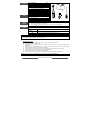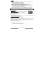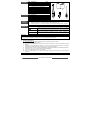
1
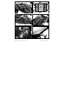
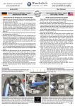
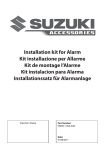
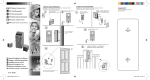
INSTALLATION INSTRUCTIONS
MONTAGEANLEITUNG
INSTRUCTIONS DE MONTAGE
MANUALE DI INSTALLAZIONE
MANUAL DE INSTALACIÓN
GB
D
F
I
E
Description:
Installation kit for
alarm system
Applications:
GSX-R 1000 K9-
Beschreibung:
Installationssatz für
Alarmanlage
Verwendung:
GSX-R 1000 K9-
Désignation:
Kit de montage pour
système d’alarme
Utilisations:
GSX-R 1000 K9-
Descrizione:
Kit di installazione per
sistema d’allarme
Applicazioni:
GSX-R 1000 K9-
Descripción:
Kit de innstalación para
sistema de alarma
Aplicación:
GSX-R 1000 K9-
Part number: 990D0-47H00-ALM
Fitting time: 0.30 h
Teile Nr: 990D0-47H00-ALM
Montagezeit: 0.30 h
n° de code: 990D0-47H00-ALM
Temps d’installation: 0.30 h
Numero di codice: 990D0-47H00-ALM
Tempo d’installazione: 0.30 h
Código: 990D0-47H00-ALM
Tiempo de instalación: 0.30 h
Contents
Tools
Before
installation
Caution
Ref.
1
2
3
4
5
6
7
8
9
Description
Plug & play harness
Sticky wired led 35cm
7,5A fuse
Fixing bi-adhesive tape 55x20x12mm
Fixing bi-adhesive tape 55x35x3mm
Fixing bi-adhesive tape 55x20x17mm
Tie rap 141mm
O-ring 63,50x3,53mm
Installation instructions
Ref.
1
2
3
4
Description
Ratchet
Allen socket 4mm
Screw driver PH3
Suzuki service manual
1.
2.
3.
4.
Q.ty
1
1
1
1
1
1
6
1
1
I
SUZUK
(4)
(1)
(2)
(3)
Park the motorbike steady in a safe place.
Keep the ignition key removed.
Be sure not to damage any vehicle part.
Check that all the parts are contained in the kit as shown in “Contents” section.
Read this manual carefully. “Special” information is described with the following symbols/words.
Take care of these points.
WARNING
Caution
Note
Shows risk for your life and health.
Show risks which can damage your bike.
Contain special information to fit/maintain parts easily.
Caution
Installation of this SUZUKI ORIGINAL ACCESSORY must be performed only by an authorized SUZUKI dealer who
has the proper tools and experience to do the job correctly.
1.
Preliminary operations
a)
b)
c)
d)
e)
f)
g)
h)
Dismount the rear frame cover in accordance to chapter 9D of the service manual.
Disconnect the battery negative pole.
Clean carefully the unit mounting area at the rear frame and the back side of the unit with a suitable cleaner
(picture 1).
Apply the three bi-adhesive foam tapes “4” “5” and “6” to the back side of the alarm unit. Start 7mm from the
outer edge of the connector side as shown in picture 2.
Insert deeply the 18-pin harness connector in the control unit up to the security catch is clicking.
Hook the O-ring “8” to the lower hook on the frame (picture 3-A).
Remove the plastic film from all bi adhesive foam tapes.
Place the alarm unit at the rear frame as indicated in picture 3 and press for a few seconds.
Caution: a space of 3-4mm must be left between the alarm unit and the fairing (picture 3).
i)
2
Mount the O-ring “8” to the upper hook (picture 3-B).
SUZUKI GENUINE ACCESSORIES
2.
Connections
a)
b)
c)
d)
e)
f)
g)
h)
i)
j)
Route the alarm system harness around the rear frame to the original harness and secure it with tie raps
(picture 4)
Route the harness under the rear frame (picture 4-A).
Identify the 4-pin connector (picture 5-A) of the alarm pre-arrangement, remove the counterpart and insert
the corresponding harness connector.
Identify the 1-pin connector (picture 5-B) (+12V) and insert the harness counterpart.
Place the fuse housing as indicated (picture 5-C).
Secure the harness and the fuse housing with three tie raps as shown in picture 5.
Place the LED on the left bike rear fairing (picture 6).
Apply the rear fairing on top of the rear frame close to its original position, identify and disconnect the 2-pin
connectors of the turn signals and interpose the harness counterparts for the right and left turn signals.
Route the LED cable to the harness counter part.
Remount the rear fairing in accordance to the service manual.
Caution: assure that no cables are clamped between the cowling and frame or will get damaged.
k)
Reconnect the negative battery pole and remount the seats and side covers.
3.
System check and test
a)
To arm the system push once BUTTON 1 of the remote control.
Arming is confirmed by:
Turn indicators flash two times (right-left-right-left)
2 acoustic signals (bleep)
LED turns on (quick flash)
•
•
•
The system is operating after 40 sec. «Standby Time»: the motorbike cannot start
b)
c)
d)
•
•
Move the motorbike to test that movement sensor is operating
during 30 sec.
At the end of the alarm phase the LED is steady ON.
To disarm the system push BUTTON 1 of the remote control
Disarming is confirmed by:
Turn indicators flash once (right-left)
1 acoustic signal
LED gives 1 flash every 5 sec. to confirm an alarm due to a position variation
impulse (ON-OFF) on the ignition key.
e)
f)
g)
4.
Led flashes slowly
siren sounds and turn indicators are flashing
to reset the alarm memory give an
To activate the PANIC alarm push once BUTTON 2 of the remote control
the siren sounds and turn indicators
are flashing during 30 sec. (to stop this test push BUTTON 1 or BUTTON 2).
Re-assemble the parts previously removed.
End of installation.
What to be done before delivering the motorbike to its owner
a)
b)
Deliver to the owner the two remotes control together with the metal plate where the releasing emergency
“PIN CODE” is printed.
Explain to the owner the releasing emergency procedure.
SUZUKI GENUINE ACCESSORIES
3
Inhalt
Werkzeuge
Vorbereitung
Ref.
1
2
3
4
5
6
7
8
9
Beschreibung
Anz.
Kabel plug & play
1
Selbstklebende Led mit Kabel 35cm
1
Sicherung 7,5A
1
Doppelseitiges Klebeband 55x20x12mm 1
Doppelseitiges Klebeband 55x35x3mm 1
Doppelseitiges Klebeband 55x20x17mm 1
Kabelbinder 141mm
6
O-ring 63,50x3,53mm
1
Montageanleitung
1
Ref.
1
2
3
4
Beschreibung
Knarrenschlüssel
Inbus-Stecknuss 4mm
Schraubendreher PH3
Werkstatthandbuch SUZUKI
1.
2.
3.
4.
Wichtig
I
SUZUK
(4)
(1)
(2)
(3)
Parken Sie das Fahrzeug an einem sicheren Ort und in stabiler Position.
Ziehen Sie den Zündschlüssel ab.
Achten Sie darauf, dass beim Einbau keine Fahrzeugteile beschädigt werden.
Überprüfen Sie, dass das Montageset alle unter dem Punkt „Inhalt“ aufgelisteten Teile
enthält.
Lesen Sie diese Anleitung gründlich durch. Wichtige Informationen sind mit den folgenden
Symbolen/Wörtern gekennzeichnet. Diesen Punkten sollten Sie besondere Beachtung schenken.
Weist auf mögliche Gefahren hin, die zu Verletzungen oder zum Tod führen
ACHTUNG
können.
Weist auf mögliche Gefahren hin, durch die das Fahrzeug beschädigt
Wichtig
werden könnte.
Liefert spezifische Informationen zur Erleichterung der Installations- oder
HINWEIS
Wartungsarbeiten.
Wichtig
Montage dieses SUZUKI ORIGINAL ZUBEHÖRS darf nur durch einen authorisierten SUZUKI Händler durchgeführt
werden.
1.
Vorbereitende Arbeitsschritte
a)
b)
c)
d)
e)
f)
g)
h)
Die hintere Verkleidung gemäß den Anweisungen in Kapitel 9D des Werkstatthandbuches entfernen.
Den Minuspol der Batterie abklemmen.
Das Rahmenheck an gezeigter Stelle (Abb.1) gründlich mit einem geeigneten Produkt reinigen, ebenso wie
die Unterseite der Alarmzentrale.
Die drei doppelseitigen Klebebänder “4”, “5” und “6” beginnend an der Steckverbinderseite (siehe Abb.2)
mit einem Abstand von 7 mm zur Außenkante auf der Unterseite der Alarmzentrale anbringen.
Den 18-Wege-Stecker des Anschlusskabels komplett in das Steuergerät einstecken und die
Sicherheitssperre einrasten lassen.
Den O-Ring “8” am unteren Haken des Rahmenhecks einhängen (Abb.3-A).
Die Schutzfolie von allen doppelseitigen Klebebändern abziehen.
Die Alarmzentrale gemäß Abb. 3 am Fahrgestell positionieren und einige Sekunden lang festdrücken.
Wichtig: Zwischen der Alarmzentrale und der Verkleidung muss ein Abstand von 3-4 mm eingehalten werden (Abb.3).
i)
4
Den O-Ring “8” am oberen Haken des Rahmenhecks einhängen (Abb.3-B).
SUZUKI GENUINE ACCESSORIES
2.
Anschlüsse
a)
b)
c)
d)
e)
f)
g)
h)
i)
j)
Die Kabel des Alarmsystems um das Rahmenheck herum führen und mit Kabelbindern an der
Originalverkabelung des Kraftrads befestigen (Abb.4).
Die Kabel unter dem Rahmenheck hindurch führen (Abb.4-A).
Den für die Diebstahlsicherung vorgesehenen 4-Pin-Verbinder (Abb. 5-A) ausfindig machen, das Kabelende
entfernen und die entsprechenden Kabelverbinder einführen.
Den 1-Pin-Verbinder (Abb. 5-B) (+12V) ausfindig machen und das Kabelende einführen.
Den Sicherungshalter gemäß der Abbildung (Abb. 5-C) positionieren.
Die Verkabelung und den Sicherungshalter mit drei Kabelschellen befestigen, siehe Abb.5.
Die LED auf der linken hinteren Verkleidung positionieren (Abb.6).
Die hintere Verkleidung auf dem Rahmenheck in der Nähe ihrer ursprünglichen Lage positionieren, die 2Pin-Verbinder der Fahrtrichtungsanzeiger ausfindig machen und abklemmen und die Kabelenden für den
rechten und linken Fahrtrichtungsanzeiger dazwischen klemmen.
Den LED-Verbinder an das Kabelende anschließen.
Die hintere Verkleidung erneut gemäß den Anweisungen des Werkstatthandbuches wieder anbringen.
Wichtig: Kontrollieren, dass keine Kabel zwischen der Verkleidung und dem Fahrgestell eingeklemmt sind, da sie
andernfalls beschädigt werden könnten.
k)
Den Minuspol der Batterie erneut anschließen und den Sitz und die Seitenverkleidungen anbringen.
3.
Prüfung des Systems
a)
Zur Aktivierung des Alarmsystems die TASTE 1 auf der Fernbedienung drücken.
Die Aktivierung wird bestätigt durch:
Zweifaches Blinken der Fahrtrichtungsanzeiger (rechts-links-rechts-links)
Zwei akustische Signale (Piepton)
Einschalten der LED (schnelles Blinken)
Nach Ablauf der Aktivierungszeit (40 Sek.) ist das System eingeschaltet und das Motorrad kann nicht mehr gestartet
werden
LED blinkt langsam.
b)
c)
d)
Das Kraftrad verschieben, um zu überprüfen, ob der Bewegungssensor korrekt funktioniert
und die Fahrtrichtungsanzeiger blinken 30 Sek. lang.
Nach der Alarmphase leuchtet die LED weiter.
Zur Deaktivierung des Alarmsystems die TASTE 1 drücken.
Die Deaktivierung wird bestätigt durch:
Einmaliges Blinken der Fahrtrichtungsanzeiger (rechts-links)
1 akustisches Signal
die Sirene ertönt
Die LED leuchtet alle 5 Sek. lang einmal auf, um anzuzeigen, dass ein Alarm infolge einer Positionsänderung ausgelöst
wurde
zum Rückstellen des Alarmspeichers einen Impuls mit dem Zündschlüssel geben (ON-OFF).
e)
f)
g)
4.
Zur Aktivierung des PANIK-Alarms die TASTE 2 der Fernbedienung drücken
die Sirene ertönt und die
Fahrtrichtungsanzeiger blinken 30 Sek. lang (zur Unterbrechung des Tests die TASTE 1 oder TASTE 2 drücken)
Die vorher ausgebauten Teile erneut anbringen.
Die Installation ist nun abgeschlossen.
Vor der Übergabe des Kraftrades an den Eigentümer
a)
b)
Händigen Sie dem Eigentümer die beiden Fernbedienungen gemeinsam mit der Metallplakette aus, auf der
der „PIN-CODE“ für die Alarmentriegelung angegeben ist.
Erklären Sie dem Eigentümer die Vorgehensweise bei der Alarmentriegelung.
SUZUKI GENUINE ACCESSORIES
5
Contenu
Outils
Réf.
1
2
3
4
5
6
7
8
9
Désignation
Q.tité
Câblage plug & play
1
Led adhésif câblé 35cm
1
Fusible 7,5A
1
Bi-adhésif pour fixage 55x20x12mm
1
Bi-adhésif pour fixage 55x35x3mm
1
Bi-adhésif pour fixage 55x20x17mm
1
Serre câble 141 mm
6
O-ring 63,50x3,53mm
1
Instructions de montage
1
Réf.
1
2
3
4
Désignation
Clef à cliquet
Clef Allen hexagonale 4 mm
Tournevis cruciforme PH3
Instructions de service Suzuki
I
SUZUK
(4)
(1)
(2)
(3)
Avant le
montage
1.
2.
3.
4.
Garer la moto en lieu sûr et sur une surface plane.
Enlever la clef de contact.
Faites bien attention à ne pas endommager toute ou partie de la moto.
Assurez-vous que le kit montage inclue bien toutes les pièces détaillées au par. “Contenu”.
Important
Lire attentivement ces instructions de montage. Les informations “spéciales” sont marquées par
les symboles/mots ci-après. Prêter une attention particulière à ces points-ci.
Indique de possibles situations dangereuses pouvant causer ou des lésions
ATTENTION ou la mort.
Indique de possibles situations dangereuses pouvant causer des dommages
Important
au motocycle.
Indique des informations spécifiques pouvant faciliter l’installation /
Remarque
manutention.
Important
L'installation des ACCESSOIRES D´ORIGINE SUZUKI doit être effectué par un concessionnaire SUZUKI qui a les
outils appropriés et l'expérience adéquate pour pouvoir faire l'installation correctement.
1.
Opérations préliminaires
a)
b)
c)
d)
e)
f)
g)
h)
Démonter le carénage arrière comme décrit au point 9D des instructions de service.
Détacher le pôle négatif de la batterie
En utilisant un produit approprié, bien nettoyer l’endroit où il faudra fixer l’alarme, et le fond de la centrale
(fig.1).
Appliquer les trois bi-adhésifs pour fixage «4» «5» et «6» sur le fond de la centrale d’alarme. Les appliquer
en partant d’une distance de 7mm du côté connecteur comme indiqué en fig.2.
Introduire à fond le connecteur à 18 pôles du câblage dans la centrale en faisant cliquer l’arrêt automatique de sûreté.
Accrocher l’O-ring « 8 » au crochet inférieur du châssis (fig.3-A).
Enlever le film de protection à tous les bi-adhésifs.
Fixer la centrale d’alarme sur le cadre comme indiqué en fig.3 en faisant pression pendant quelques
secondes.
Important: il faut laisser 3-4mm d’espace entre l’alarme et le carénage (fig. 3).
i)
6
Accrocher l’O-ring « 8 » au crochet en haut du cadre (fig.3-B).
SUZUKI GENUINE ACCESSORIES
2.
Branchements
a)
b)
c)
d)
e)
f)
g)
h)
i)
j)
Disposer le câblage de l’alarme autour du carénage arrière et le fixer au câblage de la moto en utilisant des
serre-câbles (fig.4).
Faire passer le câblage au-dessous du châssis arrière fig.4-A).
Identifier le connecteur à 4-pôles (fig.5-A) de la prédisposition alarme, enlever la partie correspondante et
introduire le connecteur correspondant du câblage.
Identifier le connecteur à 1-pôle (fig.5-B) (+12V) et introduire la partie correspondante du câblage.
Placer le porte-fusible comme indiqué (fig.5-C).
Fixer le câblage et le porte-fusible par 3 serre-câbles comme indiqué en fig. 5.
Placer le LED sur le carénage arrière gauche (fig.6).
Ramener le carénage arrière sur la partie en haut du châssis arrière près de sa position d’origine, identifier
les connecteurs à 2-pôles des indicateurs de direction, les débrancher et interposer les parties
correspondantes du câblage pour les deux indicateurs de direction droit et gauche
Relier le connecteur du LED à la partie correspondante du câblage.
Remonter le carénage arrière selon les instructions de service.
Important: prêter bien attention qu’il n’y ait pas de fils écrasés entre le carénage et le châssis, car sinon ceux-ci seront
endommagés.
k)
3.
a)
Relier à nouveau le pôle négatif de la batterie et remonter la selle et les carénages droit et gauche.
Essai du système
Appuyer la TOUCHE 1 de la télécommande pour activer le système d’alarme.
L’activation est confirmée par:
2 clignotements des indicateurs de direction (droit-gauche-droit-gauche)
2 signalisations acoustiques (beep)
allumage du led (clignotement rapide)
Une fois terminé le temps neutre d’activation (40 sec.) le système est opérationnel, et il n’est pas possible de faire
démarrer la moto
le led clignote lentement.
b)
c)
d)
Déplacer la moto pour tester si le capteur anti-soulèvement est actif
direction clignotent pendant 30 sec.
Une fois la phase d’alarme terminée, le led est allumé fixe.
Appuyer la TOUCHE 1 pour la désactivation du système d’alarme
La désactivation est confirmée par:
1 clignotement des indicateurs de direction (droit-gauche)
1 signalisation acoustique
la sirène sonne et les indicateurs de
Le led donne 1 clignotement tous les 5 sec. pour indiquer l’alarme dû à la variation de position
mémoire d’alarme donner une impulsion (ON-OFF) sur la clef de contact.
e)
f)
g)
4.
pour le reset de la
Appuyer la TOUCHE 2 de la télécommande pour l’activation de l’alarme PANIQUE
la sirène sonne et les
indicateurs de direction clignotent pendant 30 sec. (pour stopper ce test appuyer sur la TOUCHE 1 ou la
TOUCHE 2).
Remettre à leur place toutes les pièces démontées.
Fin de l’installation.
Opérations à effectuer avant de livrer la moto au propriétaire
a)
b)
Livrer au propriétaire les deux télécommandes ainsi que la plaquette métallique où se trouve le “CODE
PIN” pour le déblocage d’urgence.
Expliquer au propriétaire la procédure pour le déblocage d’urgence.
SUZUKI GENUINE ACCESSORIES
7
Contenuto
Attrezzi
Preparazione
Importante
Rif.
1
2
3
4
5
6
7
8
9
Descrizione
Cablaggio plug & play
Led adesivo cablato 35cm
Fusibile 7,5A
Biadesivo di fissaggio 55x20x12mm
Biadesivo di fissaggio 55x35x3mm
Biadesivo di fissaggio 55x20x17mm
Fascetta 141mm
O-ring 63,50x3,53mm
Manuale di installazione
Q.tà
1
1
1
1
1
1
6
1
1
Rif. Descrizione
1 Chiave a cricchetto
2 Chiave a bussola maschio
esagonale 4mm
3 Cacciavite a croce PH3
4 Manuale di servizio SUZUKI
1.
2.
3.
4.
I
SUZUK
(4)
(1)
(2)
(3)
Posteggiare il motoveicolo in un luogo sicuro ed in posizione stabile.
Togliere la chiave di accensione.
Prestate attenzione in modo da non danneggiare parti del veicolo.
Accertatevi che il kit di montaggio contenga tutti I pezzi illustrati nella sezione “Contenuto”.
Leggere con attenzione il presente manuale. Le informazioni “speciali” sono indicate con i seguenti
simboli/parole. Prestare particolare attenzione a questi punti.
ATTENZIONE
Importante
Nota
Indica possibili situazioni di pericolo che potrebbero causare lesioni o la morte.
Indica possibili situazioni di pericolo che potrebbero causare danni al veicolo.
Indica informazioni specifiche che possono agevolare l’installazione/ manutenzione.
Importante
L’installazione degli ACCESSORI ORIGINALI SUZUKI deve essere eseguita esclusivamente da una officina
autorizzata SUZUKI che ha l’attrezzatura e l’esperienza necessaria per effettuare questa operazione correttamente.
1.
Operazioni preliminari
a)
b)
c)
d)
e)
f)
g)
h)
Rimuovere la carenatura posteriore come descritto nel capitolo 9D del manuale di servizio.
Scollegare il polo negativo dalla batteria.
Pulire accuratamente con un prodotto adeguato la zona di fissaggio sul telaio e il fondo della centrale
d’allarme (fig.1).
Applicare i tre biadesivo di fissaggio “4” “5” e “6” sul fondo della centrale d’allarme. Partire a 7mm dal bordo
più esterno dal lato connettore come indicato in fig.2.
Inserire a fondo il connettore 18 vie del cablaggio nella centralina facendo agganciare il fermo di sicurezza.
Agganciare l’O-ring “8” al gancio inferiore del telaio (fig.3-A).
Rimuovere la pellicola protettiva da tutti i biadesivo.
Posizionare la centrale d’allarme sul telaio come indicato in fig.3 facendo pressione per qualche secondo.
Importante: è necessario lasciare uno spazio di 3-4mm tra il la centrale d’allarme e la carenatura (fig.3).
i)
8
Agganciare l’O-ring “8” al gancio superiore del telaio (fig.3-B).
SUZUKI GENUINE ACCESSORIES
2.
Collegamenti
a)
b)
c)
d)
e)
f)
g)
h)
i)
j)
Sistemare il cablaggio del sistema d’allarme attorno al telaio posteriore assicurandolo tramite fascette al
cablaggio originale della moto(fig.4).
Far passare il cablaggio sotto il telaio posteriore (fig.4-A).
Individuare il connettore 4-pin (fig.5-A) della predisposizione antifurto, rimuovere la controparte ed inserire il
connettore corrispondente del cablaggio.
Individuare il connettore 1-pin (fig. 5-B) (+12V) ed inserire la controparte del cablaggio.
Posizionare il portafusibile come indicato (fig. 5-C).
Fissare il cablaggio e il portafusibile con tre fascette come indicato in fig.5.
Posizionare il LED sulla carenatura posteriore sinistra (fig.6).
Posizionare la carenatura posteriore sulla parte alta del telaio posteriore in prossimità della sua posizione
originale, identificare e scollegare i connettori 2-pin degli indicatori di direzione ed interporre le controparti
del cablaggio per l’indicatore di direzione destro e sinistro.
Collegare il connettore del LED alla controparte sul cablaggio.
Rimontare la carenatura posteriore secondo quanto riportato sul manuale di servizio.
Importante: accertarsi che nessun filo sia schiacciato tra la carenatura e il telaio o verrà danneggiato.
k)
Ricollegare il polo negativo della batteria e rimontare la sella e le carenature laterali.
3.
Collaudo del sistema
a)
Premere il TASTO 1 del radiocomando per attivare il sistema d’allarme.
L’attivazione è confermata da:
2 lampeggi degli indicatori di direzione (destro-sinistro-destro-sinistro)
2 segnalazioni acustiche (beep)
accensione del led (lampeggio veloce)
Trascorso il tempo neutro d’attivazione (40 sec.) il sistema è operativo e non è possibile avviare il motoveicolo
lampeggia lento.
b)
c)
d)
Spostare il motoveicolo per verificare il funzionamento del sensore antisollevamento
indicatori di direzione lampeggiano per 30 sec.
Trascorsa la fase d’allarme il led è acceso fisso.
Premere il TASTO 1 per disattivare il sistema d’allarme
La disattivazione è confermata da:
1 lampeggio degli indicatori di direzione (destro-sinistro)
1 segnalazione acustica
la sirena suona e gli
Il led emette 1 lampeggio ogni 5 sec. ad indicare l’avvenuto allarme per variazione di posizione
memoria di allarme dare un impulso (ON-OFF) sulla chiave di avviamento.
e)
il led
per resettare la
f)
g)
Premere il TASTO 2 del radiocomando per attivare l’allarme PANICO
la sirena suona e gli indicatori di
direzione lampeggiano per 30 sec. (per interrompere il test premere il TASTO 1 o il TASTO 2).
Riposizionare le parti precedentemente asportate.
Fine installazione.
4.
Operazioni da effettuare prima della consegna del motoveicolo al proprietario
a)
b)
Consegnare al proprietario i due radiocomandi unitamente alla targhetta metallica dove è riportato il
“CODICE PIN” di sblocco d’emergenza.
Spiegare al proprietario la procedura di sblocco d’emergenza.
SUZUKI GENUINE ACCESSORIES
9
Contenido
Herramientas
Preparatorio
al montaje
Ref.
1
2
3
4
5
6
7
8
9
Descripción
Cableado plug & play
Led adhesivo con cable 35cm
Fusible 7,5 A
Bi-adhesivo para ajuste 55x20x12mm
Bi-adhesivo para ajuste 55x35x3mm
Bi-adhesivo para ajuste 55x20x17mm
Faja 141mm
Junta tórica 63,50x3,53mm
Manual de instalación
Ref.
1
2
3
4
Descripción
Llave con carraca
Llave Allen hexagonal 4 mm
Destornillador en cruz PH3
Instrucciones de Servicio Suzuki
1.
2.
3.
4.
Importante
C.dad
1
1
1
1
1
1
6
1
1
I
SUZUK
(4)
(1)
(2)
(3)
Aparcar el moto vehículo en posición segura y superficie horizontal.
Quitar la llave de contacto.
Prestar atención para no dañar ninguna parte del vehículo.
Verifiquen que en el kit de montaje estén incluidas todas las piezas detalladas en el párrafo
“Contenido”.
Leer con cuidado este manual. Las informaciones “especiales” están marcadas con los símbolos/
palabras aquí abajo. Pongan una atención particular en los mismos.
ATENCIÓN Indica eventuales situaciones peligrosas que podrían ser causa de lesiones o de muerte.
Importante
Nota
Indica eventuales situaciones peligrosas que podrían ser causa de daños al moto vehículo.
Indica informaciones especificas que puedan facilitar la instalación /manutención.
Importante
El montaje de ACCESORIOS ORIGINALES SUZUKI debe ser realizado por un taller autorizado SUZUKI ya que
dispone de las herramientas y la experiencia necesarias para realizar el montaje de manera correcta.
1.
Preparatorio
a)
b)
c)
d)
e)
f)
g)
h)
Quitar el carenado trasero como indicado en el párrafo D de las instrucciones de servicio.
Desconectar el polo negativo de la batería.
Limpiar cuidadosamente con un producto apropiado la superficie del bastidor donde fijaran la centralita y el
fondo de la centralita misma (im.1).
Aplicar los tres bi-adhesivos para ajuste “4” “5” y “6” el fondo de la centralita de alarma. Empezar a la
distancia de 7mm del lado conector como indicado en la im.2.
Introducir a fondo el conector de 18 contactos del cableado en la centralita hasta que oiga el “clic” de
seguridad.
Enganchar la junta tórica “8” al gancho inferior del bastidor (im.3-A).
Quitar el film de protección de cada bi-adhesivo.
Colocar la centralita de alarma en el bastidor como se indica en la im.3 presionando durante algunos
segundos.
Importante: tiene que dejarse un espacio de 3-4mm entre la centralita y el carenado (im.3).
i)
10
Enganchar la junta tórica “8” al gancho arriba del bastidor (fig.3-B).
SUZUKI GENUINE ACCESSORIES
2.
Conexiones
a)
b)
c)
d)
e)
f)
g)
h)
i)
j)
Arreglar el cableado del sistema de alarma alrededor del carenado trasero fijándolo al cableado de la moto
por medio de las fajas (im.4).
Desarrollar el cableado bajo del bastidor trasero (im.4-A).
Identificar el conector de 4 contactos (im.5-A) de la predisposición alarma, quitar la parte correspondiente y
introducir el conector del cableado.
Identificar el conector de 1 contacto (im.5-B) (+12V) y introducir la parte correspondiente del cableado.
Colocar el porta-fusible como se indica en im.5-C
Fijar el cableado y el porta-fusible con tres fajas como se indica en im.5.
Colocar el LED en el carenado trasero izquierdo (im.6).
Colocar el carenado trasero en la parte arriba del bastidor trasero cerca de su posición original, identificar el
conector de 2-contactos de los indicadores de direccion, desconectarlos e interponer las partes
correspondientes del cableado para ambos indicadores de dirección.
Ensamblar el conector del LED a la parte correspondiente del cableado.
Colocar de nuevo el carenado trasero como se indica en las instrucciones de servicio.
Importante: asegurarse que no hay ningún hilo entre el carenado y el bastidor porque en caso contrario se dañaría.
k)
Conectar nuevamente el polo negativo de la batería y colocar el asiento y los carenados derecho e
izquierdo.
3.
Comprobación del sistema
a)
Apretar el BOTÓN 1 del mando para activar el sistema de alarma.
La activación es confirmada por:
2 relampagueos de los intermitentes (derecho-izquierdo-der.-izq.)
2 señalizaciones acústicas (beep)
led encendido (relampagueo rápido)
Después del tiempo neutro de activación (40 sec.) el sistema está operativo y no se puede poner en marcha el
vehículo
el led relampaguea lento.
b)
c)
d)
Desplazar el vehículo para comprobar que funcione el sensor anti-levantamiento
intermitentes relampaguean durante 30 sec.
Al termino de la fase de alarma el led se encuentra encendido fijo.
Apretar el BOTÓN 1 para la desactivación del sistema de alarma
La desactivación es confirmada por:
1 relampagueo de los intermitentes (derecho- izquierdo)
1 señalización acústica
la sirena suena y los
El led parpadea 1 vez cada 5 sec. para indicar que hay una alarma debida a la variación de posición
de la memoria de alarma dar una impulsión (ON-OFF) con la llave de contacto.
e)
f)
g)
4.
para el reset
Apretar el BOTÓN 2 de mando para la activación de la alarma PÁNICO
la sirena suena y los intermitentes
parpadean durante 30 sec. (para interrumpir el test apretar el BOTÓN 1 o el BOTÓN 2).
Monte las piezas quitadas anteriormente.
Termino de la instalación.
Indicaciones antes de entregar el vehículo al propietario
a)
b)
Entregar al propietario los dos mandos junto con la plaqueta metálica donde se encuentra el “CÓDIGO
PIN” para el desbloqueo de emergencia.
Expliquen al propietario el procedimiento para el desbloqueo de emergencia.
SUZUKI GENUINE ACCESSORIES
11
1
2
7
mm
7
mm
Developed and manufactured by Sonar Electronic srl, Italy
12
"4"
"5"
"6"
55x20x12
55x35x3
55x20x17
3
4
5
6
SUZUKI GENUINE ACCESSORIES
I-M 990D0-47H00-ALM rev01 20100623