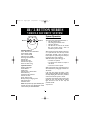
1
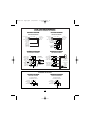
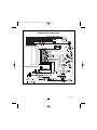
BW1800 art dept.qxd
1/28/2004
1:30 PM
Page 1
1R / 2-BUTTON SERIES
VEHICLE SECURITY SYSTEM
System Operation
Button 1
ARMING OPERATION
To arm the system press transmitter button 1:
• The siren will chirp once.
• The parking lights will flash once.*
• The doors will lock.*
• The LED will turn solid for 10 seconds
then start flashing slowly. After 10
seconds the system is armed.
Button 2
Standard Features:
Two 2- Button Remote Transmitters
Status indicator (LED)
Valet / override switch
Multi-tone siren (120dB)
Dual stage impact detector
Remote panic
Remote chirp mute
Remote sensor bypass
Passive or active arming
After Arming, if the system detects a bad sensor
or an open zone, the siren will chirp and the
parking lights will flash 4 times to indicate a
zone is open. The system will ignore that input,
but keep all other areas protected.
While Armed, the system will trigger if:
• The doors are opened.
• The shock sensor detects an impact to
the vehicle.
• The hood or trunk is opened.
When triggered, the siren will sound, the horn
will honk*, and the parking lights will flash* for
30 seconds.
If the same input triggers the system 3 times
during a single arming cycle,the system will bypass
that input, keeping the other zones protected,
until the next time the system is armed.
If the shock sensor detects a light impact to the
vehicle, the siren will chirp and the parking
lights will flash 5 times to warn away the
potential intruder.
*Optional Feature
Optional Features:
Flashing parking lights
Starter disable
Keyless entry
Remote trunk or hatch release
Illuminated entry
Hood and trunk protection
Remote auto start
Power window roll up
Back-up battery w/charging circuit
Glass break sensor
Microwave sensor
Note: Some features may require additional parts
and labor, and may not be appropriate for certain
vehicles. Consult your authorized dealer.
1
BW1800 art dept.qxd
1/28/2004
1:30 PM
Page 2
PASSIVE ARMING
The passive arming feature allows the system to
arm automatically without user intervention.
The passive arming feature also allows the
system to automatically re-arm itself in the event
the system is disarmed and the ignition is not
turned on within 30 seconds. The Passive Arming
feature may be enabled during installation.
To arm the system passively:
1. Turn the ignition key off.
2. Exit the vehicle and close all doors.
• The LED flashes rapidly indicating that
the system is preparing to arm. (The
system can be armed at any time by
pressing transmitter button 1.)
• If the passive arming with countdown
chirps feature is selected during
installation, the siren will chirp every 2
seconds until armed.
• The siren will chirp 30 seconds after
the last door is closed to indicate the
system is now armed.
• The doors will lock.†*
†
also be programmed for full-time silent
operation during installation.
IGNITION LOCK*
The ignition locking feature automatically locks
the doors 5 seconds after the ignition key is
turned on, and automatically unlocks when the
ignition key is turned off. To avoid locking keys
in the vehicle, the ignition locking feature will be
cancelled if a door is open when the ignition is
turned on. This feature may be disabled during
installation.
REMOTE PANIC
In the event of an emergency (PANIC) situation,
the system’s siren can be triggered for 30
seconds to attract attention.To activate the Panic
Feature, press transmitter button 1 for 3
seconds:
• The siren will sound.
• The parking lights will flash*.
Press button 1 again to exit panic mode. The
Panic Feature will not operate when the
ignition is on.
*Optional feature
If Passive Locking was enabled during installation.
DISARMING OPERATION
To disarm the system press transmitter button 1.
• The siren will chirp twice.
• The parking lights will flash twice.*
• The doors will unlock.*
• The dome light will turn on for 30
seconds.*
EMERGENCY OVERRIDE
If the transmitter becomes lost or fails to
operate, the system can be disarmed by using
the emergency override feature.
To override the system:
1. Enter the vehicle.
• Because the system is armed, the siren
will sound.
2. Turn on the ignition key.
3. Press the Valet switch for 3 seconds.
• The siren will stop sounding.
• The starter defeat will be bypassed.
• The system will enter valet mode.
TAMPER ALERT
If the alarm was triggered while away, the siren
will chirp and the parking lights will flash 3
times on disarming for tamper indication.
SILENT ARMING/DISARMING
Press transmitter button 2 to Arm or Disarm
silently for one-time operation. The system can
2
BW1800 art dept.qxd
1/28/2004
1:30 PM
Page 3
VALET MODE
When the system is placed into the Valet Mode
the security system will be disabled. However,
the optional keyless entry and trunk release
features will still function if installed.
OPTIONAL ANTI-CARJACK FEATURE
The optional anti-carjacking feature provides
added security with three operating modes:
Active, Passive, and Full-time.The Anti-Carjacking
feature must be enabled during installation.
To enter or exit valet mode:
1. Be sure the system is disarmed.
2. Turn the ignition key on.
3. Press and hold the valet switch for 3
seconds.
• The siren will chirp once to enter valet
or twice for exit.
• The LED will turn on solid indicating
the system is in valet mode, or turn off
indicating valet mode exit.
Active. Press transmitter buttons 1&2 with the
ignition on to manually activate the anti-carjack
feature. Press buttons 1&2 again to deactivate
the Active carjack feature.
Passive. When selected, the anti-carjacking
feature will activate whenever a door is opened
while the ignition is on. Press the valet switch
3 times to deactive the Passive carjack feature.
Full-time. When selected, the anti-carjacking
feature will automatically activate each time the
ignition is turned on. Press the valet switch 3
times to deactive the Full-time carjack feature.
OPTIONAL TRUNK RELEASE
Press button 2 for approximately 2 seconds to
open the trunk.
If the carjack feature is triggered:
• The parking lights will flash two times.
• 90 seconds later the parking lights will
flash, the horn will honk, and the siren will
sound for 5 minutes.
• The starter kill will turn on and remain on
until the carjack feature is deactivated.
REMOTE SENSOR BYPASS
To arm the system and bypass the shock sensor,
press button 1 to arm, then within 2 seconds
press buttons 1&2.The siren will chirp once and
sensors will be ignored until the system is
disarmed and rearmed.
PARKING LIGHT INDICATIONS
1 Flash = System Armed
2 Flashes = System Disarmed
3 Flashes = Tamper Alert
4 Flashes = Open Zone Indication (after
arming)
5 Flashes = Shock Sensor Warn-away
STATUS INDICATOR (LED) FUNCTIONS
On Solid = Valet Mode
On Solid when not in valet = Open Zone
Slow Flash = System Armed
Rapid Flash when disarmed = Passive
Arming
Rapid Flash when armed = Tamper Alert
3
BW1800 art dept.qxd
1/28/2004
1:30 PM
Page 4
Installation Instructions
wire from chaffing by installing a proper
size grommet.
Before you begin the installation
• Read the INSTRUCTIONS!
• Always use a multi-meter when verifying
vehicle wiring.
• Before mounting the product, verify with
the customer the desired location for the valet
switch and LED.
• Protect the vehicle by using fender
covers.
• Always look before drilling. Make sure
you will not cause damage to vehicle
hoses, electrical looms or physical damage
to vehicle.
Mounting Shock Sensor
Secure the shock sensor to the steering
column, thick wire harness or a dash brace,
using a wire tie. Make sure that the
adjustment screw is accessible for later
testing and adjustment.
14-Pin Main Harness:
• RED WIRE - +12V Battery input. Connect
the red fused wire on the main harness to a
constant +12V source.This source wire should
be at least 15 amp supply.
• WHITE WIRE - Parking Light output (+) 10A
relay. Connect to the vehicle’s parking light
wire. If the vehicle’s parking light circuit exceeds
10 amps a relay is required. For vehicle’s with
independent left and right parking light circuits,
the parking light wires must be connected using
diodes to keep the circuits separate. A relay is
required for vehicles with negative parking light
circuits. NOTE: Do not connect the WHITE
wire to the vehicle’s headlight circuit.
• BROWN WIRE - Siren wire output (+) 3A.
Connect to the siren’s red wire. Connect the
siren’s black wire to ground.
• BLUE/WHITE WIRE - Not used.
• WHITE/RED WIRE - Not used.
• ORANGE WIRE - Armed Output (-) 500mA.
Connect to a relay for optional starter defeat
(See wiring diagram). The ORANGE wire
Mounting System Module
Mount the system module under the dash
where it will be difficult for a potential
thief to locate the module, and away from
moving parts such as brake pedals, etc.
Route the antenna wire away from wire
looms, computer modules and metallic
objects for better range.
Mounting Siren
Mount the siren in a suitable place under
the hood, away from hot and moving
engine parts such as manifolds, fan belts,
etc. Make sure the siren cannot be
accessed from underneath the vehicle or
through the grill. Face the siren down so
that water cannot accumulate inside the
siren bell. Protect wires running through
the firewall using either tape or split loom
tubing. If a new hole is needed, protect the
4
BW1800 art dept.qxd
1/28/2004
1:30 PM
Page 5
provides a ground when the unit is armed to
activate a starter disable relay or other device
(i.e. window control module, etc.).
• BROWN/WHITE WIRE - Horn output (-)
500mA. Connect to an optional relay to activate
the vehicle’s horn when the alarm is triggered.
• BLACK/WHITE WIRE - Dome Light output
(-) 500mA. Connect to an optional relay to
activate the vehicle’s dome light.
• BLUE WIRE - Trunk/Hood trigger (-).
Connect the Blue wire to the trunk and/or
optional hood pin switches. The switch must
provide a ground output when switch is opened.
• GRAY WIRE - Auxiliary output (-) 500mA.
Connect to a relay for an optional feature such
as trunk release, etc.
• YELLOW WIRE - +12V Ignition input.
Connect to a main ignition wire at the ignition
switch harness.This wire shows +12V when the
ignition is on and while cranking. The voltage
must not drop when the car is starting.
• BLACK WIRE - Ground input (-). Connect to
a solid chassis ground that is clean and free of
paint or dirt.
• VIOLET WIRE - Positive door trigger (+).
Connect to the door switch circuit wire that
shows +12V when the door is open. This type
of door circuit is usually found on Ford vehicles.
• GREEN WIRE - Negative door trigger (-).
Connect to the door switch circuit wire that
shows ground when the door is open.
• RED WIRE - +12V output (+) 300mA for relay
modules, or inverters. Do NOT use as a power
source for door lock relays.
• GREEN WIRE - lock output (-) 500mA.
2-Pin Red Connector: Plug-in connector
port for LED. Mount LED in an area where it
may be easily seen from either side of the
vehicle.
2-Pin Blue Connector: Plug-in connector
port for valet switch. Mount switch in an area
that is easily accessible from the driver’s seat.
4-Pin White Connector: Plug-in connector
port for dual stage shock sensor.
Entering Programming
To enter System Programming:
1. Turn on ignition.
2. Within 5 seconds, press valet switch 5
times.
• The siren will emit a long chirp, to
indicate entering program mode.
3. Press the valet switch the number times
equal to the desired feature.
• The siren will chirp each time the valet
switch is pressed.
4. Within 5 seconds, press the transmitter
button corresponding to the desired
operating mode for that feature.
• The siren will chirp to indicate the
setting.
One chirp = Button 1 (default setting)
Two chirps = Button 2
Three chirps = Buttons 1&2
5. Turn off ignition to save changes.
Plug in Connectors
3-Pin White Door Lock Connector: Plug-in
connector port for door lock harness or
optional door lock relay module.
• BLUE WIRE - unlock output (-) 500mA.
5
BW1800 art dept.qxd
1/28/2004
1:30 PM
Page 6
5. Siren / Horn Chirps. When set for Horn
Chirps the horn will honk when the alarm is
armed, disarmed, and triggered, allowing the
siren to NOT be installed. Buttons 1&2
together add horn chirps with the warn away
feature.
6. Anti-Carjack Activation. Enables or disables
the anti-carjacking feature.
7. Anti-Carjack Mode. Selects one of three
Anti-Carjacking modes: Active, Passive, or FullTime. Anti-Carjack Activation must be enabled
for any Anti-Carjack mode to operate.
Active. Pressing transmitter buttons 1&2 with
the ignition on will manually activate the AntiCarjacking feature.
Passive. When selected, the Anti-Carjacking
feature will activate whenever a door is opened
while the ignition is on.
Full-time. When selected, the Anti-Carjacking
feature will automatically activate each time the
ignition is turned on.
8. Two Stage Disarm. When selected, pressing
the button to disarm the system during a
trigger cycle will instead reset the siren and
leave the alarm armed. Pressing the button
again will disarm the system.
Complete Default Reset
Following this procedure will set all
programmable features to factory default
settings.
1. Enter System Programming.
2 .Press Transmitter Buttons 1&2 together.
• The siren will chirp 6 times indicating the
reset signal was received.
• All programmable features are now set to
factory default settings.
2. Turn ignition off.
Programmable Features
1. Arming Mode. Select between manual
arming (Active), automatic arming (Passive), and
automatic arming with chirps that countdown
every 2 seconds until armed.
2. Passive Locking. Selects whether or not the
system will automatically lock the doors with
Passive Arming.
3. Ignition Locking. Automatically locks and
unlocks the doors with the ignition.The system
will not lock the doors if any door is open
when the ignition is turned on.
4. Arming Chirps. Select Normal or Silent
Arming.
Programmable Features
Step
Function
1. Arming Mode
2. Passive Locking
3. Ignition Locking
4. Arming Chirps
5. Siren / Horn Chirps
6. Anti-Carjack Activation
7. Anti-Carjack Mode
8. Two Stage Disarm
Button 1 (default)
Active
Off
On
Normal
Siren only
Disabled
Active
Off
6
Button 2
Passive
On
Off
Silent
Horn chirps
Enabled
Passive
On
Buttons 1&2
Passive w/countdown
–
–
–
–
–
Full-time
–
BW1800 art dept.qxd
1/28/2004
1:30 PM
Page 7
Test System and Adjust Shock Sensor
Arm and disarm system, checking that the
siren chirps and parking lights are functioning
normally. Make sure that the programmed
features are performing correctly, ie.: ignition
locks, passive arming, passive locks, etc.
Test the doors and hood/trunk inputs (make
sure all doors trigger the system, not just the
drivers door).
Adjust the shock sensor.
Arm the system and try starting the vehicle,
it should not start.
Arm the system and disarm it with the
ignition and valet switch.
If programmed to passively arm make sure
that the system arms properly.
Check the range of the remote transmitters.
Tie up wire harness, and replace any under
dash panels.
Make sure the customer has physical
knowledge of the location of the
valet/override switch.
Adding Transmitters
To add a new transmitter to the system have
the desired transmitters ready and follow the
Code Learning sequence.
To enter Code Learning Mode:
1. Turn the ignition on, off, on, off and leave
on.
• The siren will chirp once.
2. Press and hold the Valet switch for 5
seconds.
• The siren will chirp 3 times.
3. Press the Lock Button on the transmitter.
• The siren will chirp once.
4. Repeat step 3 for each additional
transmitter (max 3).
5. Turn off the ignition.
• The siren will chirp once.
NOTE: If a transmitter is lost of stolen, make sure
to code all 3 transmitter memory locations.
(Example: If only one transmitter is used,
repeat step 3 two times to remove any
previously programmed transmitters.)
7
BW1800 art dept.qxd
1/28/2004
1:30 PM
Page 8
SERIE 1R / 2-BOTONES
SISTEMAS DE SEGURIDAD PARA VEHICULOS
Sistema de Operación
Botón 1
OPERACIÓN DE ARMADO
Armado activo– Para activar la alarma, oprima
el botón #1 del control remoto. Escuchará un
chirrido de la sirena, las luces exteriores
centellean una vez y el LED (indicador
luminoso) se prenderá sólido, palpitando
lentamente despues de 10 segundos. El sistema
está armado. Si alguna puerta se encuentra
abierta, la alarma dará 4 chirridos despues de
60 segundos. Para la cajuela ó maletero y
sensores la función es la misma excepto la
confiramción es de 10 segundos.
Botón 2
Caracteristicas Estandard
2 transmisores de dos botones
Indicador Luminoso (LED)
Interruptor de valet/cancelación
Sirena multitonos (120dB)
Sensor de impacto doble
Pánico remoto
Reducción de volumen del chirrido
Desactivación del sensor
Armado activo/pasívo
Aislamiento de entrada de sensor o
puerta defectuosa:
Si la entrada de una puerta, sensor o de cajuela
etc., se mantiene activa por más de 3 ciclos (de
30 segundos cada uno) se aislará e ignorará, y
las demas entradas seguiran protegidas. Si la
entrada vuelve a su estado normal por 30
segundos, entonce el sistema lo monitoreará.
Características Opcionales
Luces exteriores centellantes
Interruptor de encendido
Abrir puertas via transmisor
Apertura de cajuela via el transmisor
Entrada illuminada
Protección de cajuela ó maletera y capot
Encendido del motor via el transmisor
Activación de ventanas via el transmisor
Batería de emergencia
Sensor de crystales
Sensor de microondas
Armado pasívo– Si el sistema fué programado
para armarse pasivamente, simplemente apague
el encendido y salga del vehículo. El sistema se
activará 30 segundos despues del cierre de la
última puerta. El LED centellará rápidamente
para indicar que está en estado de prearmado.
Siempre podrá activar la alarma oprimiendo el
botón #1 del transmisor en cualquier
momento. Si la alarma fue programado
pasivamente con chirridos, estan dará un
chirrido cada 2 segundos hasta armarse.
Nota: Estas funciones opcionales pudieran requerir
partes y mano de obra adicional ó no sean apropiados
para todos los vehiculos. Consulte su concesionario.
8
BW1800 art dept.qxd
1/28/2004
1:30 PM
Page 9
OPERACIÓN DE DESARMADO
Para desactivar la alarma oprima el botón #1
del transmisor. Habra 2 chirridos de la sirena,
las luces centellean dos veces. El LED dejara de
centellar. El sistema esta desarmado. Si tiene
entrada illuminada (prenden las luces de cabina
automáticamente) estas quedan prendidas por
30 segundos ó hasta encender el vehículo ó
rearmar el sistema.
PANICO REMOTO
En caso de emergencia personal, ud. puede
activar la sirena oprimiendo el botón #1 por 3
segundos, sonará la sirena y las luces centellarán
y el pánico remoto durará 30 segundos ó hasta
que ud. oprima el botón #1 nuevamente. El
pánico remoto no funciona con el encendido
prendido.
CANCELACIÓN DE EMERGENCIA
Si se perdiera el transmisor ó se
descompone. Abra la puerta, sonará la sirena,
de vuelta a la llave en posición de encendido.
Oprima el boton de valet/cancelación por 3
segundos, el sistema se cancelará y permitirá
que se encienda el vehículo. El sistema
automáticamente se pondrá en modo valet y
no se armará el sistema. (vea modo valet para
cancelar esta función).
MEMORIA DE INTENTO DE
VIOLACION
En el evento de que al desarmar la alarma,
escuche 3 chirridos y las luces centellean 3
veces, esto indicará que posiblemente hubo
intento de entrada no autorizada a su vehículo.
Examine su vehículo cuidadosamente.
REDUCCIÓN DEL CHIRRIDO DE
LA SIRENA
Si quiere reducir el volumen del chirrido de la
alarma, oprima el botón #2 momentaneamente
para armar ó desarmar. Se escucharan los
chirridos cerca del vehículo.
MODO VALET
Cuando este programado para hacerlo, el
modo valet evitará que se arme su sistema
pasivamente (por ejemplo, mientras lavan ó
arrreglan su vehículo, etc). Para activar el
modo valet, desarme el sistema, de vuelta a la
llave a la posición de encendido y oprima y
detenga el boton de valet/cancelación por 3
segundos, la sirena dara un chirrido y el LED
se prendera sólido. Su vehículo estará en
modo valet. Si su sistema tiene activación de
puertas via el transmisor, ud. podrá activarlos
aun en modo valet.
Para desactivar el modo valet– Repita la
secuencia anterior; se apagará el LED y se
escuchará 2 chirridos.
ELIMINACIÓN DEL CHIRRIDO DE
LA SIRENA
Si quiere eliminar completamente el chirrido de
armado/desarmado, esta función debe ser
programado por su concesionario.
CIERRE DE PUERTAS CON IGNICIÓN
Con las puertas cerradas, ésta función permite
que se cierren los seguros de puertas
automáticamente después de 5 segundos al
poner la llave en posición de encendido. Al
sacar la llave nuevamente del encendido los
seguros de puertas se abriran. Esta función
puede ser programada por su concesionario.
DESACTIVACION DEL SENSOR
Si desea que el sistema ignore el sensor ó
sensores pero quiere seguir monitoreando las
puertas ó cajuela, oprima el botón #1,
9
BW1800 art dept.qxd
1/28/2004
1:30 PM
Page 10
escuchará un chirrido normal. Antes de 5
segundos oprima los botones 1&2, escuchará
un chirrido confirmando que no se
monitorearan los sensores. Al desarmar el
sistema de alarma volverá a su estado normal
de monitoreo.
hasta desactivar el antiasalto con el transmisor.
2. Para desactivar el antiasalto oprima los
botones 1 y 2 simultaneamente. Ahora puede
encender su vehículo.
Función de antiasalto pasívo
Si las puertas se abren mientras el vehículo está
encendido; las luces centellaran 2 veces
indicando ques entro en función de antiasalto.
(En caso de error presione el botón de valet 3
veces) Despues de 90 segundos sonará la sirena
por un periodo de hasta 5 minutos. No se
encenderá el vehículo hasta que ud. cancele el
antiasalto. Para cancelar el antiasalto presione el
botón de valet 3 veces. Ahora puede encender
su vehículo.
DESACTIVACIÓN ACCIDENTAL
En ocasiones la alarma podría desarmarse
accidentalmente. Si esto fuere así (y no hay
puertas ó maletero abiertas) ésta función
permite que se rearme automáticamente el
sistema despues de 30 segundos. Esta función
es programada por su concesionario.
REMPLAZO DE TRANSMISOR
Su concesionario autorizado puede programar
más transmisores y borrar los codigos de
aquellos transmisores perdidos ó robados para
que no puedan operar su vehículo.
Función de antiasalto permanente
Esta función permite que, cada vez que prenda
la llave de ignición, el sistema se ponga en
estado de antiasalto. Las luces centellarán 2
veces confirmando el estado de antiasalto. Para
desactivarlo, presione el botón de valet 3 veces.
Si no se desactiva el antiasalto, sonará la sirena
despues de 90 segundos por un periodo de
hasta 5 minutos. No se encenderá el vehículo
hasta que ud. cancele el antiasalto. Para cancelar
el antiasalto presione el botón de valet 3 veces.
FUNCIONES DE ANTIASALTO
Función de antiasalto manual.
1. Opríma los botónes 1 y 2 simultaneamente
mientras el vehículo está encendido; las luces
centellaran 2 veces indicando ques entro en
función de antiasalto. Despues de 90 segundos
sonará la sirena por un periodo de hasta 5
minutos. No se podrá encender el vehículo
INDICADOR LED
Apagado = Sistema está apagado en modo activo
Centelleo lento = Sistema armado
Centelleo rápido = Estado pasívo de prearmado
Sólido = En valet
Sólido = (Despues de prearmado pasívo ó armado
activo) 10 segundos finales del prearmado
Sólido = (cuando desarmado y no en modo valet)
Algun interruptor abierto.
INDICADORES DEL CHIRRIDO
1 chirrido = sistema armado
2 chirridos = sistema desarmado
3 chirridos = al desarmar el sistema, posible intento
de entrada a su vehículo.
4 chirridos = sistema armado pero hay un
interruptor ó sensor abierto (ocurre 30
segundos despues de armado)
5 chirridos rápidos = Alarma activada- el modo de
advertencia del sensor de impacto fué activado.
10
BW1800 art dept.qxd
1/28/2004
1:30 PM
Page 11
Manual De Instalación
Favor de leer estas instrucciones antes de intentar instalar la alarma.
existentes (con protecciones de hule). Si se
hace necesario otro orificio en la pared
protegalo con una bota de hule apropiada.
Antes de installar:
• Lea todas las INSTRUCCIONES!
• Siempre use un voltimetro digital ó analogico.
• Antes de instalar permanentemente, determine
donde sera montado cada componente (sirena,
modulo, LED, etc.).
Instale el sensor de impacto. Asegure con
amarres de plástico el sensor de impacto a la
columna del volante, un grupo de alambres
resistentes, ó un refuerzo del tablero. Conecte
el contacto correspondiente al sensor y el otro
lado al contacto blanco de 4 conectores del
módulo. Asegure que el tornillo de ajuste del
sensor este accesible para calibrar
posteriormente. No monte el sensor en el cofre
del vehículo!
• Proteja el guardafangos durante la instalación.
• Siempre verifique que no se dañarán los
cables, mangueras ó el vehiculo en general
cuando use un taladro.
Instale el módulo receptor en un lugar seco
y seguro donde no pueda ser alcanzado
fácilimente ó dañado y donde los alambres
puedan ser fácilimente instalados. Instale el
módulo lo más lejos de objetos de metal como
sea posible. Esto incrementa el alcance de el
transmisor.
INSTRUCCIONES DE INSTALACIÓN
DE ALAMBRES
• ALAMBRE ROJO - Conecte la entrada de
+12V.Alambre rojo (con fusible) en el contacto
principal. Conecte el alambre rojo a una fuente
constante de +12V y que suministra 20 amps.
• ALAMBRE BLANCO - Conecte la salida para
luces intermitentes. Usando un voltímetro,
localice el alambre (normalmente en el
interruptor de las luces) que tenga +12V
cuando se prenden las luces. Algunos vehículos
Europeos necesitarán diodos adicionales si
tienen alambres separados para encender las
luces izquierda y derecha. Esta salida con relevo
tiene un máximo de 10 amps. No se conecte
directamente a las luces de manejo.
• ALAMBRE CAFE - Conecte la salida de la
Instale la sirena: Encuentre un lugar seguro
debajo del cofre, alejado de piezas calientes ó
movibles del motor, como mangueras, bloque,
turbo cargadores, etc. Asegure con tornillos la
sirena a lugar sólido. Asegure que no se pueda
tener acceso a la sirena y sus alambres por
debajo del vehículo ó por entre la parrilla.
Apunte la sirena hacia abajo para evitar
acumulación de humedad en la bocina. Cuando
pase alambres hacia dentro del vehículo, use
cinta de aislar ó entubado de plástico para
protegerlos, procurando usar los hoyos
11
BW1800 art dept.qxd
1/28/2004
1:30 PM
Page 12
estrella y terminal de anillo.
• ALAMBRE VIOLETA - Conecte la entrada
positiva de puertas. Conecte el alambre violeta
del modulo al alambre que produce +12V
cuando todas las puertas son abiertas.
Asegúrese que este alambre comun tenga +12V
cuando se abran todas las puertas por
separado.
• ALAMBRE VERDE - Conecte la entrada
negativa de puertas. Conecte el alambre verde
al alambre que tenga tierra cuando se abran
todas las puertas. Asegúrese que este alambre
común tenga tierra cuando se abran todas las
puertas separadamente.
sirena. Conecte el alambre café al alambre rojo
de la sirena, el alambre negro (sirena) a tierra.
• ALAMBRE AZUL/BLANCO - No connecte.
• ALAMBRE BLANCO/ROJO - No connecte.
• ALAMBRE NARANJA - Connecte el alambre
Naranja de cancelación del encendido. Localice
el alambre de apagado (generalmente un
alambre más grueso) del interruptor de la
marcha. El medidor indicará +12V en el
momento de encendido. Cuando localice el
alambre, córtelo no podrá encender el
vehículo. Use un relevo (Ver digrama pagina 16).
• ALAMBRE CAFE/BLANCO - Conecte la
salida para Claxon (ver diagrama pagina 15).
• ALAMBRE NEGRO/BLANCO - Conecte a la
salida para iluminación de cabina (ver diagrama
pagina 15).
• ALAMBRE AZUL - Conecte a la entrada de
los interruptores de cajuela ó maletera y capot.
Deben producir corriente a tierra cuando se
abran.
• ALAMBRE GRIS - Conecte a la salida del 2do.
canal. La salida es de 500mA y activa un relevo
para operar un motor de desenganche de
cajuela (ver diagrama pagina 15).
• ALAMBRE AMARILLO - Conecte a la
entrada para +12V del encendido. Conecte el
alambre amarillo del contacto principal al
alambre principal de la marcha. Este también
puede localizarse en el contacto principal del
interruptor del encendido. Su voltímetro debe
leer +12V cuando la llave esta en encendido.
Asegure que esté suministrando +12V aun
durante el proceso de encendido (no debe
haber pérdida de voltaje en ese momento).
• ALAMBRE NEGRO - Conecte la entrada a
tierra, de preferencia use una rondana de
CONNECTORES
Instale el indicador luminoso (LED)
Encuentre un lugar apropiado para instalar el
LED (donde pueda ser visto fácilmente desde
afuera del vehículo). Haga un hoyo con una
broca de 7/16” asegurando que el lugar tenga
profundidad suficiente para que asiente bien el
LED. Con cuidado corra los alambres del LED
por el orificio y conéctense al contacto rojo del
módulo.
Instale el interruptor de Valet y
cancelación
Instale el interruptor de valet en un lugar
oculto pero de fácil acceso para el conductor
en caso de emergencia. Corra los dos alambres
del interruptor con su contacto azul al
contacto azul corespondiente del módulo.
Enchufe De Seguros Electricos
1. Conecte el alambre Verde del activador de
cierre de puertas. El alambre Verde provee
12
BW1800 art dept.qxd
1/28/2004
1:30 PM
Page 13
4. Oprima el botón (#1, #2 ó #1 y #2) de su
transmisor para la función deseada y la
alarma confirmará con el numero
correspondientes chirridos.
500mA negativos pulsantes para cerrar seguros
de puertas. Ésta salida tambien está diseñada
para activar un relevo (ver sección de
diagramás, pagina 15).
2. Conecte el alambre Azul del activador de
abrir de puertas. El alambre Azul provee 500mA
negativos pulsantes para abrir seguros de
puertas. La salida está diseñada tambien para
activar un relevo (ver diagrama, pagina 15).
Ejemplo: programar la alarma para que NO se
activen los seguros eléctricos con ignición.
1. De vuelta a la llave a la posición de
encendido.
2. Oprima el botón de cancelación 5 veces; la
sirena dara un chirrido largo.
3. Oprima el botón de cancelación 3 veces;
habrá un chirrido cada vez que se oprima
el botón.
4. Oprima el botón #2 de su transmisor,
confirmando con 2 chirridos.
5. Apague la llave para aplicar el cambio!
6. Para restablecer las funciones de fábrica
siga la secuencia 1 y 2 arriba y despues
oprima ambos botones la sirena dara 6
chirridos de confirmación.
FUNCIONES PROGRAMABLES
La alarma ha sido actualizada con funciones
programables adicionales.
Se pueden programar las funciones que estan
en la tabla de abajo.
Como Programar Las Funciones
1. De vuelta a la llave a posición de
encendido.
2. Oprima el botón de cancelación 5 veces; la
sirena dará un chirrido largo.
3. Seleccione la función deseada (vea
Funciones Programables De La Alarma,
abajo) y oprima el botón de cancelación el
numero de veces indicado para esa
función; habrá un chirrido cada vez que se
oprima el botón.
FUNCIONES DE ANTIASALTO
Para poder utilizar las siguientes funciones
debe estar activada el antiasalto. Use la opción
#6 de la tabla Funciones Programables de la
Alarma.
Funciones Programables De La Alarma
Opcion # Función
Botón 1 (de fabrica)
1.
Modo Armado
Armado Activo
2.
Cierre Pasívo
Apagado
3.
Seguros con Ignicion Prendido
4.
Chirrido De Armado Normal
5.
Sirena/Claxon
Solo Sirena
6.
Activación de Antiasalto Apagado
7.
Modo de Antiasalto
Manual
8.
Desarme/2 pasos
Apagado
13
Botón 2
Armado Pasívo
Prendido
Apagado
Silencioso
Chirrido Claxon
Prendido
Pasívo
Prendido
Botóns 1&2
Pasívo con Chirido
–
–
–
–
–
Permanente
–
BW1800 art dept.qxd
1/28/2004
1:30 PM
Page 14
2. De vuelta a la llave a la posición de
encendido 3 veces dejándola en encendido
la tercera vez. Se escuchará un chirrido de
la sirena, el LED centellará un vez.
3. Oprima y detenga el interruptor de
valet/cancelación por 5 segundos,
escuchará 3 chirridos y el LED se
prendera sólida.
4. Suelte el interruptor, y oprima el botón #1
de los transmisores que desee que operen
el sistema, escuchara un chirrido cada vez
que un transmisor aprenda el código. El
sistema aprende hasta 3 códigos.
Función de antiasalto manual.
1. Opríma los botónes 1 y 2 simultaneamente
mientras el vehículo está encendido; las luces
centellaran 2 veces indicando ques entro en
función de antiasalto. Despues de 90 segundos
sonará la sirena por un periodo de hasta 5
minutos. No se podrá encender el vehículo
hasta desactivar el antiasalto con el transmisor.
2. Para desactivar el antiasalto oprima los 2
botones simultaneamente. Ahora podrá
encender su vehículo.
Función de antiasalto pasívo
Si las puertas se abren mientras el vehículo está
encendido; las luces centellarán 2 veces
indicando ques entro en función de antiasalto.
Despues de 90 segundos sonará la sirena por
un periodo de hasta 5 minutos. No se
encenderá el vehículo hasta que ud. cancele el
antiasalto. En caso de error ó para cancelar el
antiasalto presione el botón de valet 3 veces.
Ahora puede encender su vehículo.
NOTA: Si quiere eliminará los códigos
anteriores de los transmisors. Oprima el botón
#1 tres veces del transmisor principal.
Revisar Todas Las Funciones
1. Ajuste el sensor de impacto electrónico a
la sensibilidad necesaria antes de chequear
el funcionamiento de la alarma.
• De vuelta al tornillo de ajuste
completamente hacia la derecha.
• De vuelta lentamente hacia la ízquierda
golpeando fuertemente varias partes
del vehículo.
• El sensor esta ajustado cuando, de
acuerdo a la sensibilidad deseada, la
alarma es activada con un golpe fuerte
al vehículo.
2. Verifique que todas las funciones de la
alarma trabajen correctamente.
3. Termine la instalación de la alarma
asegurando los alambres en su lugar y
protegiéndolos con una cubierta de
plástico donde sea posible.
Función de antiasalto permanente
Esta función permite que, cada vez que prenda
la llave de ignición, el sistema se ponga en
estado de antiasalto. Las luces centellarán 2
veces confirmando el estado de antiasalto. Para
desactivarlo, presione el botón de valet 3 veces.
Si no se desactiva el antiasalto, sonará la sirena
despues de 90 segundos por un periodo de
hasta 5 minutos. No se encenderá el vehículo
hasta que ud. cancele el antiasalto.
MODO DE APRENDIZAJE DE CODIGO
Para que el sistema aprenda los códigos de los
transmisores:
1. Asegure que el sistema está desarmado y
fuera de modo valet,
14
BW1800 art dept.qxd
1/28/2004
1:30 PM
Page 15
DOOR LOCK WIRING DIAGRAMS
DIAGRAMA DE SEGUROS DE PUERTAS
NEGATIVE TRIGGER
CIRCUITO NEGATIVO
LOCK/UNLOCK
SWITCH
SWITCH
ABRIR / CERRAR
L
UL
POSITIVE TRIGGER
CIRCUITO POSITIVO
(-) LOCK - CIERRE
FACTORY
LOCK RELAYS
(-) UNLOCK - ABRIR
RELEVO DE
SEGUROS
LOCK/UNLOCK
SWITCH
SWITCH
ABRIR / CERRAR
L
UL
(+) LOCK - CIERRE
FACTORY
LOCK RELAYS
(+) UNLOCK - ABRIR
RELEVO DE
SEGUROS
OUTPUT FROM
ALARM - GREEN
SALIDA DE LA
ALARMA - VERDE
OUTPUT FROM
ALARM - GREEN
SALIDA DE LA
ALARMA - VERDE
OUTPUT FROM
ALARM - BLUE
SALIDA DE LA
ALARMA - AZUL
+12V
30
OUTPUT FROM
ALARM - BLUE
SALIDA DE LA
ALARMA - AZUL
ADDING ACTUATORS
ACTIVADOR DE PUERTAS
+12V
OUTPUT FROM
ALARM - GREEN
SALIDA DE LA
ALARMA - VERDE
86 87 85
87a
86 87 85
87a
AFTER-MARKET
ACTUATORS
ACTIVADOR DE PUERTAS
30
86 87 85
87a
30
REVERSE POLARITY
POLARIDAD INVERSA
L
+12V
OUTPUT FROM
ALARM - GREEN
SALIDA DE LA
ALARMA - VERDE
UL
87
86
87a
30
X
85
CUT
LOCK/UNLOCK
CORTE
OUTPUT FROM
ALARM - BLUE
SALIDA DE LA
ALARMA - AZUL
86 87 85
87a
OUTPUT FROM
ALARM - BLUE
SALIDA DE LA
ALARMA - AZUL
30
87
86
87a
30
CUT
CORTE
85
X
RELAY WIRING DIAGRAMS
DIAGRAMA DE RELEVOS
POSITIVE TRIGGER
CIRCUITO POSITIVO
NEGATIVE TRIGGER
CIRCUITO NEGATIVO
TO WIRE IN VEHICLE
A ALLAMBRE EN VEHICULO
TO WIRE IN VEHICLE
A ALLAMBRE EN VEHICULO
(-) OUTPUT
FROM ALARM
(-) SALIDA
PARA ALARMA
(-) OUTPUT
FROM ALARM
86 87 85
87a
(-) SALIDA
PARA ALARMA
30
86 87 85
87a
30
+12V
+12V
15
SWITCH
SWITCH
ABRIR / CERRAR
GROUND
TIERRA
FACTORY DOOR
MOTOR
ACTIVADOR
DE FABRICA
BW1800 art dept.qxd
1/28/2004
1:30 PM
Page 16
WIRING DIAGRAM
DIAGRAMA DE INSTALACIÓN
© 2004
16
64-18.00 10/03 Rev. 2