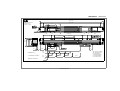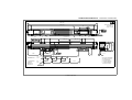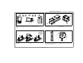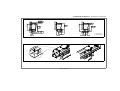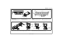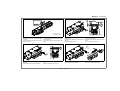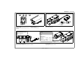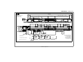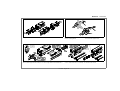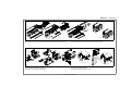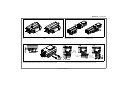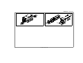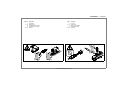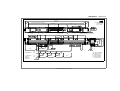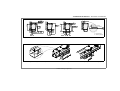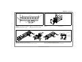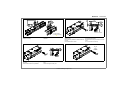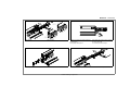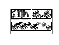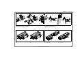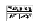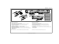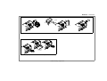
1
ENCODER LINEAL MODELO: L UNITARIA
LINEAR ENCODER MODEL: L SINGLE
Fagor Automation S. Coop.
MANUAL DE INSTALACION
INSTALLATION MANUAL
Manual Code: 14460131
Manual Version: 1201
CONTENIDOS - CONTENTS
Página
1
2-3
4
5
6-9
Contenido
Contenidos
Dimensiones
Posibilidades de montaje
Tolerancias de montaje
Montaje
DIN EN 100
Page
1
2-3
4
5
6-9
OFF
L unitaria - Page 1 / 9
Contents
Contents
Dimensions
Mounting possibilities
Mountig tolerances
Mounting
ON
DIMENSIONES - DIMENSIONS
CM + 301
mm
Tolerancing ISO 8015
ISO 2768 - m H
< 6 mm: ± 0.2 mm
30.5
CM + 240
30.5
4,75
76
7
4,75
25
0.05
0.1 G
78,5
33
n x 200
±0.15
±0.15
45
86,5
37
±0.15
A
0.3 G
±1.5
200
25
10
±1.5
51,5
25
9,5
2.5
±1.5
62
79
+2.5
-0.5
85
+2.5
-0.5
200
40
0.3 A
90
25
CM
INCREMENTAL Io
1ª Io
1st Io
20
Io CODIFICADO / CODED Io
1ª Io
1st Io
5
50
40,04
ABSOLUTA / ABSOLUTE
MODELO ESTANDAR.
50
50
40,08
80
q x 50
40,12
80
80
P=40
STANDARD MODEL.
L unitaria - Page 2 / 9
r x 80
CM = Curso de medición
CM = Measuring length
G = Guía máquina
G = Machine guideway
P = Posición absoluta
P = Absolute position
POSIBILIDADES DE MONTAJE - MOUNTING POSSIBILITIES
CM + 301
CM + 240
mm
Tolerancing ISO 8015
ISO 2768 - m H
< 6 mm: ± 0.2 mm
30.5
4,75
30.5
76
7
4,75
25
0.05
0.1 G
±0.15
33
78,5
25
85
9,5
25
109,5
+2.5
-0.5
±0.15
+2.5
-0.5
200
79
±0.15
±1.5
n x 200
200
±1.5
45
2.5
37
A
62
86,5
0.3 G
40
0.3 A
90
25
10
±1.5
CM
INCREMENTAL Io
1ª Io
1st Io
20
50
40,04
Io CODIFICADO
CODED Io
ABSOLUTA
ABSOLUTE
MODELO ESPEJO.
1ª Io
1st Io
5
50
50
40,08
80
q x 50
40,12
80
80
r x 80
P=40
MIRROR MODEL.
L unitaria - Page 3 / 9
CM = Curso de medición
CM = Measuring length
G = Guía máquina
G = Machine guideway
P = Posición absoluta
P = Absolute position
POSIBILIDADES DE MONTAJE - MOUNTING POSSIBILITIES
B
A
A
Montar con los labios de estanqueidad no
orientados a posibles fuentes de contaminación.
Mount it with the sealing lips facing away
from contaminating elements.
A: Entradas de aire.
B: Tensor del fleje.
A: Air intakes.
B: Tape tensor.
Es posible orientar la salida del conector a
ambos lados.
The connector exit may be oriented at both
ends.
Si se monta la regla verticalmente y no se
instala ningún equipo de aire, conviene quitar
el tornillo de entrada de aire inferior.
When mounting the scale vertically and no air
filter is installed, remove the bottom air intake
screw.
L unitaria - Page 4 / 9
TOLERANCIAS DE MONTAJE - MOUNTING TOLERANCES
0.1 G
0.03
62
0.5
0.1 G
79
0.5
±0.3
±1.5
0.1
0.1 G
10 ±1.5
l
15
45 ±1.5
±1.5
25
G = Guía máquina
G = Machine guideway
Posibilidades de montaje y tolerancias.
Mounting possibilities and tolerances.
Las marcas triangulares de la regla definen el inicio y el final del curso de medición.
The triangle marks of the scale indicate the beginning and end of the measuring length.
L unitaria - Page 5 / 9
MONTAJE - MOUNTING
M5
23
2.5
50
±1.5
CM + 300
M6
Aflojar los tornillos para posicionar la cabeza
en la zona de montaje.
Los soportes fijan la distancia de separación
(2.5 mm) entre la cabeza y la regla.
Loosen the screws to position the reader
head in the mounting area.
The supports set the 2.5 mm gap between
the reader head and the scale.
12 min.
95
Realizar los agujeros para amarrar la regla.
Los agujeros de los pasadores se realizarán
más tarde.
El área marcada estará libre de pintura.
Make the holes to secure the scale.
The holes for the dowel pins will be made
later.
The marked area must be free of paint.
DIN 433
M5x50
DIN 912
Pa = 5 Nm
M6
L
M6x35
DIN 912
Pa = 5 Nm
M6
DIN 555
10 min.
Premontar la regla y la cabeza lectora.
Montar todos los tornillos excepto en los extremos de la regla (ver figura).
Premount the scale and the reader head.
Mount all the screws except at both ends of the scale (see drawing).
L unitaria - Page 6 / 9
M5x(L+10)
DIN 912
Pa = 4 Nm
Ø6 H7
MONTAJE - MOUNTING
14 min.
1 aprox.
0.3 G
G = Guía máquina
G = Machine guideway
Alinear la regla.
Terminar de apretar los tornillos de la regla y
la cabeza.
La figura muestra la zona en la que se ha de
palpar con el reloj.
Align the scale.
Finish tightening the screws of the scale and
the reader head.
The drawing shows the area to be dial indicated.
DIN 7979-C 6x60 St
Mecanizar a la vez la regla y la bancada a
diámetro 6H7.
Montar los dos pasadores a ambos lados de
la regla.
No meterlos hasta el fondo.
2
Machine the scale and the bed to a diameter
of 6H7 at the same time.
Mount the two dowel pins at both ends of the
scale.
Do not insert them all the way.
DIN 433
+
M5x50
DIN 912
Pa = 5 Nm
1
Quitar los dos tornillos que trae la regla a ambos lados.
Terminar de introducir los dos pasadores.
Remove the two screws of the scale at both
ends.
Finish inserting the two dowel pins.
Montar los tornillos en los dos extremos.
Quitar los soportes de la cabeza.
L unitaria - Page 7 / 9
Mount the screws at both ends.
Remove the reader head supports.
MONTAJE - MOUNTING
<1
En ambientes muy contaminantes conviene
proteger la regla.
Utilizar juntas de estanqueidad para evitar filtraciones.
In very polluted environments, the scale
should be protected.
Use seals to prevent filtration.
Unidades de Filtro de Aire Fagor
Fagor Air Filter Units
Realizar una comprobación de la correcta
deriva a tierra de la regla.
Check for proper scale grounding.
Para IP-64
For IP-64
Modelos AI-400 Models
AI-500
1 bar
10 l/min.
Pa = 1 Nm
DIN ISO 8573-1
Tamaño de particula
Particle size
- (Class 1) - Max. 0.1µm
Punto de rocio
Dewpoint
- (Class 4) - (7 bar) 3ºC
Contenido residual de aceite
Residual oil content - (Class 1) - 0.01 mg/m³
Existe la posibilidad de presurizar la cabeza lectora y la regla para minimizar la entrada de
contaminación desde el exterior.
Fagor suministra unidades de aire expecíficas a tal efecto.
There is a possibility to pressurize the reader head and the scale to minimize contamination
from the outside.
Fagor supplies the air units for that.
L unitaria - Page 8 / 9
MONTAJE - MOUNTING
1
3
2
Control
Allen (3 mm)
La regla viene calibrada.
De todas formas, Fagor recomienda compensar mediante un Interferómetro Laser los posibles errores causados durante el montaje de la regla.
The scale is already calibrated.
However, Fagor recommends to use a Laser Interferometer to compensate for possible errors
originated while installing the scale.
2
3
Allen (3 mm)
Pa = 5 Nm
1
Tras calibrar la regla, bloquear el tensor.
After calibrating the scale, lock the tensor..
L unitaria - Page 9 / 9
NOTAS DE USUARIO - USER NOTES
NOTAS DE USUARIO - USER NOTES
NOTAS DE USUARIO - USER NOTES
FAGOR AUTOMATION S. COOP.
Bª San Andrés Nº 19
Apdo de correos 144
20500 Arrasate/Mondragón
Spain
Web: www.fagorautomation.com
Email: [email protected]
Tel.: (34) 943 719200
Fax: (34) 943 791712
ENCODER LINEAL MODELO: L MODULAR
LINEAR ENCODER MODEL: L MODULAR
Fagor Automation S. Coop.
MANUAL DE INSTALACION
INSTALLATION MANUAL
Manual Code: 14460132
Manual Version: 1201
CONTENIDOS - CONTENTS
Página
1
2-3
4
5
6 - 14
Contenido
Page
Contents
Contenidos
Dimensiones
Posibilidades de montaje
Tolerancias de montaje
Montaje
1
2-3
4
5
6 - 14
Contents
Dimensions
Mounting possibilities
Mountig tolerances
Mounting
DIN EN 100
OFF
L modular - Page 1 / 14
ON
DIMENSIONES - DIMENSIONS
CM + 301
30.5
mm
Tolerancing ISO 8015
ISO 2768 - m H
< 6 mm: ± 0.2 mm
CM + 240
1411,5
78,5
4,75
25
0.05
0.1 G
33
n x 200
±0.15
±0.15
±0.15
45
200
86,5
37
±0.15
A
0.3 G
±1.5
200
25
10
±1.5
51,5
25
9,5
2.5
±1.5
62
+2.5
-0.5
79
+2.5
-0.5
200
85
L (1268,5-1468,5-1668,5-...-2468,5)
4,75
76
7
30.5
m x 1400
40
0.3 A
90
25
CM
INCREMENTAL Io
1ª Io
1st Io
20
Io CODIFICADO / CODED Io
1ª Io
1st Io
5
50
40,04
ABSOLUTA / ABSOLUTE
MODELO ESTANDAR.
50
50
40,08
80
q x 50
40,12
80
80
P=40
STANDARD MODEL.
L modular - Page 2 / 14
r x 80
CM = Curso de medición
CM = Measuring length
G = Guía máquina
G = Machine guideway
P = Posición absoluta
P = Absolute position
DIMENSIONES - DIMENSIONS
CM + 301
CM + 240
30.5
4,75
76
7
25
0.05
0.1 G
200
±0.15
33
200
78,5
±0.15
2.5
25
9,5
25
109,5
+2.5
-0.5
±0.15
±1.5
A
±0.15
85
n x 200
200
+2.5
-0.5
45
62
37
4,75
86,5
0.3 G
mm
Tolerancing ISO 8015
ISO 2768 - m H
< 6 mm: ± 0.2 mm
1411,5
m x 1400
79
L (1268,5-1468,5-1668,5-...-2468,5)
±1.5
30.5
40
0.3 A
90
25
10
±1.5
CM
INCREMENTAL Io
1ª Io
1st Io
20
50
40,04
Io CODIFICADO
CODED Io
ABSOLUTA
ABSOLUTE
MODELO ESPEJO.
1ª Io
1st Io
5
50
50
40,08
80
q x 50
40,12
80
80
r x 80
P=40
MIRROR MODEL.
L modular - Page 3 / 14
CM = Curso de medición
CM = Measuring length
G = Guía máquina
G = Machine guideway
P = Posición absoluta
P = Absolute position
POSIBILIDADES DE MONTAJE - MOUNTING POSSIBILITIES
B
A
A
Montar co n l os labios de estanqueidad no
orientados a posibles fu entes de c ontaminación.
Mount it with the sealing lips facing away
from contaminating elements.
.
A: Entradas de aire.
B: Tensor del fleje.
A: Air intakes.
B: Tape tensor.
.
Es po sible o rientar l a s alida d el co nector a
ambos lados.
The connector exit may be oriented at both
ends.
Si se monta la regla verticalmente y n o se
instala ningún equipo de aire, conviene quitar
el tornillo de entrada de aire inferior.
When mounting the scale vertically and no air
filter is installed, remove the bottom air intake
screw.
L modular - Page 4 / 14
TOLERANCIAS DE MONTAJE - MOUNTING TOLERANCES
máx. 9.5
0.1 G
0.03
62
0.5
0.1 G
Junta entre módulos
Gasket between modules
2
79
0.5
±0.3
±1.5
0.1
0.1 G
10 ±1.5
l
45 ±1.5
15
±1.5
25
G = Guía máquina
G = Machine guideway
Posibilidades de montaje y tolerancias.
Mounting possibilities and tolerances.
Las marcas triangulares de la regla definen el inicio y el final del curso de medición.
The triangle marks of the scale indicate the beginning and end of the measuring length.
L modular - Page 5 / 14
MONTAJE - MOUNTING
CM + 300
23
50
M5
M6
Realizar los agujeros para amarrar la regla.
Los agujeros de los pasadores se realizarám
más tarde.
El área marcada estará libre de pintura.
95
Make the holes to secure the scale.
The holes for the dowel pins will be made
later.
The marked area must be free of paint.
Quitar las tapas y la cinta protectora de los
módulos.
Remove the end caps and the protective tape
of the modules.
12 min.
DIN 433
M5x50
DIN 912
Pa = 5 Nm
Montar los módulos de la regla y alinearlos.
Utilizar el calzo separador de 4 mm entre módulos.
Montar todos los tornillos excepto en los extremos de la regla (ver figura).
Mount the scale modules and lign them up.
Use the 4 mm separator wedge between modules..
Mount all the screws except at both ends of the scale (see drawing).
L modular - Page 6 / 14
Ø6 H7
MONTAJE - MOUNTING
0.03
14 min.
1 aprox.
0.3 G
DIN 7979-C 6x60 St
G = Guía máquina
G = Machine guideway
La figura muestra la zona en la que se ha de
palpar con el reloj.
The drawing shows the area to be dial
indicated.
Mecanizar a l a vez l a regla y l a b ancada a
diámetro 6H7.
Montar los dos pasadores a ambos lados de
la regla.
No meterlos hasta el fondo.
Machine the scale and the bed to a diameter
of 6H7 at the same time.
Mount the two dowel pins at both ends of the
scale.
Do not insert them all the way.
DIN 433
+
M5x50
DIN 912
Pa = 5 Nm
2
1
Quitar los dos tornillos que trae la regla a ambos lados.
Terminar de introducir los pasadores.
Remove the two screws that the scale has on
both sides.
Finish inserting the dowel pins.
Montar los tornillos en los dos extremos.
L modular - Page 7 / 14
Mount the screws at both ends.
.
MONTAJE - MOUNTING
Quitar las tapas.
Preparar el fleje.
No tocar la parte grabada.
Remove the end caps.
Prepare the tape.
Do not touch the engraved side.
El fleje se introducirá
en la ranura.
Insert the tape
into the slot.
Fleje absoluto.
Absolute tape.
1
1
En los modelos estandar introducir el fleje LO-OOO en la regla desde el módulo Mod-K-T-Li.
En los modelos espejo introducir el fleje LO-OOO-M en la regla desde el módulo Mod-K-M-Li.
2
3
In standard models insert the LO-OOO tape from the Mod-K-T-Li module.
In mirror models insert the LO-OOO-M tape from the Mod-K-M-Li module.
L modular - Page 8 / 14
MONTAJE - MOUNTING
OK
NO
2
1
OK
NO
Click
Meter el tensor y enganchar el fleje.
Tirar del tensor hacia afuera y pretensarlo manualmente mediante el tornillo hasta el tope.
Insert the tensor and engage the tape.
Pull at the tensor and tension it all the way by hand using the screw.
1º
1st
Grasa
Grease
2º
2nd
Introducir los labios uno a uno según el orden indicado.
Cortar los labios a la medida y levantarlos.
Engrasar los labios con la grasa suministrada.
Insert the lips one by one in the order shown .
Cut the lips to size and lift them up.
Lubricate the lips with the supplied grease.
L modular - Page 9 / 14
MONTAJE - MOUNTING
Loosen the packing screws of the reader
head.
Introducir la cabeza por cualquiera de los dos
extremos de la regla.
±1.5
Aflojar los tornillos del embalaje de la cabeza.
M6
L
2.5
M6x35
DIN 912
Pa = 5 Nm
Insert the reader head through any of the two
ends of the scale.
M6
DIN 555
10 min.
Fijar la cabeza lectora.
Los soportes fijan la distancia de separación (2.5 mm) entre la cabeza y la regla.
M5x(L+10)
DIN 912
Pa = 4 Nm
Secure the reader head.
The supports set the 2.5 mm gap between the reader head and the scale.
L modular - Page 10 / 14
MONTAJE - MOUNTING
Pa < 0.8 Nm
Quitar los soportes de la cabeza.
Remove the reader head supports.
Poner las tapas.
L modular - Page 11 / 14
Labios
Lips
Mount the end caps.
MONTAJE - MOUNTING
<1
En ambientes muy contaminantes conviene
proteger la regla.
Utilizar juntas de estanqueidad para evitar filtraciones.
In very polluted environments, the scale
should be protected.
Use seals to prevent filtration.
Unidades de Filtro de Aire Fagor
Fagor Air Filter Units
Realizar una comprobación de l a c orrecta
deriva a tierra de la regla.
Check for proper scale grounding.
Para IP-64
For IP-64
Modelos AI-400 Models
AI-500
1 bar
10 l/min.
Pa = 1 Nm
DIN ISO 8573-1
Tamaño de particula
Particle size
- (Class 1) - Max. 0.1µm
Punto de rocio
Dewpoint
- (Class 4) - (7 bar) 3ºC
Contenido residual de aceite
Residual oil content - (Class 1) - 0.01 mg/m³
Existe la posibilidad de presurizar la cabeza lectora y la regla para minimizar la entrada de
contaminación desde el exterior.
Fagor suministra unidades de aire expecíficas a tal efecto.
There is a possibility to pressurize the reader head and the scale to minimize contamination
from the outside.
Fagor supplies the air units for that.
L modular - Page 12 / 14
MONTAJE - MOUNTING
1
7
3
2
5
0000.000
L
4
L
5
6
3 mm Allen
0000.000
(L+90)x0.00012
(L+D+90)x0.00012
6
D
0000.000
L
Se debe ajustar el fleje con un interferómetro laser (recomendable) o bien manualmente.
Use a Laser interferometer (recommended) to adjust the tape or do it manually.
Ajustar el fleje manualmente
Adjusting the tape manually
1. Quitar el tapón que da acceso al tensor del fleje.
2. Situar la cabeza lectora en el extremo izquierdo aproximádamente y preseleccionar con el valor 0 el Visualizador.
3. Desplazar la cabeza lectora hacia el extremo derecho y anotar la lectura
mostrada por el visualizador “L”.
4. Preseleccionar en esta posición con el valor 0 el Visualizador.
5. Girar el tensor del fleje hasta que el visualizador muestre el valor obtenido mediante la formula: (L+90) x 0,00012.
6. Utilizar la fórmula (L+D+90) x 0,00012 si en el extremo izquierdo no hemos posicionado la
cabeza en el triángulo.
7. Poner el tapón.
1. Remove the cap to access the tape tensor.
2. Place the reader head approximately at the left end and preset the DRO to 0.
3. Slide the reader head towards the right end and write down the DRO reading “L”.
4. Preset the DRO to 0 in this position.
5. Turn the tape tensor until the DRO displays the value obtained with the formula:
(L+90) x 0,00012.
6. Use the formula (L+D+90) x 0.00012 if at the left end you have not positioned the reader
head in the triangle.
7. Put the cap back on.
Nota: Tanto el valor de L, como el valor obtenido, se deben expresar en milímetros.
Note: Both the L value and the one obtained must be given in mm.
L modular - Page 13 / 14
MONTAJE - MOUNTING
1
3
2
Control
Allen (3 mm)
Ajustar el fleje mediante un Interferómetro Laser
Adjust the tape with a Laser Interferometer.
2
3
Allen (3 mm)
Pa = 5 Nm
1
Tras calibrar la regla, bloquear el tensor.
After calibrating the scale, lock the tensor.
L modular - Page 14 / 14
NOTAS DE USUARIO - USER NOTES
NOTAS DE USUARIO - USER NOTES
FAGOR AUTOMATION S. COOP.
Bª San Andrés Nº 19
Apdo de correos 144
20500 Arrasate/Mondragón
Spain
Web: www.fagorautomation.com
Email: [email protected]
Tel.: (34) 943 719200
Fax: (34) 943 791712
ENCODER LINEAL MODELO: L MODULAR EXTRA LARGA
LINEAR ENCODER MODEL: L MODULAR EXTRA LONG
Fagor Automation S. Coop.
MANUAL DE INSTALACION
INSTALLATION MANUAL
Manual Code: 14460138
Manual Version: 1201
CONTENIDOS - CONTENTS
Página
1
2-3
4
5
6 - 15
Contenido
Page
Contents
Contenidos
Dimensiones
Posibilidades de montaje
Tolerancias de montaje
Montaje
1
2-3
4
5
6 - 15
Contents
Dimensions
Mounting possibilities
Mountig tolerances
Mounting
DIN EN 100
OFF
L modular extra larga - Page 1 / 15
ON
DIMENSIONES - DIMENSIONS
CM + 301
30.5
mm
Tolerancing ISO 8015
ISO 2768 - m H
< 6 mm: ± 0.2 mm
CM + 240
1411,5
76
4,75
25
0.05
0.1 G
78,5
33
n x 200
200
±0.15
±0.15
45
200
86,5
37
±0.15
A
0.3 G
±1.5
25
10
±1.5
51,5
25
9,5
±1.5
±0.15
2.5
62
+2.5
-0.5
79
+2.5
-0.5
200
85
L (1268,5-1468,5-1668,5-...-2468,5)
4,75
7
30.5
m x 1400
40
0.3 A
90
25
CM
INCREMENTAL Io
1ª Io
1st Io
20
50
40,04
Io CODIFICADO / CODED Io
ABSOLUTA / ABSOLUTE
MODELO ESTANDAR.
1ª Io
1st Io
5
50
50
40,08
80
q x 50
40,12
80
80
P=40
STANDARD MODEL.
L modular extra larga - Page 2 / 15
r x 80
CM = Curso de medición
CM = Measuring length
G = Guía máquina
G = Machine guideway
P = Posición absoluta
P = Absolute position
DIMENSIONES - DIMENSIONS
CM + 301
CM + 240
30.5
4,75
76
7
25
0.05
0.1 G
33
200
±0.15
200
78,5
±0.15
2.5
25
9,5
25
109,5
+2.5
-0.5
±0.15
40
0.3 A
90
25
10
±1.5
CM
INCREMENTAL Io
1ª Io
1st Io
20
50
40,04
Io CODIFICADO
CODED Io
ABSOLUTA
ABSOLUTE
MODELO ESPEJO.
1ª Io
1st Io
5
50
50
40,08
80
q x 50
40,12
80
80
r x 80
P=40
MIRROR MODEL.
L modular extra larga - Page 3 / 15
CM = Curso de medición
CM = Measuring length
G = Guía máquina
G = Machine guideway
P = Posición absoluta
P = Absolute position
85
A
±0.15
+2.5
-0.5
n x 200
200
62
45
±1.5
0.3 G
37
4,75
86,5
mm
Tolerancing ISO 8015
ISO 2768 - m H
< 6 mm: ± 0.2 mm
1411,5
m x 1400
79
L (1268,5-1468,5-1668,5-...-2468,5)
±1.5
30.5
POSIBILIDADES DE MONTAJE - MOUNTING POSSIBILITIES
B
A
A
Montar con los labios de estanqueidad no
orientados a posibles fuentes de contaminación.
Mount it with the sealing lips facing away
from contaminating elements.
A: Entradas de aire.
B: Tensor del fleje.
A: Air intakes.
B: Tape tensor.
Es posible orientar la salida del conector a
ambos lados.
The connector exit may be oriented at both
ends.
Si se monta la regla verticalmente y no se
instala ningún equipo de aire, conviene quitar
el tornillo de entrada de aire inferior.
When mounting the scale vertically and no air
filter is installed, remove the bottom air intake
screw.
L modular extra larga - Page 4 / 15
TOLERANCIAS DE MONTAJE - MOUNTING TOLERANCES
máx. 9.5
0.1 G
0.03
62
0.5
0.1 G
Junta entre módulos
Gasket between modules
2
79
0.5
±0.3
±1.5
0.1
0.1 G
10 ±1.5
l
15
45 ±1.5
±1.5
25
G = Guía máquina
G = Machine guideway
Posibilidades de montaje y tolerancias.
Mounting possibilities and tolerances.
Las marcas triangulares de la regla definen el inicio y el final del curso de medición.
The triangle marks of the scale indicate the beginning and end of the measuring length.
L modular extra larga - Page 5 / 15
MONTAJE - MOUNTING
CM + 300
23
50
M5
M6
Realizar los agujeros para amarrar la regla.
Los agujeros de los pasadores se realizarám
más tarde.
El área marcada estará libre de pintura.
95
Make the holes to secure the scale.
The holes for the dowel pins will be made
later.
The marked area must be free of paint.
Quitar las tapas y la cinta protectora de los
módulos.
Remove the end caps and the protective tape
of the modules.
12 min.
DIN 433
M5x50
DIN 912
Pa = 5 Nm
Montar los módulos de la regla y alinearlos.
Utilizar el calzo separador de 4 mm entre módulos.
Montar todos los tornillos excepto en los extremos de la regla (ver figura).
Mount the scale modules and lign them up.
Use the 4 mm separator wedge between modules.
Mount all the screws except at both ends of the scale (see drawing).
L modular extra larga - Page 6 / 15
Ø6 H7
MONTAJE - MOUNTING
0.03
14 min.
1 aprox.
0.3 G
DIN 7979-C 6x60 St
G = Guía máquina
G = Machine guideway
La figura muestra la zona en la que se ha de
palpar con el reloj.
The drawing shows the area to be dial
indicated
Mecanizar a la vez la regla y la bancada a
diámetro 6H7.
Montar los dos pasadores a ambos lados de
la regla.
No meterlos hasta el fondo.
Machine the scale and the bed to a diameter
of 6H7 at the same time.
Mount the two dowel pins at both ends of the
scale.
Do not insert them all the way.
DIN 433
+
M5x50
DIN912
Pa = 5 Nm
2
1
Quitar los dos tornillos que trae la regla a ambos lados.
Terminar de introducir los pasadores.
Remove the two screws of the scale at both
ends.
Finish inserting the dowel pins.
Montar los tornillos en los dos extremos.
L modular extra larga - Page 7 / 15
Mount the screws at both ends.
MONTAJE - MOUNTING
Quitar las tapas.
Remove the end caps.
Preparar el fleje.
No tocar la parte grabada.
Prepare the tape.
Do not touch the engraved side.
El fleje se introducirá
en la ranura.
Insert the tape
into the slot.
Fleje absoluto.
Absolute tape.
1
1
En los modelos estandar introducir el fleje LO-OOO en la regla desde el módulo Mod-K-T-Li.
En los modelos espejo introducir el fleje LO-OOO-M en la regla desde el módulo Mod-K-M-Li.
2
3
In standard models insert the LO-OOO tape from the Mod-K-T-Li module.
In mirror models insert the LO-OOO-M tape from the Mod-K-M-Li module.
L modular extra larga - Page 8 / 15
MONTAJE - MOUNTING
NO
OK
Estirar del fleje.
Pull at the tape..
Anotar en que número de ventana está el extremo del perfil.
En el ejemplo de la figura: 2.
Soltar el fleje.
Release the tape..
Sacar el extremo del fleje.
L modular extra larga - Page 9 / 15
Write down the window number located at
the end of the profile.
In the example of the drawing: 2.
Pull out the end of the tape.
MONTAJE - MOUNTING
2
1
Ninguna Ventana
No window
Cortar el fleje según el número de ventana
anotado anteriomente.
Cortar con las tijeras suministradas.
Contactar con Fagor / Contact Fagor
Cut the tape according to the window number
written down earlier.
Cut it with the scissors provided.
Sujetar el fleje.
Hold the tape.
OK
NO
2
1
OK
NO
Click
Meter el tensor y enganchar el fleje.
Tirar del tensor hacia afuera y pretensarlo manualmente mediante el tornillo hasta el tope.
Insert the tensor and engage the tape.
Pull at the tensor and tension it all the way by hand using the screw.
L modular extra larga - Page 10 / 15
MONTAJE - MOUNTING
1º
1st
Grasa
Grease
2º
2nd
Introducir los labios uno a uno según el orden indicado.
Cortar los labios a la medida y levantarlos.
Engrasar los labios con la grasa suministrada.
Insert the lips one by one in the order shown.
Cut the lips to size and lift them up.
Lubricate the lips with the supplied grease.
Aflojar los tornillos del embalaje de la cabeza.
Introducir la cabeza por cualquiera de los dos
extremos de la regla.
Loosen the packing screws of the reader
head.
L modular extra larga - Page 11 / 15
Insert the reader head through any of the two
ends of the scale.
±1.5
MONTAJE - MOUNTING
M6
L
2.5
M6x35
DIN 912
Pa = 5 Nm
M6
DIN 555
M5x(L+10)
DIN 912
Pa = 4 Nm
10 min.
Fijar la cabeza lectora.
Los soportes fijan la distancia de separación (2.5 mm) entre la cabeza y la regla.
Secure the reader head.
The supports set the 2.5 mm gap between the reader head and the scale.
Labios
Lips
Pa < 0.8 Nm
Quitar los soportes de la cabeza.
Remove the reader head supports.
Poner las tapas.
L modular extra larga - Page 12 / 15
Mount the end caps.
MONTAJE - MOUNTING
<1
En ambientes muy contaminantes conviene
proteger la regla.
Utilizar juntas de estanqueidad para evitar filtraciones.
In very polluted environments, the scale
should be protected.
Use seals to prevent filtration.
Unidades de Filtro de Aire Fagor
Fagor Air Filter Units
Realizar una comprobación de la correcta
deriva a tierra de la regla.
Check for proper scale grounding.
Para IP-64
For IP-64
Modelos AI-400 Models
AI-500
1 bar
10 l/min.
Pa = 1 Nm
DIN ISO 8573-1
Tamaño de particula
Particle size
- (Class 1) - Max. 0.1µm
Punto de rocio
Dewpoint
- (Class 4) - (7 bar) 3ºC
Contenido residual de aceite
Residual oil content - (Class 1) - 0.01 mg/m³
Existe la posibilidad de presurizar la cabeza lectora y la regla para minimizar la entrada de
contaminación desde el exterior.
Fagor suministra unidades de aire expecíficas a tal efecto.
There is a possibility to pressurize the reader head and the scale to minimize contamination
from the outside.
Fagor supplies the air units for that.
L modular extra larga - Page 13 / 15
MONTAJE - MOUNTING
1
7
3
L
2
5
0000.000
4
0000.000
L
5
6
3 mm Allen
(L+90)x0.00012
(L+D+90)x0.00012
6
D
0000.000
L
Se debe ajustar el fleje con un Interferómetro Laser (recomendable) o bien manualmente.
Use a Laser Interferometer (recommended) to adjust the tape or do it manually.
Ajustar el fleje manualmente
Adjusting the tape manually
1. Quitar el tapón que da acceso al tensor del fleje.
2. Situar la cabeza lectora en el extremo izquierdo aproximádamente y preseleccionar con el valor 0 el Visualizador.
3. Desplazar la cabeza lectora hacia el extremo derecho y anotar la lectura
mostrada por el visualizador “L”.
4. Preseleccionar en esta posición con el valor 0 el Visualizador.
5. Girar el tensor del fleje hasta que el visualizador muestre el valor obtenido mediante la formula: (L+90) x 0,00012.
6. Utilizar la fórmula (L+D+90) x 0,00012 si en el extremo izquierdo no hemos posicionado la
cabeza en el triángulo.
7. Poner el tapón.
1. Remove the cap to access the tape tensor.
2. Place the reader head approximately at the left end and preset the DRO to 0.
3. Slide the reader head towards the right end and write down the DRO reading “L”.
4. Preset the DRO to 0 in this position.
5. Turn the tape tensor until the DRO displays the value obtained with the formula:
(L+90) x 0,00012.
6. Use the formula (L+D+90) x 0.00012 if at the left end, you have not positioned the reader
head in the triangle.
7. Put the cap back on.
Nota: Tanto el valor de L, como el valor obtenido, se deben expresar en milímetros.
Note: Both the L value and the one obtained must be given in mm.
L modular extra larga - Page 14 / 15
MONTAJE - MOUNTING
1
3
2
Control
Allen (3 mm)
Ajustar el fleje mediante un Interferómetro Laser
Adjust the tape with a Laser Interferometer.
2
3
Allen (3 mm)
Pa = 5 Nm
1
Tras calibrar la regla, bloquear el tensor.
After calibrating the scale, lock the tensor.
L modular extra larga - Page 15 / 15
NOTAS DE USUARIO - USER NOTES
FAGOR AUTOMATION S. COOP.
Bª San Andrés Nº 19
Apdo de correos 144
20500 Arrasate/Mondragón
Spain
Web: www.fagorautomation.com
Email: [email protected]
Tel.: (34) 943 719200
Fax: (34) 943 791712