1
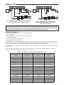
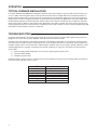
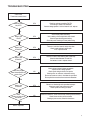
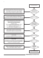
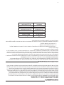
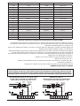
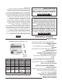
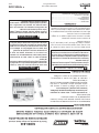
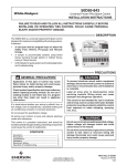
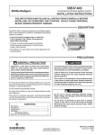
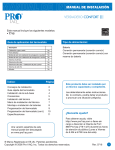
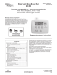
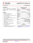
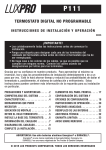
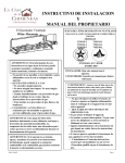
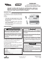
50D50-842
Universal Direct Spark Control
INSTALLATION INSTRUCTIONS
FAILURE TO READ AND FOLLOW ALL INSTRUCTIONS CAREFULLY
BEFORE INSTALLING OR OPERATING THIS CONTROL COULD CAUSE
PERSONAL INJURY AND/OR PROPERTY DAMAGE.
DESCRIPTION
The 50D50-842 is a universal replacement Direct Spark
control designed for maximum compatibility with existing
systems.
It features:
•
•
•
A card port and eight program keys to select
the Trial for Ignition Time, Retries, Prepurge and
Recycle timings.
A Jumper to accommodate systems using Direct
Sense (sensing through ignitor) or Indirect Sense
(using a Flame Sensor)
LED indicator for quick system and module diagnostics and troubleshooting.
PRECAUTIONS
! GENERAL PRECAUTION
! CAUTION
Application of this type of control may cause
flame rollout on initial startup and could cause
personal injury and/or property damage.
To prevent electrical shock and/or equipment
damage, disconnect electric power to system at
main fuse or circuit breaker box until installation
is complete.
Check product specification and cross reference
before replacing existing module. Do not use if
existing module is not listed. Use of a program
key other than listed can result in appliance
malfunction.
If in doubt about whether your wiring is millivolt, line, or
low voltage, have it inspected by a qualified heating and
air conditioning contractor or licensed electrician.
Label all wires prior to disconnection when servicing controls.Wiring errors can cause improper
and dangerous operation.
This control is not intended for use in locations
where it may come in contact with water. Suitable
protection must be provided to shield the control
from exposure to water (dripping, spraying, rain,
etc.).
Do not exceed the specification ratings.
All wiring must conform to local and national electrical
codes and ordinances.
! WARNING
This control is a precision instrument, and should be
handled carefully. Rough handling or distorting components could cause the control to malfunction.
Do not use on circuits exceeding specified voltage. Higher voltage will damage control and could
cause shock or fire hazard.
CONTENTS
Description ...................................................................
Precautions ..................................................................
Specifications ...............................................................
Installation ....................................................................
Mounting & Wiring .........................................................
Operation & Troubleshooting ........................................
1
1
2
2
3
4
Do not short out terminals on gas valve or primary
control to test. Short or incorrect wiring will damage thermostat and could cause personal injury
and/or property damage.
www.white-rodgers.com
www.emerson.com
PART NO. 37-6575E
Replaces 37-6575D
0927
SPECIFICATIONS
ELECTRICAL RATINGS:
Program Key Timing Specifications Quick Reference
Timing and Retry
Input Voltage: 18 to 30 VAC, 60 Hz
Current: 0.2 amp + MV @ 25OC
Relay Contact Ratings:
Main Valve Relay: 1.5 amp @ 25 VAC 60 Hz
Spark Output:
Gap: 0.1" - 0.2", 15kV 25Hz
Max cable length: 3ft (0.9m)
Flame Current Requirements:
Minimum current to insure flame detection: 2 µA DC*
Maximum current for non-detection: 0.2 µA DC
Maximum allowable leakage resistance: 100 M ohms
* Measured with a DC microammeter in series with the
flame probe lead
PROGRAM
KEY
(COLOR)
A (blue)
B (red)
C (green)
D (violet)
E (orange)
F (yellow)
G (blue\red)
H (red\green)
TRIAL
FOR
IGNITION
4 Sec.
4 Sec.
7 Sec.
7 Sec.
7 Sec.
7 Sec.
11 Sec.
11 Sec.
RETRIES
2
2
2
2
0
0
0
0
PREPURGE
0 Sec.
30 Sec.
0 Sec.
30 Sec.
0 Sec.
30 Sec.
0 Sec.
30 Sec.
INTER
PURGE
90 Sec.
90 Sec.
90 Sec.
90 Sec.
N/A
N/A
N/A
N/A
Program
Key
OPERATING TEMPERATURE RANGE:
-40° to 175°F (-40° to 80°C)
HUMIDITY RANGE:
To 95% relative humidity (non-condensing)
MOUNTING:
Surface mount or 4" x 4" junction box
GASES APPROVED: Natural, Manufactured, Mixed,
Liquid Petroleum, and LP Gas Air Mixtures.
Fig. 1 – Program Key installation
INSTALLATION
MOUNTING AND WIRING
! WARNING
Do not use on circuits exceeding specified voltage. Higher voltage will damage control and could
cause shock or fire hazard.
! CAUTION
To prevent electrical shock and/or equipment
damage, disconnect electric power to system at
main fuse or circuit breaker box until installation
is complete. Failure to earth ground the appliance
or reversing the neutral and hot wire connection
to the line can cause shock hazard.
Shut off main gas to heating system until installation is complete.
Route and secure all wiring as far from flame as
practical to prevent fire and/or equipment damage.
2
NOTE
Replace control as unit – no user serviceable parts.
All wiring should be installed according to local and national
electrical codes and ordinances.
The control may be mounted in any orientation on a convenient surface using two #6 x 5/8” sheet metal screws. If
desired, control can be mounted on a 4” x 4” junction box
using two #8-32 x 5/8” machine screws. The control must be
secured to an area that will experience a minimum of vibration and remain below the maximum ambient temperature
rating of 175°F. The control is approved for minimum ambient
temperatures of –40°.
Refer to the wiring diagrams and wiring table when connecting the control to other components of the system.
UL approved 105°C rated 18 gauge minimum wire is recommended for all low voltage connections. UL approved 105°C
rated 16 gauge minimum wire is recommended for all line
voltage connections.
After installation or replacement, follow appliance manufacturer’s recommended installation/service instructions to insure
proper operation.
SPARK
PROBE
Gas
Valve
MV
FLAME
Gas
Valve
FLAME
PROBE
(GND)
SPARK
GND
FLY
LEAD
TH
TR
VAL
MV
SPARK
FLY
LEAD
TH
GND
TR
MV
VAL
INSTALLATION
SPARK
PROBE
JUMPER
LINK
MV
FLAME
(GND)
Burner Ground
Burner Ground
LIMIT
CONTROLLER
(GND)
LIMIT
CONTROLLER
L1 (HOT)
(GND)
L1 (HOT)
L2
THERMOSTAT OR
CONTROLLER
ALTERNATE
LIMIT
TRANSFORMER
L2
THERMOSTAT OR
CONTROLLER
Fig. 2 – Typical hookup for White-Rodgers replacement
with separate flame sense and spark probes
ALTERNATE
LIMIT
TRANSFORMER
Fig. 3 – Typical hookup for White-Rodgers
replacement with direct flame sense through
single spark/sense probe
NOTE: Max length of spark cable should be less than 3ft (0.9m) and rated at 15kV. The cable must not run in
continuous contact with any metal surface or spark voltage is greatly reduced. Use ceramic or plastic standoff
insulators as required. Ensure burner is grounded directly to module for spark return path.
INSTALL PROGRAM KEY
The control replaces all listed models with the following features:
• direct spark ignition
• remote rod flame sense or direct flame sense through ignitor
• one or three ignition tries
• four to eleven second trial for ignition time
• pre-purge options zero or 30 seconds
Eight program keys are provided for different applications. Timings and Retries for each program key are shown in the Specifications section on page 2 of this installation manual. Choose the proper program key for the application. Install the selected
program key in the slot on the left side of the module (see figure 1) and fit the timing label on the cover.
If the module you are replacing is not listed in the table contact the manufacturer of the appliance for a recommended replacement or retrofit.
After inserting the proper program key, dispose of the remaining keys to ensure the correct key remains in the module.
If control fails to operate see troubleshooting guide for remedy.
TABLE 2. Cross Reference for Program Key and Wiring Instruction
MANUFACTURER
MODEL
KEY
WIRING
Honeywell
S8680 (generic)
Various
Fig 2 / 3
Honeywell
S87B1008
C (green)
Fig 3
Honeywell
S87B1016
G (blue\red)
Fig 3
Honeywell
S87C1006
C (green)
Fig 2
Honeywell
S87C1014
G (blue\red)
Fig 2
Honeywell
S87D1004
C (green)
Fig 2
Honeywell
S87D1012
G (blue\red)
Fig 2
Honeywell
S87J1026
H (red\green)
Fig 3
Robertshaw
DS845 780-504
C (green)
Fig 2 / 3
White-Rodgers
50D20-50
A (blue)
Fig 2 / 3
White-Rodgers
50D20-51
A (blue)
Fig 2 / 3
White-Rodgers
50D20-52
A (blue)
Fig 2 / 3
White-Rodgers
50D20-150
C (green)
Fig 2 / 3
White-Rodgers
50D20-152
C (green)
Fig 2 / 3
White-Rodgers
50D20-160
D(violet)
Fig 2 / 3
White-Rodgers
50D20-162
D(violet)
Fig 2 / 3
White-Rodgers
50D21-1
A (blue)
Fig 2 / 3
White-Rodgers
50D21-60
D(violet)
Fig 2 / 3
3
OPERATION
TYPICAL FURNACE INSTALLATION
In a typical application the 50D50-842 is designed to generate sparks and energize the gas valve and monitor the flame sensor. It is a 100% shut off design that locks out the gas valve if the burner does not light within the trial for ignition period. The
ignition sequence begins with a call for heat from the room thermostat. The thermostat applies power to the control. After prepurge interval, the valve is energized and sparks are generated for the selected trial for ignition time. If the burner lights within
the allowed period the gas valve will remain open until the call for heat is satisfied. If the burner does not light, the control will
either go into lockout or make two more ignition retries depending on the options selected. The control can be reset from lockout by cycling the thermostat to remove power for a minimum of 10 seconds. It includes a system analysis/troubleshooting LED
that indicates normal operation, lockout, or control fault.
TROUBLESHOOTING
For proper control operation, the control must be electrically connected to the gas valve and all the ignition wiring connectors
plugged in. Gas valves with an electric "ON/OFF" switch must have the switch set to "ON".
The light on the control provides a self-diagnosis indication. If the red light on the module is off continuously, the fault is likely
to be internal to the module. To make sure, interrupt the line or 24 volt thermostat power for 10 seconds, check program key installation and then restore. If the internal fault is indicated again, and flame sensor is not shorted to ground, replace the control.
A flashing light indicates a problem, most likely in the external components or wiring (see chart below). Proceed as follows:
Visual checks
1)
After the prepurge delay (if applicable) the valve opens and the ignition (sparks) starts
2)
The burner flame will light
3)
The ignition (sparks) stops
Troubleshooting the system consists of checking for these visual indications. The chart on the next page defines the proper action if any of these indications does not occur.
4
LED
Condition
Solid On
One Flash
Two Flashes
Three Flashes
Four Flashes
Five Flashes
OFF
Normal - Control ON
False flame signal
No Flame Detected
Safety Drive Fault
N/A
MV Drive Fault
No Power / Internal Fault
TROUBLESHOOTING
Call for heat,
Thermostat contacts close
Does the LED
stay OFF?
YES
Check low voltage to module (TH-TR).
If no voltage: Check Limit Switches
If correct voltage present: Unit has internal fault - replace.
NO
Does it give
1 Flash?
YES
Check flame probe and wiring
- Unit is seeing a flame signal with valve closed
Check for poor burner ground wiring
Check for partial shorting on flame probe wiring
NO
Does it give
3 Flashes?
YES
There is a fault in the internal safety relay drive
- Check supply voltage is within spec.
If it is - replace control
NO
Does it give
5 Flashes?
YES
There is an internal fault with the Main Valve relay
Check for short between TH and MV
If no external cause - replace control
NO
After Pre-purge
Does Valve operate and
sparks start?
NO
Check wiring to Valve if it does not operate
- replace Valve if voltage present
Check spark wiring for shorts if no sparks
Check sparks are at burner, not to outer casing
Ensure no breaks or cracks in insulation of spark lead
Ensure pilot flame reaches flame sensor for detection
YES
Does it give
2 Flashes?
YES
Burner has failed to light after permitted attempts
Check gas supply and pressure to valve
Check sparks and wiring as above
NO
Does
system run until call for
heat ends?
NO
Check limit switches, Check sensor leads, Check ground continuity
Check flame remains on flame sensor
Check gas jets are clear, Check for clean burn
YES
Normal Operation
5
White-Rodgers is a division
of Emerson Electric Co.
The Emerson logo is a
trademark and service mark
of Emerson Electric Co.
www.white-rodgers.com
www.emerson.com
White-Rodgers es una división de
Emerson Electric Co.
El logotipo de Emerson es una marca
comercial y una marca de servicio de
Emerson Electric Co.
www.white-rodgers.com
www.emerson.com
SOLUCIÓN DE PROBLEMAS
Llamada de calor, los contactos
del termostato se cierran
¿El LED
permanece
APAGADO?
SÍ
Verifique si el voltaje al módulo es bajo (TH-TR).
Si no hay voltaje: Verifique los interruptores limitadores
Si el voltaje es correcto: La unidad tiene una falla. Cámbiela.
NO
¿Tiene 1 intermitente?
SÍ
NO
¿Tiene 3 intermitentes?
SÍ
Verifique la sonda de llama y las conexiones
- La unidad detecta una señal de llama cuando la válvula está cerrada
Verifique que estén bien las conexiones a tierra del quemador
Verifique que no haya un cortocircuito parcial en las conexiones de la
sonda de la llama
Hay una falla en el mecanismo de relé de seguridad interno
- Verifique que el voltaje de alimentación cumpla con las
especificaciones
Si cumple, cambie el control.
NO
¿Tiene 5 intermitentes?
SÍ
NO
Después del
pre-purgado, ¿la válvula
funciona y comienzan
a generarse las
chispas?
NO
SÍ
¿Tiene 2 intermitentes?
SÍ
Hay una falla interna en el relé de la válvula principal
Verifique que no haya un cortocircuito entre TH y MV
Si no hay ninguna causa externa, cambie el control.
Verifique las conexiones a la válvula, si no funciona
- cambie la válvula si recibe voltaje
Verifique que las conexiones de encendido no estén
en cortocircuito si no hay chispas
Verifique que las chispas se produzcan en el quemador,
no en la caja externa
Asegúrese de que no haya roturas ni grietas
en el aislamiento del cable de encendido
Asegúrese de que la llama piloto llegue al detector
de llamas para su detección
El quemador no se ha encendido después de los intentos permitidos
Verifique el suministro de gas y la presión a la válvula
Verifique las chispas y las conexiones según se indica más arriba
NO
¿El sistema funciona
hasta que termina
la llamada de
calor?
NO
Verifique los interruptores limitadores, Verifique los cables del
detector, Verifique la continuidad de la conexión a tierra
Verifique que la llama permanezca en el detector de llama
Verifique que los chorros de gas estén limpios, Verifique que la
combustión sea limpia
SÍ
Funcionamiento normal
5
FUNCIONAMIENTO
INSTALACIÓN TÍPICA DE LA CALDERA
En una aplicación típica el 50D50-842 está diseñado para generar chispas y energizar la válvula de gas y monitorear el
detector de llama. Es un diseño con cierre 100% que bloquea la válvula de gas si el quemador no se enciende dentro del
período de prueba de encendido. La secuencia de encendido comienza con una llamada de calor del termostato de la
habitación. El termostato aplica alimentación al control. Después del intervalo de pre-purgado, la válvula se energiza y se
generan chispas durante el período de prueba de encendido seleccionado. Si el quemador se enciende dentro del período
permitido, la válvula de gas permanecerá abierta hasta que se satisfaga la llamada de calor. Si el quemador no se enciende,
el control se bloqueará o realizará dos intentos más de encendido según las opciones seleccionadas. El control puede
desbloquearse encendiendo y apagando el termostato para desconectar la alimentación durante un mínimo de 10 segundos.
Incluye un LED de análisis del sistema/solución de problemas que indica funcionamiento normal, bloqueo o falla del control.
SOLUCIÓN DE PROBLEMAS
Para el funcionamiento adecuado del control, éste debe estar eléctricamente conectado a la válvula de gas y todos los
conectores de los cables de encendido deben estar enchufados. Las válvulas de gas con un interruptor eléctrico de
APAGADO/ENCENDIDO deben tener el interruptor colocado en la posición ENCENDIDO.
La luz del control proporciona una indicación de autodiagnóstico. Si la luz roja del módulo está permanentemente apagada, es
probable que se trate de una falla interna del módulo. Para asegurarse, interrumpa la alimentación de línea o la
alimentación de 24 voltios al termostato durante 10 segundos, compruebe la tecla del programa y luego vuelva a conectarla.
Si vuelve a indicar una falla interna y el detector de llama no está en cortocircuito con tierra, cambie el control. Una luz intermitente indica que es muy probable que el problema se encuentre en los componentes externos o en las conexiones (vea el
siguiente cuadro). Proceda como se indica a continuación:
Verificaciones visuales
Se detiene el encendido (chispas)
3)
La llama del quemador se enciende
2)
Después del retardo de pre-purgado (si corresponde), la válvula se abre y comienza el encendido (chispas)
1)
La solución de problemas del sistema consiste en verificar estas indicaciones visuales. El cuadro de la siguiente página indica
cómo proceder si no se produce ninguna de estas indicaciones.
LED
Encendido fijo
Un intermitente
Dos intermitentes
Tres intermitentes
Cuatro intermitentes
Cinco intermitentes
APAGADO
Estado
Normal - Control
ENCENDIDO
Señal de llama falsa
No se detectó llama
Falla de mecanismo de
seguridad
N/A
Falla del mecanismo MV
No hay alimentación /
Falla interna
4
INSTALACIÓN
MV
VAL
TR
TH
GND
CABLE
FLY
ENCENDIDO
MV
VAL
TR
TH
GND
SONDA
DE ENCENDIDO
Válvula
de gas
MV
LLAMA
SONDA
DE LLAMA
(GND)
Válvula
de gas
CABLE
FLY
ENCENDIDO
SONDA
DE ENCENDIDO
PUENTE
MV
LLAMA
(GND)
Tierra del quemador
Tierra del quemador
CONTROLADOR
DE LÍMITE
(GND)
CONTROLADOR
DE LÍMITE
L1 (VIVO)
(GND)
L1 (VIVO)
L2
TERMOSTATO O
CONTROLADOR
LÍMITE
ALTERNO
L2
TRANSFORMADOR
TERMOSTATO O
CONTROLADOR
Fig. 2 – Conexión típica para el repuesto de
White-Rodgers con detección de llama separada
y sondas de encendido
LÍMITE
ALTERNO
TRANSFORMADOR
Fig. 3 – Conexión típica para el repuesto de
White-Rodgers con detección de llama directa a
través de una sola sonda de encendido/detección
NOTA: la longitud del cable de encendido debe ser de 3 pies (0.9 m) como máximo, con un voltaje nominal de 15 kV. El cable
no debe estar en contacto permanente con ninguna superficie metálica ya que esto podría reducir considerablemente el
voltaje de encendido. Utilice aisladores distanciadores de cerámica o plástico según sea necesario. Asegúrese de que
el quemador esté conectado a tierra directamente al módulo para el circuito de retorno de encendido.
INSTALE LA TECLA DE PROGRAMA
El control reemplaza todos los modelos incluidos en la lista con las siguientes características:
• encendido de chispa directo
• detección de llama con varilla remota o detección de llama directa a través del dispositivo de encendido
• uno o tres intentos de encendido
• tiempos de segundo intento de encendido de cuatro a once segundos
• opciones de pre-purgado cero o 30 segundos
Se suministran ocho teclas de programa para diferentes aplicaciones. Los tiempos y el número de reintentos para cada tecla
de programa se indican en la sección Especificaciones, en la página 2 de este manual de instalación. Elija la tecla de
programa adecuada para la aplicación. Instale la tecla de programa seleccionada en la ranura del lado izquierdo del módulo
(vea la figura 1) y coloque la etiqueta de tiempo sobre la cubierta.
Si el módulo que desea cambiar no está incluido en la tabla, póngase en contacto con el fabricante del equipo para consultar
por un repuesto o reacondicionamiento recomendado.
Después de insertar la tecla de programa adecuada, deseche las teclas restantes para asegurarse de que quede la tecla
correcta en el módulo. Si el control no funciona correctamente, vea cómo proceder en la guía de solución de problemas.
TABLA 2. Referencia cruzada de teclas de programa e instrucciones de conexión
FABRICANTE
MODELO
Honeywell
TECLA
S8680 (genérica)
Honeywell
CONEXIÓN
Varios
S87B1008
Honeywell
Fig. 2 / 3
C (verde)
S87B1016
Honeywell
Fig 3
G (azul\rojo)
S87C1006
Honeywell
Fig 3
C (verde)
S87C1014
Honeywell
Fig 2
G (azul\rojo)
S87D1004
Honeywell
Fig 2
C (verde)
S87D1012
Honeywell
Fig 2
G (azul\rojo)
S87J1026
Robertshaw
Fig 2
H (rojo\verde)
DS845 780-504
White-Rodgers
Fig 3
C (verde)
50D20-50
White-Rodgers
Fig 2 / 3
A (azul)
50D20-51
White-Rodgers
Fig 2 / 3
A (azul)
50D20-52
White-Rodgers
Fig 2 / 3
A (azul)
50D20-150
White-Rodgers
Fig 2 / 3
C (verde)
50D20-152
White-Rodgers
Fig 2 / 3
C (verde)
50D20-160
White-Rodgers
Fig 2 / 3
D(violeta)
50D20-162
White-Rodgers
Fig 2 / 3
D(violeta)
50D21-1
White-Rodgers
Fig 2 / 3
A (azul)
50D21-60
Fig 2 / 3
D(violeta)
Fig 2 / 3
3
ESPECIFICACIONES
CARACTERÍSTICAS ELÉCTRICAS:
Voltaje de entrada: 18 a 30 VCA, 60 Hz
Corriente: 0.2 amp + MV a 25º C
Características de contacto de los relés:
Relé de válvula principal: 1.5 amp a 25 VCA 60 Hz
Salida de encendido:
Espacio: 0.1 pulg. - 0.2 pulg., 15 kV 25 Hz
Longitud de cable máxima: 3 pies (0.9 m)
Requisitos de corriente de llama:
Corriente mínima para asegurar la detección de la
llama: 2 µA CC*
Corriente máxima para la no detección: 0.2 µA CC
Resistencia a fugas máxima permitida: 100 M
ohmios
* Medida con un microamperímetro de CC en serie
con el electrodo de sonda de llama
Especificaciones de tiempos de las teclas de programa
Referencia rápida
Tiempos y reintento
TECLA DE
PRUEBA
PROGRAMA
DE
REPREENTRE
(COLOR)
ENCENDIDO INTENTOS PURGADOPURGADOS
A (azul)
4 Seg.
2
0 Seg.
90 Seg.
B (roja)
4 Seg.
2
30 Seg.
90 Seg.
C (verde)
7 Seg.
2
0 Seg.
90 Seg.
D (violeta)
7 Seg.
2
30 Seg.
90 Seg.
E (anaranjada)
7 Seg.
0
0 Seg.
N/A
F (amarilla)
7 Seg.
0
30 Seg.
N/A
G (azul\rojo)
11 Seg.
0
0 Seg.
N/A
H (rojo\verde)
11 Seg.
0
30 Seg.
N/A
Tecla de
programa
RANGO DE TEMPERATURA OPERATIVA:
-40° a 175°F (-40° a 80°C)
RANGO DE HUMEDAD:
Hasta 95% de humedad relativa (sin condensación)
SOPORTE:
Soporte de superficie o caja de conexiones de 4
pulg. x 4 pulg
GASES APROBADOS: natural, fabricado, mixto, gas licuado de petróleo (GLP) y mezclas de aire y GLP.
Fig. 1 – Instalación de la tecla de programa
INSTALACIÓN
Todas las conexiones eléctricas deben realizarse conforme a
los códigos y reglamentaciones locales y nacionales.
Para evitar descargas eléctricas y/o daños al
equipo, desconecte la alimentación eléctrica en
la caja de fusibles o disyuntores principal hasta
que haya finalizado la instalación del sistema.
Si no se conecta a tierra el equipo o se invierte la
conexión del cable neutro y el vivo a la línea pueden
producirse riesgos de descarga eléctrica.
Cambie el control entero en caso de ser necesario.
No contiene piezas que puedan ser reparadas por el usuario.
! ¡PRECAUCIÓN!
NOTA
MONTAJE Y CONEXIONES
Cierre la alimentación de gas principal al sistema de
calefacción hasta haber terminado la instalación.
Pase y fije todos los cables lo más lejos posible de la
llama para evitar incendios y/o daños al equipo.
! ¡ADVERTENCIA!
No utilizar en circuitos que excedan el voltaje
especificado ya que los voltajes más altos
dañarán el control y pueden causar riesgos de
electrocución o incendio.
El control puede montarse con cualquier orientación sobre
una superficie conveniente usando dos tornillos autorroscantes calibre 6 x 5/8 pulg. Si lo desea, el control puede montarse sobre una caja de conexiones de 4 pulg. x 4 pulg. usando
dos tornillos mecánicos calibre 8-32 x 5/8 pulg.
El control debe fijarse en un lugar que esté sujeto a un
mínimo de vibraciones y que se mantenga por debajo de
la temperatura ambiente nominal de 175°F. El control está
aprobado para temperaturas ambientes mínimas de –40°.
Refiérase a los diagramas y a la tabla de conexiones para
conectar el control a otros componentes del sistema.
Para todas las conexiones de bajo voltaje se recomienda
utilizar cables calibre 18 como mínimo aptos para 105°C y
aprobados por las normas UL. Para todas las conexiones de
voltaje de línea se recomienda utilizar cables calibre 16 como
mínimo aptos para 105°C y aprobados por las normas UL.
Una vez finalizada la instalación o el reemplazo, siga las
instrucciones de instalación/mantenimiento recomendadas
por el fabricante del equipo para asegurar su correcto
funcionamiento.
2
50D50-842
Control de encendido por chispa directa universal
INSTRUCCIONES DE INSTALACIÓN
EL NO LEER Y SEGUIR CON CUIDADO TODAS LAS INSTRUCCIONES
ANTES DE INSTALAR O UTILIZAR ESTE CONTROL PODRÍA CAUSAR
LESIONES PERSONALES Y/O DAÑOS MATERIALES.
DESCRIPCIÓN
El 50D50-842 es un control de encendido por chispa directa
universal de repuesto diseñado para ofrecer la máxima
compatibilidad con los sistemas existentes.
Este control incluye:
•
•
•
Un puerto de tarjeta y ocho teclas de programa
para seleccionar el tiempo de prueba de encendido,
reintentos, pre-purgado y reinicio de ciclo.
Un puente para adaptar el control a sistemas que
utilizan detección directa (detección a través del
dispositivo de encendido) o detección indirecta (usando
un detector de llama).
Indicador de LED para facilitar el diagnóstico y
solución de problemas en el sistema y el módulo.
PRECAUCIONES
Para evitar descargas eléctricas y/o daños al equipo,
desconecte la alimentación eléctrica en la caja de fusibles o
disyuntores principal hasta que haya finalizado la instalación
del sistema.
La aplicación de este tipo de control podría causar llamaradas
al poner en marcha el equipo y producir lesiones personales
y/o daños materiales.
! ¡PRECAUCIÓN!
! ¡PRECAUCIÓN GENERAL!
Verifique las especificaciones del producto y las referencias
cruzadas antes de cambiar el módulo existente. No lo utilice
si el módulo existente no está incluido en la lista. El uso de
una tecla de programa que no esté incluida en la lista puede
producir el mal funcionamiento del equipo.
Si tiene dudas acerca de si su conexión eléctrica es milivoltio, de
línea o de bajo voltaje, hágala inspeccionar por un técnico especializado en equipos de calefacción y aire acondicionado o por un
electricista autorizado.
Identifique todos los cables antes de desconectarlos
cuando realice tareas de mantenimiento en los controles.
Los errores en las conexiones pueden dar lugar al
funcionamiento incorrecto y peligroso del dispositivo.
Este control no está diseñado para ser utilizado en lugares en los que puede entrar en contacto con agua. Debe
proporcionarse una protección adecuada para proteger el
control de su exposición al agua (goteo, rociado, lluvia, etc.).
No exceda los valores nominales especificados.
Todas las conexiones eléctricas deben cumplir con los códigos y
reglamentaciones locales y nacionales.
Este control es un instrumento de precisión y debe manipularse con
cuidado. La manipulación descuidada o la distorsión de los componentes podrían hacer que el control no funcionara correctamente.
CONTENIDO
Descripción ..................................................................
Precauciones ...............................................................
Especificaciones ..........................................................
Instalación ....................................................................
Montaje y Conexiones ..................................................
Funcionamiento y Solución de problemas ...................
1
1
2
2
2
4
! ¡ADVERTENCIA!
No utilizar en circuitos que excedan el voltaje especificado
ya que los voltajes más altos dañarán el control y pueden
causar riesgos de electrocución o incendio.
No cortocircuite las terminales de la válvula de gas ni del
control principal para probarlos. Un cortocircuito o una
conexión incorrecta dañará el termostato y podría causar
lesiones personales y/o daños materiales.
www.white-rodgers.com
www.emerson.com
N° DE PIEZA 37-6575E
Reemplaza 37-6575D
0927