1
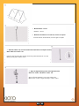
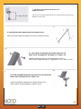
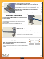
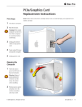
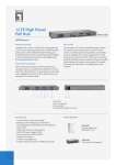
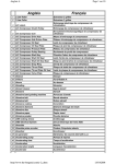
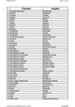
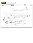
SYSTEM INSTALLATION MANUAL
MANUAL DE INSTALACIÓN
EN ES
Measuring Tape
Cinta métrica
Drill
Taladro
Ø 8 mm twist drill (wood)
Broca espiral Ø 8 mm (para madera)
Hex spanner (13,19,24,27 mm)
Llave española (13,19,24,27 mm)
Ø 14 mm stone drill (brick)
Broca para piedra
Ø14 mm (ladrillo)
Angle grinder
Amoladora angular
Ratchet
Matraca
1
EN ES
Part No. 260054
Angle Mounting ø13/19
Ángulo de Montaje ø13/19
Part No. 300004
Panel Mounting profile 3.22 m
Perfil Montaje de Panel 3.22 m
Part No. 720013
Hexagonal Nut M8x30 A2
Tuerca Hexagonal M8x30 A2
Part No. 320000
Alu-Angle 1.5x0.25” 0.7 m
Ángulo-Al 38.1x63.5 mm 0.7 m
Part No. 720009
Connector 8000 M8x25
Conector 800 M8x25
Part No. 720010
Wahser M8 A2ø24/ø8.4
Roldana M8 A2ø24/ø8.4
Part No. 320002
Alu-Angle 1.5x0.25” 1.97 m
Ángulo-Al 38.1x63.5 mm 1.97 m
Part No. 720003
Hexagonal Bolt 8x12 mm galvanized
Tornillo 8x12 mm galvanizado
Part No. 720011
Hamerhead bolt M8x25 A2
Tornillo cabeza de martillo M8x25 A2
2
EN ES
Total Lenght
Longitud Total
Atachment Points
Puntos de Fijación
2
3
5
206 cm
316 cm
436 cm
2
6
646 cm
2
Collectors
Colectores
.
.
.....Atachment Points
.....Puntos de Fijación
3
EN ES
1: Measurement C = 185 cm
Medida C = 185 cm
2: Drill holes in foundation / wood ø8 mm, concrete as required
Barrenar el fondo / madera ø8 mm, concreto según se requiera
3: Attach the rubber seal, screw it in and then fasten (minimum screw depth >100 mm)
Order: rubber seal - washer - nut
Levantar la junta de goma y fijar después de atornillar (profundidad mínima >100 mm)
Órden: junta de goma - roldana - tuerca
4: Align the Angle Mounting at the same height and fasten.
Order: nut - washer - attachment - washer - nut.
Ajustar el Ángulo de Montaje a a una altura común y fijar.
Órden: tuerca - roldana - ángulo de montaje - roldana - tuerca.
4
EN ES
5: Cut off any excess length from the brench screw.
(MaB D= max. 45 mm).
Cortar el exceso de longitud del tornillo de rosca combinada (tornillo de prisionero).
(Medida D= máx. 45 mm).
6: Attach the first Alu-Angle triangle as described in 6a-6c.
Montar el primer triángulo de Ángulos de Al como se describe en 6a-6c
6a: Screw the 0.7 m Alu-Angle into the Alu-Angle 1.97 m A
Order: screw - Alu-Amgle 0.7 - Alu-Angle 1.97 - washer - nut
Atornillar el Ángulo de Al 0.7 m con el Ángulo de Al 1.97 m A
Órder: tornillo - Ángulo de Al 0.7 m - Ángulo de Al 1.97 m - roldana - tuerca.
6b: Screw Angle Mounting to the Alu-Angle 1.97 m on the front B.
Order: screw - Alu-Angle 1.97 m - washer - nut.
Atornillar el Ángulo de Montaje con el Ángulo de Al 0.7 m B.
Órder: tornillo - Ángulo de Montaje - roldana - tuerca.
5
EN ES
6c) Screw the Angle Mounting to the back of the Alu-Angle 0.7 m C
Order: screw - Angle Mounting - Alu-Angle 0.7 - washer - nut.
Atornillar el Ángulo de Montaje a la parte de atrás del Ángulo de Al 0.7 m C
Órden: tornillo - Ángulo de Montaje - Ángulo de Al 0.7 m - roldana - tuerca.
6d: Attach the second mounting triangle as described in 6 c.
Montar el segundo triángulo de montaje como se describe en 6 c.
7: Slit the Panel Mounting Profile into the lower groove of the Alu-Angle 1.97 m
and screw it using a hammer head screw, washer and nut.
Sequence: Panel Mounting Profile - screw - Alu-Angle 1.97 - washer - nut.
Montar el Perfil de Montaje de Panel en el tope del barreno bajo
de el Ángulo de Al 1.97 m usando un tornillo de cabeza de martillo, tuerca y roldana.
Secuencia: Perfil de Montaje de Panel - tornillo - Ángulo de Al - roldana - tuerca.
8: With help from another person, carry and mount the Panel into the high slot of
the Panel Mounting Profile as shown.
Con ayuda de otra persona, cargar y montar el Panel dentro de la ranura alta de el Perfil
de Montaje de Panel como se muestra en la figura.
6
EN ES
9: Slit the Panel Mounting Profile into the upper side of the Panel, press it and scre it to
the Alu-Angle 1.97 m using a screw, washer and nut.
Sequence: Panel Mounting Profile - Panel - screw - Alu-Angle 1.97 - washer - nut.
Montar el Perfil de Montaje de Panel en la parte alta del Panel, presionarlo y fijarlo en el Ángulo
de Al 1.97 m usando usando un tornillo, tuerca y roldana.
Secuencia: Perfil de Montaje de Panel - Panel - tornillo - Ángulo de Al - roldana - tuerca.
Warning: Upper and lower Panel Mounting Profiles must be perfectly straight
and parallel to another!
Atención: Los Perfiles de Montaje de Panel tienen que estar perfectamente rectos
y paralelos ente si!
Extension Kit - Kit de Extensión
10)
10: Insert the following Panel Mounting Profile (upper & lower) and atach them using
the Connector 800 M8x25
Order: Panel Mounting Profile -Connecotr 800 M8x25 - washer - nut.
Insertar el Perfil de Montaje de Panel siguiente (arriba y abajo) y sujetar mediante la
el Conector 800 M8x25
Orden: Perfil de Montaje de Panel - Conector 800 M8x25 - roldana - tuerca.
10a)
The Connector M8x25 must join both Panel Mounting Profiles by the
middle as shown on 10a.
*For an extension of 3+ a third triangle is not requiered.
El Conector M8x25 debe unir ambos Perfiles de Montaje de Panel por la mitad, como
se muestra en 10a.
*Para extensiones de 3+ un tercer triángulo no es requerido.
10: Mount the next Panel by repeating steps 8 and 9 and attach them
by a distance of 45 mm.
Notice: Before mounting another panel, the cutting ring screw connection must
first be moved onto the connection!
Montar el sigiente de Panel repitiendo los pasos 8 y 9 y colocarlos mediante una distancia
de 45 mm.
Indicación: Antes de montar otros colectores, previamente debe empujarse en cada caso
el racor de anillo cortante en la conexión!
7
EN ES
11)
11: Screw the Panel collectors into place with the proper
torque (cutting ring screw connections Ø22 mm)
Unir los Paneles colectores con el par de giro adecuado
(racores de anillo cortante Ø22 mm
KIOTO Clear Energy S.A. de C.V.
Carretera El Verde-El Castillo No. 2000 Col. Las Pintas, El Salto
Jalisco CP 45680 Tel. (+52) 333 2845230
[email protected] / www.kioto.com
8
EN ES