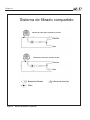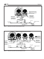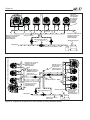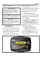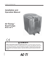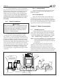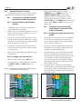
1
Datos de instalación y operación Manual de instalación y operación Air Energy™ Bombas de calor Modelo AE-Ti PELIGRO H3007600- RIESGO DE ELECTROCHOQUE O ELECTROCUCIÓN. La fuente de alimentación para este producto debe ser instalada por un electricista licenciado o certificado conforme a los códigos y ordenanzas de aplicación nacional y local. La instalación inadecuada implica un peligro eléctrico que puede resultar en muerte o lesión grave a los usuarios de piscinas o spa, instaladores u otras personas debido a electrochoque y también puede causar daño a la propiedad. Lea y siga las instrucciones específicas dentro de este manual. Página 1 Índice Sección 1. Información general ..................5 1.1 Introducción ........................................................ 5 1.2 Información al consumidor y seguridad .............. 5 1.2.1 Reglas de seguridad para Spa/Jacuzzi ....... 5 1.2.2 Consejos de ahorro de energía en las piscinas de natación .................................... 6 1.3 Garantía .............................................................. 6 1.4 Códigos y estándares ......................................... 6 1.5 Asistencia técnica ............................................... 7 1.6 Materiales necesarios para la instalación ........... 7 1.6.1 Materiales para todas las instalaciones ....... 7 1.6.2 Materiales recomendados para las instalaciones ................................................ 7 1.7 Especificaciones ................................................. 7 1.7.1 Especificaciones generales ........................ 7 1.7.2 Dimensiones ................................................ 7 1.7.3 Especificaciones técnicas ............................ 8 Sección 2. Instrucciones de instalación ....9 2.1 Información general ............................................ 9 2.2 Requerimientos de ubicación ............................. 9 2.2.1 Introducción ................................................. 9 2.2.2 Espacio ........................................................ 9 2.2.3 Plataforma del equipo .................................. 9 2.2.4 Instalaciones a cubierto ............................... 9 2.2.4.1 Condensación y drenaje ........................ 9 2.2.5 Instalaciones al aire libre ........................... 10 2.2.5.1 Rociadores de césped ......................... 10 2.2.5.2 Desagüe de techo ................................ 10 Sección 3. Conexiones de agua................10 3.1. Disposición de plomería ................................... 10 3.2 Conexiones de agua en la bomba de calor ...... 11 3.3 Instalación de la válvula de verificación............ 11 3.4 Válvula de control de flujo automática .............. 11 3.5 Disposiciones del sistema de filtración ............. 14 3.5.1 Sistema de filtración compartido ................ 14 3.5.2 Sistema de filtración independiente ........... 14 3.6 Instalación de unidad múltiple .......................... 14 3.6.1 Combinación de bomba de calor y calentador ............................................... 14 3.6.2 Conexiones de bombas de calor múltiples . 14 Sección 4. Conexiones eléctricas.............17 4.1 4.2 4.3 4.4 4.5 Información general .......................................... 17 Encendido principal .......................................... 17 Conexión (conexión a tierra)............................. 17 Conexión de la bomba (Función de mantenimiento de temperatura)........................ 17 Controles remotos opcionales .......................... 22 4.5.1 Conexión a un selector remoto POOL-OFFSPA (Conexión de 3 cables) ...................... 22 4.5.1.1 Instalación el Selector remoto POOL-OFF-SPA................................... 22 4.5.1.2 Configuración el panel de control ........ 22 4.5.2 Conexión a un sistema de control AquaLink RS o TERMOSTATO REMOTO (conexión de dos alambres)....................... 22 4.5.2.1 Configuración el sistema de control AquaLink RS .............................................. 22 4.5.2.2 Instalación del TERMOSTATO REMOTO ............................................. 23 4.5.2.3 Configuración el panel de control ........ 23 Sección 5. Operación .................................24 5.1 Precauciones para el encendido inicial ............ 24 5.2 Operación del controlador ................................ 24 5.2.1 Modo Off .................................................... 24 5.2.2 Modo Pool (piscina) - (Calor normal) ......... 24 5.2.3 Modo Pool (piscina) - (Mantenimiento de calor opcional)............................................ 25 5.2.4 Modo Spa - (Calor normal) ........................ 25 5.2.5 Modo Spa - (Mantenimiento del calor opcional)............................................ 25 5.3 Funciones de operación de unidades con el Enfriador opcional ............................................. 25 5.3.1 Modo piscina - (frío normal) ....................... 25 5.3.2 Modo piscina - (Mantenimiento de frío opcional) .............................................. 25 5.3.3 Modo Spa - (Mantenimiento de frío opcional) .............................................. 25 5.4 Opciones de configuración del usuario............. 26 5.4.1 Configuración de idioma ............................ 26 5.4.2 Configuración de escala de temperatura ... 26 5.4.3 Configuración de temporizador de spa ...... 26 Configuración de la luz de la pantalla.... 26 5.4.4 5.5 Bloqueo del valor de consigna.......................... 27 5.6 Ajuste del interruptor de presión de agua ......... 27 Sección 6. Mantenimiento general ...........28 6.1 Química del agua.............................................. 28 6.2 Preparación para el invierno ............................. 28 6.3 Encendido de primavera ................................... 28 6.4 Inspección y operaciones de servicio ............... 28 6.4.1 Inspección del propietario .......................... 28 6.4.2 Inspección profesional ............................... 29 Sección 7. Mantenimiento y servicio profesional ...............................30 7.1 7.2 Diseño de la bomba de calor ............................ 30 Componentes de la bomba de calor y las formas de operarlos......................... 30 Página 2 Índice (Continuación) 7.3 Opciones de configuración para el servicio ...... 30 7.3.1 Mantenimiento de la temperatura .............. 30 7.3.2 Mantenimiento de demora de temperatura................................................ 30 7.3.3 Remoto ...................................................... 31 7.3.4 Selección Descongelamiento..................... 31 7.3.5 Modo de prueba ......................................... 31 7.3.6 Cargar configuración de fábrica ................. 31 7.3.7 Calibración de la temperatura de la bobina 31 7.3.8 Calibración de la temperatura del agua ..... 32 7.3.9 Diferencial de la temperatura del agua ...... 32 7.3.10 Retraso al arranque ................................... 32 Sección 8. Solución de problemas ...........33 8.1 8.2 Guía de Solución de problemas ....................... 33 Diagnósticos ..................................................... 34 Sección 9. Repuestos ................................36 9.1 9.2 9.3 Información para hacer pedidos ....................... 36 Lista de repuestos de la bomba de calor Air Energy™ modelo AE-Ti............................... 36 Vista ampliada de la bomba de calor Air Energy™ modelo AE-Ti............................... 37 Garantía .................................................... Tapa trasera Figuras y Tablas Figura 1. Figura 2. Figura 3. Figura 4. Figura 5. Figura 6. Figura 7. Figura 8. Figura 9. Figura 10. Figura 11. Figura 12. Figura 13. Figura 14. Figura 15. Figura 16a. Figura 16b. Figura 17. Figura 18 Figura 19. Dimensiones de la bomba de calor AE-Ti ..8 Disposición de plomería estándar, a cubierto .................................................10 Disposición de plomería estándar ............ 11 Sistema de filtrado compartido ................12 Sistema de bomba dual (Sistemas de filtrado independientes que comparten una bomba de calor) ................................13 Plomería para combinación de sistemas de calentamiento ......................14 Disposición de plomería de dos bombas de calor ......................................15 Disposición de plomería de cuatro bombas de calor ......................................15 Disposición de plomería de seis bombas de calor ......................................16 Disposición de plomería de ocho bombas de calor (cabezales duales) .......16 Diagrama de cableado de alimentación de energía monofásica AE-Ti ...................18 Diagrama de cableado de alimentación de energía trifásica AE-Ti .........................19 Definiciones de símbolos del diagrama de cableado eléctrico ...............................20 Ejemplo de cableado de la función Mantener temperatura al reloj ..................21 Vista frontal de la bomba de calor AE-Ti ..21 Conexión Pool-Off-Spa remota (Conexión de 3 cables) .............................................22 Conexión AquaLink RS o THERMOSTATO REMOTO (Conexión de 2 cables) ...........22 Cableado AquaLink RS a bomba de calor/ AE-Ti enfriador ...............................23 Panel de control principal .........................24 Preparación para el invierno de la bomba de calor AE-Ti...............................29 Figura 20. Vista general del funcionamiento de la bomba de calor ...............................30 Figura 21. Vista ampliada de la bomba de calor Air Energy™ AE-Ti .....................37 Tabla 1. Tabla 2. Tabla 3. Tabla 4. Tabla 5. Tabla 6. Especificaciones técnicas de la bomba de calor AE-Ti ............................8 Espacios libres para la bomba de calor .....9 Rangos de agentes químicos el agua ......28 Guía de solución de problemas para la bomba de calor ....................................33 Condición de diagnóstico de averías de la bomba de calor ...................34 Datos técnicos de referencia para la solución de problemas .................35 DECLARATION OF CONFORMITY Organization: Jandy Pool Products, Inc. Located at: 6000 Condor Drive Moorpark, CA 93021 USA Declare that the products identified below: Product Description: Electric Swimming Pool & Spa Heat Pumps; “AE-Ti” Series Model Number: AE200Ti AE400Ti AE300Ti AE500Ti COMPLY WITH THE RELEVANT ESSENTIAL REQUIREMENTS OF THE FOLLOWING EUROPEAN DIRECTIVES: LOW VOLTAGE DIRECTIVE (LVD) -- 73/23/EEC, AS AMENDED BY COUNCIL DIRECTIVE 93/68/EEC; ELECTROMAGNETIC COMPATIBILITY (EMC) DIRECTIVE – 89/336/EEC; THE PRODUCTS ARE DESIGNED AND MANUFACTURED IN ACCORDANCE WITH THE RELEVANT REQUIREMENTS OF THE ABOVE REFERENCED DIRECTIVES AND ALSO IN ACCORDANCE WITH THE RELEVANT REQUIREMENTS OF: Standards: IEC 60335-1 & IEC 60335-2-40; EN61000 Declared by: _______________________________ Signature Shajee R. Siddiqui________________ Name Director, Product Safety & Compliance Title/Position D.O.C AE-Ti 05-06 Página 5 Sección 1. Información general 1.1 Introducción Este manual provee instrucciones de instalación y operación para las bombas de calor Air Energy™ modelos AE-Ti. Lea todas las instrucciones de instalación y operación antes de realizar la instalación. Consulte con Air Energy™ si tiene preguntas acerca de este equipo. Para obtener más copias de este manual, comuníquese al +1-707-776-8200 ext. 237. A continuación se encuentra la dirección de Air Energy™: 2735 NW 63rd Court. Fort Lauderdale, FL USA 33309 La bomba de calor AE-Ti obtiene energía de una fuente externa y provee un sistema dual electrónico con control de termostato para la combinación de piscina/spa o calentamiento previo. Esta bomba de calor está específicamente diseñada para calentar piscinas de natación y spas. No utilizar como calentador de servicio general. Consulte a su distribuidor sobre los productos Air Energy™ adecuados para estas aplicaciones. NOTA Las piscinas de natación y los spas incluyen sistemas que utilizan unidades generadoras de agua salada y clorinada, como el generador electrónico de cloro AquaPure. Por favor, asegúrese de que la sal contenida en la piscina/spa no exceda las 4000 ppm y de que la tasa de flujo/medida del caudal de agua se encuentre entre los 225-300 lpm. 1.2 Información al consumidor y seguridad La serie AE-Ti de bombas de calor está diseñada y fabricada para proveer muchos años de servicio confiable y seguro si son instaladas, operadas y mantenidas según la información de este manual y los códigos de instalación a los que se hace referencia en las siguientes secciones. En todo el manual, las advertencias de seguridad y precaución están identificadas con el símbolo “ ”. Asegúrese de leer y cumplir con todas las advertencias y precauciones. 1.2.1 Reglas de seguridad para Spa/jacuzzi ADVERTENCIA La Comisión de seguridad de los productos de consumo de los Estados Unidos advierte que las temperaturas elevadas pueden ser peligrosas. Consulte las instrucciones de operación e instalación del calentador para obtener las pautas de temperatura de agua antes de configurar la temperatura. ADVERTENCIA Las siguientes “Reglas de seguridad para jacuzzis” recomendadas por la Comisión de seguridad de los productos de consumo de los Estados Unidos, deben cumplirse al utilizar el spa. 1. ATENCIÓN Un instalador o un proveedor de servicios capacitado debe realizar la instalación y el mantenimiento. 2. Al instalador: Un instalador o un proveedor de servicios capacitado debe realizar la instalación y el mantenimiento. 3. Al usuario Este manual contiene información importante que le ayudará a operar y mantener la bomba de calor. Consérvelo para utilizarlo como referencia en el futuro. 4. El agua del Spa o jacuzzi nunca debe exceder los 104°F (40°C). Se considera cien grados Fahrenheit [100°F (38°C)] una temperatura segura para un adulto saludable. Se recomienda tener especial precaución con los niños. Consumir bebidas alcohólicas antes o durante el uso del spa o jacuzzi puede producir somnolencia con la posibilidad de pérdida del conocimiento, y de forma consecuente resultar en ahogamiento. Nota para mujeres embarazadas Mojarse en agua que supera los 102°F (38.5°C) puede provocar daño al feto durante los primeros tres meses de embarazo (que puede resultar en el nacimiento de un niño con daño cerebral o deforme). Si las mujeres embarazadas utilizarán un spa o jacuzzi, deben asegurarse de que la temperatura del agua se encuentre como máximo por debajo de los 100°F (38°C). La temperatura del agua siempre debe ser verificada con un termómetro preciso antes de ingresar al spa o jacuzzi. Los controles de temperatura puede variar como máximo en 1F°/1C°. Página 6 5. 6. 7. Las personas con antecedentes de enfermedades cardíacas, diabetes, problemas circulatorios o tensión arterial, deben consultar al médico antes de utilizar el jacuzzi o spa. Las personas que toman medicinas que causan somnolencia (por ej., tranquilizantes, antihistamínicos, o anticoagulantes) no deben utilizar los spas o jacuzzis. La inmersión prolongada en agua caliente puede producir hipertermia. La hipertermia ocurre cuando la temperatura interna del cuerpo alcanza un nivel por encima de varios grados de la temperatura normal del cuerpo de 98.6°F (37°C). Los síntomas incluyen mareo, desmayo, ahogamiento, letargo y un aumento de la temperatura interna del cuerpo. Los efectos de la hipertermia incluyen: Falta de conciencia del peligro inminente Pérdida de la percepción del calor Falta de reconocimiento de que hay que salir del spa • Incapacidad física para salir del spa • Daño al feto en mujeres embarazadas • Pérdida de la conciencia que puede producir un ahogamiento 1.2.2 Consejos de ahorro de energía en las piscinas de natación Es importante notar que una bomba de calor no calentará la piscina con la rapidez de un calentador grande de gas o eléctrico para piscinas. Si se permite que el agua de la piscina se enfríe de forma significativa, puede tomar varios días para que adquiera la temperatura deseada. Para utilizar durante el fin de semana, es más económico mantener la temperatura del agua de la piscina cerca de la temperatura que desee. Si no planea utilizar su piscina durante un período prolongado, podría apagar por completo la bomba de calor o configurar la temperatura en el control de manera que sea varios grados menos y así minimizar el consumo de energía. Air Energy™ ofrece las siguientes recomendaciones para ayudar a conservar la energía y minimizar el coste de operación de su bomba de calor sin sacrificar el confort. 3. 4. 5. 6. 7. • • • 1. 2. La Cruz Roja de Estados Unidos recomienda una temperatura de agua máxima de 78°F (25°C). Utilice un termómetro de piscina preciso. Una diferencia de 4°F (2°C), entre 78°F (26°C) y 82°F (28°C), aumentará de forma significativa el consumo de energía. Controle cuidadosamente la temperatura del agua de su piscina en el verano. Puede reducir el uso de la bomba de calor si se dan temperaturas de aire más cálidas. 1.3 Durante el invierno o vacaciones de más de una semana, apague la bomba de calor. Encuentre la configuración apropiada en el control de temperatura de la bomba de calor y utilice la función para definir del valor de consigna o trabe la tapa color humo del controlador de la bomba de calor para que no se vuelva a regular la temperatura. Configure el reloj de la bomba para que la bomba no empiece antes de las 6:00 AM en la temporada de calentamiento de la piscina. Esta es la hora en que la pérdida de calor se nivela todas las noches. Cuando sea posible, proteja la piscina con cubiertas bien ajustadas, toldos, o vallas. Siempre que resulte práctico, utilice una cubierta especial para piscinas. Además de proveer una función de seguridad importante, una cubierta para este propósito reduce la pérdida de calor, conserva los agentes químicos y reduce la carga en los sistemas de filtrado. Garantía La bomba de calor Air Energy™ modelo AE-Ti se vende con una garantía de fábrica limitada. Los detalles se encuentran especificados en la contratapa de este manual. Realice todos los reclamos de garantía a un distribuidor Air Energy™ autorizado o directamente a la fábrica. Los reclamos deben incluir el número de serie y el modelo de la bomba de calor (esta información se encuentra en la placa de valores nominales), la fecha de instalación y el nombre del instalador. Los costes de envío no están incluidos en la garantía. La garantía no cubre los daños provocados por ensamblado, instalación, operación, preparación para el invierno, modificación de campo inadecuados o si no se conecta a tierra la unidad. Cualquier cambio a la bomba de calor, evaporador, intercambiador de calor, cableado o instalación inadecuada puede anular la garantía. 1.4 Códigos y estándares La bomba de calor de la serie AE-Ti cumple con los requerimientos esenciales y relevantes de las siguientes directivas del consejo europeo: • • • • Directiva del voltaje de baja tensión (LVD), 73/23/ EEC - según los estándares EN5560335-1 y EN60335-2-40. Directiva EMC 89/33/EEC - Aplicada con la serie de estándares EN55014 y EN61000. Directiva de reducción de sustancias peligrosas (RoHS), 2002/95/EC. Directiva de equipos de desechos eléctricos y electrónicos (WEEE), 2002/96/EC. Página 7 Todas las bombas de calor Air Energy™ deben ser instaladas conforme a los códigos de construcción e instalación locales según las empresas de servicio público o las autoridades que tengan jurisdicción. Todos los códigos locales tienen prioridad sobre los códigos nacionales. 1.5 Asistencia técnica Consulte a su distribuidor local de Air Energy™ si tiene preguntas o problemas relacionados con las especificaciones, la instalación y la operación de su equipo Air Energy™. 1.6 Materiales necesarios para la instalación Materiales para todas las instalaciones Los siguientes elementos son necesarios y serán suministrados por el instalador para todas las instalaciones de bombas de calor: 1.7 Especificaciones 1.7.1 Especificaciones generales Ubicación de la instalación La utilización ha sido aprobada en: Reino Unido A cubierto y al aire libre Francia A cubierto y al aire libre Alemania A cubierto y al aire libre Portugal A cubierto y al aire libre España A cubierto y al aire libre Italia A cubierto y al aire libre 1.6.1 1. 2. 3. Conexiones de plomería: conexiones de 2” (5,08 cm) con adaptadores de 50 mm. Nivele la superficie para un drenaje adecuado. Línea de alimentación eléctrica adecuada. Vea la placa de valores nominales de la unidad para obtener las especificaciones eléctricas. No se necesita una caja terminal en la bomba de calor. Las conexiones se realizan dentro del compartimiento eléctrico de la bomba de calor. El conducto puede unirse directamente a la carcaza de la bomba de calor. NOTA Se recomienda un conducto tipo flexible, aprobado por los códigos de instalación locales, para conectar los cables de alimentación eléctricos a la bomba de calor y para que el panel frontal pueda quitarse fácilmente durante el mantenimiento. 4. Interruptor de corte eléctrico (desconexión): interrumpirá la energía a la unidad. Este interruptor debe estar a la vista de la bomba de calor. 5. Conducto impermeable para pasar la línea de alimentación eléctrica. 1.6.2 Materiales recomendados para las instalaciones Air Energy™ recomienda instalar válvulas de aislamiento en las conexiones de toma y salida de agua para que el servicio de mantenimiento sea más fácil. Conexión de la tubería de agua/calentador Plástico Tasa de flujo/Medida del caudal Máxima PVC de 2” (uniones incluidas) con adaptadores de 50 mm 28 m3/hr Óptima 12 m3/hr Mínima 6 m3/hr Presión máxima del agua 5 barias (75 psi) Alimentación eléctrica Requerimientos de voltaje Monofásico 208-230 V CA 50Hz 380-420 V CA 50Hz Trifásico Requerimientos de protección de amperaje AE200Ti AE300Ti AE400Ti AE500Ti Monofásico 20 A 30 A 40 A 50 A Condiciones de operación aceptables para el medio ambiente Rango de temperatura ambiente Grado de contaminación Trifásico N/D 10 A 20 A 20 A 32°F (0°C) - 149°F (65°C) 3 1.7.2 Dimensiones Véase Figura 1, un diagrama que muestra las dimensiones de la bomba de calor y las dimensiones para las conexiones más importantes. Página 8 1.7.3 Especificaciones técnicas MODELO VOLTAJE AE200TI-251 AE300TI-251 AE300TI-353 AE400TI-251 AE400TI-353 AE500TI-251 AE500TI-353 208-230/50/1 208-230/50/1 380-420/50/3 208-230/50/1 380-420/50/3 380-420/50/3 SALIDA CONSUMO ELÉCTRICO 208-230/50/1 8 kW 12 kW 12 kW 15 kW 15 kW 22 kW 22 kW 1,60 kW 2,66 kW 2,66 kW 2,96 kW 2,96 kW 4,57 kW 4,57 kW COP 5,0 4,5 4,5 5,1 5,1 4,8 4,8 DISYUNTOR 20A 30A 10A 40A 20A 50A 20A INTERCAMBIADOR DE CALOR Titanio COMPRESOR 24K Scroll 37K Scroll 45K Scroll GABINETE REFRIGERANTE ALARMA DE ALTA PRESIÓN DEL REFRIGERANTE ALARMA DE BAJA PRESIÓN DEL REFRIGERANTE ALARMA DE FLUJO/CAUDAL DE AGUA BAJO ALTURA MÁXIMA POR DEBAJO DEL NIVEL DE AGUA ALTURA MÍNIMA POR ENCIMA DEL NIVEL DE AGUA FLUJO/CAUDAL DE AGUA ÓPTIMO 1,36 kg R407C 1,59 kg R407C 2,44 kg R407C 2,1 bar (se restablece en 5,1 bar) 6 m3/h 3,5 metros por debajo del nivel de la piscina 1,5 metros por encima del nivel de la piscina 12 m3/h 6 m3/h FLUJO/CAUDAL DE AGUA MÁXIMO 28 m3/h 3500 m3/h FLUJO DE AIRE 7000 m3/h DIFERENCIAL DE TEMPERATURA DEL AGUA (DELTA T) Ajustes entre 33°F y 40°F (1°C to 5°C) TAMAÑO DE LA UNIÓN 50mm adaptadores (2” unión) PESO 102 kg (225 lbs) 102 kg (225 lbs) 130 kg (285 lbs) 148 kg (325 lbs) Especificaciones técnicas de la bomba de calor AE-Ti TAMAÑO DEL MODELO 200 300 400 500 “A” 66 cm 66 cm 84 cm 84 cm “B” 79 cm 79 cm 91,5 cm 107 cm Dimensiones “C” “D” 18,5 cm 62 cm 18,5 cm 62 cm 27 cm 66 cm 27 cm 76 cm A D E F C “E” “F” 55 cm 33 cm 55 cm 33 cm 58,5 cm 35,5 cm 68,5 cm 46 cm “G” 89 cm 89 cm 104 cm 104 cm G B 29 cm 9 cm Figura 1. 2,95 kg R407C 30 bar (se restablece en 20 bar) FLUJO/CAUDAL DE AGUA MÍNIMO Tabla 1. 68K Scroll ABS Dimensiones de la bomba de calor AE-Ti Página 9 Sección 2. Instrucciones de instalación 2.1 Información general Instale las bombas de calor Air Energy™ según los procedimientos de este manual, los códigos y ordenanzas locales y la última edición del código nacional correspondiente. (Véase Sección 1.4, “Códigos y estándares”). Para asegurar una operación segura se requiere una instalación correcta. Los requerimientos para las bombas de calor Air Energy™ incluyen lo siguiente: 1. 2. 3. 4. 5. Ensamblado sobre el terreno (si es necesario). Ubicación y espacio adecuados. Ventilación de aire suficiente. Cableado adecuado. Flujo/caudal de agua adecuado. Este manual provee la información necesaria para satisfacer estos requerimientos. Revise por completo todos los procedimientos de aplicación e instalación antes de continuar con la instalación. 2.2 Requerimientos de ubicación 2.2.1 Introducción NOTA Asegúrese de que no esté elevada a más de ¼ de pulgada por pie (1 cm. por 50 cm.) hacia el extremo del compresor (frontal) de la bomba de calor. Elevar desde atrás hacia adelante un ¼ de pulgada por pie (1 cm. por 50 cm.) como máximo y nivelar de lado a lado. CUIDADO Cuando el equipo de la piscina está ubicado por debajo de la superficie de la piscina, una fuga en cualquiera de los componentes puede provocar una pérdida de agua a gran escala o una inundación. Air Energy™ no es responsable de dicha pérdida de agua ni de la inundación ni de los daños que resulten de ello. 2.2.4 Instalaciones a cubierto Véase Figura 2 (Disposición de plomería estándar, a cubierto). Evite ubicar la bomba de calor en lugares que puedan provocar daños por fugas de agua o condensación. Si esto no es posible, provea un recipiente de drenaje adecuado para recoger y desviar cualquier tipo de fuga. Todos los criterios que se brindan en las siguientes secciones reflejan el espacio mínimo. Sin embargo, cada instalación también debe ser evaluada teniendo en cuenta las condiciones locales que tienen prioridad, como por ejemplo la proximidad y la altura de las paredes y la proximidad a las áreas de acceso público. Tabla 2. Espacios libres para la bomba de calor LADO DE LA BOMBA DE CALOR Frente Espacio libre mínimo para operar 2.2.2 Espacio La bomba de calor debe ser ubicada de forma que haya suficiente espacio en todos los lados para realizar el mantenimiento y la inspección en un futuro. Véase Tabla 2. Un acceso de 24” (60 cm.) en la parte frontal de la bomba de calor provee espacio adecuado para realizar operaciones de servicio. Si la bomba de calor será instalada en un garaje o debajo de un alero, la unidad debe contar con un espacio mínimo de 5 pies (1,5 metros) en la parte superior de la misma. Se recomienda que la bomba de calor sea instalada por lo menos a 5 pies (1,5 metros) de la pared interior de la piscina o spa a menos que se encuentre separada de la piscina o spa por una cerca alta y sólida de 5 pies (1,5 metros) u otra barrera permanente. 2.2.3 Plataforma del equipo Ubique la bomba de calor sobre una superficie ligeramente elevada, como por ejemplo, concreto o losa (plataforma). Esto permite un drenaje adecuado de la condensación y agua de lluvia desde la base de la unidad. De ser posible, la plataforma debería estar ubicada al mismo nivel o ligeramente más arriba que la plataforma del equipo del sistema de filtro. NOTA Las instalaciones a cubierto requieren consideraciones especiales para el drenaje de condensación y ventilación del aire frío producidas por la bomba de calor. 2.2.4.1 Condensación y drenaje La condensación de la bobina de evaporación ocurre mientras la unidad está en funcionamiento y drena a una tasa estable, por lo general de 11 a 19 litros por hora, según la temperatura del aire y la humedad en el ambiente. Cuanto más húmedas sean las condiciones del ambiente, más condensación se producirá. La parte inferior de la unidad actúa como una bandeja que recoge Espacio libre recomendado para mantenimiento Centímetros Centímetros 15 60 Parte trasera 15 30 Izquierda 15 30 Derecha 15 30 Parte superior 150 150 NOTA Los espacios listados en la Tabla 2 son los valores probados por el fabricante. Estos son valores mínimos. En caso de poder aplicar valores especificados por código local o nacional diferentes a los listados en la Tabla 2, use el valor más grande para asegurar una operación segura y adecuada. Página 10 la condensación. Mantenga libre de suciedad el orificio de drenaje, ubicado a la derecha de la base de la unidad. Para las instalaciones a cubierto, se debe proveer una forma de desechar la condensación. El orificio de drenaje en la base de la bomba de calor cuenta con un adaptador barbado de 19 mm de diámetro. Conecte un tubo de 19 mm de longitud al adaptador y marque la ruta para desechar la condensación hasta un drenaje o afuera de la edificación. Es importante recordar que ninguna parte de la tubería o manguera debe superar el nivel del orificio de drenaje ubicado en la base de la bomba de calor. 2.2.5 Instalaciones al aire libre CUIDADO Cuando el equipo de la piscina está ubicado por debajo de la superficie de la piscina, una fuga en cualquiera de los componentes puede provocar una pérdida de agua a gran escala o una inundación. Air Energy™ no es responsable de dicha pérdida de agua ni de la inundación ni de los daños que resulten de ello. La condensación de la bobina de evaporación ocurre mientras la unidad está en funcionamiento y drena a una tasa estable, por lo general de 11 a 19 litros por hora, según la temperatura del aire y la humedad en el ambiente. Cuanto más húmedas sean las condiciones del ambiente, más condensación se producirá. La parte inferior de la unidad actúa como una bandeja que recoge la condensación y el agua de lluvia. Mantenga libre de suciedad el orificio de drenaje, ubicado a la derecha de la base de la unidad. El orificio de drenaje en la base de la bomba de calor cuenta con un adaptador barbado de 19 mm de diámetro. Si desea puede conectar un tubo de 19 mm de longitud al adaptador y marcar la ruta hacia fuera del patio o de la plataforma del equipo para desechar la condensación. 2.2.5.1 Rociadores de césped Mantenga la bomba de calor fuera del alcance de los rociadores de césped para prevenir la corrosión y el daño. Utilice un deflector si fuera necesario. 2.2.5.2 Desagüe de techo Asegúrese de que la bomba de calor no esté ubicada donde grandes cantidades de agua desagüen del techo a la unidad. Los techos muy inclinados y sin canales permitirán que caigan sobre la unidad grandes cantidades de agua de lluvia mezclada con suciedad del techo. Para proteger la bomba de calor puede ser necesario un canal o tubo para desagüe de aguas pluviales. Sección 3. Conexiones de agua 3.1. Disposición de plomería: La Figura 3 ilustra la disposición de plomería estándar con una única unidad de bomba de calor. Siguiendo el diagrama de derecha a izquierda, la secuencia de plomería es de la siguiente manera: Piscina > Bomba de piscina > Filtro > Bomba de calor > Válvula de verificación > Ciclo químico > Clorinador > Piscina NOTA Para instalaciones normales, no instale una válvula de cierre ni ninguna otra restricción variable en la tubería de agua entre la salida de la bomba de calor y la piscina/spa. La bomba de calor debe estar protegida del efecto de sifonaje de retorno del agua. Si existe la posibilidad del efecto de sifonaje de retorno, provea una válvula de verificación entre la piscina y la toma del filtro de la bomba. La disposición de los componentes del sistema de piscina que no sean los ilustrados en los diagramas VENTILADOR CALENTADOR DE PISCINA CICLO QUÍMICO ALIMENTADOR QUÍMICO O SISTEMA DE GENERACIÓN DE CLORO OPCIONAL (SE MUESTRA JANDY AQUAPURE) FILTRO Sensors AquaPure BOMBA DE PISICINA DESDE LA PISICINA O SPA VÁLVULA DE VERIFICACIÓN PARA PISICINA O SPA Figura 2. VÁLVULA DE PASO MANUAL Disposición de plomería estándar, a cubierto Página 11 anteriores y siguientes puede afectar la operación del interruptor de presión de agua de la bomba de calor. La ubicación de la bomba de calor por encima o por debajo de la superficie de la piscina también puede afectar la operación del interruptor. Por lo general, el interruptor de presión puede ser ajustado para adaptarse a este efecto si las conexiones de agua de la bomba de calor no se encuentran por debajo de los 3,5 m ni por encima de los 1,5 m de la superficie del agua de la piscina. Para obtener más información, consulte las instrucciones acerca de los ajustes al interruptor de presión (Sección 5.6) en la sección de encendido de la bomba de calor de este manual. Si la bomba de calor está instalada fuera de este rango, puede ser necesario instalar un interruptor de flujo externo en la plomería que va hacia arriba de la bomba de calor. Comuníquese con su distribuidor local de Air Energy™ para obtener más información. Note que cuando el equipo de la piscina está ubicado por debajo de la superficie de la piscina, una fuga puede resultar en grandes pérdidas de agua o inundación. Air Energy™ no se responsabiliza por dichas pérdidas o inundaciones, ni por el daño causado por alguno de esos casos. 3.2 Conexiones de agua en la bomba de calor En la fábrica se instalan tapones en los orificios de toma y salida de agua para protegerlos durante el envío. Antes de instalar la plomería, quite los tapones. Se bombea agua filtrada por la toma de entrada, ubicada a la derecha del panel frontal de la bomba de calor. El agua caliente fluye por la salida, ubicada a la izquierda de la parte frontal de la bomba de calor. Se proveen uniones de 50 mm. A la bomba de calor se debe conectar tubería plástica (PVC). Las uniones, provistas con la unidad, aceptan 50 mm de tubería PVC. CUIDADO Asegúrese de mantener los requerimientos de flujo y las tasas de rotación de agua de la piscina instalando bombas de calor adicionales y ajustando la plomería. 3.3 Instalación de la válvula de verificación La bomba de calor debe estar protegida del efecto de sifonaje de retorno del agua. Si existe la posibilidad del efecto de sifonaje de retorno, provea una válvula de verificación entre la piscina y la toma del filtro de la bomba. Cuando se instala en la plomería un alimentador de agentes químicos automático, debe ser instalado en dirección abajo de la bomba de calor. Se debe instalar una válvula de verificación entre la bomba de calor y el alimentador de químicos para evitar el efecto de sifonaje de retorno del agua saturada químicamente en la bomba de calor que dañaría los componentes. 3.4 Válvula de control de flujo automática El cabezal de entrada/salida de la bomba de calor AE-Ti se encuentra equipado con una válvula de control de flujo automático interna. La válvula de control de flujo automático mantiene el flujo adecuado a través de la bomba de calor en una tasa de hasta aproximadamente 475 lpm (28 m3/h). Si la tasa de flujo del sistema de filtrado es superior a los 475 lpm (28 m3/h) aproximadamente, instale una llave de paso manual (Véase Figura 2 o 3). NOTA Note que si la bomba de circulación supera los 2 HP o si el flujo total excede los 475 lpm, deberá agregar una válvula de paso externa. El flujo de agua en exceso dañará el intercambiador de calor. #!,%.4!$/2$%0)3#).! #)#,/15°-)#/ &),42/ !,)-%.4!$/215°-)#/ "/-"!$%0)3)#).! $%3$%,!0)3)#).!/30! 6£,65,!$%6%2)&)#!#). 6£,65,!$%0!3/-!.5!, 0!2!0)3)#).!/30! Figura 3. Disposición de plomería estándar Página 12 Sistema de filtrado compartido Bomba de calor para calentar la piscina Piscina Spa Bomba de calor para calentar el Spa Piscina Spa Bomba de filtrado Filtro Figura 4. Sistema de filtrado compartido Válvula de tres vías Página 13 Sistemas de filtrado independiente Bomba de calor para calentar la piscina Spa Piscina Bomba de calor para calentador el Spa Spa Piscina Bomba de filtrado Válvula de tres vías Filtro Figura 5. Sistema de bomba dual (Sistemas de filtrado independientes que comparten una bomba de calor) Página 14 Calentador Bomba de calentamiento Retorno de piscina Válvula de verificación A solar Spa Make-Up Toma de pisicina Válvula de verificación De solar Retorno de spa Filter Drenaje de piscina Filtro de la bomba Toma de spa Drenaje de spa Figura 6. 3.5 Plomería para combinación de sistemas de calentamiento Disposiciones del sistema de filtración 3.5.1 Sistema de filtración compartido La Figura 4 ilustra la disposición estándar para los sistemas de filtración compartidos. 3.5.2 Sistema de filtración independiente La Figura 5 ilustra la disposición estándar de los sistemas de filtración independientes (bomba dual) que comparten la bomba de calor. 3.6 Instalación de unidad múltiple 3.6.1 Combinación de bomba de calor y calentador En ciertas regiones, puede ser más económico hacer funcionar una bomba de calor durante los meses más cálidos y un calentador de gas durante los meses más fríos. En algunas situaciones, puede hacer funcionar una bomba de calor en modo “Chiller” durante la parte del año más calurosa y un calentador durante los meses más fríos. La bomba de calor Air Energy™ puede instalarse junto con un calentador de gas o eléctrico o cualquier combinación de fuentes de calor, incluso la energía solar. Todas las fuentes de calor deben estar instaladas en paralelo para que funcionen de forma correcta y eficiente. La Figura 6 ilustra una disposición de plomería recomendada para un sistema de calentamiento combinado de bomba de calor / calentador / energía solar para una combinación de piscina/spa. Puede ser que su sistema no tenga todos estos componentes, pero recurra a la plomería básica y elimine el componente en la ilustración que no sea parte de su sistema. 3.6.2 Conexiones de bombas de calor múltiples Toda la plomería en las instalaciones de bombas de calor múltiples deben ser realizadas en paralelo (véase Figuras 7 a 10). Un flujo de agua igual para cada bomba de calor es importante para una operación óptima. NOTA Puede ser necesario ajustar el interruptor de presión de agua si una unidad está instalada por debajo del nivel del agua. Véase Sección 5.6 para obtener información acerca de cuándo y cómo ajustar el interruptor de presión. NOTA Cada bomba de calor permite una tasa de flujo máxima de 475 lpm y requiere de un mínimo de 110 lpm. Página 15 30 cm de espacio mínimo alrededor del evaporador 30 cm ¡NOTA! Las válvulas de paso son opcionales para las tomas del calentador pero ayudan al balanceo del sistema 50 mm pvc 50 mm pvc Extender 30 cm más del extremo de la toma del calentador para un balance hidráulico Paso de válvula de 50 mm OPCIONAL Extender 30 cm más del extremo de la toma del calentador para un balance hidráulico 50 mm pvc Bomba de la piscina Para la piscina Tubería de 50 mm pvc como mínimo Figura 7. Disposición de plomería de dos bombas de calor 30 cm de espacio mínimo alrededor del evaporador 30 cm 50 mm pvc Tubería de Extender 30 cm 75 mm pvc más del extremo de la toma del 75 mm pvc pipe calentador para un balance hidráulico 50 mm pvc 50 mm pvc 50 mm pvc ¡NOTA! Las válvulas de paso son opcionales para las tomas del calentador pero ayudan al balanceo del sistema Extender 30 cm más del extremo de la toma del calentador para un balance hidráulico Tubería de 75 mm pvc Paso de válvula de 75 mm 75 mm pvc pipe Bomba de la piscina Para la piscina Tubería de 75 mm pvc como mínimo Figura 8. Disposición de plomería de cuatro bombas de calor Página 16 30 cm de espacio mínimo alrededor del evaporador ¡NOTA! Las válvulas de paso son opcionales para las tomas del calentador pero ayudan al balanceo del sistema 30 cm 50 mm pvc 50 mm pvc 50 mm pvc 50 mm pvc 50 mm pvc 50 mm pvc Tubería de 90 mm pvc Extender 41-51 cm más del extremo de la toma del calentador para un balance hidráulico Extender 41-51 cm más del extremo de la toma del calentador para un balance hidráulico Tubería de 90 mm pvc Paso de válvula de 90 mm Bomba de la piscina Para la piscina Tubería de 90 mm pvc como mínimo 5 0 mm pvc Disposición de plomería de seis bombas de calor Extender 41-51 cm más del extremo de la toma del calentador para un balance hidráulico 110 mm pvc 110 mm pvc 50 mm pvc 90 mm pvc 50 mm pvc Extender 41-51 cm más del extremo de la toma del calentador para un balance hidráulico Válvulas de balanceo 50 mm pvc 50 mm pvc ¡NOTA! Se requieren válvulas de paso en las tomas del calentador para ayudar al balanceo del sistema Paso de válvula de 110 mm Bomba de la piscina Para la piscina Tubería de 110 mm pvc como mínimo Figura 10. Disposición de plomería de ocho bombas de calor (cabezales duales) Extender 41-51 cm más del extremo de la toma del calentador para un balance hidráulico 30 cm de espacio mínimo alrededor del evaporador 50 mm p vc 90 mm pvc 50 mm pvc Extender 41-51 cm más del extremo de la toma del calentador para un balance hidráulico 50 mm pvc 30 cm de espacio mínimo alrededor del evaporador Figura 9. Página 17 Sección 4. Conexiones eléctricas ADVERTENCIA PELIGRO DE ELECTROCHOQUE. Esta bomba de calor contiene cables que llevan alto voltaje. El contacto con estos cables puede resultar en lesión grave o muerte. Aísle, o apague, la energía del circuito alimentador de electricidad a la bomba de calor antes de conectarla y/o realizar mantenimiento. CUIDADO Ponga etiqueta a todos los cables antes de desconectarlos cuando vaya a realizar mantenimiento a los controles. Los errores de cableado pueden provocar una operación inadecuada o peligrosa. Verifique la correcta operación después del mantenimiento. 4.1 Encendido principal El cableado eléctrico a la bomba de calor debe cumplir con los códigos locales y nacionales. Las bombas de calor cuentan con cableado de fábrica para ser utilizado con 208-230 V CA monofásico o 380-420 V CA trifásico, fuente eléctrica de campo de 50 Hz según el modelo. Véase placa de valores nominales para obtener las especificaciones eléctricas. Todo el cableado debe ser realizado por un electricista certificado. El siguiente procedimiento es para cablear la bomba de calor AE-Ti con la fuente eléctrica especificada en la placa de valores nominales: 1. 2. 3. 4. Las líneas de alimentación eléctrica deben pasar por el conducto impermeable. Pase los cables y el conducto desde la fuente de energía y conéctelos a la conexión identificada como “conexión de alto voltaje” a la derecha de la bomba de calor. Véase Figura 15 para ver la conexión. 6. Conecte los cables a las terminales del contactor principal como se muestra en el diagrama de cableado. Consulte las Figuras 11 y 12. 7. Conecte el cable a tierra a la lengüeta puesta a masa provista en el compartimento eléctrico. 8. Coloque nuevamente la tapa de la caja terminal. 9. Coloque nuevamente el panel de acceso para servicio y los tornillos para sujetarlo. 10. Conecte un cable de unión de cobre (conexión a tierra) [6 AWG (4,1 mm)] con la lengüeta puesta a masa (terminal a tierra) a la derecha de la bomba de calor. Información general Todo el cableado debe ser exacto al que se muestra en el diagrama de cableado que se encuentra dentro del compartimento de acceso a la bomba de calor. Véase Figura 11 para obtener información acerca del cableado eléctrico monofásico y la Figura 12 para obtener información acerca del cableado eléctrico trifásico (Véase Figura 13 acerca de las definiciones de los símbolos del diagrama de cableado eléctrico). La bomba de calor debe estar conectada de forma adecuada y confiable a un protector de conexión a tierra (PE). Existe una lengüeta puesta a masa (terminal a tierra de protección) a la derecha de la bomba de calor, a la que se debe unir un conductor a tierra de protección (PE). 4.2 5. Asegúrese de que se encuentra apagada la energía al circuito para la bomba de calor. Remueva los 4 tornillos que fijan el panel de servicio/acceso a la unidad de la bomba de calor (véase Figura 15). Remueva 1 tornillo de la tapa frontal de la caja terminal de metal. Remueva la tapa frontal de la caja terminal de metal. CUIDADO Este calentador debe ser conectado a una rejilla de conexión con un cable de cobre sólido que no sea inferior en diámetro a los 6 AWG (4,1 mm). 4.3 Conexión (conexión a tierra) Air Energy™ y la mayoría de los códigos de instalación requieren que todos los componentes metálicos de la estructura de una piscina, incluso el acero reforzado, los accesorios de metal y el equipo de conexión a tierra antes mencionado estén conectados con un conductor de cobre sólido no más pequeño de 6 AWG (4,1 mm). La bomba de calor, junto con las bombas y otros equipos de la piscina deben estar conectados a esta red de conexiones. Una lengüeta puesta a masa (terminal a tierra) se provee a la derecha de la bomba de calor para asegurar que se cumpla con este requerimiento. 4.4 Conexión de la bomba (función de mantenimiento de temperatura) Esta función permite que la bomba de calor encienda la bomba de la piscina, ignorando la configuración del reloj, para mantener la temperatura deseada. Para que la función MANTENER TEMP. sea funcional, se necesita de una línea dedicada desde el reloj de la bomba de la piscina hasta el relé de mantener temperatura (bomba). Véase Figura 14. Página 18 24~ BL BK R Y BR O O BK Y BK BK Y BK W Y BK BK BK L1 Y R O W L BK Y BL BK O BK 2 BL BL W BK R R BK BK 208 - 230 VAC (~) SINGLE PHASE 50 Hz WIRING DIAGRAM BK O BL R BK AE SERIES BR 208/230~ BL R Y O R R BR/W 208/230~ 24~ 24~ R 24~ R W W BL Y SEE INSTALLATION AND OPERATION MANUAL FOR SYMBOL DEFINITIONS. BL W BR BK SIEHE INSTALLATIONS UND BEDIENUNGSANLEITUNG ZU SYMBOLERKLÄRUNGEN. Y BR/W i BK VEDERE MANUALE D'USO E INSTALLAZIONEPER DEFINIZIONE SIMBOLI. BR BK R VOIR LE MANUEL D'INSTALLATION ET D'UTILISATEUR POUR LA DEFINITION DES SYMBOLES. BL CONSULTE O MANUAL DE INSTALAÇÃO E FUNCIONAMENTO PARA SABER O QUE OS SÍMBOLOS REPRESENTAM. GR CONSULTAR LA DEFINICIÓN DE LOS SÍMBOLOS EN EL MANUAL DE INSTALACIÓN Y OPERACIÓN. R407C R407C AIR ENERGY T I TA N I U M BL BK BL BR BR/W GR O R W Y - BLACK/SCHWARZ/NOIR/NERO/PRETO/NEGRO - BLUE/BLAU/BLEU/BLU/AZUL/AZUL - BROWN/BRAUN/MARRON/MARRONE/CASTANHO/MARRON - BROWN WITH WHITE TRACE/BRAUN MIT WEISSEN STREIFEN/MARRON AVEC UNE TRACE DE BLANC/ MARRONE CON RIGA BIANCA/CASTANHO COM TRAÇOS BRANCOS/MARRON Y BLANCO - GREEN/GRÜN/VERT/VERDE/VERDE/VERDE - ORANGE/ORANGE/ORANGE/ARANCIONE/LARANJA/ANARANJADO - RED/ROT/ROUGE/ROSSO/VERMELHO/ROJO - WHITE/WEISS/BLANC/BIANCO/BRANCO/BLANCO - YELLOW/GELB/JAUNE/GIALLO/AMARELO/AMARILLO H3004400A Figura 11. Diagrama de cableado de alimentación de energía monofásica del modelo AE-Ti Página 19 24~ Y BK BL BR BK O BK Y BK BK Y BK W Y BK BK BK BK L1 Y R O R L 2 W L BK BL Y BL BK W 3 BK BK BL BL Y W Y Y Y-OUT C THREE PHASE LINE VOLTAGE MONITOR R R L1 BK L2 BK BK L3 R 380 - 420 VAC (3~)THREE PHASE 50Hz WIRING DIAGRAM BK O BL R W 380/420~ BL R Y O R R BR BR/W AE SERIES 380/420~ 24~ 24~ R 24~ R W W BL Y SEE INSTALLATION AND OPERATION MANUAL FOR SYMBOL DEFINITIONS. BL W BR BK SIEHE INSTALLATIONS UND BEDIENUNGSANLEITUNG ZU SYMBOLERKLÄRUNGEN. BR/W Y BR i BK BK R BL VOIR LE MANUEL D'INSTALLATION ET D'UTILISATEUR POUR LA DEFINITION DES SYMBOLES. VEDERE MANUALE D'USO E INSTALLAZIONEPER DEFINIZIONE SIMBOLI. CONSULTE O MANUAL DE INSTALAÇÃO E FUNCIONAMENTO PARA SABER O QUE OS SÍMBOLOS REPRESENTAM. GR CONSULTAR LA DEFINICIÓN DE LOS SÍMBOLOS EN EL MANUAL DE INSTALACIÓN Y OPERACIÓN. R407C R407C AIR ENERGY T I TA N I U M BL BK BL BR BR/W - BLACK/SCHWARZ/NOIR/NERO/PRETO/NEGRO - BLUE/BLAU/BLEU/BLU/AZUL/AZUL - BROWN/BRAUN/MARRON/MARRONE/CASTANHO/MARRON - BROWN WITH WHITE TRACE/BRAUN MIT WEISSEN GR O R W Y STREIFEN/MARRON AVEC UNE TRACE DE BLANC/ MARRONE CON RIGA BIANCA/CASTANHO COM TRAÇOS BRANCOS/MARRON Y BLANCO - GREEN/GRÜN/VERT/VERDE/VERDE/VERDE - ORANGE/ORANGE/ORANGE/ARANCIONE/LARANJA/ANARANJADO - RED/ROT/ROUGE/ROSSO/VERMELHO/ROJO - WHITE/WEISS/BLANC/BIANCO/BRANCO/BLANCO - YELLOW/GELB/JAUNE/GIALLO/AMARELO/AMARILLO H3004500A Figura 12. Diagrama de cableado de alimentación de energía trifásica AE-Ti Página 20 DEFINICIONES DE SÍMBOLOS BOMBA RELOJ DE LA BOMBA VENTILADOR COMPRESOR SENSOR DE TEMPERATURA DEL AGUA SENSOR DE TEMPERATURA DEL AIRE CAPACITOR DEL VENTILADOR CAPACITOR DEL COMPRESOR INTERRUPTOR DE PRESIÓN DEL AGUA INTERRUPTOR DEL LÍMITE DE PRESIÓN ALTA DEL REFRIGERANTE INTERRUPTOR DEL LÍMITE DE PRESIÓN BAJA DEL REFRIGERANTE PISCINA SPA 208/230~ 208/320 V CA INSTALACIÓN DE FÁBRICA 380/420~ 380/420 V CA INSTALACIÓN DE FÁBRICA 208/230~ 208/230 V CA INSTALACIÓN DE CAMPO 380/420~ 380/420 V CA INSTALACIÓN DE CAMPO 24~ ARNÉS 24 V CA 24 DE FÁBRICA 24~ 24 V CA DE FÁBRICA 24 V CA DE FÁBRICA OPCIONAL 24~ 24~ TRANSFORMADOR 24 V CA VÁLVULA DE INVERSIÓN CALOR/FRÍO OPCIONAL CONEXIÓN A TIERRA LENGÜETA DE CONEXIÓN (TERMINAL A TIERRA) i IDIOMAS Figura 13. Definiciones de símbolos del diagrama de cableado eléctrico Página 21 MODELO INTERMATICO T1D4 DE TEMPORIZADOR MECÁNICO (NO SE PROVEE CON LA BOMBA DE CALOR) 4 2 L2 3 1 208 - 277 V CA BOMBA L1 MOTOR CONEXIÓN DEL RELOJ A TIERRA DEL EQUIPO COMPONENTES INSTALADOS DE CAMPO COMPONENTES DE LA BOMBA DE CALOR RELÉ (BOMBA) MANTENER TEMP (VÉASE DIAGRAMA DE CABLEADO DE LA BOMBA DE CALOR) NOTA: MODELO INTERMATIC T1D4 (NO SE PROVEE CON LA BOMBA DE CALOR) LAS CONEXIONES DE CABLE SE MUESTRAN COMO EJEMPLO, OTROS MODELOS PUEDEN TENER CONEXIONES DIFERENTES. CONSULTE AL FABRICANTE DEL TEMPORIZADOR PARA LAS CONEXIONES ADECUADAS. Figura 14. Ejemplo de cableado de la función Mantener temperatura al reloj CONEXIÓN DE LA FUNCIÓN MANTENER TEMPERATURA AL RELOJ PANEL DE ACCESO A SERVICIO (4 TORNILLOS) CONECTOR PARA LOS CABLES DE ALTO VOLTAJE CONECTOR PARA LOS CABLES DE BAJO VOLTAJE Figura 15. Vista frontal de la bomba de calor AE-Ti Página 22 4.5 Controles remotos opcionales 3. El cableado eléctrico debe cumplir con todos los códigos y ordenanzas nacionales y locales. 4.5.1 Conexión a un selector remoto POOL-OFF-SPA (Conexión de 3 cables) 4.5.1.1 Instalación del selector remoto POOL-OFF-SPA 1. 2. 3. 4. 5. Apague la energía del sistema de control pool/spa y de la unidad de la bomba de calor. Remueva los 4 tornillos que fijan el panel de servicio/acceso a la unidad de la bomba de calor y la tapa de la caja terminal (véase Figura 15). Pase los cables desde el sistema de control piscina/ spa a través de la conexión identificada como “conexión de bajo voltaje”, ubicada en la parte inferior a la derecha de la bomba de calor (véase Figura 16). Conecte el cableado desde el sistema de control piscina/spa hasta la terminal de control remota de la bomba de calor (véase Figura 16a). Restablezca la energía a la bomba de calor y al sistema de control piscina/spa. 4.5.2 Asegúrese de que el control esté en el modo OFF. Para ingresar al modo Configuración de servicio, pulse y mantenga pulsados los botones MENU, POOL, y SPA durante 5 segundos. NOTA La pantalla volverá a OFF después de transcurrido un minuto desde que se presionó una tecla por última vez. Figura 16a. Conexión Pool-Off-Spa remota (Conexión de 3 cables) Conexión a un sistema de control AquaLink RS o TERMOSTATO REMOTO (conexión de dos alambres) 4.5.2.1 Configuración del sistema de control AquaLink RS 1. 2. 3. 4.5.1.2 Configuración del panel de control 1. 2. Pulse el botón Subir o Bajar para mostrar CONTROL REMOTO. Aparece SELEC. CONTROL REMOTO DESACTIVADO (predeterminado), use el botón Subir o Baxar para ver las opciones de control remoto. Cuando visualice HI-LO-COM, pulse el botón MENU para seleccionar el control remoto. Pulse POOL o SPA para salir del modo Configuración de servicio. 4. Instale una resistencia de 2.2K ohmios, en los terminales del sensor solar #3 y #4 de la barra terminal de 10 clavijas del centro de distribución de potencia del AquaLink RS (véase Figura 17). Lleve los cables desde el panel de control de la bomba de calor a través del conducto de cableado ubicado en la parte derecha externa de la bomba de calor. En el centro de distribución de AquaLink, conecte la bomba de calor a un relé estándar, luego conecte el relé a la salida del relé solar del centro de distribución de potencia PCB. Configure la hora a las 11:59 PM; a las 12:00 AM, el AquaLink RS cambiará automáticamente la etiqueta de Solar a bomba de calor. Si no, lo hará a las 24 horas. El botón Solar activará la bomba de calor/ refrigerador y los botones del calentador de la piscina y/o el Spa activarán el calentador de gas. De este modo, la piscina o el spa se puede calentar o enfriar mediante la bomba de calor, el calentador de gas o ambos. Figura 16b. Conexión AquaLink RS o TERMOSTATO REMOTO (Conexión de 2 cables) Página 23 3. 4.5.2.2 Instalación del TERMOSTATO REMOTO 1. 3. 4. 5. Apague la energía del sistema de control piscina/ spa y de la unidad de la bomba de calor. Remueva los 4 tornillos que fijan el panel de servicio/acceso a la unidad de la bomba de calor y la tapa de la caja terminal (véase Figura 16). Pase los cables desde el sistema de control piscina/ spa a través de la conexión identificada como “conexión de bajo voltaje”, ubicada en la parte inferior a la derecha de la bomba de calor (véase Figura 15). Conecte el cableado desde el sistema de control piscina/spa hasta la terminal de control remota de la bomba de calor (véase Figura 16b). Restablezca la energía a la bomba de calor y al sistema de control piscina/spa. 4. Pulse el botón Subir o Baxar para mostrar CONTROL REMOTO. Aparece SELEC. CONTROL REMOTO DESACTIVADO (predeterminado), use el botón Subir o Bajar para ver las opciones de control remoto. Cuando visualice TERMOSTATO REMOTO, pulse el botón MENU para seleccionar el control remoto. Pulse POOL (PISCINA) o SPA para salir del modo Configuración de servicio. Pulse SPA. Para calentar, ajuste el valor de consigna al valor máximo. Para enfriar, ajuste el valor de consigna al valor mínimo. 4.5.2.3 Configuración del panel de control 1. 2. Asegúrese de que el control esté en el modo OFF. Para ingresar al modo Configuración de servicio, pulse y mantenga pulsados los botones MENU, POOL, y SPA durante 5 segundos. NOTA La pantalla volverá a OFF después de transcurrido un minuto desde que se presionó una tecla por última vez. Resistor de 2.2K Ohms en los terminales del Al interruptor sensor solar para la Terminales de conexiones de presión Bomba de calor/ del calentador de gas 1 y 2 Enfriador Interruptor del bombero Verde-Habilitado Rojo-Encendido 4 3 2 1 6 5 4 3 2 1 10 9 8 7 6 5 4 3 2 1 Desde el enlace del fusible El panel no se enciende con la bomba de calor Calentador de gas Battery (9Volt) Bomba de calor/ Enfriador #2 Bomba de calor/Enfriador #1 Relé de voltaje alto estándar Tapa del panel de servicio/cableado Conector para el cableado de voltaje bajo Tapa del panel de servicio/cableado Cableado de bajo voltaje para el conector de bajo voltaje sobre la bomba de calor Figura 17. Cableado AquaLink RS a bomba de calor/ AE-Ti/Enfriador Conector para el cableado de voltaje bajo Página 24 Sección 5. Operación ADVERTENCIA No utilice esta bomba de calor si alguna de sus partes fue sumergida en agua. Llame inmediatamente a un técnico calificado para inspeccionar el calentador y cambiar cualquier parte del sistema de control que haya sido sumergida en el agua. CUIDADO Mantenga libre de objetos la parte superior de la bomba de calor. El bloqueo del flujo de aire podría dañar la unidad y anular la garantía. ATENCIÓN Después de encender la bomba de calor AE-Ti, observe que hay una demora de 5 minutos antes de que el compresor comience a funcionar. La pantalla de la bomba de calor mostrará el tiempo de demora restante en minutos. 5.1 Precauciones para el encendido inicial Asegúrese de que haya agua en la piscina y que el nivel de la superficie se encuentre por encima del espumador u otra toma del sistema de filtrado de la piscina. En cada nueva instalación de piscina o spa, opere la bomba de filtrado con la bomba de calor apagada hasta completar la limpieza del agua. Esto removerá del agua cualquier residuo de la instalación. Limpie el filtro al finalizar esta operación y antes de encender la bomba de calor. Al elevar la temperatura Figura 18 Panel de control principal de una piscina fría, programe el reloj para funcionar la bomba de forma continua. Esto permite al sistema de filtrado y a la bomba de calor operar de forma continua hasta que el agua alcance la temperatura configurada en el control de temperatura. Cuando eso suceda, la bomba de calor se apagará automáticamente, pero la bomba de filtrado seguirá en funcionamiento. 5.2 Operación del controlador Su nueva bomba de calor AE-Ti está controlada por un microprocesador avanzado con una interfaz sofisticada y sencilla que le permite obtener una máxima eficiencia y disfrutar de su piscina. Para ubicar los botones del control, véase Figura 18. 5.2.1 Modo Off Cuando el panel de control está apagado, la pantalla muestra HEAT PUMP IS OFF (“BOMBA DE CALOR OFF”.) PULSAR POOL (PICINA) O SPA. 5.2.2 Modo Pool (piscina) - (Calor normal) Para habilitar el modo piscina, pulse POOL (PISCINA). La lucecita verde a la izquierda se encenderá y la unidad mostrará SET:XXX°. NOTA XXX representa la configuración de temperatura vigente en el control. La configuración predeterminada para la temperatura de la piscina es 80°F (26°C). Para cambiar el valor de consigna de la temperatura, pulse el botón Subir o Bajar. Pulse de forma repetida el botón Subir o Bajar hasta alcanzar el valor de consigna para la temperatura que desee. Después de 5 segundos de inactividad, se almacena en la memoria el nuevo valor de consigna. Página 25 Cuando el agua de la temperatura cae 3 grados por debajo de la configuración de temperatura y después de 5 minutos de demora, el control encenderá la bomba de calor y se encenderá la lucecita en rojo. 5.2.3 Modo piscina - (Mantenimiento del calor opcional) Si se encuentra conectado, el modo Mantenimiento de calor permite que la bomba de calor controle la temperatura del agua las 24 horas encendiendo la bomba de la piscina y tomando muestras de la temperatura del agua. Cuando la temperatura del agua cae por debajo del valor de consigna de temperatura programado, el control enciende la bomba de calor. Para operar en el modo piscina con la función Mantenimiento de calor, pulse POOL (PISCINA), luego pulse MENU, pulse el botón Bajar hasta que se muestre MANT. CALEF. PISCINA pulse el botón MENU button. La lucecita verde a la izquierda se encenderá y la unidad mostrará SET:XXX°. Cambie el valor de consigna de temperatura pulsando el botón Subir o Bajar hasta que se muestre el valor de consigna deseado. Después de 5 segundos de inactividad, se almacena en la memoria el nuevo valor de consigna. 5.2.4 Modo Spa - (Calor normal) Para habilitar el modo spa, pulse SPA. La lucecita verde a la izquierda se encenderá y la unidad mostrará SET:XXX°. NOTA XXX representa la configuración de temperatura vigente en el control. La configuración predeterminada para la temperatura spa es 102°F (38°C). Para cambiar el valor de consigna de la temperatura, pulse el botón Subir o Bajar. Pulse de forma repetida el botón Subir y Bajar hasta alcanzar el valor de consigna para la temperatura que desee. Después de 5 segundos de inactividad, se almacena en la memoria el nuevo valor de consigna. Cuando el agua de la temperatura cae 3 grados por debajo de la configuración de temperatura y después de 5 minutos de demora, el control encenderá la bomba de calor y se encenderá la lucecita en rojo. 5.2.5 Modo Spa - (Mantenimiento del calor opcional) Si se encuentra activado, el modo Mantenimiento de calor permite que la bomba de calor controle la temperatura del agua las 24 horas. Cuando la temperatura del agua cae por debajo del valor de consigna de temperatura programado, el control enciende la bomba de calor. Para operar en el modo spa con la función Mantenimiento de calor, pulse SPA, luego pulse MENU, pulse el botón Bajar hasta que se muestre MANT. CALEF. SPA, pulse el botón MENU. La lucecita verde a la izquierda se encenderá y la unidad mostrará SET: XXX°. Cambie el valor de consigna de temperatura pulsando el botón Subir o Bajar hasta que se muestre el valor de consigna deseado. Después de 5 segundos de inactividad, se almacena en la memoria el nuevo valor de consigna. 5.3 Funciones de operación de unidades con el Enfriador opcional 5.3.1 Modo piscina - (Frío normal) Para habilitar el modo piscina, pulse POOL (PISCINA). La lucecita verde a la izquierda se encenderá y la unidad mostrará SET:XXX°. NOTA XXX representa la configuración de temperatura vigente en el control. La configuración predeterminada para la temperatura de la piscina es 80°F (26°C). Pulse el botón Subir y Bajar hasta visualizar ENFRIAR PISCINA, pulse el botón MENU. Para cambiar el valor de consigna de la temperatura, pulse el botón Subir o Bajar. Pulse de forma repetida el botón Subir y Bajar hasta alcanzar el valor de consigna para la temperatura que desee. Después de 5 segundos de inactividad, se almacena en la memoria el nuevo valor de consigna. Cuando el agua de la temperatura sube 3 grados por encima de la temperatura configurada y después de 5 minutos de demora, el control encenderá la bomba de calor y se encenderá la lucecita verde a la derecha. 5.3.2 Modo piscina - (Mantenimiento de frío opcional) Si se encuentra conectado, el modo Mantenimiento de frío permite que la unidad controle la temperatura del agua durante las 24 horas encendiendo la bomba de la piscina y tomando muestras de la temperatura del agua. Cuando la temperatura del agua se encuentre por encima de la temperatura configurada, el control encenderá la unidad y se encenderá la lucecita verde a la derecha. Para operar en el modo piscina con la función Mantenimiento del frío, pulse POOL (PISCINA), luego pulse MENU, pulse el botón Bajar hasta que se muestre MANT. ENFRIAR PISCINA, pulse el botón MENU. La lucecita verde a la izquierda se encenderá y la unidad mostrará SET:XXX°. Cambie el valor de consigna de temperatura pulsando el botón Subir o Baxar hasta que se muestre el valor de consigna deseado. Después de 5 segundos de inactividad, se almacena en la memoria el nuevo valor de consigna. 5.3.3 Modo Spa - (Mantenimiento de frío opcional) Si se encuentra conectado, el modo Mantenimiento del frío permite que la bomba de calor controle la temperatura del agua las 24 horas. Cuando la temperatura del agua sube por encima del valor de consigna de temperatura programado, el control enciende la bomba de calor. Para operar en el modo spa con la función Mantenimiento del frío, pulse SPA, luego pulse MENU, Página 26 pulse el botón Bajar hasta que se muestre MANT. ENFRIAR SPA, pulse el botón MENU. La lucecita verde a la izquierda se encenderá y la unidad mostrará SET:XXX°. Cambie el valor de consigna de temperatura pulsando el botón Subir y Bajar hasta que se muestre el valor de consigna deseado. Después de 5 segundos de inactividad, se almacena en la memoria el nuevo valor de consigna. 5.4 Opciones de configuración del usuario Las opciones de configuración del usuario permiten que el usuario seleccione opciones específicas de idiomas, escala de temperatura, temporizador de Spa y luz de pantalla. 5.4.1 Configuración de idioma 1. 2. Asegúrese de que el control esté en el modo OFF. Para ingresar al modo de configuración, pulse y mantenga pulsado el botón MENU durante 5 segundos. NOTA La pantalla volverá a OFF después de transcurrido un minuto desde que se presionó una tecla por última vez. 3. Para seleccionar un idioma, use el botón Subir y Bajar para mostrar SELEC. MENU CONFIG. IDIOMA. Pulse el botón MENU. Aparece el SELECT LANGUAGE ENGLISH (default language) (idioma predeterminado); use el botón Subir y Bajar para ver las opciones de idiomas. Cuando visualice el idioma deseado, pulse el botón MENU para seleccionarlo. Pulse POOL (PISCINA) o SPA para salir del modo de configuración. 5.4.2 1. 2. 3. Configuración de escala de temperatura Asegúrese de que el control esté en el modo OFF. Para ingresar al modo de configuración, pulse y mantenga pulsado el botón MENU durante 5 segundos. Para seleccionar una escala de temperatura, use el botón Subir y Bajar para mostrar SELEC. MENU CONFIG ESCALA TEMPERATURA. Pulse el botón MENU. Aparece SELEC ESCALA TEMP.°F: (escala predeterminada), use el botón Subir y Bajar para mostrar SELEC ESCALA TEMP°C:. Cuando visualice la escala de temperatura deseada, pulse el botón MENU para seleccionar. Pulse POOL (PISCINA) o SPA para salir del modo de configuración. 5.4.3 1. 2. Configuración del temporizador del spa Asegúrese de que el control esté en el modo OFF. Para ingresar al modo de configuración, pulse y mantenga pulsado el botón MENU durante 5 segundos. 3. Para seleccionar el temporizador del spa, use el botón Subir y Bajar para visualizar SELEC. MENU CONFIG TEMPORIZACION SPA. Pulse el botón MENU. Se muestra SELEC TEMPOR. SPA CONTINUO: (configuración del temporizador de spa predeterminada). Para encender o apagar el spa indefinidamente, pulse el botón MENU para seleccionar. Para seleccionar la cantidad de tiempo que funcionará el spa, use el botón Subir y Bajar para mostrar SELEC TEMPOR. SPA SELECCION TIEMPO. Pulse el botón MENU para seleccionar. Se muestra SELECCIONAR TIEM SPA 01:00 HRS: (configuración de tiempo) predeterminada. Use el botón Subir y Bajar para seleccionar la cantidad de tiempo durante la que funcionará el spa (entre 00:15 a 23:00 horas incrementado de a 00:15 minutos). Pulse el botón MENU para seleccionar la cantidad de tiempo en que funcionará el spa. Pulse POOL (PISCINA) o SPA para salir del modo de configuración. 5.4.4 Configuración de la luz de la pantalla 1. Asegúrese de que el control esté en el modo OFF. 2. Para ingresar al modo de configuración, pulse y mantenga pulsado el botón MENU durante 5 segundos. 3. Para seleccionar la configuración de la luz de la pantalla, use el botón Subir y Bajar para mostrar SELEC. MENU CONFIG LUZ PANTALLA. Pulse el botón MENU. Se mostrará SELEC LUZ PANTALLA ESPERA 2 MIN: (configuración del temporizador de spa predeterminada). Esta opción permite que la luz de la pantalla se apague después de dos minutos. Pulse el botón MENU para seleccionar. Use el botón Subir o Bajar para visualizar SELEC. LUZ PANTALLA LUZ APAGADA:, esta opción permite que la luz de la pantalla se apague; pulse el botón the MENU para seleccionar. Use el botón Subir y Bajar para visualizar SELEC. LUZ PANTALLA LUZ ENCENDIDA:, esta opción permite que la luz de la pantalla se encienda; pulse el botón MENU para seleccionar. Pulse POOL (PISCINA) o SPA para salir del modo de configuración. Página 27 5.5 Bloqueo del valor de consigna Para bloquear el valor de consigna en cualquier modo de operación, pulse y mantenga pulsado los botones Subir y Bajar durante 5 segundos. El valor de consigna quedará bloqueado y el control operará en el modo en el que se encontraba cuando sucedió el bloqueo del valor de consigna. Si trata de cambiar el valor de consigna mientras el control se encuentra en bloqueo del valor de consigna, el control mostrará VALOR DE CONSIGNA BLOQUEADO. Para desbloquearlo, pulse y mantenga pulsados los botones Subir y Bajar durante 5 segundos. La unidad mostrará VALOR DE CONSIGNA DESBLOQUEADO. 5.6 Ajuste del interruptor de presión de agua CUIDADO El interruptor de presión de agua debería ser ajustado para apagar el calentador cuando la bomba esté apagada. Regular el interruptor para que se apague con un flujo demasiado bajo puede dañar el equipo. Ajuste el interruptor para que apague el calentador, no que lo encienda. El interruptor de presión está configurado previamente en la fábrica para que se active a 2 psi (14 kPa). Esta es la configuración mínima para el interruptor de presión de agua y funciona para todas las instalaciones básicas mostradas anteriormente en la Sección 3.1 y en la Sección 3.5 de este manual. Ajuste el interruptor de presión de agua sólo si la bomba de calor no opera cuando el flujo adecuado se aplica a la unidad o si la bomba de calor no se apaga cuando la bomba de filtrado está apagada. Ocasionalmente, las configuraciones de plomería poco utilizadas o las restricciones necesarias en la plomería pueden provocar problemas en el sensor de presión. En estas raras situaciones, la configuración del sistema de plomería podría requerir un ajuste del interruptor de presión de agua. Los ajustes del interruptor de presión pueden ser necesarios si alguna parte de la tubería del sistema de filtrado se encuentra 1 m o más por encima de la parte superior de la carcasa de la bomba de calor. No ajuste el interruptor de presión si la bomba de calor está instalada por encima de los 3,5 m o por debajo de los 1,5 m de la superficie de la piscina. Consulte con su representante local de Air Energy™ para obtener recomendaciones. En algunas instalaciones, la tubería desde la bomba de calor hasta la piscina es muy corta. La presión trasera podría ser demasiado baja para accionar el interruptor de presión. Si esto sucede, puede ser necesario instalar un accesorio direccional o codos donde la línea de retorno ingrese a la piscina. Esto aumentará la presión trasera lo suficiente como para que la bomba de calor opere de forma adecuada. Si necesita esta configuración, asegúrese de verificar que el flujo del sistema supere el requerimiento mínimo de 110 lpm después de haber instalado el accesorio de dirección o los codos. Asegúrese de que el filtro de la piscina se encuentre limpio antes de hacer los ajustes al interruptor de presión. Un filtro sucio restringe el flujo del agua y el interruptor de presión no puede ser ajustado de forma adecuada. Para ajustar el interruptor de presión: 1. 2. 3. 4. 5. 6. 7. 8. 9. Asegúrese de que todas las válvulas del sistema estén configuradas para permitir que el agua fluya a través de la bomba de calor. Encienda la bomba del filtro. Configure el control de la bomba de calor para que requiera calor. Configure el control de la bomba de calor en modo CALEFACCION PISCINA. Si el control de la bomba de calor muestra “AVERIA-FLUJO AGUA BAJO”, entonces el flujo del sistema podría estar por debajo del flujo mínimo de 110 lpm (6 m3/h) necesario para una operación segura de la bomba de calor. Investigue y corrija cualquier problema de flujo antes de ajustar el interruptor de presión de agua. Quite el panel de acceso al control de la bomba de calor. El interruptor de presión de agua está ubicado en la esquina inferior izquierda del compartimento de control. Después de confirmar que la medida del caudal se encuentra por lo menos a 110 lpm, gire lentamente la ruedita del interruptor de presión de agua en sentido antihorario hasta que el indicador “AVERIA-FLUJO AGUA BAJO” desaparezca de la pantalla del control. Recuerde que existe una demora antes de que el compresor de la bomba de calor se encienda. Una vez que la bomba de calor esté en funcionamiento, apague la bomba del filtro. La bomba de calor debería apagarse de forma inmediata. Si la bomba de calor continúa operando cuando la bomba del filtro está apagada, gire la ruedita del interruptor de presión de agua en sentido horario hasta que se muestre “AVERIA-FLUJO AGUA BAJO” en el control y la bomba de calor se apague. Verifique la configuración del interruptor de presión de agua encendiendo y apagando la bomba del filtro y verificando la pantalla del control y el funcionamiento del calentador entre un cambio de flujo y otro. Si el interruptor de presión de agua no puede ser ajustado para acomodarlo a las situaciones mencionadas antes, se debe agregar un interruptor de flujo externo en el sistema de plomería para asegurar que la bomba de calor no operará sin el flujo adecuado a través del intercambiador de calor. Página 28 unidad. No envuelva los laterales de la bomba de calor con ningún plástico ni ningún otro material que retenga calor o humedad dentro de la unidad. Sección 6. Mantenimiento general 6.1 Química del agua Los balances químicos adecuados son necesarios para condiciones de baño higiénicas así como también para asegurar una larga vida útil de su bomba de calor. Asegúrese de mantener la concentración de agentes químicos y minerales en niveles que se encuentren dentro de los valores indicados en la Tabla 3. NOTA Para spas, también es necesario realizar cambios de agua además del tratamiento químico. Se recomienda cambiar el agua del spa cada 60 días si se le da poco uso y cada 30 días si el uso es intenso. 6.2 En áreas con temperaturas congeladas, debe proteger su bomba, filtro y bomba de calor de los elementos. Realice los siguientes pasos para hacer un drenaje completo de la bomba de calor (véase Figura 19). 2. 3. 4. 5. Apague la energía eléctrica de la bomba de calor desde el panel del disyuntor principal. Corte el suministro de agua a la bomba de calor. Desconecte las uniones de entrada y salida de agua ubicadas en la parte más baja del panel frontal de la bomba de calor. Abra el drenaje ubicado en la parte más baja del panel frontal de la bomba de calor para drenar el agua remanente del intercambiador de calor. Deje el drenaje abierto hasta que la unidad esté lista para iniciar otra temporada. Asegúrese de que toda el agua haya drenado de la bomba de calor. Cubra solamente la parte superior de la bomba para impedir que la suciedad caiga dentro de la Encendido de primavera Si su bomba de calor fue preparada para el invierno, realice los siguientes pasos al encender el sistema en primavera: 1. 2. 3. Preparación para el invierno CUIDADO No preparar para el invierno podría causar daño a la bomba de calor y anular la garantía. 1. 6.3 4. 5. 6. 6.4 Destape la bomba de calor e inspeccione la parte superior y los lados para detectar suciedad o problemas estructurales. Cierre la llave de purga ubicada en la parte inferior del panel frontal de la bomba de calor. Conecte las uniones de entrada y salida de agua ubicadas en la parte inferior del panel frontal de la bomba de calor. Encienda la bomba de filtro para suministrar agua a la bomba de calor. Haga circular agua en todo el sistema por un tiempo suficiente de modo que toda el agua de la piscina pase por el filtro. Inspeccione y busque fugas dentro y alrededor de la bomba de calor. Inspeccione la composición y el balance químicos de la piscina de ser necesario. Encienda la energía eléctrica de la bomba de calor desde el panel del disyuntor principal. Inspección y operaciones de servicio Las bombas de calor Air Energy™ están diseñadas y construidas para proveer rendimiento de larga vida si se instalan y operan de forma adecuada en condiciones normales. Las inspecciones periódicas son importantes para mantener funcionando de forma segura y eficiente a la bomba de calor a través de los años. 6.4.1 Inspección del propietario Air Energy™ recomienda que inspeccione su bomba de calor de forma periódica y en especial después de condiciones climáticas anormales. Las siguientes pautas básicas son una sugerencia para realizar su inspección: PRUEBA NIVEL RECOMENDADO Liberar cloro 1,0 a 3,0 ppm (3,0 a 5,0 spa) Bromo 2,0 a 4,0 ppm (3,0 a 5,0 spa) pH 7,4 a 7,6 Alcalinidad total (TA) 80 a 120 ppm Dureza de calcio (CH) 200 a 400 ppm Ácido cianúrico 30 a 50 ppm * Los niveles de concentración corresponden a “Basic Pool and Spa Technology”, documento publicado por NSPI (Instituto Nacional de Piscinas y Spa). Totales de sólidos disueltos (TDS) Menos de 2000 ppm Cobre 0 ppm Tabla 3. Rangos óptimos de agentes químicos en el agua Página 29 Unión de entrada de agua Unión de salida de agua Llave de purga (Dejar abierta hasta que la unidad esté lista para ponerse en marcha) Figura 19. Preparación para el invierno de la bomba de calor AE-Ti 1. Mantenga el área superior y lateral de la bomba de calor libres de suciedad. 2. Mantenga todas las plantas y los arbustos recortados y lejos de la bomba de calor. La bomba de calor producirá condensación (agua) mientras se encuentre en funcionamiento. La base de la bomba de agua está diseñada para permitir que salga la condensación a través del orificio de drenaje en la parte de atrás cuando la unidad está en funcionamiento. La condensación aumentará si aumenta el nivel de humedad del aire exterior. Inspeccione lo siguiente en intervalos regulares para asegurar el drenaje de condensación adecuado: Inspeccione visualmente y libere de suciedad los orificios de drenaje inferiores que podrían taparlos. 2. Asegúrese de que el agua condensada no haga charcos dentro de la bomba de calor. 3. Asegúrese de que la condensación fluya hacia afuera del equipo de forma adecuada para que no socave la plataforma. En operación normal, la bomba de calor produce de 11 a 19 litros de condensación por hora. Si el drenaje de condensación supera este rango durante la operación o si el agua continúa drenando desde la base cuando la bomba de calor no está funcionando por más de una hora, es posible que exista una fuga en la plomería interna. Llame a un técnico de bombas de calor calificado para que investigue el problema. Mantenga libre de suciedad la descarga de flujo de aire superior y el área de toma de flujo de aire para que el aire que fluya a través de la bomba de calor no sea restringido. El aire frío de descarga de la parte superior no debería acumularse y ser extraído por las bobinas de toma de aire laterales. Mantenga todas las plantas y los arbustos recortados y lejos de la bomba de calor. Asegúrese de que la parte frontal de la unidad se encuentre accesible para operaciones de servicio futuras. Mantenga la bomba de calor fuera del alcance de las cabezas de los rociadores de césped para prevenir la corrosión y el daño. Utilice un deflector si fuera necesario. Si la unidad está instalada bajo un techo muy inclinado o sin canal, se debe instalar una canal para evitar que caiga agua en exceso sobre la unidad. 6.4.2 Inspección profesional Para mantener la operación segura y eficiente de su bomba de calor es necesario que un técnico calificado la inspeccione al menos una vez al año. Las siguientes inspecciones de seguridad básicas deben llevarse a cabo: 1. 1. 2. 3. 4. 5. 6. 7. Inspeccionar y asegurarse de que no haya cables y conexiones de terminales sueltos o rotos. Inspeccionar y asegurarse de que no haya contactos defectuosos o pegados en el (los) contactor(es). Verificar la operación del interruptor de presión. Apague la bomba de calor. Desconecte la energía del reloj de la bomba o póngalo en OFF. Vuelva a encender la bomba de calor. La bomba de calor no debe volver a encenderse. Inspeccione los controles eléctricos, en especial los siguientes: a. Límites superiores e inferiores b. Interruptor de presión c. Control de temperatura Inspeccione la bobina de evaporación para detectar bloqueos y limpiar de ser necesario. Inspeccione y asegúrese de que no haya telarañas ni suciedad en el drenaje de condensación, limpiar de ser necesario. Lleve a cabo un ciclo de operación normal y observe si la unidad opera adecuadamente. Página 30 Sección 7. Mantenimiento y servicio profesional 7.1 Diseño de la bomba de calor La bomba de calor Air Energy™ es una de las formas más eficientes de calentar agua en una piscina o spa. La bomba de calor transfiere calor desde el aire exterior al agua de la piscina o spa mediante un intercambiador de calor interno. Véase Figura 20. Cuando se enciende el ventilador, el aire caliente pasa por el evaporador cargado de refrigerante convirtiendo al refrigerante líquido frío en un gas caliente. Luego, el gas fluye a través del compresor donde es comprimido y genera una temperatura mucho más alta. El gas caliente entra al intercambiador de calor donde el agua extrae el calor. La bomba toma agua fría de la piscina a la vez que el gas caliente se convierte otra vez en líquido refrigerante y comienza el ciclo otra vez. NOTA La salida de calor máxima y la eficiencia de la bomba de calor depende de la calidad y el rendimiento de la mayoría de los componentes utilizados. De igual importancia son las condiciones ambientales (por ejemplo, la temperatura del aire, la humedad, la temperatura del agua y el viento). 7.2 Componentes de la bomba de calor y las formas de operarlos. Evaporador – Mientras el aire pasa a través del evaporador, el refrigerante en el evaporador absorbe el calor del aire ambiental. Cuanto mayor sea el calor del SALIDA DE AIRE FRÍO aire ambiental y más grande sea el área de la superficie del evaporador, más calor puede percibir. Ventilador – El ventilador de la bomba de calor produce un alto volumen de flujo de aire. Se requiere un flujo de aire adecuado para transferir aire caliente al evapo-rador grande. Compresor – El compresor comprime el gas refrigerante a una presión más alta, aumentando así la temperatura. Intercambiador de calor – Como último paso del proceso de calentamiento, el intercambiador de calor transfiere el calor del gas caliente al agua. (También conocido como condensador). Válvula de inversión - (para unidades con enfriador opcional) La válvula de inversión invierte el flujo del refrigerante y como resultado transfiere gas frío al agua, bajando así la temperatura. 7.3 Opciones de configuración de servicio Las opciones de configuración de servicio permiten al instalador cambiar los valores predeterminados de fábrica de las funciones de selección específicas. 7.3.1 Mantenimiento de la temperatura 1. 2. Asegúrese de que el control esté en el modo OFF. Para ingresar al modo Configuración de servicio, pulse y mantenga pulsados los botones MENU, POOL (PISCINA) y SPA durante 5 segundos. NOTA La pantalla volverá a OFF después de transcurrido un minuto desde que se presionó una tecla por última vez. 3. VENTILADOR BOBINA DEL EVAPORADOR Si está conectada, esta opción permite a la bomba de calor controlar a la bomba aún cuando el reloj la haya apagado. Para seleccionar Mantener temperatura, use el botón Subir y Bajar para mostrar MANTENER TEMP. Pulse el botón MENU. Aparece DESACTIVAR (modo predeterminado), use el botón Subir y Bajar para visualizar ACTIVAR, pulse el botón MENU para seleccionar. Pulse POOL (PISCINA) o SPA para salir del modo Configuración de servicio. 7.3.2 ENTRADA DE AIRE CALIENTE INTERCAMBIADOR DE CALOR DE TITANIO COMPRESOR SALIDA DE AGUA TOMA DE AGUA Figura 20. Vista general del funcionamiento de la bomba de calor 1. 2. Mantenimiento de demora de temperatura Asegúrese de que el control esté en el modo OFF. Para ingresar al modo Configuración de servicio, pulse y mantenga pulsados los botones MENU, POOL (PISCINA) y SPA durante 5 segundos. NOTA La pantalla volverá a OFF después de transcurrido un minuto desde que se presionó una tecla por última vez. Página 31 3. Mantenimiento de demora de la temperatura se utiliza cuando está conectado MANTENER TEMP. Esta función permite una demora antes de que la bomba se encienda. Para seleccionar Mantener demora de temperatura, use el botón Subir y Bajar para mostrar MANT. RETRASO TEMP. Pulse el botón MENU. Aparece 00:30 HRS (hora predeterminada), use el botón Subir y Bajar para visualizar la demora de tiempo deseada, pulse el botón MENU para seleccionar Pulse POOL (PISCINA) o SPA para salir del modo Configuración de servicio. 7.3.3 Remoto Refiérase a la Sección 4.5.2.3, Configuración del panel de control. 7.3.4 1. 2. Asegúrese de que el control esté en el modo OFF. Para ingresar al modo Configuración de servicio, pulse y mantenga pulsados los botones MENU, POOL (PISCINA) y SPA durante 5 segundos. Esta función permite que el modo descongelamiento utilice aire o gas caliente. Para seleccionar Selección Descongelamiento, use el botón Subir y Bajar para visualizar DESHIELO. Pulse el botón MENU. Aparece DESHIELO P/AIRE (modo predeterminado), use el botón Subir y Bajar para visualizar la opción de descongelamiento deseada, pulse el botón MENU para seleccionar. Pulse POOL (PISCINA) o SPA para salir del modo Configuración de servicio. 7.3.5 1. 2. Modo de prueba Asegúrese de que el control esté en el modo OFF. Para ingresar al modo Configuración de servicio, pulse y mantenga pulsados los botones MENU, POOL (PISCINA) y SPA durante 5 segundos. NOTA La pantalla volverá a OFF después de transcurrido un minuto desde que se presionó una tecla por última vez. 3. NOTA El MODO DE PRUEBA se restablece al valor DESACTIVAR (predeterminado) cada vez que se enciende. 7.3.6 1. 2. Selección Descongelamiento NOTA La pantalla volverá a OFF después de transcurrido un minuto desde que se presionó una tecla por última vez. 3. CUIDADO Desactive el MODO DE PRUEBA después de utilizar. Si no se desactiva el MODO DE PRUEBA después de su utilización, la bomba de calor pasará por alto las demoras establecidas que podrían dañar el equipo. Si está habilitada, esta función reduce la configuración de demora en un factor de 20. Para seleccionar Modo de prueba, use el botón Subir y Bajar para visualizar MODO DE PRUEBA. Pulse el botón MENU. Aparece DESACTIVAR (modo predeterminado), use el botón Subir y Bajar para visualizar el modo de prueba deseado, pulse el botón MENU para seleccionar. Pulse POOL (PISCINA) o SPA para salir del modo Configuración de servicio. Cargar configuración de fábrica Asegúrese de que el control esté en el modo OFF. Para ingresar al modo Configuración de servicio, pulse y mantenga pulsados los botones MENU, POOL (PISCINA) y SPA durante 5 segundos. NOTA La pantalla volverá a OFF después de transcurrido un minuto desde que se presionó una tecla por última vez. 3. Esta función permite restablecer los valores de fábrica. Para seleccionar Cargar configuración de fábrica, use el botón Subir y Bajar para visualizar CARGAR CONF. FABRICA. Pulse el botón MENU. Aparece NO (modo predeterminado), use el botón Subir y Bajar para visualizar la opción deseada, pulse el botón MENU para seleccionar. Pulse POOL (PISCINA) o SPA para salir del modo Configu-ración de servicio. NOTA CARGAR CONF. FABRICA se restablece a NO (predeterminado). 7.3.7 1. 2. Calibración de la temperatura de la bobina Asegúrese de que el control esté en el modo OFF. Para ingresar al modo Configuración de servicio, pulse y mantenga pulsados los botones MENU, POOL (PISCINA) y SPA durante 5 segundos. NOTA La pantalla volverá a OFF después de transcurrido un minuto desde que se presionó una tecla por última vez. 3. Esta función ajusta la lectura de la temperatura en la bobina de la bomba de calor. Para seleccionar Calibración de la temperatura de la bobina, use el botón Subir y Bajar para mostrar CALIBRA TEMP BOBINA. Pulse el botón MENU. Aparece 0°F (modo predeterminado), use el botón Subir y Bajar para visualizar el ajuste de temperatura deseado, pulse el botón MENU para seleccionar. Pulse PISCINA o SPA para salir del modo Configuración de servicio. Página 32 7.3.8 1. 2. Calibración de la temperatura del agua Asegúrese de que el control esté en el modo OFF. Para ingresar al modo Configuración de servicio, pulse y mantenga pulsados los botones MENU, POOL (PISCINA) y SPA durante 5 segundos. NOTA La pantalla volverá a OFF después de transcurrido un minuto desde que se presionó una tecla por última vez. 3. Esta función ajusta el sensor de temperatura del agua de la bomba de calor. Para seleccionar Calibración de la temperatura del agua, use el botón Subir y Bajar para mostrar CALIBRA TEMP AGUA. Pulse el botón MENU. Aparece 0°F (modo predeterminado), use el botón Subir y Bajar para visualizar el ajuste de temperatura deseado, pulse el botón MENU para seleccionar. Pulse PISCINA o SPA para salir del modo Configuración de servicio. 7.3.9 1. 2. Diferencial de temperatura del agua Asegúrese de que el control esté en el modo OFF. Para ingresar al modo Configuración de servicio, pulse y mantenga pulsados los botones MENU, POOL (PISCINA) y SPA durante 5 segundos. NOTA La pantalla volverá a OFF después de transcurrido un minuto desde que se presionó una tecla por última vez. 3. Esta función configura el diferencial de temperatura con el que la bomba de calor se volverá a encender. Para seleccionar Diferencial de la temperatura del agua, use el botón Subir y Bajar para mostrar DIFEREN. TEMP. AGUA. Pulse el botón MENU. Aparece 3°F (modo predeterminado), use el botón Subir y Bajar para visua-lizar el ajuste de temperatura deseado, pulse el botón MENU para seleccionar. Pulse PISCINA o SPA para salir del modo Configuración de servicio. 7.3.10 Retraso al arranque 1. 2. Asegúrese de que el control esté en el modo OFF. Para ingresar al modo Configuración de servicio, pulse y mantenga pulsados los botones MENU, POOL (PISCINA) y SPA durante 5 segundos. NOTA La pantalla volverá a OFF después de transcurrido un minuto desde que se presionó una tecla por última vez. 3. Esta función determina la cantidad de tiempo que la bomba de calor espera antes de encender el compresor. Para seleccionar Retraso al arranque, use el botón Subir y Bajar para mostrar RETRASO ARRANQUE. Pulse el botón MENU. Aparece 5 MINS (modo predeterminado), use el botón Subir y Bajar para visualizar la cantidad de tiempo deseada, pulse el botón MENU para seleccionar. Se muestra el tiempo restante con una cuenta regresiva. Pulse POOL (PISCINA) o SPA para salir del modo Configuración de servicio. Página 33 Sección 8. Solución de problemas 8.1. Guía de Solución de problemas La siguiente tabla provee síntomas y soluciones de problemas generales de la bomba de calor. Síntoma ACCIÓN CORRECTIVA La bomba de calor no enciende, no se ve nada en la pantalla del tablero de control. El disyuntor o un fusible podrían estar desconectados. Restablecer disyuntor o verificar fusible. Si la bomba de calor aún no funciona, comuníquese con el servicio técnico. Sólo modelos trifásicos - Si las fases se invirtiesen o existiera una pérdida de fase, comuníquese con el servicio técnico. La bomba de calor no enciende, la pantalla del tablero de control está funcionando. La bomba de calor puede estar en cuenta regresiva de demora de 5 minutos. Asegúrese de que el termostato del tablero de control esté requiriendo calor (verifique la configuración del termostato y lectura de temperatura). Asegúrese de que la bomba de calor no se encuentre en modo frío. La bomba de calor funciona pero no calienta. Verifique que esté saliendo aire frío de la parte superior de la bomba de calor. Si la bomba de calor ha sido instalada o si el agua de la piscina se ha enfriado de forma significativa, es necesario que opere la bomba de calor de forma continua durante 24 a 48 horas. Si la bomba de calor ha estado en funcionamiento durante un tiempo, aumente el tiempo de circulación de la bomba o cambie el tablero de control a la función Mantener calor. Si está calentando un spa, verifique que ninguna toma de aire esté abierta. Si la bomba de calor aún no calienta, comuníquese con el servicio técnico. La bomba de calor no funciona y el tablero de control muestra AVERIAFLUJO AGUA BAJO Verifique que la bomba de circulación esté encendida y que todas las válvulas necesarias se encuentren en la posición correcta. Verifique que el filtro y los espumadores estén limpios. Verifique el nivel del agua en la piscina. Apague por un tiempo todas las fuentes y cascadas que se deriven de la misma toma de agua de la bomba de calor. Si esto no corrige el problema, comuníquese con el servicio técnico. La bomba de calor no funciona y el tablero de control muestra AVERIAALTA PRESION REFR. Verifique que la bomba de circulación esté encendida y que no existan restricciones en el flujo/caudal de agua hacia la bomba de calor. Asegúrese de que todas las válvulas necesarias estén abiertas o en la posición correcta para permitir el flujo de agua adecuado hacia la bomba de calor. Verifique que el filtro y los espumadores estén limpios. Verifique el nivel del agua en la piscina. Esto puede suceder si la bomba de calor no ha sido operada durante un largo tiempo. Para solucionarlo, encienda y apague la bomba de calor hasta 3 veces. Si esto no corrige el problema, comuníquese con el servicio técnico. La bomba de calor no funciona o sus ciclos son cortos y el tablero de control muestra AVERIABAJA PRESION REFR. Verifique que el ventilador esté funcionando y que salga aire de la parte superior de la bomba de calor, mientras está en un ciclo corto. Si la bomba de calor no funciona, comuníquese con el servicio técnico. Bomba de calor con fuga de agua. Posible fuga en el intercambiador de calor o la plomería. Apague la bomba de calor, luego apague la bomba de circulación por lo menos una hora para ver si se detiene la fuga de agua. Si se detiene la fuga, se debe a una condensación normal. Si continúa después de haber apagado la bomba de calor durante por lo menos una hora, comuníquese con el servicio técnico. Tabla 4. Guía de solución de problemas para la bomba de calor Página 34 8.2 Diagnósticos En caso que se abra un interruptor de presión o suceda alguna otra avería, la pantalla mostrará la avería hasta que el problema haya sido resuelto. CONDICIÓN DE DIAGNÓSTICO Por favor, consulte la siguiente tabla para obtener una lista de las condiciones de diagnóstico. DESCRIPCIÓN AVERIAFLUJO AGUA BAJO Flujo, o caudal, de agua bajo o restringido a través de la bomba de calor. AVERIABAJA PRESION REFR. Cuando la temperatura ambiente es baja, la presión de succión puede caer de forma significativa. La válvula de paso externa se encuentra en la posición incorrecta o el interruptor de flujo de agua ha funcionado mal. El interruptor de flujo de agua se abre creando una avería y la bomba de calor se apaga. Esta avería causará que se abra el interruptor de presión baja y el control apagará el compresor. AVERIAALTA PRESION REFR. Cuando la presión de entrada es demasiado alta, el interruptor de alta presión se abrirá provocando que se apague la bomba de calor de forma inmediata. El control detectará esta condición de avería y apagará el compresor hasta que el interruptor se vuelva a cerrar. AVERIAALTA TEMPER. AGUA Cuando la temperatura del agua de la PISCINA o SPA se calienta hasta la temperatura máxima permitida o por encima de ella, existen riesgos de seguridad para todo aquel que se encuentre en el agua. El termostato del agua leerá esta temperatura y el control apagará la bomba de calor a menos que se encuentre en modo el modo enfriar. Esta función también permanece activa cuando el control solicita calor a través de un termostato remoto. Esto es para asegurar que la temperatura del agua no alcance un nivel alto anormal debido a un posible desperfecto del sensor remoto. AVERIASENSOR BOBINA CC -oAVERIASENSOR BOB CIR ABI En caso que el sensor de temperatura de la bobina funcione mal o no se encuentre conectado, el control apagará la bomba de calor. AVERIASENSOR AGUA CC -oAVERIASENSOR AGUA CIR AB En caso que el sensor de temperatura del agua funcione mal o no se encuentre conectado, el control apagará la bomba de calor. Tabla 5. Condiciones de diagnóstico de averías para la bomba de calor Página 35 MODELO AE200TI DATOS TÉCNICOS Aire 41°F (5°C) AE400TI AE500TI Aire 61°F (15°C) Aire 80°F (27°C) Barias PSI Barias PSI Barias PSI Barias PSI Presión alta de refrigerante 14,4 209 14,8 215 14,8 215 16,9 245 Presión baja de refrigerante 3,9 56 4,4 64 5,2 76 7,3 Amperios (1 fase) AE300TI Aire 50°F (10°C) 7,6 Presión alta de refrigerante 15,2 Presión baja de refrigerante 3,4 7,6 220 15,6 50 4,1 7,7 227 16,5 60 4,4 240 18,5 64 6,3 268 91 Amperios (1 fase) 11,9 12,0 12,7 13,4 Amperios (3 fases) 5,9 6,0 6,2 6,4 Presión alta de refrigerante 14,1 Presión baja de refrigerante 3,8 205 14,8 55 4,5 215 15,0 65 5,2 220 16,5 76 7,4 240 108 Amperios (1 fase) 13,4 14,4 14.1 17,0 Amperios (3 fases) 6,9 7,2 7,5 8,1 Presión alta de refrigerante 15,4 224 17,1 248 15,7 228 19,2 275 Presión baja de refrigerante 3,2 46 3,7 54 4,3 62 6,8 98 Amperios (1 fase) 22,1 24,1 22,6 26,1 Amperios (3 fases) 9,6 9,8 10,0 11,0 NOTA: Datos técnicos con RH al 80%, agua a 24°C Tabla 6. 106 8,2 Datos técnicos de referencia para la solución de problemas Página 36 Sección 9. Repuestos 9.1 Información para hacer pedidos Para pedir o comprar piezas para los modelos de bombas de calor AE-Ti, comuníquese con su distribuidor de Air Energy™ más cercano. Si no encuentra lo que necesita, comuníquese con el 9.2 Departamento de Servicio Internacional de Jandy ubicado en: 2735 NW 63 Court, Fort Lauderdale, Florida, 33309 - USA, Tel: +1-954-970-4800. Lista de repuestos de las bombas de calor Air Energy™ modelo AE-Ti Número Número de pieza 1 Tapa superior, Carcasa 1 Tapa superior, Carcasa 2 Panel de acceso para servicio 3 Control, Tapa color humo 4 Motor del ventilador, 1/6HP, 208-230VAC 4 Motor del ventilador, 1/6HP, 380-420VAC 4 Motor del ventilador, 1/2HP, 208-230VAC 4 Motor del ventilador, 1/2HP, 380-420VAC 5 Contactor 6 Transformador, 208-230VAC 6 Transformador, 380-420VAC 7 Interruptor de presión de agua 8 Condensador, Motor del ventilador, 3/370 MFD 8 Condensador, Motor del ventilador, 5/370 MFD 8 Condensador, Motor del ventilador, 7.5/370 MFD 8 Condensador, Motor del ventilador, 10/370 MFD 9 Condensador, Compresor, 45/370 9 Condensador, Compresor, 55/440 10 Controlador Assy, Universal 11 Interruptor HP (alta presión) de refrigerante 12 Interruptor LP (baja presión) de refrigerante (sólo calor) 12 Interruptor LP (baja presión) de refrigerante (calor/frío) 13 Kit de arnés para cableado (No se muestra) 14 Juego de aspas del ventilador 14 Juego de aspas del ventilador 15 Protección del ventilador 15 Protección del ventilador 16 Árbol de plomería/Válvula de paso Assy 16 Árbol de plomería/Válvula de paso Assy 16 Árbol de plomería/Válvula de paso Assy 17 Juego de unión de PVC de 2” 18 Bobina de evaporación/Protección 18 Bobina de evaporación/Protección 18 Bobina de evaporación/Protección 19 Kit de drenaje del intercambiador de calor (No se muestra) 20 Intercambiador de calor, Ti50 20 Intercambiador de calor, Ti85 20 Intercambiador de calor, Ti105-R.2 21 Compresor, 24K, Monofásico 21 Compresor, 37K, Monofásico 21 Compresor, 37K, Trifásico 21 Compresor, 45K, Monofásico 21 Compresor, 45K, Trifásico 21 Compresor, 68K, Monofásico 21 Compresor, 68K, Trifásico 22 Válvula de expansión térmica (TXV) (No se muestra) 22 Válvula de expansión térmica (TXV) (No se muestra) 23 Sensor de temperatura del agua 24 Sensor de temperatura del aire 25 Monitor trifásico (sólo modelos trifásicos) (No se muestra) 26 Válvula de inversión (No se muestra) 27 Tapa, Caja terminal 28 Secador del filtro, Sólo calor 28 Secador del filtro, Sólo calor 28 Secador del filtro, calor/frío 29 Kit de tornillería (calor/frío) (No se muestra) 30 Encendido principal PCB, Universal 31 Relé del ventilador Descripción Pedido Modelo No 200, 300 400, 500 Todo Todo 200, 300 200, 300 400, 500 400, 500 Todo Todo 300, 400, 500 Todo 200, 300 300 400, 500 400, 500 200 300, 400, 500 Todo Todo Todo 400, 500 Todo 200, 300 400, 500 200, 300 400, 500 200, 300 400 500 Todo 200, 300 400 500 Todo 200, 300 400 500 200 300 300 400 400 500 500 200, 300, 400 500 Todo Todo 300, 400, 500 400, 500 Todo 200, 300 400, 500 400, 500 Todo Todo Todo R3004701 R3004702 R3004900 R3007500 R3005001 R3005002 R3005003 R3005004 R3005100 R3005201 R3005202 R3005300 R3005401 R3005402 R3005403 R3005404 R3005501 R3005502 R3005600 R3005700 R3005801 R3005802 R3007600 R3005901 R3005902 R3006001 R3006002 R3006101 R3006102 R3006103 R3006200 R3006301 R3006302 R3006303 R3006400 R3006501 R3006502 R3006503 R3006601 R3006602 R3006603 R3006604 R3006605 R3006606 R3006607 R3006701 R3006702 R3006800 R3006900 R3007000 R3007100 R3007200 R3007301 R3007302 R3007303 R3007400 R3007700 R3008600 Página 37 9.3 Vista ampliada de la bomba de calor Air Energy™ modelo AE-Ti 15 24 3 1 12 11 10 E BL CA E A NJ RA NA BL CA 4 18 O L IL AR AM UL AZ JO RO E BL CA E BL CA 14 28 Estos interruptores de presión están instalados en la línea del refrigerante cerca del compresor 20 21 A 27 2 B 17 5 23 16 6 31 30 9 8 7 DETALLE “A” DETALLE “B” Figura 21. Vista ampliada de la bomba de calor Air Energy™ modelo AE-Ti GARANTÍA LIMITADA PARA LAS BOMBAS DE CALOR AIR ENERGY™ MODELOS AE200Ti, AE300Ti, AE400Ti, y AE500Ti Esta garantía sólo es válida si la instalación y operación de la unidad se han hecho de forma expresa y absoluta de conformidad con el manual del propietario/instalador provisto por el fabricante y que acompaña a cada unidad. La responsabilidad de Air Energy™ Heat Pumps, Inc. no excede la reparación o reemplazo de las piezas defectuosas y no incluye material consumible como el refrigerante ni el transporte desde o hacia la fábrica. Air Energy™ Heat Pump Inc. no es responsable de daños de ningún tipo, ya fuesen directos o indirectos. EL INTERCAMBIADOR DE CALOR DE TITANIO TIENE UNA GARANTÍA POR MATERIALES DEFECTUOSOS DE QUINCE (15) AÑOS A PARTIR DE LA FECHA DE COMPRA, TODOS LOS DEMÁS COMPONENTES TIENEN UNA GARANTÍA POR DEFECTOS EN EL MATERIAL DE DOS (2) AÑOS A PARTIR DE LA FECHA DE COMPRA. EXCLUSIONES DE LA GARANTÍA 1. Si el producto no lo ha instalado de forma adecuada en una piscina residencial o spa un instalador con licencia, calificado y según los códigos y ordenanzas locales aplicables, la buena práctica comercial y las instrucciones de instalación del fabricante; 2. Daños, desperfectos o averías que resulten de negligencia y/o abuso; 3. Si el producto ha sido modificado de cualquier forma, o se utiliza junto con accesorios u otros componentes no autorizados por la fábrica; 4. Daño, desperfecto o averías que resulten de un acto de la naturaleza, accidente, incendio, inundación, helada, rayo o algo similar; 5. Problemas de desempeño causados por el ajuste inadecuado de la bomba de calor o un voltaje del servicio eléctrico, cableado o fusibles incorrectos; 6. Daño que resulte de la electrólisis debido a una conexión a tierra inadecuada; 7. Daño, desperfecto o averías ocasionados por un flujo de agua incorrecto; 8. Si la(s) placa(s) de valores nominales o número(s) de serie(s) fuesen alterados o removidos EXCLUSIONES DE LA GARANTÍA-LIMITACIÓN DE RESPONSABILIDADES LA GARANTÍA LIMITADA SÓLO PUEDE SER BRINDADA POR AIR ENERGY™ HEAT PUMPS. NADIE ESTÁ AUTORIZADO A BRINDAR OTRAS GARANTÍAS EN REPRESENTACIÓN DE AIR ENERGY™ HEAT PUMPS. QUEDA ACORDADO QUE AIR ENERGY™ HEAT PUMPS NO ES RESPONSABLE SI NO SE CUMPLEN LOS TÉRMINOS Y CONDICIONES PERTINENTES. Modelo Número de serie Fecha de compra Fecha de instalación H3007600- Nombre del distribuidor 2735 NW 63 Court, Fort Lauderdale, Florida 33309, USA • Air Energy™ Heat Pumps 954.970.4800 FAX 954.971.8440 Litho in U.S.A. © 2006 Jandy Pool Products, Inc. 0606 Installation and Operation Data Installation and Operation Manual Air Energy™ Heat Pumps Model AE-Ti DANGER H3005600A RISK OF ELECTRICAL SHOCK OR ELECTROCUTION. The electrical supply to this product must be installed by a licensed or certified electrician in accordance with applicable national and local codes and ordinances. Improper installation will create an electrical hazard, which could result in death or serious injury to pool or spa users, installers, or others due to electrical shock, and may also cause damage to property. Read and follow the specific instructions inside this manual. Page 1 Table of Contents Section 1. General Information ..................5 1.1 Introduction ......................................................... 5 1.2 Consumer Information and Safety ...................... 5 1.2.1 Spa/Hot Tub Safety Rules............................ 5 1.2.2 Swimming Pool Energy Saving Tips ............ 6 1.3 Warranty ............................................................. 6 1.4 Codes and Standards ......................................... 6 1.5 Technical Assistance........................................... 7 1.6 Materials Needed For Installation ....................... 7 1.6.1 Materials for All Installations ........................ 7 1.6.2 Recommended Materials for Installations .... 7 1.7 Specifications...................................................... 7 1.7.1 General Specifications ................................. 7 1.7.2 Dimensions .................................................. 7 1.7.3 Technical Specifications ............................... 8 Section 2. Installation Instructions ...........9 2.1 General Information ............................................ 9 2.2 Location Requirements ....................................... 9 2.2.1 Introduction .................................................. 9 2.2.2 Clearances ................................................... 9 2.2.3 Equipment Pad ............................................ 9 2.2.4 Indoor Installations ....................................... 9 2.2.4.1 Condensation and Drainage .................. 9 2.2.5 Outdoor Installations .................................. 10 2.2.5.1 Lawn Sprinklers ................................... 10 2.2.5.2 Roof Run-off......................................... 10 Section 3. Water Connections .................10 3.1 Plumbing Layout .............................................. 10 3.2 Water Connections at Heat Pump .................... 11 3.3 Check Valve Installation .................................... 11 3.4 Automatic Flow Control Valve ........................... 11 3.5 Filtration System Layouts ................................. 14 3.5.1 Shared Filtration System............................ 14 3.5.2 Independent Filtration System ................... 14 3.6 Multiple Unit Installation .................................... 14 3.6.1 Heat Pump and Heater Combination ......... 14 3.6.2 Multiple Heat Pump Connections............... 14 Section 4. Electrical Connections ............17 4.1 General Information .......................................... 17 4.2 Main Power ....................................................... 17 4.3 Bonding (Earthing) ............................................ 17 4.4 Pump Connection (Maintain Temp Feature) ..... 17 4.5 Optional Remote Controls ................................ 22 4.5.1 Connection to a Remote Pool-Off-Spa Selector (3-Wire Connection)..................... 22 4.5.1.1 Install the Remote Pool-Off-Spa Selector ................................................ 22 4.5.1.2 Configure the Control Panel ................ 22 4.5.2 Connection to an AquaLink RS Control System or Remote TSTAT (2-Wire Connection)................................................ 22 4.5.2.1 Configure the AquaLink RS Control System ....................................................... 22 4.5.2.2 Install the Remote TSTAT .................... 23 4.5.2.3 Configure the Control Panel ................ 23 Section 5. Operation..................................24 5.1 Initial Start-up Precautions................................ 24 5.2 Operating the Controller ................................... 24 5.2.1 Off Mode .................................................... 24 5.2.2 Pool Mode - (Normal Heat) ........................ 24 5.2.3 Pool Mode - (Optional Maintain Heat) ........ 25 5.2.4 Spa Mode - (Normal Heat) ......................... 25 5.2.5 Spa Mode - (Optional Maintain Heat) ........ 25 5.3 Operating Features of Units with Optional Chiller................................................................ 25 5.3.1 Pool Mode - (Normal Chill)......................... 25 5.3.2 Pool Mode - (Optional Maintain Chill) ........ 25 5.3.3 Spa Mode - (Optional Maintain Chill) ......... 26 5.4 User Setup Options .......................................... 26 5.4.1 Language Setup......................................... 26 5.4.2 Temperature Scale Setup .......................... 26 5.4.3 Spa Timer Setup ........................................ 26 5.5 Set Point Lockout.............................................. 27 5.6 Water Pressure Switch Adjustment................... 27 Section 6. General Maintenance .............28 6.1 Water Chemistry ............................................... 28 6.2 Winterizing ........................................................ 28 6.3 Spring Start-Up ................................................. 28 6.4 Inspection and Service ..................................... 29 6.4.1 Owner Inspection ....................................... 29 6.4.2 Professional Inspection .............................. 29 Section 7. Professional Maintenance and Service ..............................30 7.1 7.2 Heat Pump Design............................................ 30 Heat Pump Components and Their Operation .......................................................... 30 7.3 Service Setup Options ...................................... 30 7.3.1 Maintain Temperature ................................ 30 7.3.2 Maintain Temperature Delay ...................... 30 7.3.3 Remote ...................................................... 31 7.3.4 Defrost Selection........................................ 31 7.3.5 Test Mode .................................................. 31 7.3.6 Load Defaults ............................................. 31 7.3.7 Coil Temperature Calibration ..................... 31 7.3.8 Water Temperature Calibration .................. 32 7.3.9 Water Temperature Differential .................. 32 7.3.10 Delay On Make .......................................... 32 Page 2 Table of Contents (Continued) Section 8. Troubleshooting ......................33 8.1 8.2 Troubleshooting Guide...................................... 33 Diagnostics ....................................................... 34 Section 9. Replacement Parts ..................36 9.1 9.2 9.3 Ordering Information ......................................... 36 Air Energy™ AE-Ti Heat Pumps Parts List....... 36 Air Energy™ AE-Ti Heat Pump Exploded View .................................................................. 37 Warranty .................................................... Back Cover Figures and Tables Figure 1. Figure 2. Figure 3. Figure 4. Figure 5. Figure 6. Figure 7. Figure 8. Figure 9. Figure 10. Figure 11. Figure 12. Figure 13. Figure 14. Figure 15. Figure 16a. Figure 16b. Figure 17. Figure 18 Figure 19. Figure 20. Figure 21. AE-Ti Heat Pump Dimensions ...................8 Standard Plumbing Layout, Indoor ..........10 Standard Plumbing Layout ....................... 11 Shared Filtration System ..........................12 Dual Pump System (Independent Filtration Systems Sharing a Heat Pump) ......................................................13 Plumbing For Heating System Combinations ...........................................14 Two Heat Pump Plumbing Layout ............15 Four Heat Pump Plumbing Layout ...........15 Six Heat Pump Plumbing Layout .............16 Eight Heat Pump Plumbing Layout (Dual Headers) .........................................16 AE-Ti Single-Phase Electrical Supply Wiring Diagram ........................................18 AE-Ti 3-Phase Electrical Supply Wiring Diagram ...................................................19 Electrical Wiring Diagram Symbol Definitions ................................................20 Example of Maintain Temp Wiring to the Time Clock .........................................21 AE-Ti Heat Pump Front View ...................21 Remote Pool-Off-Spa Connection (3-Wire Connection) .................................22 AquaLink RS or Remote TSTAT Connection (2-Wire Connection) ..............22 AquaLink RS to AE-Ti Heat Pump/Chiller Wiring .................................23 Main Control Panel ..................................24 Winterizing the AE-Ti Heat Pump.............29 Heat Pump Operation Overview ..............30 Air Energy™ AE-Ti Heat Pump Exploded View ........................................37 Table 1. Table 2. Table 3. Table 4. Table 5. Table 6. AE-Ti Heat Pump Technical Specifications .............................................8 Heat Pump Clearances ..............................9 Optimal Water Chemistry Ranges............28 Heat Pump Troubleshooting Guide ..........33 Heat Pump Fault Diagnostic Condition ..................................................34 Reference Technical Data for Troubleshooting .......................................35 DECLARATION OF CONFORMITY Organization: Jandy Pool Products, Inc. Located at: 6000 Condor Drive Moorpark, CA 93021 USA Declare that the products identified below: Product Description: Electric Swimming Pool & Spa Heat Pumps; “AE-Ti” Series Model Number: AE200Ti AE400Ti AE300Ti AE500Ti COMPLY WITH THE RELEVANT ESSENTIAL REQUIREMENTS OF THE FOLLOWING EUROPEAN DIRECTIVES: LOW VOLTAGE DIRECTIVE (LVD) -- 73/23/EEC, AS AMENDED BY COUNCIL DIRECTIVE 93/68/EEC; ELECTROMAGNETIC COMPATIBILITY (EMC) DIRECTIVE – 89/336/EEC; THE PRODUCTS ARE DESIGNED AND MANUFACTURED IN ACCORDANCE WITH THE RELEVANT REQUIREMENTS OF THE ABOVE REFERENCED DIRECTIVES AND ALSO IN ACCORDANCE WITH THE RELEVANT REQUIREMENTS OF: Standards: IEC 60335-1 & IEC 60335-2-40; EN61000 Declared by: _______________________________ Signature Shajee R. Siddiqui________________ Name Director, Product Safety & Compliance Title/Position D.O.C AE-Ti 05-06 Page 5 Section 1. General Information 1.1 Introduction This manual provides installation and operation instructions for the Air Energy™ AE-Ti models of Heat Pumps. Read these installation and operation instructions completely before proceeding with the installation. Consult Air Energy™ with any questions regarding this equipment. To obtain additional copies of this manual contact us at +1-707-776-8200 ext. 237. The following is the address information for Air Energy™: 2735 NW 63rd Court. Fort Lauderdale, FL USA 33309 The AE-Ti heat pump gets electrical power from an external source and provides a dual electronic thermostat control system for pool/spa combinations or preheat convenience. This heat pump is specifically designed for heating fresh water swimming pools and spas. Do not use it as a general service heater. Consult your dealer for the appropriate Air Energy™ products for these applications. NOTE “Fresh water swimming pools and spas” include systems that utilize saltwater chlorine generator units, such as the AquaPure Electronic Chlorine Generator. Please ensure that the salt content of the pool/spa does not exceed 4000 ppm and water flow rate is within 113 - 475 lpm. 1.2 The AE-Ti series of heat pumps are designed and manufactured to provide many years of safe and reliable service when installed, operated and maintained according to the information in this manual and the installation codes referred to in later sections. Throughout the manual, safety warnings and cautions are identified by the “ “ symbol. Be sure to read and comply with all of the warnings and cautions. 1.2.1 To the Installer: After installation, these instructions must be given to the homeowner or left on or near the heat pump. To the User: This manual contains important information that will help you in operating and maintaining this heat pump. Please retain it for future reference. Spa/Hot Tub Safety Rules WARNING The U.S. Consumer Product Safety Commission warns that elevated water temperature can be hazardous. Consult heater operation and installation instructions for water temperature guidelines before setting temperature. WARNING The following “Safety Rules for Hot Tubs,” recommended by the U.S. Consumer Product Safety Commission, should be observed when using the spa. 1. Spa or hot tub water temperature should never exceed 104°F (40°C). One hundred degrees Fahrenheit [100°F (38°C)] is considered safe for a healthy adult. Special caution is recommended for young children. 2. The drinking of alcoholic beverages before or during spa or hot tub use can cause drowsiness which could lead to unconsciousness, and subsequently result in drowning. 3. Pregnant women take note! Soaking in water above 102°F (38.5°C) can cause fetal damage during the first three months of pregnancy (which could result in the birth of a brain-damaged or deformed child). If pregnant women are going to use a spa or hot tub, they should make sure the water temperature is below 100°F (38°C) maximum. 4. The water temperature should always be checked with an accurate thermometer before entering a spa or hot tub. Temperature controls may vary by as much as 1F°/1C°. ATTENTION Installation and service must be performed by a qualified installer or service agency. Consumer Information and Safety Page 6 5. Persons with a medical history of heart disease, diabetes, circulatory or blood pressure problems should consult their physician before using a hot tub or spa. 6. Persons taking any medication which induces drowsiness (e.g., tranquilizers, antihistamines, or anticoagulants) should not use spas or hot tubs. 7. 2. Carefully monitor the water temperature of your pool in the summertime. You can reduce heat pump usage due to warmer air temperatures. 3. During the winter or when on vacation for longer than a week, turn off the heat pump. 4. Find the proper setting on the heat pump temperature control and use the Set Point Lockout function or lock the smoke-colored cover on the heat pump controller to discourage further adjustments. 5. Set the pump time clock to start the pump no earlier than 6:00 AM during the pool heating season. This is the time when nightly heat loss balances. 6. Where possible, shelter the pool from prevailing winds with well-trimmed hedges or other landscaping, cabanas, or fencing. 7. Always use a pool cover when practical. Besides providing a valuable safety feature, a pool cover will reduce heat loss, conserve chemicals, and reduce the load on filter systems. Prolonged immersion in hot water can induce hyperthermia. Hyperthermia occurs when the internal body temperature reaches a level several degrees above the normal body temperature of 98.6°F (37°C). Symptoms include dizziness, fainting, drowsiness, lethargy, and an increase in the internal body temperature. The effects of hyperthermia include: • Lack of awareness of impending hazard • Failure to perceive heat • Failure to recognize need to leave spa • Physical inability to leave spa • Fetal damage in pregnant women • Unconsciousness resulting in a danger of drowning 1.3 1.2.2 Swimming Pool Energy Saving Tips It is important to note that a heat pump will not heat a pool as fast as a large gas or electric pool heater. If the pool water is allowed to cool significantly, it may take several days to return to the desired swimming temperature. For weekend use, it is more economical to maintain the pool water temperature at or near your desired swimming temperature. If you do not plan to use your pool for a prolonged period, then you might choose to turn the heat pump completely off or decrease the temperature setting of the control several degrees to minimize energy consumption. Air Energy™ offers the following recommendations to help conserve energy and minimize the cost of operating your heat pump without sacrificing comfort. 1. The American Red Cross recommends a maximum water temperature of 78°F (25°C). Use an accurate pool thermometer. A difference of 4°F (2°C), between 78°F (26°C) and 82°F (28°C), will significantly increase energy consumption. Warranty The Air Energy™ AE-Ti heat pump is sold with a limited factory warranty. Details are specified on the back cover of this manual. Make all warranty claims to an authorized Air Energy™ dealer or directly to the factory. Claims must include the heat pump serial number and model (this information can be found on the rating plate), installation date, and name of the installer. Shipping costs are not included in the warranty coverage. The warranty does not cover damage caused by improper assembly, installation, operation, winterizing, field modification, or failure to earth bond and properly ground the unit. Any changes to the heat pump, evaporator, heat exchanger, wiring, or improper installation may void the warranty. 1.4 Codes and Standards The AE-Ti heat pump series complies with the relevant essential requirements of the following European Council Directives: • Low Voltage Directive (LVD), 73/23/EEC Through Standards EN5560335-1 & EN60335-240. Page 7 • EMC Directive 89/33/EEC - Through the EN55014 & EN61000 series of standards. • Reduction of Hazardous Substances (RoHS) Directive, 2002/95/EC. 1.7 Specifications 1.7.1 • Waste Electrical and Electronic Equipment (WEEE) Directive, 2002/96/EC. All Air Energy™ heat pumps must be installed in accordance with the local building and installation codes as per the utility or authority having jurisdiction. All local codes take precedence over national codes. 1.5 Installation Location CE Approved for use in: UK Indoor/Outdoor France Indoor/Outdoor Germany Indoor/Outdoor Portugal Indoor/Outdoor Spain Indoor/Outdoor Italy Indoor/Outdoor Technical Assistance Consult your local Air Energy™ dealer with any questions or problems involving the specifications, installation, and operation of your Air Energy™ equipment. 1.6 General Specifications Materials Needed For Installation 1.6.1 Materials for All Installations The following items are needed and are to be supplied by the installer for all heat pump installations: 1. Plumbing connections: 2” connections with 50 mm adaptors. 2. Level surface for proper drainage. 3. Suitable electrical supply line. See rating plate on unit for electrical specifications. A junction box is not needed at the heat pump; connections are made inside of the heat pump electrical compartment. Conduit may be attached directly to the heat pump jacket. NOTE A flexible type of conduit approved by local installation codes is recommended for connecting the electrical supply wires to the heat pump so that the front panel may be removed easily for servicing. 4. Electric cutout (Disconnect) switch that will interrupt all power to the unit. This switch must be within line of sight of the heat pump. 5. Watertight conduit to run the electrical supply line. 1.6.2 Recommended Materials for Installations Air Energy™ recommends installing isolation valves on the inlet and outlet water connections for ease of serviceability. Water Pipe/Heater Connection Plastic 2” PVC (Unions included) with 50 mm adaptors Flow Rate Maximum 28 m3/hr Optimum 12 m3/hr Minimum 6 m3/hr Maximum Working Water Pressure Electrical Supply Voltage Requirements 1-Phase 3-Phase Amperage Protection Requirements AE200Ti AE300Ti AE400Ti AE500Ti Acceptable Enviromental Operational Conditions Ambient Temperature Range Pollution Degree 1.7.2 5 bars (75 psi) 208-230 VAC 50Hz 380-420 VAC 50Hz 1-Phase 20 A 30 A 40 A 50 A 3-Phase N/A 10 A 20 A 20 A 32°F (0°C) - 149°F (65°C) 3 Dimensions See Figure 1 for a diagram showing the heat pump’s dimensions and for dimensions to critical connections. Page 8 1.7.3 Technical Specifications MODEL VOLTAGE INPUT AE200TI-251 AE300TI-251 AE300TI-353 AE400TI-251 AE400TI-353 AE500TI-251 AE500TI-353 208-230/50/1 208-230/50/1 380-420/50/3 208-230/50/1 380-420/50/3 208-230/50/1 380-420/50/3 1,60 kW 2,66 kW 2,66 kW 2,96 kW 2,96 kW 4,57 kW 4,57 kW 8 kW 12 kW 12 kW 15 kW 15 kW 22 kW 22 kW COP 5,0 4,5 4,5 5,1 5,1 4,8 4,8 BREAKER 20A 30A 10A 40A 20A 50A 20A OUTPUT HEAT EXCHANGER Titanium COMPRESSOR 24K Scroll 37K Scroll 45K Scroll CABINET 68K Scroll ABS REFRIGERANT 1,36 kg R407C 1,59 kg R407C 2,44 kg R407C 2,95 kg R407C REFRIGERANT HIGH PRESSURE ALARM 30 bar (reset to 20 bar) / 450 PSI (reset to 285 PSI) REFRIGERANT LOW PRESSURE ALARM 2,1 bar (reset to 5,1 bar) / 30 PSI (reset to 74 PSI) 6 m3/h LOW WATER FLOW ALARM MAXIMUM HEIGHT BELOW WATER LEVEL 3,5 meters below pool level MINIMUM HEIGHT ABOVE WATER LEVEL 1,5 meters above pool level 12 m3/h OPTIMAL WATER FLOW MINIMUM WATER FLOW 6 m3/h MAXIMUM WATER FLOW 28 m3/h 3500 m3/h AIR FLOW WATER TEMPERATURE DIFFERENTIAL (DELTA T) 7000 m3/h Adjustable between 1°C to 5°C (33°F to 40°F) 50mm adapter (2” union) UNION SIZE WEIGHT Table 1. 102 kg (225 lbs) 102 kg (225 lbs) 130 kg (285 lbs) AE-Ti Heat Pump Technical Specifications MODEL SIZE 200 300 400 500 “A” 66 cm 66 cm 84 cm 84 cm “B” 79 cm 79 cm 91,5 cm 107 cm DIMENSIONS “C” “D” “E” “F” 18,5 cm 62 cm 55 cm 33 cm 18,5 cm 62 cm 55 cm 33 cm 27 cm 66 cm 58,5 cm 35,5 cm 27 cm 76 cm 68,5 cm 46 cm A D E F C 29 cm 9 cm AE-Ti Heat Pump Dimensions “G” 89 cm 89 cm 104 cm 104 cm G B Figure 1. 148 kg (325 lbs) Page 9 Section 2. Installation Instructions 2.1 2.2.2 General Information Install the Air Energy™ heat pumps in accordance with the procedures in this manual, local codes and ordinances, and in accordance with the latest edition of the appropriate national code. (See Section 1.4, “Codes and Standards”.) Correct installation is required to assure safe operation. The requirements for Air Energy™ heat pumps include the following: 1. Field assembly (if required). 2. Appropriate site location and clearances. 3. Sufficient air ventilation. 4. Proper electrical wiring. Adequate water flow. This manual provides the information needed to meet these requirements. Review all application and installation procedures completely before continuing the installation. 2.2 Equipment Pad Place the heat pump on a flat slightly pitched surface, such as a concrete or fabricated slab (pad). This allows proper drainage of condensation and rain water from the base of the unit. If possible, the pad should be placed at the same level or slightly higher than the filter system equipment pad. NOTE Ensure that the pad is pitched not more than 1 cm per 50 cm (¼ inch per foot) toward the compressor end (front) of the heat pump. Pitch slab from back to front 1 cm per 50 cm (¼ inch per foot) maximum and level from side to side. Location Requirements 2.2.1 The heat pump must be placed to provide clearances on all sides for maintenance and inspection. See Table 2. 60 cm (24”) access in front of the heat pump provides adequate room for serviceability. If the heat pump is to be installed in a garage or under a vertical overhang, the unit must have a minimum of 1,5 meters (5 feet) clearance from the top of the heat pump. It is recommended that the heat pump be installed at least 1,5 meters (5 feet) from the inside wall of the pool or spa unless the heat pump is separated from the pool or spa by 1,5 meters (5 foot) high solid fence or other permanent barrier. 2.2.3 5. Clearances Introduction CAUTION 2.2.4 When pool equipment is located below the pool surface, a leak from any component can cause large scale water loss or flooding. Air Energy™ cannot be responsible for such water loss or flooding or resulting damage. See Figure 2 (Standard Plumbing Layout, Indoor). NOTE Indoor installations require special considerations for condensate drainage and venting the cold air produced by the heat pump. Avoid placing the heat pump in locations where it can cause damage by water or condensate leakage. If this is not possible, provide a suitable drain pan to catch and divert any leakage. All criteria given in the following sections reflect minimum clearances. However, each installation must also be evaluated, taking into account the prevailing local conditions such as proximity and height of walls, and proximity to public access areas. Table 2. Heat Pump Clearances SIDE OF HEAT PUMP Minimum Clearances for Operation Indoor Installations 2.2.4.1 Condensation and Drainage Condensation from the evaporator coil will occur while the unit is running, and it will drain at a steady rate, usually 11 to 19 liters per hour, depending upon ambient air temperature and humidity. The more humid the ambient conditions, the more condensation will be produced. The bottom of the unit acts as a tray to catch condensation. Keep the drain hole, located on the right side of the base of the unit, clear of debris. Recommended Clearances for Serviceability Centimeters Centimeters Front 15 60 Rear 15 30 Left 15 30 Right 15 30 Top 150 150 NOTE Clearances listed in Table 2 are manufacturer’s tested values. These are given as minimum values. Where applicable local and national codes specified values are different than those listed in Table 2, use the greater value to ensure safe and proper operation. Page 10 For indoor installations, a means of condensate disposal must be provided. The drain hole in the base of the heat pump is fitted with a 19 mm diameter barbed adapter. Connect a length of 19 mm tubing to the adapter and route it to dispose of the condensate into a drain or outside of the building. It is important to remember that no part of the tubing or hose may be above the level of the drain hole in the base of the heat pump. 2.2.5 Outdoor Installations 2.2.5.1 Lawn Sprinklers Keep lawn sprinkler heads from spraying on the heat pump to prevent corrosion and damage. Use a deflector if needed. 2.2.5.2 Roof Run-off Make sure the heat pump is not located where large amounts of water may run off from a roof into the unit. Sharp sloping roofs without gutters will allow massive amounts of rain water, mixed with debris from the roof, to be forced through the unit. A gutter or down spout may be needed to protect the heat pump. CAUTION When pool equipment is located below the pool surface, a leak from any component can cause large scale water loss or flooding. Air Energy™ cannot be responsible for such water loss or flooding or resulting damage. Condensation will occur from the evaporator coil while the unit is running, and drain at a steady rate, usually 11 to 19 liters per hour, depending upon ambient air temperature and humidity. The more humid the ambient conditions, the more condensation will be produced. The bottom of the unit acts as a tray to catch rainwater and condensation. Keep the drain hole, located on the right side of the base of the unit, clear of debris. The drain hole in the base of the heat pump is fitted with a 19 mm diameter barbed adapter. If desired, you may connect a length of 19 mm tubing to the adapter and route it off the patio or equipment pad to dispose of the condensate. Section 3. Water Connections 3.1 Plumbing Layout Figure 3 illustrates the standard plumbing layout with a single heat pump unit. Following the diagram from right to left, the plumbing sequence is as follows: Pool > Pool Pump > Filter > Heat Pump > Check Valve > Chemical Loop > Chlorinator > Pool NOTE For normal installations, do not install a shutoff valve or any kind of variable restriction in the water piping between the heat pump outlet and the pool/spa. The heat pump must be protected from backsiphoning of water. If there is any chance of backsiphoning, provide a check valve between the pool and the filter pump inlet. Arrangement of pool system components other than as illustrated in the preceding and following diagrams can affect the operation of the heat VENT POOL HEATER CHEMICAL LOOP CHEMICAL FEEDER OR OPTIONAL CHLORINE GENERATION SYSTEM (JANDY AQUAPURE SHOWN) FILTER Sensors AquaPure POOL PUMP FROM POOL OR SPA CHECK VALVE TO POOL OR SPA Figure 2. MANUAL BYPASS VALVE Standard Plumbing Layout, Indoor Page 11 pump’s water pressure switch. Location of the heat pump above or below the pool water surface can also affect operation of the switch. In general, the pressure switch can be adjusted to accommodate this effect if the heat pump water connections are no more than 3,5 m below the pool water surface or no more than 1,5 m above it. See instructions for pressure switch adjustment (Section 5.6) in the heat pump start-up section of this manual for more information. If the heat pump is installed outside of this range, an external flow switch may need to be installed in the plumbing upstream of the heat pump. Contact your local Air Energy™ dealer for details. Be advised that when pool equipment is located below the pool surface a leak can result in large scale water loss or flooding. Air Energy™ cannot be responsible for such water loss or flooding or the damage caused by either occurrence. 3.2 Water Connections at Heat Pump Shipping plugs have been installed in the water inlet and outlet ports of the heat pump at the factory. Before installing any plumbing, remove the shipping plugs. Filtered water is plumbed to the inlet, located on the right side of the heat pump front panel. Heated water flows through the outlet, located on the left side of the heat pump front. 50 mm unions are provided. Plastic piping (PVC Schedule 40) should be connected to the heat pump. The unions, provided with the unit, accept 50 mm PVC pipe. CHEMICAL LOOP OR OPTIONAL CHLORINE GENERATION SYSTEM (JANDY AQUAPURE SHOWN) CAUTION Make sure that flow requirements and pool water turn over rates can be maintained with the installation of additional heat pumps and plumbing restrictions. 3.3 Check Valve Installation The heat pump must be protected from backsiphoning of water. If there is any chance of backsiphoning, provide a check valve between the pool and the filter pump inlet. When an automatic chemical feeder is installed in the plumbing, it must be installed downstream of the heat pump. A check valve must be installed between the heat pump and the chemical feeder to prevent backsiphoning of chemically saturated water into the heat pump where it will damage the components. 3.4 Automatic Flow Control Valve The inlet/outlet header of the AE-Ti heat pump comes equipped with an internal automatic flow control valve. The automatic flow control valve maintains the proper flow through the heat pump at rates up to approximately 475 lpm (28 m3/h). If the filter system flow rate is higher than approximately 475 lpm (28 m3/h), install a manual bypass valve (see Figure 2 or 3). NOTE Be advised that if your circulation pump is over 2 HP or if the total flow exceeds 475 lpm, you will have to add an external bypass valve. Excess water flow will damage the heat exchanger. POOL HEATER FILTER Sensors AquaPure CHEMICAL FEEDER POOL PUMP FROM POOL OR SPA CHECK VALVE TO POOL OR SPA Figure 3. Standard Plumbing Layout MANUAL BYPASS VALVE Page 12 Shared Filtration System Heat Pump to Heat Pool Pool Spa Heat Pump to Heat Spa Pool Spa Filtration Pump Filter Figure 4. Shared Filtration System 3-way valve Page 13 Independent Filtration Systems Heat Pump to Heat Pool Spa Pool Heat Pump to Heat Spa Spa Pool Filtration Pump 3-way valve Filter Figure 5. Dual Pump System (Independent Filtration Systems Sharing a Heat Pump) Page 14 Heater Heat Pump Pool Return Check Valve From Solar Spa Make-Up Pool Intake Check Valve To Solar Filter Spa Return Pool Drain Pump Filter Spa Intake Spa Drain Figure 6. 3.5 Plumbing For Heating System Combinations Filtration System Layouts 3.5.1 Shared Filtration System Figure 4 illustrates the standard layout for shared filtration systems. 3.5.2 Independent Filtration System Figure 5 illustrates the standard layout for independent (dual pump) filtration systems sharing a heat pump. 3.6 Multiple Unit Installation 3.6.1 Heat Pump and Heater Combination In certain regions it may be more economical to run a heat pump during the warmer months and a gas heater during the cooler months. In some situations it may be desirable to run the heat pump in the “Chiller” mode during the hottest portion of the year and a heater during the cooler months. The Air Energy™ heat pump may be plumbed with a gas or electric heater or any combination of heat sources including solar. All heat sources must be plumbed in parallel to work correctly and efficiently. Figure 6 illustrates a recommended plumbing layout for a heat pump / heater / solar combination heating system for a pool / spa combination. Your system may not contain all of these components, but the basic plumbing will apply by eliminating the component in the illustration that is not a part of your system. 3.6.2 Multiple Heat Pump Connections All plumbing on multiple heat pump installations must be done in parallel (see Figures 7 through 10). An equal flow of water to each heat pump is important for optimum operation. NOTE It may be necessary to adjust water pressure switch if a unit is installed below the water level. See Section 5.6 for details on when and how to adjust the pressure switch. NOTE Each heat pump allows a maximum flow rate of 475 lpm and requires a minimum of 110 lpm. Page 15 30 cm minimum clearence around evaporator 30 cm NOTE! Gate Valves are optional on heater inlets but will help for system balancing 50 mm pvc 50 mm pvc Extend 30 cm past end heater inlet for hydraulic balancing OPTIONAL 50 mm Gate Valve Bypass Extend 30 cm past end heater inlet for hydraulic balancing 50 mm pvc Pool pump To Pool Minimum 50 mm pvc pipe Figure 7. Two Heat Pump Plumbing Layout 30 cm minimum clearance around evaporator 30 cm 50 mm pvc 50 mm pvc 50 mm pvc 75 mm Extend 30 cm pvc pipe past end heater inlet for hydraulic balancing 75 mm pvc pipe 50 mm pvc NOTE! Gate Valves are optional on heater inlets but will help for system balancing Extend 30 cm past end heater inlet for hydraulic balancing 75 mm pvc pipe 75 mm Gate Valve Bypass 75 mm pvc pipe Pool pump To Pool Minimum 75 mm pvc pipe Figure 8. Four Heat Pump Plumbing Layout Page 16 30 cm minimum clearence around evaporator evaporador 30 cm NOTE! Gate Valves are optional on heater inlets but will help for system balancing 50 mm pvc 50 mm pvc 50 mm pvc 50 mm pvc 50 mm pvc 50 mm pvc 90 mm pvc pipe Extend 41-51 cm past end heater inlet for hydraulic balancing 90 mm pvc pipe Extend 41-51 cm past end heater inlet for hydraulic balancing 90 mm Gate Valve Bypass Pool pump To Pool Minimum 90 mm pvc pipe 50 mm pvc Six Heat Pump Plumbing Layout Extend 41-51 cm past end heater inlet for hydraulic balancing Extend 41-51 cm past end heater inlet for hydraulic balancing 110 mm pvc 110 mm pvc 50 mm pvc 90 mm pvc 50 mm pvc Extend 41-51 cm past end heater inlet for hydraulic balancing Balancing Valves 50 mm pvc 50 mm pvc NOTE! Gate Valves are required on heater inlets to help system balancing 110 mm Gate Valve Bypass To Pool Minimum 110 mm pvc pipe Figure 10. Eight Heat Pump Plumbing Layout (Dual Headers) Pool pump Extend 41-51 cm past end heater inlet for hydraulic balancing 30 cm minimum clearance around evaporator 50 mm pvc 50 mm pvc 90 mm pvc 50 mm pvc 30 cm minimum clearance around evaporator Figure 9. Page 17 Section 4. Electrical Connections WARNING ELECTRICAL SHOCK HAZARD. This heat pump contains wiring that carries high voltage. Contact with these wires may result in severe injury or death. Isolate (Turn Off) power to the circuit supplying electricity to the heat pump before attempting to connect it to the heat pump and/or before servicing the heat pump. CAUTION Label all wires prior to disconnection when servicing controls. Wiring errors can cause improper and dangerous operation. Verify proper operation after servicing. 4.1 General Information Wiring connections must be made exactly as shown in the wiring diagram found on the inside of the heat pump access compartment. See Figure 11 for single phase electrical wiring and Figure 12 for 3-phase electrical wiring (See Figure 13 for electrical wiring diagram symbol definitions). The heat pump must be properly and reliable connected to a Protective Earth (PE) conductor. There is a bonding lug (Protective Earth terminal) on the right side of the heat pump, where a protective earth (PE) conductor must be attached. 4.2 Main Power Electrical wiring to the heat pump must be in accordance with applicabe local and/or national codes. The heat pumps come factory-wired for use with either 208-230 VAC single phase or 380-420 VAC three phase, 50 Hz field electrical supply depending on the model. See the rating plate for the electrical specifications. All wiring must be done by a certified electrician. The following is the procedure to wire the AETi Heat Pump to the electrical source specified on the Rating Plate: 1. Be sure the power to the circuit for the heat pump is turned off. 2. Remove the four (4) screws that attach the service/ access panel to the heat pump unit (see Figure 15). 3. Remove the one (1) screw in the front cover of the sheet metal junction box. 4. Remove the front cover of the sheet metal junction box. 5. Electrical supply lines must be run through watertight conduit. Run the wires and conduit from the power source and connect them to the conduit connection labeled “High Voltage Connection” on the right side of the heat pump. See Figure 15 for connection location. 6. Connect the wires to the terminals on the main contactor as shown in the wiring diagram. Refer to Figures 11 and 12. 7. Connect the ground wire to the ground lug provided in the electrical compartment. 8. Replace the cover of the junction box. 9. Replace the service access panel and replace the screws to hold it in place. 10. Connect a copper bonding (earthing) wire [6 AWG (4,1 mm)] to the bonding lug (earth terminal) on the right side of the heat pump. CAUTION This heater must be connected to a bonding grid with a solid copper wire not smaller in diameter than 6 AWG (4,1 mm). 4.3 Bonding (Earthing) Air Energy™ and most installation codes require that all metallic components of a pool structure, including reinforcing steel, metal fittings, and above ground equipment be bonded together with a solid copper conductor not smaller than 6 AWG (4,1 mm). The heat pump, along with pumps and other pool equipment must be connected to this bonding grid. A bonding lug (earth terminal) is provided on the right hand side of the heat pump to ensure this requirement is met. 4.4 Pump Connection (Maintain Temp Feature) This feature allows the heat pump to turn on the pool pump, bypassing the time clock setting, to maintain the desired temperature. In order for the MAINTAIN TEMP feature to be functional, a dedicated line from the pool pump time clock to the Maintain Temp (Pump) Relay is needed. See Figure 14. Page 18 24~ BL BK R Y BR O O BK Y BK BK Y BK W Y BK BK BK L1 Y R O W L BK Y BL BK O BK 2 BL BL AE-Ti W BK R R BK BK 208 - 230 VAC (~) SINGLE PHASE 50 Hz WIRING DIAGRAM BK O BL R BK AE SERIES BR 208/230~ BL R Y O R R BR/W 208/230~ 24~ 24~ R 24~ R W W BL Y SEE INSTALLATION AND OPERATION MANUAL FOR SYMBOL DEFINITIONS. BL W BR BK SIEHE INSTALLATIONS UND BEDIENUNGSANLEITUNG ZU SYMBOLERKLÄRUNGEN. Y BR/W i BK VEDERE MANUALE D'USO E INSTALLAZIONEPER DEFINIZIONE SIMBOLI. BR BK R VOIR LE MANUEL D'INSTALLATION ET D'UTILISATEUR POUR LA DEFINITION DES SYMBOLES. BL CONSULTE O MANUAL DE INSTALAÇÃO E FUNCIONAMENTO PARA SABER O QUE OS SÍMBOLOS REPRESENTAM. GR CONSULTAR LA DEFINICIÓN DE LOS SÍMBOLOS EN EL MANUAL DE INSTALACIÓN Y OPERACIÓN. R407C R407C AIR ENERGY T I TA N I U M BL BK BL BR BR/W GR O R W Y - BLACK/SCHWARZ/NOIR/NERO/PRETO/NEGRO - BLUE/BLAU/BLEU/BLU/AZUL/AZUL - BROWN/BRAUN/MARRON/MARRONE/CASTANHO/MARRON - BROWN WITH WHITE TRACE/BRAUN MIT WEISSEN STREIFEN/MARRON AVEC UNE TRACE DE BLANC/ MARRONE CON RIGA BIANCA/CASTANHO COM TRAÇOS BRANCOS/MARRON Y BLANCO - GREEN/GRÜN/VERT/VERDE/VERDE/VERDE - ORANGE/ORANGE/ORANGE/ARANCIONE/LARANJA/ANARANJADO - RED/ROT/ROUGE/ROSSO/VERMELHO/ROJO - WHITE/WEISS/BLANC/BIANCO/BRANCO/BLANCO - YELLOW/GELB/JAUNE/GIALLO/AMARELO/AMARILLO H3004400A Figure 11. AE-Ti Single-Phase Electrical Supply Wiring Diagram Page 19 24~ Y BK BL BR BK O BK Y BK BK Y BK W Y BK BK BK BK L1 Y R O R L 2 W L BK BL Y BL BK W 3 BK BK BL BL Y W AE-Ti Y Y Y-OUT C THREE PHASE LINE VOLTAGE MONITOR R R L1 BK L2 BK BK L3 R 380 - 420 VAC (3~)THREE PHASE 50Hz WIRING DIAGRAM BK O BL R W 380/420~ BL R Y O R R BR BR/W AE SERIES 380/420~ 24~ 24~ R 24~ R W W BL Y SEE INSTALLATION AND OPERATION MANUAL FOR SYMBOL DEFINITIONS. BL W BR BK SIEHE INSTALLATIONS UND BEDIENUNGSANLEITUNG ZU SYMBOLERKLÄRUNGEN. BR/W Y BR i BK BK R BL VOIR LE MANUEL D'INSTALLATION ET D'UTILISATEUR POUR LA DEFINITION DES SYMBOLES. VEDERE MANUALE D'USO E INSTALLAZIONEPER DEFINIZIONE SIMBOLI. CONSULTE O MANUAL DE INSTALAÇÃO E FUNCIONAMENTO PARA SABER O QUE OS SÍMBOLOS REPRESENTAM. GR CONSULTAR LA DEFINICIÓN DE LOS SÍMBOLOS EN EL MANUAL DE INSTALACIÓN Y OPERACIÓN. R407C R407C AIR ENERGY T I TA N I U M BL BK BL BR BR/W - BLACK/SCHWARZ/NOIR/NERO/PRETO/NEGRO - BLUE/BLAU/BLEU/BLU/AZUL/AZUL - BROWN/BRAUN/MARRON/MARRONE/CASTANHO/MARRON - BROWN WITH WHITE TRACE/BRAUN MIT WEISSEN GR O R W Y STREIFEN/MARRON AVEC UNE TRACE DE BLANC/ MARRONE CON RIGA BIANCA/CASTANHO COM TRAÇOS BRANCOS/MARRON Y BLANCO - GREEN/GRÜN/VERT/VERDE/VERDE/VERDE - ORANGE/ORANGE/ORANGE/ARANCIONE/LARANJA/ANARANJADO - RED/ROT/ROUGE/ROSSO/VERMELHO/ROJO - WHITE/WEISS/BLANC/BIANCO/BRANCO/BLANCO - YELLOW/GELB/JAUNE/GIALLO/AMARELO/AMARILLO H3004500A Figure 12. AE-Ti 3-Phase Electrical Supply Wiring Diagram Page 20 SYMBOL DEFINITIONS PUMP PUMP TIME CLOCK FAN COMPRESSOR WATER TEMPERATURE SENSOR AIR TEMPERATURE SENSOR FAN CAPACITOR COMPRESSOR CAPACITOR WATER PRESSURE SWITCH HIGH REFRIGERANT PRESSURE LIMIT SWITCH LOW REFRIGERANT PRESSURE LIMIT SWITCH POOL SPA 208/230~ FACTORY INSTALLED 208/230 VAC 380/420~ FACTORY INSTALLED 380/420 VAC 208/230~ FIELD INSTALLED 208/230 VAC 380/420~ FIELD INSTALLED 380/420 VAC 24~ FACTORY 24 VAC HARNESS 24~ FACTORY 24 VAC FACTORY OPTIONAL 24 VAC 24~ 24~ 24 VAC TRANSFORMER OPTIONAL HEAT/COOL REVERSING VALVE HEAT EXCHANGER ANODE GROUND CONNECTION TERMINAL LUG (EARTH TERMINAL) i INTERNATIONAL LANGUAGES Figure 13. Electrical Wiring Diagram Symbol Definitions Page 21 INTERMATIC MODEL T104 MECHANICAL TIMER (NOT PROVIDED WITH HEAT PUMP) 4 2 L2 3 1 EQUIPMENT GROUND 208 - 277 VAC PUMP L1 CLOCK MOTOR FIELD INSTALLED COMPONENTS HEAT PUMP COMPONENTS MAINTAIN TEMP (PUMP) RELAY (SEE HEAT PUMP WIRING DIAGRAM) NOTE: INTERMATIC MODEL T104 (NOT PROVIDED WITH HEAT PUMP) WIRE CONNECTIONS SHOWN AS AN EXAMPLE, OTHER MODELS MAY HAVE DIFFERENT CONNECTIONS. CONSULT TIMER MANUFACTURER FOR PROPER CONNECTIONS. Figure 14. Example of Maintain Temp Wiring to the Time Clock MAINTAIN TEMP TO TIME CLOCK CONNECTION SERVICE ACCESS PANEL (4 SCREWS) CONNECTOR FOR HIGH VOLTAGE WIRES CONNECTOR FOR LOW VOLTAGE WIRES Figure 15. AE-Ti Heat Pump Front View Page 22 4.5 Optional Remote Controls 3. Electrical wiring must be in accordance with all applicable national and local codes and ordinances. 4.5.1 Connection to a Remote Pool-OffSpa Selector (3-Wire Connection) 4.5.1.1 Install the Remote Pool-Off-Spa Selector 1. Turn off the power to both the pool/spa control system and the heat pump unit. 2. Remove the 4 screws that attach the service/access panel to the heat pump unit and the cover to the junction box (see Figure 15). Press the Up or Down button to display REMOTE. Press the MENU button. The SELECT REMOTE OFF (default remote) appears, use the Up or Down button to scroll through the Remote options. When you reach HI-LO-COM, press the MENU button to select the remote. Press POOL or SPA to exit the Service Setup mode. 4.5.2 Connection to an AquaLink RS Control System or Remote TSTAT (2-Wire Connection) 4.5.2.1 Configure the AquaLink RS Control System 3. Run the wires from the pool/spa control system into the conduit connection labeled “Low Voltage Connection”, located on the lower right hand side of the heat pump (see Figure 15). 1. Install a fixed resistor, with a value of 2.2K Ohms, in the solar sensor terminals #3 and #4 of the green, 10-pin terminal bar of the AquaLink RS Power Center (see Figure 17). 4. Connect the wiring from the pool/spa control system to the heat pump remote control terminal (see Figure 16a). 2. Run the wires from the Heat Pump control panel through the wiring conduit located on the outer right hand side of the Heat Pump. 5. Restore power to the heat pump and the pool/spa control system. 3. In the AquaLink Power Center, connect the Heat Pump to a standard relay, then connect the relay to the solar pump output on the PCB. Set the time to 11:59 PM; at 12:00 AM, the AquaLink RS will auto-relabel Solar as Heat Pump. Otherwise, the AquaLink RS will auto-relabel Solar as Heat Pump within 24 hours. 4. The Solar Button will activate the heat pump/ chiller and the Pool and/or Spa Heater Buttons will activate the gas heater. In this manner the pool or spa can be heated or chilled by the heat pump, the gas heater or both. 4.5.1.2 Configure the Control Panel 1. Make sure the control is in the OFF mode. 2. To enter the Service Setup mode, press and hold the MENU, POOL, and SPA buttons for 5 seconds. NOTE The display will revert back to OFF after one minute since the last key press. Figure 16a. Remote Pool-Off-Spa Connection (3-Wire Connection) Figure 16b. AquaLink RS or Remote TSTAT Connection (2-Wire Connection) Page 23 4.5.2.2 Install the Remote TSTAT 1. Turn off the power to both the pool/spa control system and the heat pump unit. 2. Remove the 4 screws that attach the service/access panel to the heat pump unit and the cover to the junction box (See Figure 15). 3. Run the wires from the pool/spa control system into the conduit connection labeled “low voltage connection”, located on the lower right hand side of the heat pump (See Figure 15). 4. Connect the wiring from the pool/spa control system to the heat pump remote control terminal (See Figure 16b). 5. Restore power to the heat pump and the pool/spa control system. 3. Press the Up or Down button to display REMOTE. The SELECT REMOTE OFF (default remote) appears, use the Up or Down button to scroll through the Remote options. When you reach REMOTE TSTAT, press the MENU button to select the remote. Press POOL or SPA to exit the Service Setup mode. 4. Press SPA. For heating, adjust the setpoint to the maximum setting. For chilling, adjust the setpoint to the minimum setting. 4.5.2.3 Configure the Control Panel 1. Make sure the control is in the OFF mode. 2. To enter the Service Setup mode, press and hold the MENU, POOL, and SPA buttons for 5 seconds. NOTE The display will revert back to OFF after one minute since the last key press. 2.2K Ohms Resistor in Solar Sensor Terminals for Heat Pump/Chiller Gas Heater Connections Terminals 1 and 2 To Pressure Switch Fireman's Switch Green- Enabled Red- On 4 3 2 1 6 5 4 3 2 1 10 9 8 7 6 5 4 3 2 1 From Fusible Link LED will not come on for Heat Pump Gas Heater Battery (9Volt) Heat Pump/Chiller #2 Heat Pump/Chiller #1 Service/Wiring Cover Panel Standard High Voltage Relay Connector for Low Voltage Wires Service/Wiring Cover Panel Low Voltage Wiring to Low Voltage Connector on Heat Pump Figure 17. AquaLink RS to AE-Ti Heat Pump/Chiller Wiring Connector for Low Voltage Wires Page 24 Section 5. Operation WARNING Do not use this heat pump if any part has been under water. Immediately call a qualified service technician to inspect the heater and replace any part of the control system which has been under water. CAUTION Keep all objects off the top of the heat pump. Blocking air flow could damage the unit and may void the warranty. ATTENTION After starting the AE-Ti heat pump, please note that there is a 5 minute delay before the compressor begins operation. The heat pump display will show the remaining delay time in minutes. 5.1 Initial Start-up Precautions Be sure that there is water in the pool and that the surface level is above the skimmer or other inlet of the pool’s filter system. With any new pool or spa installation, operate the filter pump with the heat pump off long enough to completely clean the water. This will remove any installation residue from the water. Figure 18 Main Control Panel Clean the filter at the end of this operation before starting the heat pump. When raising the temperature of a cold pool, program the time clock to run the pump continuously. This lets the filter system and heat pump operate continuously until the water reaches the temperature setting on the temperature control. When that happens, the heat pump will automatically shut off, but the filter pump will keep running. 5.2 Operating the Controller Your new AE-Ti heat pump is controlled by an advanced microprocessor based controller that provides a sophisticated yet simple interface to operate your heat pump for maximum efficiency and enjoyment of your pool. To locate the control buttons, see Figure 18. 5.2.1 Off Mode When the control panel is turned off, the screen displays HEAT PUMP IS OFF PRESS POOL OR SPA. 5.2.2 Pool Mode - (Normal Heat) To enable the pool mode, press POOL. The associated left green LED indicator will light and the unit will display SET:XXX°. NOTE XXX represents the current temperature setting on the control. The default setting for pool temperature is 80°F (26°C). Page 25 You can change the temperature set point by pressing the Up or Down button. Repeatedly press the Up or Down button until you reach the desired temperature set point. After 5 seconds of inactivity, the new set point is stored in memory. When the water temperature falls to 2 degrees below the temperature setting and after a 5 minute delay, the control will start the heat pump and the associated right LED will light RED. 5.2.3 Pool Mode - (Optional Maintain Heat) If connected, the Maintain Heat mode allows the heat pump to monitor the temperature of the water 24 hours a day by turning the pool pump on and sampling the water temperature. When the water temperature drops below the programmed temperature set point, the control will start the heat pump. To operate in pool mode with the Maintain Heat feature, press POOL, then press MENU, press the Down button until MAINTAIN POOL HEAT is displayed, press the MENU button. The associated left green LED indicator will light and the unit will display SET:XXX°. Change the temperature set point by pressing the Up or Down button until the desired set point is displayed. After 5 seconds of inactivity, the new set point is stored in memory. 5.2.4 Spa Mode - (Normal Heat) To enable the spa mode, press SPA. The associated left green LED indicator will light and the unit will display SET:XXX°. NOTE XXX represents the current temperature setting on the control. The default setting for spa temperature is 102°F (38°C). You can change the temperature set point by pressing the Up or Down button. Repeatedly press the Up or Down button until you reach the desired temperature set point. After 5 seconds of inactivity, the new set point is stored in memory. When the water temperature falls to 2 degrees below the temperature setting and after a 5 minute delay, the control will start the heat pump and the associated right LED will light RED. 5.2.5 To operate in spa mode with the Maintain Heat feature, press SPA, then press MENU, press the Down button until MAINTAIN SPA HEAT is displayed, press the MENU button. The associated left green LED indicator will light and the unit will display SET:XXX°. Change the temperature set point by pressing the Up or Down button until the desired set point is displayed. After 5 seconds of inactivity, the new set point is stored in memory. Spa Mode - (Optional Maintain Heat) If connected, the Maintain Heat mode allows the heat pump to monitor the temperature of the water 24 hours a day. When the water temperature drops below the programmed temperature set point, the control will start the heat pump. 5.3 Operating Features of Units with Optional Chiller NOTE The chiller is an optional equipment. Not all units are provided with chiller. 5.3.1 Pool Mode - (Normal Chill) To enable the pool mode, press POOL. The associated left green LED indicator will light and the unit will display SET:XXX°. NOTE XXX represents the current temperature setting on the control. The default setting for pool temperature is 80°F (26°C). Press the MENU button. Press the Up or Down button until you reach POOL CHILL, press the MENU button. You can change the temperature set point by pressing the Up or Down button. Repeatedly press the Up or Down button until you reach the desired temperature set point. After 5 seconds of inactivity, the new set point is stored in memory. When the water temperature rises to 2 degrees above the temperature setting and after a 5 minute delay, the control will start the heat pump and the associated right LED will light GREEN. 5.3.2 Pool Mode - (Optional Maintain Chill) If connected, the Maintain Chill option mode allows the unit to monitor the temperature of the water 24 hours a day by turning the pool pump on and sampling the water temperature. When the temperature of the water rises above the desired temperature setting, the control will then turn on the unit and the associated right green LED will light. To operate in pool mode with the Maintain Chill feature, press POOL, then press MENU, then press the Down button until MAINTAIN POOL CHILL is displayed, press the MENU button. The associated left green LED indicator will light and the unit will display SET:XXX°. Change the temperature set point by pressing the Up or Down button until the desired set point is displayed. After 5 seconds of inactivity, the new set point is stored in memory. Page 26 5.3.3 Spa Mode - (Optional Maintain Chill) If connected, the Maintain Chill mode allows the heat pump to monitor the temperature of the water 24 hours a day. When the water temperature rises above the programmed temperature set point, the control will start the heat pump. To operate in the spa mode with the Maintain Chill feature, press SPA, then press MENU, press the Down button until MAINTAIN SPA CHILL is displayed, press the MENU button. The associated left green LED indicator will light and the unit will display SET:XXX°. Change the temperature set point by pressing the Up or Down button until the desired set point is reached. After 5 seconds of inactivity, the new set point is stored in memory. 5.4 5.4.3 1. Make sure the control is in the OFF mode. 2. To enter the User Setup mode, press and hold the MENU button for 5 seconds. 3. To select spa timer, use the Up or Down button to scroll through to display SELECT USER SETUP SPA TIMER. Press the MENU button. The SELECT SPA TIMER CONTINUOUS: (default spa timer setting) is displayed. To turn the spa on or off indefinitely, press the MENU button to select. To select the length of time for the spa to run, use the Up or Down button to scroll to display SELECT SPA TIMER TIME SELECTION. Press the MENU button to select. The display SELECT SPA TIME 01:00 HRS: (default time setting) is displayed. Use the Up or Down button to select the length of time for the spa to run (between 00:15 to 23:00 hours incremented by 00:15 minutes). Press the MENU button to select how long the spa will run. Press POOL or SPA to exit the User Setup mode. User Setup Options The User Setup options allow the user to select specific Languages, Temperature Scale, Spa Timer, and Display Light options. 5.4.1 Language Setup 1. Make sure the control is in the OFF mode. 2. To enter the User Setup mode, press and hold the MENU button for 5 seconds. Spa Timer Setup 5.4.4 Display Light Setup 1. Make sure the control is in the OFF mode. NOTE The display will revert back to OFF after one minute since the last key press. 2. To enter the User Setup mode, press and hold the MENU button for 5 seconds. 3. 3. To select display light setup, use the Up or Down button to scroll through to display SELECT USER SETUP DISPLAY LIGHT. Press the MENU button. The SELECT DISPLAY LIGHT 2 MIN TIMEOUT: (default spa timer setting) is displayed. This option allows the display light to turn off after 2 minutes. Press the MENU button to select. Use the Up or Down button to scroll to display SELECT DISPLAY LIGHT LIGHT OFF:, this option allows the display light to turn off, press the MENU button to select. Use the Up or Down button to scroll to display SELECT DISPLAY LIGHT LIGHT ON:, this option allows the display light to turn on, press the MENU button to select. Press POOL or SPA to exit the User Setup mode. To select a language, use the Up or Down button to display SELECT USER SETUP LANGUAGE. Press the MENU button. The SELECT LANGUAGE ENGLISH (default language) appears, use the Up or Down button to scroll through the language options. When you reach the desired language, press the MENU button to select the language. Press POOL or SPA to exit the User Setup mode. 5.4.2 Temperature Scale Setup 1. Make sure the control is in the OFF mode. 2. To enter the User Setup mode, press and hold the MENU button for 5 seconds. 3. To select temperature scale, use the Up or Down button to scroll through to display SELECT USER SETUP TEMPERATURE SCALE. Press the MENU button. The SELECT TEMP SCALE °F: (default temperature scale) appears, use the Up or Down button to scroll to display SELECT TEMP SCALE °C:. When you reach the desired temp scale, press the MENU button to select. Press POOL or SPA to exit the User Setup mode. Page 27 5.5 Set Point Lockout Make sure the control is in the ON mode (POOL or SPA). Press and hold the Up and Down buttons for 5 seconds. The set point will be locked and the control will operate in the mode it was in when the Set Point Lockout occurred. If an attempt to change the set point is made while the control is in Set Point Lockout, the control will display SET POINT LOCKED. To unlock the Set Point Lockout, press and hold the Up or Down buttons for 5 seconds. The unit will display SET POINT UNLOCKED. 5.6 To adjust the pressure switch: 1. Be sure that all valves in the system are set to allow water flow through the heat pump. Start the filter pump. 2. Set the heat pump control to call for heat. Set the heat pump control to the POOL HEAT mode. 3. If the heat pump control displays “FAULT-LOW WATER FLOW”, then the flow in the system may be below the minimum flow of 110 lpm (6 m3/h) needed for the safe operation of the heat pump. Investigate and correct any flow problems before adjusting the water pressure switch. 4. Remove the heat pump’s control access panel. The water pressure switch is located in the lower left corner of the control compartment. 5. After confirming the flow rate is at a minimum of 110 lpm, slowly rotate the thumb wheel on the water pressure switch in a counterclockwise direction until the “FAULT-LOW WATER FLOW” indicator disappears from the control display. Remember that there is a time delay before the heat pump compressor will start. 6. Once the heat pump is running, turn off the filter pump. The heat pump should turn off immediately. 7. If the heat pump continues to operate when the filter pump is off, turn the thumb wheel on the water pressure switch in a clockwise direction until “FAULT-LOW WATER FLOW” is displayed on the control and the heat pump shuts down. 8. Check the setting of the water pressure switch by starting and stopping the filter pump and checking the control display and operation of the heater between each flow change. 9. If the water pressure switch cannot be adjusted to accommodate the conditions listed above, an external flow switch must be added to the plumbing system to ensure that the heat pump will not operate without the proper flow through the heat exchanger. Water Pressure Switch Adjustment CAUTION The water pressure switch should be adjusted to turn the heater off when the pump is off. Setting the switch to close at too low of a flow can damage the appliance. Adjust the switch to turn the heater off, not on. The pressure switch is preset at the factory for activation at 2 psi (14 kPa). This is the minimum setting for the water pressure switch and works for all basic installations as shown previously in Section 3.1 and Section 3.5 in this manual. Only adjust the water pressure switch if the heat pump does not operate when the proper flow is applied to unit or if the heat pump does not shut off when the filter pump is off. Occasionally, unusual plumbing configurations or necessary restrictions in the plumbing may cause pressure sensing problems. In these rare situations, the plumbing system configuration may require adjustment of the water pressure switch. Adjustment of the pressure switch may be necessary if any part of the filter system piping is 1 m or more above the top of the heat pump jacket. Do not adjust the pressure switch if the heat pump is installed more than 3,5 m above or 1,5 m below the pool surface. Consult your local Air Energy™ representative for recommendations. On some installations, the piping from the heat pump to the pool is very short. The back pressure could be too low to trigger the pressure switch. If this happens, it may be necessary to install a directional fitting or elbows where the return line enters the pool. This will increase back pressure enough for the heat pump to operate properly. If this configuration is necessary, be sure to check that the system flow is above the minimum requirement of 6 m3/h after the direction fitting or elbow has been installed. Make sure the pool filter is clean before making any pressure switch adjustment: A dirty filter will restrict the water flow and the pressure switch cannot be adjusted properly. Page 28 Section 6. General Maintenance 6.1 5. Water Chemistry Proper chemical balances are necessary for sanitary bathing conditions as well as ensuring your heat pump’s long life. Be sure to keep your chemical and mineral concentration levels within the values indicated in Table 3. NOTE For spas, it is also necessary to perform water changes in addition to chemical treatment. It is recommended to change the spa water every 60 days for light usage and every 30 days if usage is heavy. 6.2 Winterizing CAUTION 6.3 1. Turn off the electrical power to the heat pump at the main breaker panel. 2. Shut off the water supply to the heat pump. 3. Disconnect the water inlet and outlet unions located on the lower front panel of the heat pump. 4. Open the drain located on the lower front panel of the heat pump to drain the remaining water from the heat exchanger. Leave the drain open until the unit is ready for seasonal start-up. Make sure all water has drained from the heat pump. Spring Start-Up If your heat pump has been winterized, perform the following steps when starting the system in the Spring: 1. Uncover the heat pump and inspect the top and sides for any debris or structural problems. 2. Close the petcock located on the lower front panel of the heat pump. 3. Connect the water inlet and outlet unions located on the lower front panel of the heat pump. 4. Turn on the filter pump to supply water to the heat pump. Circulate water through the system long enough to cycle all of the pool water through the filter. Check for leaks in and around the heat pump. 5. Check the pool chemistry and balance as necessary. 6. Turn on the electrical power to the heat pump at the main breaker panel. Failure to winterize could cause damage to the heat pump and will void the warranty. In areas where freezing temperatures occur, you should protect your pump, filter, and heat pump from the elements. Perform the following steps to completely drain the heat pump (see Figure 19). Cover only the top of the heat pump to prevent debris from falling into the unit. Do not wrap the sides of the heat pump with any plastic or other material that will retain heat or moisture inside the unit. TEST RECOMMENDED LEVEL Free Chlorine 1.0 to 3.0 ppm (3.0 to 5.0 spa) Bromine 2.0 to 4.0 ppm (3.0 to 5.0 spa) pH 7.4 to 7.6 Total Alkalinity (TA) 80 to 120 ppm Calcium Hardness (CH) 200 to 400 ppm Cyanuric Acid 30 to 50 ppm * Concentration levels taken from “Basic Pool and Spa Technology” published by NSPI (National Spa and Pool Institute). Total Disscolved Solids (TDS) Less than 2000 ppm Copper 0 ppm Table 3. Optimal Water Chemistry Ranges Page 29 Water Inlet Union Water Outlet Union Petcock (Leave open until unit is ready to start-up) Figure 19. Winterizing the AE-Ti Heat Pump 6.4 Inspection and Service Air Energy™ Heat Pumps are designed and constructed to provide long performance life when installed and operated properly under normal conditions. Periodic inspections are important to keep your heat pump running safely and efficiently through the years. 6.4.1 Owner Inspection Air Energy™ recommends that you inspect your heat pump on a regular basis and especially after abnormal weather conditions. The following basic guidelines are suggested for your inspection: 1. Keep the top and surrounding areas of the heat pump clear of all debris. 2. Keep all plants and shrubs trimmed and away from the heat pump. The heat pump will produce condensation (water) while in operation. The heat pump base is designed to allow the condensation to exit through the bottom drain port when the unit is running. The condensation will increase as the outdoor air humidity level increases. Check the following at regular intervals to ensure proper condensate drainage: 1. Visually inspect and clear the bottom drain ports of any debris that could clog the ports. 2. Ensure that condensate water does not puddle inside the heat pump Ensure that condensate run-off is properly directed away from the equipment pad to keep it from undermining the pad. During normal operation, the heat pump produces 11 to 19 liters of condensate per hour. If condensate drainage is above this range during operation or if water continues to drain from the base when the heat pump is not in operation for more than an hour, a leak in the internal plumbing may have occurred. Call a qualified heat pump technician to investigate the problem. Keep the top air flow discharge and air flow intake area clear of debris so the air flow though the heat pump is not restricted. The cooler discharge air from the top should not accumulate and be drawn into the side air intake coils. Keep all plants and shrubs trimmed away from the heat pump. Make sure the front of the unit is accessible for future service. Keep lawn sprinkler heads from spraying on the heat pump to prevent corrosion and damage. Use a deflector if needed. If the unit is installed under a very sharp roof pitch or under a roof without a gutter, a gutter or diverter should be fitted to prevent excessive water from pouring down into the unit. 6.4.2 Professional Inspection Inspections performed at least once a year by a qualified technician are required to maintain your heat pump’s safe and efficient operation. The following basic safety checks must be performed: 1. Check for loose or broken wires and terminal connections. 2. Check for bad or welded contacts on the contactor(s). 3. Verify the pressure switch operation. Turn the heat pump OFF. Disconnect the power to the pump time clock, or turn the pump time clock to an OFF position. Turn the heat pump back ON. The heat pump must not come on. 4. Inspect the electrical controls, specifically the following: a. High and Low limits 3. b. Pressure switch c. Temperature control 5. Inspect the evaporator coil for blockage and clean as necessary. 6. Check for spider webs or debris in the condensate drain; clean if necessary. 7. Conduct a normal operating cycle and observe that the unit operates properly. Page 30 Section 7. Professional Maintenance and Service 7.1 Heat Pump Design The Air Energy™ Heat Pump is one of the most efficient ways to heat a pool or spa. The heat pump transfers heat from the outside air to the pool or spa water by means of an internal heat exchanger. See Figure 20. When the fan is turned on, warm air is drawn through the refrigerant charged evaporator, turning the cold liquid refrigerant to a warm gas. The gas then flows through the compressor where it is compressed resulting in a much higher temperature. The hot gas enters the heat exchanger where the water extracts the heat. The pump pulls in cool pool water, which in turn converts the hot gas back into a liquid refrigerant and starts the cycle over again. NOTE The maximum heat output and efficiency of a heat pump is dependent upon the quality and performance of the major components used. As equally important are the environmental conditions (for example, air temperature, humidity, water temperature, and wind). 7.2 Evaporator - As air passes through the evaporator, the refrigerant in the evaporator absorbs heat from the ambient air. The warmer the ambient air and the larger the surface area of the evaporator the more heat it can collect Fan - The Heat Pump fan produces high volume airflow. Adequate airflow is required to transfer warm air to the large evaporator. Compressor - The compressor compresses the refrigerant gas to a higher pressure, thus increasing the temperature. Heat Exchanger - As the final step to the heating process, the heat exchanger transfers the heat from the hot gas to the water. (Also known as a condenser.) Reversing Valve - (For Units with Optional Chiller) The reversing valve reverses the flow of the refrigerant, which results in transferring cold gas to the water, thus lowering the temperature. 7.3 Service Setup Options The Service Setup options allow the installer to change factory defaults of the select specific functions. COLD AIR OUT 7.3.1 FAN EVAPORATOR COIL Maintain Temperature 1. Make sure the control is in the OFF mode. 2. To enter the Service Setup mode, press and hold the MENU, POOL and SPA buttons for 5 seconds. NOTE The display will revert back to OFF after one minute since the last key press. 3. WARM AIR IN TITANIUM HEAT EXCHANGER COMPRESSOR WATER OUTLET Heat Pump Components and Their Operation WATER INLET If connected, this option allows the heat pump to control the pump even if the time clock has turned the pump off. To select Maintain Temperature, use the Up or Down button to display MAINTAIN TEMP. Press the MENU button. The DISABLE (default mode) appears, use the Up or Down button to scroll to ENABLE, press the MENU button to select. Press POOL or SPA to exit the Service Setup mode. 7.3.2 Figure 20. Heat Pump Operation Overview Maintain Temperature Delay 1. Make sure the control is in the OFF mode. 2. To enter the Service Setup mode, press and hold the MENU, POOL and SPA button for 5 seconds. NOTE The display will revert back to OFF after one minute since the last key press. Page 31 3. The maintain temperature delay is used when MAINTAIN TEMP is connected. This feature allows for a time delay before the pump is turned on. To select Maintain Temperature Delay, use the Up or Down button to scroll through to display MAINTAIN TEMP DELAY. Press the MENU button. The 00:30 HRS (default time) appears, use the Up or Down button to scroll to display the desired time delay, press the MENU button to select. Press POOL or SPA to exit the Service Setup mode. 7.3.3 Remote Refer to Section 4.5.2.3, Configure the Control Panel. 7.3.4 Defrost Selection 1. Make sure the control is in the OFF mode. 2. To enter the Service Setup mode, press and hold the MENU, POOL and SPA button for 5 seconds. CAUTION Disable TEST MODE after use. Failure to disable TEST MODE after use will allow the heat pump to bypass the built-in delays, which could lead to equipment damage. NOTE The TEST MODE resets to DISABLE (default) on every power-up. 7.3.6 1. Make sure the control is in the OFF mode. 2. To enter the Service Setup mode, press and hold the MENU, POOL and SPA button for 5 seconds. NOTE The display will revert back to OFF after one minute since the last key press. 3. NOTE The display will revert back to OFF after one minute since the last key press. 3. This feature allows for defrost mode using air or hot gas. To select Defrost Selection, use the Up or Down button to scroll through to display DEFROST. Press the MENU button. The AIR DEFROST (default mode) appears, use the Up or Down button to scroll to display the desired defrost option, press the MENU button to select. Press POOL or SPA to exit the Service Setup mode. 7.3.5 Load Defaults This feature allows for original factory settings to be restored. To select Load Defaults, use the Up or Down button to scroll through to display LOAD DEFAULTS. Press the MENU button. The NO (default mode) appears, use the Up or Down button to scroll to display the desired option, press the MENU button to select. Press POOL or SPA to exit the Service Setup mode. NOTE The LOAD DEFAULTS resets to NO (default) after execution. 7.3.7 Coil Temperature Calibration 1. Make sure the control is in the OFF mode. 2. To enter the Service Setup mode, press and hold the MENU, POOL and SPA button for 5 seconds. Test Mode 1. Make sure the control is in the OFF mode. NOTE The display will revert back to OFF after one minute since the last key press. 2. To enter the Service Setup mode, press and hold the MENU, POOL and SPA button for 5 seconds. 3. NOTE The display will revert back to OFF after one minute since the last key press. 3. If enabled, this feature reduces delay settings by a factor of 20. To select Test Mode, use the Up or Down button to scroll through to display TEST MODE. Press the MENU button. The DISABLE (default mode) appears, use the Up or Down button to scroll to display the desired test mode, press the MENU button to select. Press POOL or SPA to exit the Service Setup mode. This feature adjusts the temperature reading in the heat pump coil. To select Coil Temperature Calibration, use the Up or Down button to scroll through to display COIL TEMP CAL. Press the MENU button. The 0°F (default mode) appears, use the Up or Down button to scroll to display the desired temperature adjustment, press the MENU button to select. Press POOL or SPA to exit the Service Setup mode. Page 32 7.3.8 Water Temperature Calibration 1. Make sure the control is in the OFF mode. 2. To enter the Service Setup mode, press and hold the MENU, POOL and SPA button for 5 seconds. NOTE The display will revert back to OFF after one minute since the last key press. 3. This feature adjusts the heat pump water temperature sensor. To select Water Temperature Calibration, use the Up or Down button to scroll through to display WATER TEMP CAL. Press the MENU button. The 0°F (default mode) appears, use the Up or Down button to scroll to display the desired temperature adjustment, press the MENU button to select. Press POOL or SPA to exit the Service Setup mode. 7.3.9 Water Temperature Differential 1. Make sure the control is in the OFF mode. 2. To enter the Service Setup mode, press and hold the MENU, POOL and SPA button for 5 seconds. NOTE The display will revert back to OFF after one minute since the last key press. 3. This feature sets the temperature differential the heat pump will turn back on. To select Water Temperature Differential, use the Up or Down button to scroll through to display WATER TEMP DIFF. Press the MENU button. The 3°F (default mode) appears, use the Up or Down button to scroll to display the desired temperature adjustment, press the MENU button to select. Press POOL or SPA to exit the Service Setup mode. 7.3.10 Delay On Make 1. Make sure the control is in the OFF mode. 2. To enter the Service Setup mode, press and hold the MENU, POOL and SPA button for 5 seconds. NOTE The display will revert back to OFF after one minute since the last key press. 3. This feature determines the amount of time the heat pump waits before turning on the compressor. To select Delay On Make, use the Up or Down button to scroll through to display DELAY ON MAKE. Press the MENU button. The 5 MINS (default mode) appears, use the Up or Down button to scroll to display the desired amount of time, press the MENU button to select. The remaining time is displayed while counting down. Press POOL or SPA to exit the Service Setup mode. Page 33 Section 8. Troubleshooting 8.1 Troubleshooting Guide The following table provides symptoms and solutions for general troubleshooting problems for the heat pump. SYMPTOM CORRECTIVE ACTION Heat pump will not start, no control board display. Breaker or fuse may be tripped. Reset breaker or check fuse. If heat pump still does not run, call for service. Three-phase models only - The phases may be reversed or there may be a loss of phase, call for service. Heat pump will not start, control board display working. Heat pump may be in delay count down of 5 minutes. Make sure control board thermostat is calling for heater to come on (check setting on thermostat and temperature reading). Make sure heat pump is not in cooling mode. Heat pump runs but does not heat. Verify cold air is blowing out the top of the heat pump. If the heat pump has just been installed or if the pool water has been allowed to cool significantly, it is necessary to run the heat pump continually for 24-48 hours. If the heat pump has been in operation for some time, increase the circulating pump time, or switch the control board to Maintain Heat function. If heating a spa, verify no air intake stand pipes are open. If heat pump still does not heat, call for service. Heat pump does not run and control board displays FAULTLOW WATER FLOW Verify circulating pump is on and all necessary valves are in the correct positions. Verify filter and skimmers are clean. Check water level in pool. Temporarily turn off all fountains and water falls that bypass the heat pump water inlet. If this does not correct the problem, call for service. Heat pump does not run and control board display shows FAULTHIGH REF PRESSURE Verify circulating pump is on and that there are no water flow restrictions to the heat pump. Make sure all necessary valves are open or in the proper positions to allow proper water flow to the heat pump. Verify filter and skimmers are clean. Check for water level in the pool. This condition may also appear if the heat pump has not been operated for an extended period. To clear the condition, cycle the heat pump, on and off, up to 3 times. If this does not correct the problem, call for service. Heat pump does not run or short cycles and control board display shows FAULTLOW REF PRESSURE Check that fan is operating and air is coming out of the top of the heat pump, while short cycling. If heat pump does not run at all, call for service. Heat pump leaking water. Possible heat exchanger or plumbing leak. Turn the heat pump off, then turn circulating pump off for at least one hour to see if the water leak stops. If the water leak stops, normal condensation is occurring. If the water leak continues, after the heat pump is shut off for at least one hour, call for service. Table 4. Heat Pump Troubleshooting Guide Page 34 8.2 Diagnostics In the event a pressure switch opens or another fault condition occurs, the LCD screen will display the fault until the problem has been resolved. DIAGNOSTIC CONDITION Please refer to the following table for the list of diagnostic conditions. DESCRIPTION FAULTLOW WATER FLOW Low or restricted water flow through the heat pump. FAULTLOW REF PRESSURE When the ambient temperature is low, the suction pressure can drop significantly. The external bypass valve is in the wrong position, or the water flow switch has malfunctioned. The water flow switch opens creating a fault and the heat pump shuts off. This fault will cause the low pressure switch to open and the control will shut off the compressor. FAULTHIGH REF PRESSURE When the head pressure builds too high, the high pressure switch will open causing the heat pump to shut off immediately. The control will sense this fault condition and shut off the compressor until the switch re-closes. FAULTHIGH WATER TEMP When the POOL or SPA water temperature heats to the maximum allowed temperature or above, there could be safety risks for anyone in the water. The water thermostat will read this temperature and the control will shut off the heat pump unless it is in CHILLER mode. This feature also remains active when the control calls for heat through a remote thermostat. This is to insure that water temperature does not go to an abnormally high level due to a possible malfunction of the remote sensor. FAULTSHORTED COIL SENSOR -orFAULTOPEN COIL SENSOR In the event that the coil temperature sensor malfunctions or is not connected the control will shut off the heat pump. FAULTSHORTED WATER SENSOR -orFAULTOPEN WATER SENSOR In the event that the water temperature sensor malfunctions or is not connected the control will shut off the heat pump. Table 5. Heat Pump Fault Diagnostic Condition Page 35 MODEL AE200TI DATA 41°F (5°C) Air AE400TI AE500TI 80°F (27°C) Air PSI Bar PSI Bar PSI Bar PSI Refrigerant High Pressure 14,4 209 14,8 215 14,8 215 16,9 245 Refrigerant Low Pressure 3,9 56 4,4 64 5,2 76 7,3 7,6 Refrigerant High Pressure 15,2 Refrigerant Low Pressure 3,4 7,6 220 15,6 50 4,1 7,7 227 16,5 60 4,4 106 8,2 240 18,5 64 6,3 268 91 Amps (1 Ph) 11,9 12,0 12,7 13,4 Amps (3 Ph) 5,9 6,0 6,2 6,4 Refrigerant High Pressure 14,1 Refrigerant Low Pressure 3,8 205 14,8 55 4,5 215 15,0 65 5,2 220 16,5 76 7,4 240 108 Amps (1 Ph) 13,4 14,4 14.1 17,0 Amps (3 Ph) 6,9 7,2 7,5 8,1 Refrigerant High Pressure 15,4 224 17,1 248 15,7 228 19,2 275 Refrigerant Low Pressure 3,2 46 3,7 54 4,3 62 6,8 98 Amps (1 Ph) 22,1 24,1 22,6 26,1 Amps (3 Ph) 9,6 9,8 10,0 11,0 NOTE: Data at 80% RH, 24°C Water Table 6. 61°F (15°C) Air Bar Amps (1 Ph) AE300TI 50°F (10°C) Air Reference Technical Data for Troubleshooting Page 36 Section 9. Replacement Parts 9.1 Ordering Information To order or purchase parts for the AE-Ti models of heat pumps, contact your nearest Air Energy™ dealer or distributor. If they cannot supply you with what you 9.2 need, contact Jandy International Service Department is located at: 2735 NW 63 Court, Fort Lauderdale, Florida, 33309 - USA, Tel: +1-954-970-4800. Air Energy™ AE-Ti Heat Pumps Parts List Key No. Description 1 Top Enclosure, Jacket 1 Top Enclosure, Jacket 2 Service Access Panel 3 Control, Smoked Cover 4 Fan Motor, 1/6HP, 208-230VAC 4 Fan Motor, 1/6HP, 380-420VAC 4 Fan Motor, 1/2HP, 208-230VAC 4 Fan Motor, 1/2HP, 380-420VAC 5 Contactor 6 Transformer, 208-230VAC 6 Transformer, 380-420VAC 7 Water Press Switch 8 Capacitor, Fan Motor, 3/370 MFD 8 Capacitor, Fan Motor, 5/370 MFD 8 Capacitor, Fan Motor, 7.5/370 MFD 8 Capacitor, Fan Motor, 10/370 MFD 9 Capacitor, Compressor, 45/370 9 Capacitor, Compressor, 55/440 10 Controller Assy, Universal 11 Refrigerant HP Switch 12 Refrigerant LP Switch (Heat Only) 12 Refrigerant LP Switch (Heat/Cool) 13 Wire Harness Kit (Not Shown) 14 Fan Blade Set 14 Fan Blade Set 15 Fan Guard 15 Fan Guard 16 Plumbing Tree/Bypass Assy 16 Plumbing Tree/Bypass Assy 16 Plumbing Tree/Bypass Assy 17 2” PVC Union Set 18 Evaporator Coil/Guard 18 Evaporator Coil/Guard 18 Evaporator Coil/Guard 19 Heat Exchanger Drain Kit (Not Shown) 20 Heat Exchanger, Ti50 20 Heat Exchanger, Ti85 20 Heat Exchanger, Ti105-R.2 21 Compressor, 24K, 1 Phase 21 Compressor, 37K, 1 Phase 21 Compressor, 37K, 3 Phase 21 Compressor, 45K, 1 Phase 21 Compressor, 45K, 3 Phase 21 Compressor, 68K, 1 Phase 21 Compressor, 68K, 3 Phase 22 Thermal Expansion Valve (TXV)(Not Shown) 22 Thermal Expansion Valve (TXV)(Not Shown) 23 Water Temperature Sensor 24 Air Temperature Sensor 25 3 Phase Monitor (3 Phase Models Only) (Not Shown) 26 Reversing Valve (Not Shown) 27 Cover, Junction Box 28 Filter Drier, Heat Only 28 Filter Drier, Heat Only 28 Filter Drier, Heat/Cool 29 Hardware Kit (Heat/Cool) (Not Shown) 30 Main Power PCB, Universal 31 Fan Relay Model No. 200, 300 400, 500 All All 200, 300 200, 300 400, 500 400, 500 All All 300, 400, 500 All 200, 300 300 400, 500 400, 500 200 300, 400, 500 All All All 400, 500 All 200, 300 400, 500 200, 300 400, 500 200, 300 400 500 All 200, 300 400 500 All 200, 300 400 500 200 300 300 400 400 500 500 200, 300, 400 500 All All 300, 400, 500 400, 500 All 200, 300 400, 500 400, 500 All All All Order Part No. R3004701 R3004702 R3004900 R3007500 R3005001 R3005002 R3005003 R3005004 R3005100 R3005201 R3005202 R3005300 R3005401 R3005402 R3005403 R3005404 R3005501 R3005502 R3005600 R3005700 R3005801 R3005802 R3007600 R3005901 R3005902 R3006001 R3006002 R3006101 R3006102 R3006103 R3006200 R3006301 R3006302 R3006303 R3006400 R3006501 R3006502 R3006503 R3006601 R3006602 R3006603 R3006604 R3006605 R3006606 R3006607 R3006701 R3006702 R3006800 R3006900 R3007000 R3007100 R3007200 R3007301 R3007302 R3007303 R3007400 R3007700 R3008600 Page 37 9.3 Air Energy™ AE-Ti Heat Pump Exploded View 15 24 3 1 12 11 10 AN GE W E IR E IR W OW W LL UE E IR W BL YE D RE OR 14 IR 4 E 18 28 These pressure switches are installed in the refrigerant line near the compressor 20 21 A 27 2 B 17 5 23 16 6 31 30 9 8 7 DETAIL “A” DETAIL “B” Figure 21. Air Energy™ AE-Ti Heat Pump Exploded View LIMITED WARRANTY FOR AIR ENERGY™ HEAT PUMPS MODELS AE200Ti, AE300Ti, AE400Ti, and AE500Ti The warranty is applicable only if the unit’s installation and operation is expressly and completely followed in accordance with the manufacturer’s owner/installation manual furnished with each unit. The liability of Air Energy™ Heat Pumps, Inc. shall not exceed the repair or replacement of defective parts and shall not include consumables including refrigerant or transportation to or from the factory. Air Energy™ Heat Pump Inc. is not liable for any damages of any sort whatsoever, including incidental and consequential damages. THE TITANIUM HEAT EXCHANGER IS WARRANTED AGAINST MATERIAL DEFECTS FOR FIFTEEN (15) YEARS FROM THE DATE OF PURCHASE, ALL OTHER COMPONENTS ARE GUARANTEED AGAINST MATERIAL DEFECTS FOR TWO (2) YEARS FROM THE DATE OF PURCHASE. WARRANTY EXCLUSIONS 1. if the product is not properly installed with a residential pool or spa by a qualified licensed installer in accordance with applicable local codes and ordinances, good trade practices, and the manufacturer’s installation instructions; 2. damage, malfunctions or failures resulting from negligence and/or abuse; 3. if the product is modified in any way, or non-factory authorized accessories or other components are used in conjunction with the product; 4. damage, malfunctions or failures from act of nature, accident, fire, flood, freeze, lightning or the like; 5. performance problems caused by improper sizing of the heat pump or electric service voltage, wiring or fusing; 6. damage resulting from electrolysis due to improper earth bonding; 7. damage, malfunctions or failures from incorrect water flow; 8. if the rating plate(s) or serial number(s) are altered or removed EXCLUSIVE WARRANTY-LIMITATION OF LIABILITY THE LIMITED WARRANTY IS THE ONLY WARRANTY GIVEN BY AIR ENERGY™ HEAT PUMPS. NO ONE IS AUTHORIZED TO MAKE ANY OTHER WARRANTIES ON BEHALF OF AIR ENERGY™ HEAT PUMPS. IT IS AGREED THAT AIR ENERGY™ HEAT PUMPS SHALL HAVE NO LIABILITY IF THE TERMS AND CONDITIONS ARE NOT FULFILLED. Model Serial Number Date Purchased Date Installed H3005600A Dealer Name 2735 NW 63 Court, Fort Lauderdale, Florida 33309, USA • Air Energy™ Heat Pumps 954.970.4800 FAX 954.971.8440 Litho in U.S.A. © 2005 Jandy Pool Products, Inc. 0605