1
KDV-7241
Installation/Connection Manual
Einbau/Anschlußanleitung
Manual de instalación/Conexión
©2008 B54-4678-08/01(E)
LVT1912-003A
ESPAÑOL
ENGLISH
DEUTSCH
WARNING
WARNUNG
ADVERTENCIA
• If you connect the ignition wire (red) and the battery wire (yellow)
to the car chassis (ground), you may cause a short circuit, that
in turn may start a fire. Always connect those wires to the power
source running through the fuse box.
• Wenn Sie ein Zündungskabel (rot) und ein Batteriekabel (gelb) an das
Chassis des Fahrzeugs (Erde) anschließen, könnten Sie einen Kurzschluss
verursachen, der zu einem Brand führt. Schließen Sie diese Kabel immer
an eine Stromquelle an, die durch den Sicherungskasten führt.
• Si conecta el cable de encendido (rojo) y el cable de la batería
(amarillo) al chasis del automóvil (tierra), podría producir un
cortocircuito y esto a su vez, un incendio. Siempre conecte estos cables
a la fuente de alimentación que pasa a través de la caja de fusibles.
CAUTION
ACHTUNG
PRECAUCIÓN
• Mounting and wiring this product requires skills and experience.
For safety’s sake, leave the mounting and wiring work to
professionals.
• Make sure to ground the unit to a negative 12V DC power supply.
• Do not install the unit in a spot exposed to direct sunlight or
excessive heat or humidity. Also avoid places with too much dust or
the possibility of water splashing.
• If your vehicle’s ignition does not have an ACC position, or if the
ignition wire is connected to a power source with constant voltage
such as a battery wire, the power will not be linked with the ignition
(i.e., it will not turn on and off along with the ignition). If you want
to link the unit’s power with the ignition, connect the ignition wire
to a power source that can be turned on and off with the ignition
key.
• If the console has a lid, make sure to install the unit so that the
faceplate will not hit the lid when closing and opening.
• If the fuse blows, first make sure the wires aren’t touching to cause
a short circuit, then replace the old fuse with one with the same
rating.
• Insulate unconnected wires with vinyl tape or other similar
material. To prevent a short circuit, do not remove the caps on the
ends of the unconnected wires or the terminals.
• After the unit is installed, check whether the brake lamps, blinkers,
wipers, etc. on the car are working properly.
• If the parking brake is not engaged, “Parking Brake” appears on the
monitor, and no playback picture will be shown.
– This warning appears only when the parking brake lead is
connected to the parking brake system built in the car.
• Einbau und Verkabelung dieses Produkts erfordern Fachwissen und
Erfahrung. Aus Sicherheitsgründen sollten Einbau und Verkabelung von
Fachpersonal durchgeführt werden.
• Betreiben Sie das Gerät ausschließlich mit 12-Volt-Gleichstrom und
negativer Masseverbindung.
• Schützen Sie das Gerät vor direkter Sonneneinstrahlung, zu hohen
Temperaturen, Feuchtigkeit, Spritzwasser und Staub. Vermeiden Sie bei
der Installation zudem Orte mit zu viel Staub oder Spritzwasser.
• Falls das Zündschloss Ihres Fahrzeugs über keine ACC-Stellung verfügt,
oder falls das Zündkabel an eine Stromquelle mit Konstantspannung
wie beispielsweise ein Batteriekabel angeschlossen ist, wird die
Stromversorgung des Geräts nicht mit der Zündung verbunden
(d. h. das Gerät wird nicht zusammen mit der Zündung ein- und
ausgeschaltet). Wenn Sie die Stromversorgung des Geräts mit der
Zündung verbinden wollen, schließen Sie das Zündkabel an eine
Stromquelle an, die mit dem Zündschlüssel ein- und ausgeschaltet
werden kann.
• Wenn die Konsole über eine Klappe verfügt, stellen Sie bitte sicher, dass
Sie das Gerät so installieren, dass das Bedienfeld beim Schließen und
Öffnen nicht an die Klappe stößt.
• Wenn die Sicherung durchbrennt, stellen Sie bitte zuerst sicher, dass
sich die Kabel nicht berühren, damit es zu keinem Kurzschluss kommt;
tauschen Sie anschließend die alte Sicherung durch eine neu mit den
selben Nennwerten aus.
• Isolieren Sie nicht angeschlossene Kabel mit Vinylband oder ähnlichem
Material. Um einen Kurzschluss zu vermeiden, entfernen Sie bitte auf
keinen Fall die Kappen an den Enden der nicht angeschlossenen Kabel
oder Anschlüsse.
• Prüfen Sie nach dem Einbau, ob Bremslichter, Blinker und
Scheibenwischer einwandfrei funktionieren.
• Wenn die Feststellbremse nicht verriegelt ist, erscheint „Parking Brake
(Feststellbremse)“ auf dem Monitor und es wird kein Wiedergabebild
angezeigt.
– Diese Warnung wird nur angezeigt, wenn das Feststellbremskabel an
das in das Fahrzeug eingebaute Feststellbremssystem angeschlossen ist.
• La instalación y cableado de este producto requiere de habilidad y
experiencia. Por motivos de seguridad, deja la labor de instalación y
montaje en manos de profesionales.
• Asegúrese de utilizar para la unidad una fuente de alimentación de
12V CC con masa negativa.
• No instale la unidad en un sitio expuesto a la luz directa del sol, o
excesivamente húmedo o caluroso. Asimismo evite los lugares muy
polvorientos o sujetos a salpicaduras de agua.
• Si el encendido de su automóvil no está provisto de la posición ACC,
conecte los cables de encendido a una fuente de alimentación que
pueda conectarse y desconectarse con la llave de encendido. Si conecta
el cable de encendido a una fuente de alimentación que recibe un
suministro constante de alimentación tales como los cables de la
batería, la batería podría descargarse.
• Si la consola tiene una tapa, asegúrese de instalar la unidad de modo
que la placa frontal no golpee la tapa al abrir y cerrar.
• Si se funde el fusible, en primer lugar asegúrese de que los cables no
hayan causado un cortocircuito, y luego reemplace el fusible usado
por otro del mismo régimen.
• Enrolle los cables no conectados con una cinta de vinilo u otro
material similar para que queden aislados. Para evitar cortocircuitos,
no retire las tapas de los extremos de los cables o terminales no
conectados.
• Después de instalar la unidad, compruebe que las lámparas de
freno, las luces intermitentes, el limpiaparabrisas, etc. funcionen
satisfactoriamente.
• Si el freno de mano no está en uso, aparecerá “Parking Brake (Freno
de Mano)” en la pantalla y no se mostrará ninguna secuencia de
imagen.
– Esta advertencia aparece únicamente cuando el cable del freno de
estacionamiento se encuentra conectado al sistema del freno de
estacionamiento incorporado al automóvil.
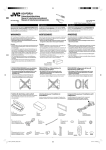
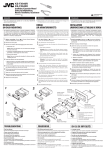
Required space for installation / Erforderlicher Platz für Einbau / Espacio requerido para la instalación
Caution when installing / Vorsicht bei der Installation /
Precaución en la instalación
• You cannot install the unit on the car which has any obstacles in the space indicated below.
• Sie können nicht die Einheit in einem Fahrzeug einbauen, wo sich Hindernisse in dem Bereich wie unten gezeigt befinden.
• La unidad no se puede instalar en un vehículo que presente algún obstáculo en el espacio indicado debajo.
Dashboard
Armaturenbrett
9.5 mm
2 mm
Tablero de instrumentos
Control panel
Schalttafel
Panel de control
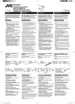
Trim plate is detached on this illustration for
explanation.
Die Deckplatte ist in dieser Zeichnung zur
Erklärung angebracht.
Para fines explicativos, se ha retirado la placa
de guarnición en esta ilustración.
Fit the unit into the mounting sleeve by using four corners of the trim
plate.
• DO NOT press the panel (shaded in the illustration).
Setzen Sie den Receiver in die Montagemanschette, indem Sie die vier
Ecken der Deckplatte verwenden.
• Drücken Sie NICHT auf die Platte selber (in der Abbildung schraffiert).
Introduzca el receptor en la manga de montaje utilizando las cuatro
esquinas de la placa decorativa.
• NO presione el panel (sombreado en la ilustración).
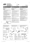
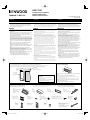
Parts list for installation and connection
Teileliste für den Einbau und Anschluß
Lista de piezas para instalación y conexión
The following parts are provided for this unit.
After checking them, please set them correctly.
Die folgenden Teile werden zusammen mit diesem Gerät geliefert. Nach
ihrer Überprüfung, die Teile richtig einsetzen.
Con esta unidad se suministran las siguientes piezas.
Después de inspeccionarlas, colóquelas correctamente.
A/B
C
D
E
Hard case/Control panel
Sleeve
Trim plate
Power cord
Etui/Schalttafel
Halterung
Frontrahmen
Stromkable
Estuche duro/Panel de
control
Cubierta
Placa de guarnición
Cordón de alimentación
F
G
H
I
J
Crimp connectors
Washer (ø5)
Lock nut (M5)
Mounting bolt—M5 x 20 mm
Rubber cushion
Crimpanschlüsse
Unterlegscheibe (ø5)
Sicherungsmutter (M5)
Befestigungsschraube—M5 x 20 mm
Gummipuffer
Conectores de sujeción
Arandela (ø5)
Tuerca de seguridad
(M5)
Perno de montaje—M5 x 20 mm
Cojín de goma
K
L
M
N
Handles
Remote controller
Reverse gear signal extension cord
Griffe
Fernbedienung
Manijas
Control remoto
Battery
Batterie
Pila
RückwärtsgangsignalVerlängerungskabel
Cable prolongador para señal del
engranaje de marcha atrás
1
KDV-7241_E_install_EGS.indb 1
08.4.18 2:53:37 PM
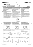
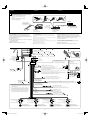
INSTALLATION
(IN-DASH MOUNTING)
EINBAU
(IM ARMATURENBRETT)
INSTALACIÓN (MONTAJE EN EL TABLERO DE
INSTRUMENTOS)
The following illustration shows a typical installation. If you have any
questions or require information regarding installation kits, consult
your Kenwood Car Audio dealer or a company supplying kits.
• If you are not sure how to install this unit correctly, have it installed
by a qualified technician.
• Make sure not to block the fan on the rear panel to maintain proper
ventilation when installed.
Die folgende Abbildung zeigt einen typischen Einbau. Wenn Sie weitere
Fragen haben oder Informationen zu Einbausätzen benötigen, wenden Sie
sich an Ihren Kenwood-Autoradiohändler oder an eine Bezugsquelle für
Einbausätze.
• Sind Sie sich über den richtigen Einbau des Geräts nicht sicher, lassen Sie
es von einem qualifizierten Techniker einbauen.
• Sicherstellen, dass nicht das Gebläse an der Rückseite verdeckt wird, um
richtige Ventilation beim Einbau zu gewährleisten.
La siguiente ilustración muestra una instalación típica. Si tiene
preguntas o requiere información concerniente a los juegos de
instalación, póngase en contacto con su distribuidor de audio para auto
Kenwood o con la compañía suministradora de los juegos.
• Si usted no está seguro de cómo instalar correctamente la unidad,
hágala instalar por un técnico cualificado.
• Asegúrese de no bloquear las rendijas de ventilación del panel trasero,
para poder mantener una buena ventilación una vez instalado.
Do the required electrical connections.
Nehmen Sie die erforderlichen elektrischen
Anschlüsse vor.
Realice las conexiones eléctricas
requeridas.
Do not block the fan.
Nicht das Gebläse blockieren.
No tape las rejillas de
ventilación.
*1 When you stand the unit,
be careful not to damage
the fuse on the rear.
1
* Beim Aufstellen des Geräts
darauf achten, daß die
Sicherung auf der Rückseite
nicht beschädigt wird.
Bend the appropriate tabs to hold the
sleeve firmly in place.
* Al poner la unidad
vertical, tenga cuidado
de no dañar el fusible
provisto en la parte
posterior.
1
When using the optional stay / Beim Verwenden der AnkerOption / Cuando emplea un soporte opcional
Die geeigneten Zapfen biegen, um die
Manschette sicher festzuhalten.
Doble las lengüetas apropiadas para
retener firmemente la manga en su lugar.
When installing the unit without using the sleeve / Beim Einbau des Geräts ohne Halterung / Instalación
de la unidad sin utilizar la cubierta
In a Toyota car for example, first remove the car radio and install the unit in its place.
Stay (option)
Zum Beispiel in einem Toyota zuerst das Autoradio ausbauen und dann das Gerät an seinem Platz einbauen.
Anker (Option)
En un automóvil Toyota, por ejemplo, en primer lugar desmonte el autorradio e instale la unidad en su lugar.
Soporte (opción)
Fire wall
Feuerwand
Tabique a prueba
de incendios
Flat type screws—M5 x 8 mm *2
Senkkopfschrauben—M5 x 8 mm *2
Tornillos tipo plano (M5 × 8 mm) *2
*2 Not included for this unit.
*2 Für diesen Receiver nicht mitgeliefert.
*2 No suministrado con esta unidad.
Dashboard
Armaturenbrett
Tablero de
instrumentos
Bracket *2
Konsole *2
Ménsula *2
Screw (option)
Schraube (Option)
Tornillo (opción)
Pocket
Taschen
Compartimiento
Bracket *2
Konsole *2
Ménsula *2
Install the unit at an angle of less than 30˚.
Stellen Sie das Gerät mit einem Winkel von
weniger als 30° auf.
Instale la unidad a un ángulo de menos de
30˚.
Flat type screws—M5 x 8 mm *2
Senkkopfschrauben—M5 x 8 mm *2
Tornillos tipo plano—M5 x 8 mm *2
Note:
When installing the unit on the mounting bracket, make sure to use the 8 mm-long screws. If longer screws are
used, they could damage the unit.
Hinweis:
Beim Anbringen des Gerät an der Konsole sicherstellen, daß 8 mm lange Schrauben verwendet werden. Werden längere
Schrauben verwendet, können sie das Gerät beschädigen.
Nota:
Cuando instala la unidad en la ménsula de montaje, asegúrese de utilizar los tornillos de 8 mm de longitud. Si se
utilizan tornillos más largos, éstos pueden dañar la unidad.
Removing the unit
Ausbau des Geräts
Extracción de la unidad
Before removing the unit, release the rear section.
Vor dem Ausbau des Geräts den hinteren Teil freigeben.
Antes de extraer la unidad, libere la sección trasera.
Insert the two handles, then pull them as
illustrated so that the unit can be removed.
Die beiden Handgriffe einsetzen und dann ziehen
wie in der Abbildung gezeigt, so daß das Gerät
entfernt werden kann.
Inserte las dos manijas y, a continuación,
extráigalas de la manera indicada en la ilustración
para poder desmontar la unidad.
2
KDV-7241_E_install_EGS.indb 2
08.4.18 2:53:40 PM
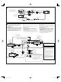
ELECTRICAL CONNECTIONS
ELEKTRISCHE ANSCHLÜSSE
CONEXIONES ELECTRICAS
To prevent short circuits, we recommend that you disconnect the
battery’s negative terminal and make all electrical connections before
installing the unit.
• Be sure to ground this unit to the car’s chassis again after
installation.
Notes:
• Replace the fuse with one of the specified rating. If the fuse blows
frequently, consult your Kenwood Car Audio dealer.
• It is recommended to connect to the speakers with maximum
power of more than 50 W (both at the rear and at the front, with an
impedance of 4 Ω to 8 Ω). If the maximum power is less than 50 W,
change “Amplifier Gain” setting to prevent the speakers from being
damaged (see page 35 of the INSTRUCTION MANUAL).
• To prevent short-circuit, cover the terminals of the UNUSED leads
with insulating tape.
• The heat sink becomes very hot after use. Be careful not to touch it
when removing this unit.
Zur Vermeidung von Kurzschlüssen empfehlen wir, daß Sie den negativen
Batterieanschluß abtrennen und alle elektrischen Anschlüsse herstellen,
bevor das Gerät eingebaut wird.
Para evitar cortocircuitos, recomendamos que desconecte el terminal
negativo de la batería y que efectúe todas las conexiones eléctricas antes
de instalar la unidad.
• Sicherstellen erneut, daß das Gerät nach dem Einbau Chassis • Asegúrese de volver a conectar a masa esta unidad al chasis
del automóvil después de la instalación.
des Fahrzeugs geerdet wird.
Notas:
Hinweise:
• Reemplace el fusible por uno con la corriente especificada. Si se
• Die Sicherung mit einer der entsprechenden Nennleistung ersetzen.
funden los fusibles frecuentemente, póngase en contacto con su
Wenn die Sicherung häufig durchbrennt, wenden Sie sich an Ihren
distribuidor de audio para auto Kenwood.
Kenwood-Autoradiohändler.
• Se recomienda conectar los altavoces con una potencia máxima de
• Es wird empfohlen, Lautsprecher mit einer Maximalleistung von
más de 50 W (tanto atrás como adelante, con una impedancia de
mehr als 50 W anzuschließen (sowohl hinten als auch vorne, mit
4 Ω a 8 Ω). Si la potencia máxima es de menos de 50 W, cambie
einer Impedanz von 4 Ω bis 8 Ω). Wenn die Maximalleistung
“Amplifier Gain” para evitar daños en los altavoces (consulte la
weniger als 50 W beträgt, stellen Sie „Amplifier Gain“ anders ein, um
página 35 del MANUAL DE INSTRUCCIONES).
Schäden an den Lautsprechern zu vermeiden (siehe Seite 35 der
• Para evitar cortocircuitos, cubra los cables NO UTILIZADOS con
BEDIENUNGSANLEITUNG).
cinta aislante.
• Zur Vermeidung eines Kurzschlusses die Anschlußklemmen der NICHT
• El sumidero térmico estará muy caliente después del uso. Asegúrese
VERWENDETEN Leitungen mit Isolierklebeband umwickeln.
de no tocarlo al desmontar esta unidad.
• Das Abstrahlblech wird nach dem Gebrauch sehr heiß. Beim Ausbau des
Geräts darauf achten, das Abstrahlblech nicht zu berühren.
Heat sink
Abstrahlblech
Sumidero térmico
PRECAUTIONS on power supply and speaker
connections:
VORSICHTSMASSREGELN beim Anschließen der
Stromversorgung und Lautsprecher:
PRECAUCIONES sobre las conexiones de la fuente de
alimentación y de los altavoces:
• DO NOT connect the speaker leads of the power cord to the
car battery; otherwise, the unit will be seriously damaged.
• BEFORE connecting the speaker leads of the power cord to the
speakers, check the speaker wiring in your car.
• Die Lautsprecherleitungen des Netzkabels NICHT an der
Autobatterie anschließen, da sonst das Gerät schwer
beschädigt wird.
• VOR dem Anschließen der Lautsprecherleitungen des
• NO conecte los conductores de altavoz del cable de
alimentación a la batería de automóvil, pues podrían
producirse graves daños en la unidad.
• ANTES de conectar a los altavoces los conductores de altavoz del
cable de alimentación, verifique el conexionado de altavoz de su
automóvil.
Spannunsgversorgungskabels an die Lautsprecher, die
Lautsprecherverdrahtung in Ihrem Auto überprüfen.
If your car is equipped with the ISO connector / Wenn Ihr
Fahrzeug mit dem ISO-Steckverbinder ausgestattet ist / SSi su
automóvil está equipado con el conector ISO
• Connect the ISO connectors as illustrated.
• Schließen Sie die ISO-Steckverbinder an, wie in der Abbildung gezeigt.
• Conecte los conectores ISO tal como se indica en la ilustración.
For some VW/Audi or Opel (Vauxhall) automobile / Bei bestimmten VW-/Audi- order Opel- (Vauxhall-)
Fahrzeugen / Para algunos automóviles VW/Audi u Opel (Vauxhall)
You may need to modify the wiring of the
supplied power cord as illustrated.
• Contact your authorized car dealer
before installing this unit.
Es kann erforderlich sein, die Verdrahtung des
mitgelieferten Stromkabels zu modifizieren,
wie in der Abbildung gezeigt.
• Wenden Sie sich vor dem Einbau dieses
Receivers an Ihre Auto-Fachwerkstatt.
Podría ser necesario modificar el
conexionado del cable de alimentación
suministrado, tal como se indica en la
ilustración.
• Antes de instalar esta unidad, consulte
a su concesionario de automóviles
autorizado.
Original wiring
Originalverdrahtung
From the car body
Conexionado original
Von der Fahrzeugkarosserie
ISO connector of the supplied power cord
ISO-Stecker des mitgelieferten Stromkabels
Conector ISO del cable de alimentación suministrado
Modified wiring 1 /
Modifizierte Verdrahtung 1 /
Conexionado modificado 1
*
Desde la carrocería del vehículo
*
ISO connector
Use modified wiring 2 if the unit does not turn on.
ISO-Steckverbinder
Verwenden Sie die modifizierte Verdrahtung 2 wenn der Receiver nicht einschaltet.
Si la unidad no se enciende, utilice el conexionado modificado 2.
Conector ISO
View from the lead side
Von der Kabelseite aus gesehen
* Choking coil
Vista desde el lado del conductor
Y: Yellow
R: Red
Drosselspule
Gelb
Rot
Bobina de reactancia
Amarillo
Rojo
Modified wiring 2
Modifizierte Verdrahtung 2
Conexionado modificado 2
*
A
Connecting the parking brake lead / Anschluss des Handbremsenkabels / Conexión del cable del freno de estacionamiento
Connect the parking brake lead to the parking brake system built
in the car.
Anschluss des Handbremsenkabels an das im Fahrzeug eingebaute
Handbremsensystem.
Conecte el cable del freno de estacionamiento al sistema de freno de
estacionamiento del automóvil.
Parking brake lead (light green)
Handbremsenkabel (hellgrün)
Cable del freno de estacionamiento (verde claro)
Parking brake
Handbremse
Freno de estacionamiento
To metallic body or chassis of the car
Zur metallenen Karosserie oder zum Fahrwerk des Autos
A un cuerpo metálico o chasis del automóvil
Parking brake switch (inside the car)
Handbremsenschalter (Fahrzeuginneres)
Interruptor del freno de estacionamiento
(dentro del automóvil)
3
KDV-7241_E_install_EGS.indb 3
08.4.18 2:53:41 PM
ENGLISH
B
DEUTSCH
ESPAÑOL
Connecting the REVERSE GEAR SIGNAL lead (for rear view camera) / Anschließen des REVERSE GEAR SIGNAL-Kabels (für die Rückfahrkamera) / Conexión del conductor
REVERSE GEAR SIGNAL (para la cámara trasera)
Locate the reverse lamp lead in the trunk.
Suchen Sie die Rückfahrleuchtenleitung im
Kofferraum.
Localice el conductor de la luz de marcha
atrás en el portaequipajes.
KDV-7241
Reverse lamp lead
Rückfahrleuchtenleitung
Conductor de la luz
de marcha atrás
REVERSE GEAR SIGNAL
To reverse lamp
Purple with white stripe
An Rückfahrleuchte
A la luz de marcha
atrás
Reverse lamps
Lila mit weißem Streifen
Púrpura con rayas blancas
Reverse lamp lead
Rückfahrleuchtenleitung
Rückfahrleuchte
Conductor de la luz de
marcha atrás
Luces de marcha atrás
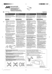
Connections without using the ISO connectors
Anschlüsse ohne Verwendung der ISO-Steckverbinder
Conexiones sin usar los conectores ISO
Before connecting: Check the wiring in the vehicle carefully.
Incorrect connection may cause serious damage to this unit.
The leads of the power cord and those of the connector from the car
body may be different in color.
Vor dem Anschließen: Die Verdrahtung im Fahrzeug sorgfältig
überprüfen. Falsche Anschlüsse können ernsthafte Schäden am Gerät
hervorrufen.
Die Leiter des Stromkabels und die Leiter des Anschlusses im Fahrzeug
können sich farblich unterscheiden.
Antes de la conexión: Verifique atentamente el conexionado del
vehículo. Una conexión incorrecta podría producir daños graves en la
unidad.
Los cordones del cable de alimentación y los del conector procedentes de
la carrocería del automóvil podrían ser de diferentes en color.
1 Cut the ISO connector.
2 Connect the colored leads of the power cord in the order specified
in the illustration below.
3 Connect the aerial cord.
4 Finally connect the wiring harness to the unit.
1 Corte el connector ISO.
1 Schneiden Sie den ISO-Steckverbinder auf.
2 Conecte los conductores de color del cable de alimentación en el
2 Die farbigen Adern des Stromkabels in der Reihenfolge anschließen, wie
orden especificado en la ilustración de abajo.
in der Abbildung unten gezeigt.
3 Conecte el cable de antena.
3 Das Antennenkabel anschließen.
4 Por último, conecte el cable de alimentación a la unidad.
4 Die Kabelbäume am Gerät anschließen.
LINE IN (see diagram
/ siehe Schaltplan
LINE OUT (FRONT/REAR)
(see diagram / siehe Schaltplan
/ véase diagrama )
/ siehe Schaltplan
VIDEO IN (see diagram
/ siehe Schaltplan
VIDEO OUT (see diagram
Rear ground
terminal
/ véase diagrama )
/ véase diagrama )
/ véase diagrama )
Do not connect. / Nicht anschließen. / Ne pas connecter.
Hintere Erdungscanschlußklemme
15 A fuse
15 A Sicherung
Terminal de tierra
posterior
Fusible de 15 A
*3 Not included for this unit
*3 Für diesen Receiver nicht mitgeliefert
*3 No suministrado con esta unidad.
Ignition switch
Zündschalter
Interruptor de encendido
Black
Schwarz
Negro
To metallic body or chassis of the car
Zur metallenen Karosserie oder zum Fahrwerk des Autos
SUBWOOFER
(see diagram / siehe Schaltplan
véase diagrama )
Yellow *4
Gelb *4
Amarillo *4
/
A un cuerpo metálico o chasis del automóvil
To a live terminal in the fuse block connecting to the car battery (bypassing the
ignition switch) (constant 12 V)
Zur einer stromführenden Anschlußklemme im Sicherungsblock zum Anschließen an
die Autobatterie (Umgehen des Zündschalters) (konstant 12 V)
A un terminal activo del bloque de fusibles conectado a la batería del automóvil
(desviando el interruptor de encendido) (12 V constantes)
Fuse block
Red
Sicherungsblock
Rot
Rojo
Bloque de fusibles
To an accessory terminal in the fuse block
Zur einer Zubehöranschlußklemme im Sicherungsblock
A un terminal accesorio del bloque de fusibles
Blue with white stripe
Blau mit weißem Streifen
REVERSE GEAR SIGNAL
(see diagram / siehe Schaltplan
véase diagrama )
Azul con rayas blancas
To the power control lead of other equipment or power aerial if any (200 mA max.)
/
* Before checking the operation of this unit prior to
installation, this lead must be connected, otherwise power
cannot be turned on.
*4 Vor der Überprüfung der Funktionsfähigkeit des Geräts vor
4
dem Einbau, muß diese Leitung angeschlossen werden, da
sonst die Stromversorgung nicht eingeschaltet werden kann.
*4 Antes de comprobar el funcionamiento de esta unidad
previa a de la instalación, es necesario conectar este cable,
de lo contrario no se podrá conectar la alimentación.
Zum Leistungsreglerkabel des anderen Geräts oder zur Antenne, sofern vorhanden (max. 200 mA)
Al control de energía del otro equipo o a la antena de energía si es que existe (máx. 200 mA)
Orange with white stripe
Orange mit weißem Streifen
Naranja con rayas blancas
To car light control switch
Zum Autobeleuchtungssteuerung-Schalter
Al interruptor de control de las luces del automóvil
Brown
Braun
Marrón
To cellular phone system
An Mobiltelefonsystem
Light green
Al sistema de teléfono celular
Hellgrün
To parking brake (see diagram
Verde claro
)
An Feststellbremse (siehe Schaltplan
)
Al freno de estacionamiento (véase diagrama
White with black stripe
Weiß mit schwarzem
Streifen
Blanco con rayas negras
White
Weiß
Blanco
Gray with black stripe
Gray
Green with black stripe
Grau mit schwarzem
Streifen
Grau
Grün mit schwarzem
Streifen
Gris con rayas negras
Gris
Verde con rayas negras
Green
Grün
Verde
Purple with black stripe
Lila mit schwarzem
Streifen
)
Purple
Lila
Púrpura
Púrpura con rayas negras
Left speaker (front)
Right speaker (front)
Left speaker (rear)
Right speaker (rear)
Linker Lautsprecher (vorne)
Rechter Lautsprecher (vorne)
Linker Lautsprecher (hinten)
Rechter Lautsprecher (hinten)
Altavoz izquierdo (delantero)
Altavoz derecho (delantero)
Altavoz izquierdo (trasero)
Altavoz derecho (trasero)
4
KDV-7241_E_install_EGS.indb 4
08.4.18 2:53:41 PM
A
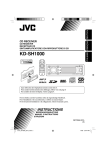
Connections for external component playback / Anschlüsse für externe Komponente / Conexiones para la reproducción del componente externo
VIDEO IN
Camcorder, rear view camera, etc.
KDV-7241
Camcorder, Rückfahrkamera, usw.
Videocámara, cámara de retrovisión, etc.
LINE IN
External component
Externe Komponente
Componente externo
VIDEO OUT
External monitor
Externer Monitor
Monitor externo
Video cord (not supplied)
Videokabel (nicht mitgeliefert)
Cordón de video (no suministrado)
B
Connecting the external amplifiers / Anschließen der externen Verstärker / Conexión al control remoto del volante de dirección
You can connect amplifiers to upgrade your car stereo system.
• Connect the power control lead (blue with white stripe) to the
power control lead of the other equipment so that it can be
controlled through this unit.
• For amplifier only:
– Disconnect the speakers from this unit, connect them to
the amplifier. Leave the speaker leads of this unit unused.
– You can switch off the built-in amplifier and send the audio
signals only to the external amplifier(s) to get clear sounds and
to prevent internal heat built-up inside the unit. See page 35 of
the INSTRUCTION MANUAL (separate volume).
Sie können einen Verstärker anschließen, um Ihre Autostereoanlage zu
erweitern.
• Schließen Sie das Leistungsreglerkabel (blau mit weißem Streifen) an das
Leistungsreglerkabel des anderen Gerätes an, so dass dieses von Ihrem
Gerät aus gesteuert werden kann.
• Nur für den Verstärker:
– Die Lautsprecher von diesem Gerät abtrennen und am
Verstärker anschließen. Die Lautsprecherleitungen dieses
Geräts unbenutzt lassen.
– Sie können den eingebauten Verstärker abschalten und die
Audiosignale nur zu dem(n) externen Verstärker(n) ausgeben, um
scharfen Ton zu erhalten und Hitzestau im Receiver zu vermeiden.
Siehe Seite 35 der BEDIENUNGSANLEITUNG (separate Druckschrift).
Usted podrá conectar un amplificadores para mejorar el sistema
estéreo de su automóvil.
• Conecte el cable de control de energía (azul con una línea blanca)
en el cable de control de energía del otro equipo de tal modo que se
pueda controlar a través de esta unidad.
• Sólo para el amplificador:
– Desconecte los altavoces de esta unidad y conéctelos al
amplificador. Los cables de los altavoces de esta unidad
quedan sin usar.
– Podrá desconectar el amplificador incorporado y enviar las
señales de audio solamente al(los) amplificador(es) externo(s)
para obtener sonidos nítidos y evitar que se caliente el interior
de la unidad. Consulte la página 35 del MANUAL DE
INSTRUCCIONES (volumen separado).
Power control lead
Leistungsreglerkabel
Power control lead
Cable de control de energía
Leistungsreglerkabel
Cable de control de energía
Power control lead (Blue with white stripe)
Leistungsreglerkabel (Blau mit weißem Streifen)
Cable de control de energía (Azul con rayas blancas)
{
Rear speakers
Hintere Lautsprecher
SUBWOOFER
Altavoces traseros
Amplifier
Verstärker
Amplificador
KDV-7241
Amplifier
Verstärker
Subwoofer
Amplificador
Subwoofer
Subwoofer
LINE OUT (REAR)
Rear speakers
Front speakers
Hintere Lautsprecher
Vordere Lautsprecher
Altavoces delanteros
*5 Audio cord (not supplied)
*5 Audiokabel (nicht mitgeliefert)
*5 Cable de audio (no suministrado)
Altavoces traseros
LINE OUT (FRONT)
Front speakers
Vordere Lautsprecher
Altavoces delanteros
Amplifier
Verstärker
*7 Cut the rear speaker leads of the car’s ISO
connector and connect them to the amplifier.
Amplificador
*
7
Schneiden Sie die hinteren Lautsprecherkabel
des ISO-Steckverbinders des Fahrzeugs ab, und
schließen diese an den Verstärker an.
*7 Corte los conductores de los altavoces
posteriores del conector ISO del autómovil y
conéctelos al amplificador.
*6 Firmly attach the ground lead to the metallic
body or to the chassis of the car—to the
place uncoated with paint (if coated with
paint, remove the paint before attaching the
lead). Failure to do so may cause damage to
the unit.
6
* Verbinden Sie den Erdungsleiter mit der
Karosserie oder dem Rahmen des Fahrzeugs.
Die Kontaktstelle darf nicht lackiert sein (sollte
die Kontaktstelle lackiert sein, entfernen Sie
den Lack der Kontaktstelle, bevor Sie den Leiter
befestigen). Wenn der Erdungsleiter nicht
ordnungsgemäß angeschlossen wird, kann
dieses Gerät beschädigt werden.
*6 Fije firmemente el cable de tierra a la
carrocería metálica o al chasis—a un lugar
no cubierto con pintura (si está cubierto con
pintura, quítela antes de fijar el cable). De lo
contrario, se podrían producir daños en la
unidad.
5
KDV-7241_E_install_EGS.indb 5
08.4.18 2:53:42 PM
TROUBLESHOOTING
•
*
•
*
•
*
•
*
*
•
*
•
*
*
•
*
The fuse blows.
Are the red and black leads connected correctly?
Power cannot be turned on.
Is the yellow lead connected?
No sound from the speakers.
Is the speaker output lead short-circuited?
Sound is distorted.
Is the speaker output lead grounded?
Are the “–” terminals of L and R speakers grounded in common?
Noise interfere with sounds.
Is the rear ground terminal connected to the car’s chassis using
shorter and thicker cords?
Unit becomes hot.
Is the speaker output lead grounded?
Are the “–” terminals of L and R speakers grounded in common?
This unit does not work at all.
Have you reset your unit?
FEHLERSUCHE
LOCALIZACIÓN DE AVERIAS
• Die Sicherung brennt durch.
* Sind die roten und schwarzen Leitungen richtig angeschlossen?
• Stromversorgung kann nicht eingeschaltet werden.
* Ist die gelbe Leitung angeschlossen?
• Kein Ton aus den Lautsprechern.
* Ist die Lautsprecherausgangsleitung kurzgeschlossen?
• Ton verzerrt.
* Ist die Lautsprecherausgangsleitung geerdet?
* Sind die (–) Anschlußklemmen der linken und rechten Lautsprecher
zusammen geerdet?
•
*
•
*
•
*
•
*
*
• Störgeräusche im Klang.
* Ist die hintere Erdungsklemme mit kürzeren und dickeren Kabeln an das
Fahrzeugchassis angeschlossen?
•
*
• Gerät wird heiß.
* Ist die Lautsprecherausgangsleitung geerdet?
* Sind die (–) Anschlußklemmen der linken und rechten Lautsprecher
zusammen geerdet?
•
*
*
• Diese Einheit funktioniert überhaupt nicht.
* Haben Sie Ihre Einheit zurückgesetzt?
•
*
El fusible se quema.
¿Están los conductores rojo y negro correctamente conectados?
No es posible conectar la alimentación.
¿Está el cable amarillo conectado?
No sale sonido de los altavoces.
¿Está el cable de salida del altavoz cortocircuitado?
El sonido presenta distorsión.
¿Está el cable de salida del altavoz conectado a masa?
¿Están los terminales “–” de los altavoces L y R conectados a una
masa común?
Perturbación de ruido.
¿El terminal de tierra trasero está conectado al chasis del automóvil
utilizando los cordones más corto y más grueso?
La unidad se calienta.
¿Está el cable de salida del altavoz conectado a masa?
¿Están los terminales “–” de los altavoces L y R conectados a una
masa común?
Este receptor no funciona en absoluto.
¿Reinicializó el receptor?
6
KDV-7241_E_install_EGS.indb 6
08.4.18 2:53:43 PM


![KD-AVX11[E] Installation (EN, GE, FR, NL)](http://vs1.manualzilla.com/store/data/006336435_1-79ed9978e32311edad214be22becc7b9-150x150.png)