Download MODO INFINITY.indd

Transcript
DICHIARAZIONE DI CONFORMITA'
Il fabbricante:
FARO S.p.A.
Via Faro, 15
20060 Ornago (Milano) ITALY
E' conforme alle seguenti norme tecniche:
Dichiara sotto la propria responsabilità, che il prodotto:
Designazione del prodotto: Micromotore da studio
Modello:
E' conforme alle seguenti Direttive europee ed ai rispettivi recepimenti nazionali e modifiche successive.
93/42/CEE (direttiva dispositivi medici)
Classe di appartenenza dell'apparecchio: IIa
Modo Infinity
E' nuovo di fabbrica, secondo quanto previsto dall'art. 6 par. 2
del D.L. 626/94.
CEI EN 60601-1: 1990
CEI EN 60601-1-2: 2006
CEI EN 61000-3-2: 2006
CEI EN 61000-3-3/A2: 2005
CEI EN 60825-1: 2007
EN 14971: 2000
EN 980: 2003
EN 1041: 1998
Dott. Angelo Favonio
Amministratore Delegato
La presente è una riproduzione conforme all'originale, che è archiviato presso il fabbricante con i relativi numeri di serie
1
DECLARATION OF CE CONFORMITY
The manufacturer:
FARO S.p.A.
Via Faro, 15
20060 Ornago (Milano) ITALY
declares under its own responsability that following product:
Product name:
Office Micromotor
Model in the version:
Modo Infinity
It is factory new in accordance with the provisions of art. 6
para 2 of D.L. 626/94.
It fully fills to the following European directives and
national acceptances:
93/42/CEE (medical devices directive)
Class [which the equipment belongs to]: II a
It conforms to the following standards:
CEI EN 60601-1: 1990
CEI EN 60601-1-2: 2006
CEI EN 61000-3-2: 2006
CEI EN 61000-3-3/A2: 2005
CEI EN 60825-1: 2007
EN 14971: 2000
EN 980: 2003
EN 1041: 1998
Dott. Angelo Favonio
Managing Director
2
INDICE GENERALE
•
•
•
•
•
•
•
•
•
Simbologie utilizzate nel manuale
Norme di sicurezza
Caratteristiche
Descrizione delle parti
Installazione
Istruzioni d'uso
Manutenzione
Guida ai problemi più comuni
Specifiche tecniche
pag.
pag.
pag.
pag.
pag.
pag.
pag.
pag.
pag.
3
4
5-6-7-8
9
10
11-12
13
14-15
16
17-18
SIMBOLOGIE UTILIZZATE NEL MANUALE
Pericolo
I paragrafi contrassegnati con questo simbolo,
contengono istruzioni che devono essere eseguite
attentamente per evitare danni al dispositivo,
all'operatore ed eventualmente al paziente.
Avvertenze
Queste istruzioni avvisano che bisogna porre
molta attenzione per evitare situazioni che potrebbero danneggiare il dispositivo.
Leggere attentamente le istruzioni prima dell’uso.
4
Divieto
Questa icona mette in evidenza cosa non si
deve fare per evitare danni al dispositivo.
Suggerimenti
Con questa icona, viene fornita un'informazione che permette di usare il dispositivo
in modo più efficace.
Smaltire il dispositivo attenendosi alle
norme per la raccolta differenziata
del materiale elettrico.
NORME DI SICUREZZA
• Seguire tutte le indicazioni riportate nel presente manuale.
• Il motore deve essere alimentato dalla scheda dedicata FARO PN 617300; l’installazione non corretta del dispositivo può pregiudicare la rispondenza alle norme di sicurezza; per l'installazione
vedi manuale scheda.
• Il dispositivo deve essere utilizzato in uno studio dentistico solo da personale medico.
• Al fine di evitare la contaminazione incrociata fra pazienti, inserire o disinserire il
micromotore dal manipolo avendo cura di evitare il contatto con mani o guanti contaminati.
• Dispositivo non protetto contro la penetrazione dei liquidi.
• Il dispositivo non è fornito sterile, quindi deve essere pulito prima dell'utilizzo (vedi pag.10).
• Il dispositivo non è sterilizzabile.
• Non puntare direttamente la luce led negli occhi, in quanto dispositivo classe II secondo
norma EN 60825-1.
5
• Il micromotore da studio "Modo Infinity" non richiede lubrificazione.
• Al dispositivo viene connesso un apparecchio "manipolo dentale", conforme alla norma
UNI EN 23964.
• Verificare nell'installazione finale la rigidità dielettrica e le correnti di dispersione in
accordo alla EN 60601-1.
• Non effettuare alcun tentativo di manutenzione sulla parte elettrica. Non tentare di intervenire
personalmente sul micromotore da studio o sul circuito elettronico corrispondente.
• Eseguire solo le operazioni illustrate nel presente manuale; in qualsiasi altro caso rivolgersi
all'assistenza tecnica.
• L'apparecchio nell' imballo originale può essere trasportato o tenuto in magazzino per un periodo
di 15 settimame se vengono rispettate le seguenti condizioni ambientali:
⇒ Temperatura ambiente da -20°C a +70°C
⇒ Umidità relativa dal 10% al 90%
⇒ Pressione atmosferica da 500 a 1060 mBar.
• Apparecchio non protetto sugli effetti della scarica di un defibribillatore.
6
REQUISITI PER LA COMPATIBILITA’ ELETTROMAGNETICA
Il dispositivo medico necessita di particolari precauzioni per quanto concerne la compatibilità elettromagnetica e deve essere installato e
utilizzato secondo le informazioni fornite con i documenti di accompagnamento.
Guida e dichiarazione del costruttore – Emissioni Elettromagnetiche
Il micromotore “Modo Infinity” è utilizzabile nell’ambiente elettromagnetico di seguito specificato. Il cliente o l’utente del micromotore devono
assicurarsi che l’apparecchio sia utilizzato in tale ambiente
Test di Emissioni
Compliance
Guida all’ambiente elettromagnetico
Il micromotore “modo infinity” utilizza energia
RF solo per la sua funzione interna. Pertanto le
Emissioni Irradiate
Class B , Group1
sue emissioni RF sono molto basse e non
CISPR11
causano alcuna interferenza in prossimità di
alcun apparecchio elettronico.
Emissioni Condotte
Il micromotore “modo infinity” è adatto per
Class B , Group1
CISPR11
essere usato in studi dentistici ed ambienti
connessi direttamente alla rete di distribuzione
Armoniche
Class A
pubblica che fornisce alimentazione a tali
IEC/EN 61000-3-2
ambienti..
Fluttuazioni di tensione / flicker
Conforme
IEC/EN 61000-3-3
7
Guida e dichiarazione del costruttore – Immunità Elettromagnetiche
Il micromotore “modo infinity” è utilizzabile nell’ambiente elettromagnetico di seguito specificato. Il cliente o l’utente del micromotore devono
assicurarsi che l’apparecchio sia utilizzato in tale ambiente
Test di Emissione
Compliance
Guida all’ambiente elettromagnetico
Scariche elettrostatiche (ESD)
I pavimenti dovrebbero essere in legno, cemento
±6kV a contatto
IEC/EN61000-4-2
o ceramica. Se i pavimenti sono coperti di
±8kV in aria
materiale sintetico, l’umidità relativa dovrebbe
essere al massimo il 30%
Transitori veloci/burst
L’alimentazione dovrebbe essere quella tipica di
±2kV
IEC/EN61000-4-4
un ambiente commerciale o ospedale
Surge
IEC/EN61000-4-5
Buchi di tensione, brevi interruzioni e variazioni
di tensione
IEC/EN61000-4-11
Campo magnetico
IEC/EN61000-4-8
Immunità Condotte
IEC/EN61000-4-6
Immunità Irradiate
IEC/EN61000-4-3
±1kV modo differenziale
±2kV modo comune
<5%UT per 0.5 cycle del ciclo
40%UT prt 05 cycle del ciclo
70%UT per 25 cycle del ciclo
<5%UT
per 5 sec
3Vrms 150kHz to 80MHz
L’alimentazione dovrebbe essere quella tipica di
un ambiente commerciale o ospedale
L’alimentazione dovrebbe essere quella tipica di
un ambiente commerciale o ospedale. Se
l’utente del micromotore richiede che
l’apparecchio operi in continuazione, si
raccomanda di utilizzarlo sotto un gruppo di
continuità..
Il campo magnetico dovrebbe quello tipico di un
ambiente commerciale o ospedaliero
--
3V/m 80MHz to 2.5GHz
--
3A/m
Nota UT è il valore della tensione di alimentazione
8
CARATTERISTICHE
Versioni micromotori da studio "Modo Infinity":
Intramatic led 40IL - Intramatic led 40ILU
- I micromotori della serie "Modo Infinity" sono predisposti per fornire energia cinetica ad un manipolo
(non in dotazione) da connettere alla sua estremità. Il dispositivo permette, il passaggio di acqua e
aria per lo spray di raffreddamento della fresa; inoltre fornisce luce ai manipoli dotati di fibra ottica.
- Cordone dedicato permette di alimentare la versione "Modo Infinity"
modello 40IL (intramatic-led)
- Cordone unificato micromotore/turbina permette di alimentare la versione "Modo Infinity"
modello 40ILU (intramatic-led-unificato)
9
DESCRIZIONI DELLE PARTI
1
2
3
4
Innesto al manipolo
Guarnizione O-ring
Aria
Acqua
1
Ø21,8
Dimensioni
2
65
98
10
3
4
INSTALLAZIONE
Verificare che nelle confezione vi siano i seguenti componenti:
- Micromotore
- N°3 guarnizioni O-ring
- Manuale di istruzione
• IL DISPOSITIVO PUÒ ESSERE INSTALLATO SUL CORDONE DALL'UTILIZZATORE.
• Modello "40IL"
Inserire il micromotore nella basetta del cordone dedicato.
Avvitare la ghiera del cordone di alimentazione al micromotore, ruotandola in senso orario.
• Modello "40ILU"
Svitare la ghiera turbina dal cordone unificato FARO e inserire il micromotore nella basetta del
cordone avvitandolo alla ghiera.
11
INSTALLAZIONE
• Modello "40ILU"
Svitare la ghiera "A" turbina dal cordone unificato FARO e inserire il micromotore nella basetta del cordone.
A
12
ISTRUZIONI D'USO
Dopo aver collegato il micromotore al cordone accertarsi del
buon funzionamento controllando:
• Nelle versioni, 40IL-40ILU, che fuoriesca dai fori, in
corrispondenza delle guarnizioni O-ring, ARIA foro "A" e
ACQUA foro "B" (fig. 1) e che il led si accenda.
Dopo queste verifiche innestare il manipolo e controllare che
non ci siano perdite di acqua e aria sull'innesto del cordone.
IMPORTANTE
Non inserire il manipolo quando il micromotore è in
rotazione.
13
A
B
fig. 1
MANUTENZIONE
-
All'installazione il dispositivo da studio deve essere pulito.
Il dispositivo da studio deve essere pulito dopo ogni intervento e prima di ogni utlizzo.
Prima di pulire il dispositivo scollegarlo dal cordone di alimentazione.
Dispositivo non protetto contro la penetrazione di liquidi.
Pulire il micromotore, compreso il cordone, con un panno imbevuto di disinfettante o di un prodotto
detergente non abrasivo.
IL DISPOSITIVO NON È STERILIZZABILE.
UTILIZZARE SOLO RICAMBI FARO PER IL MANTENIMENTO DELLA QUALITA'
E LA RISPONDENZA ALLE NORME.
14
Lubrificazione
Nelle versioni "Modo 40Il e 40ILU" si consiglia di
lubrificare regolarmente con grasso di vaselina le tre
guarnizioni "A", al fine di limitarne l'usura e garantire
la perfetta tenuta dell'acqua e dell'aria (fig. 2). Nel caso
fossero usurate devono essere sostituite.
A
IMPORTANTE
Non lubrificare nessun altro particolare
meccanico del micromotore.
fig. 2
15
GUIDA AI PROBLEMI PIU' COMUNI
- Il micromotore
perde acqua o aria.
- Controllare le guarnizioni O-ring poste sull'innesto del manipolo. Nel caso
fossero usurate sostituirle (vedi pag.15 fig.2).
- Consultate l'assistenza FARO nel caso il problema persista.
- Il micromotore
non gira.
- Verificare che il cordone sia innestato correttamente.
- Consultare l'assistenza FARO, nel caso il problema persista.
- Il led non si accende.
- Consultare l'assistenza FARO.
- Perdite aria-acqua
innesto cordone
- Verificare l'accoppiamento motore/cordone.
- Consultare l'assistenza FARO nel caso il problema persista.
16
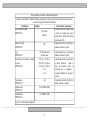
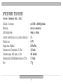
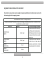
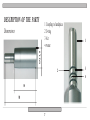
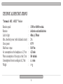
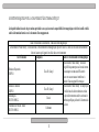
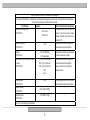
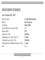
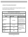
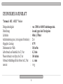
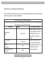
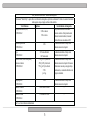
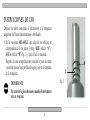
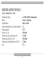
SPECIFICHE TECNICHE
Versione "Intramatic 40IL / 40ILU"
Velocità di rotazione
Rotazione
Led illuminazione
Corrente assorbita max (con circuito dedicato)
Potenza resa
Coppia max all'albero
Consumo aria al manipolo a 2,5 bar
Consumo acqua dello spray a 2 bar
Consumo aria di raffreddamento motore a 2,5 bar
Peso
:
:
:
:
:
:
:
:
:
:
da 1.500 a 40.000 giri/min.
oraria e antioraria
40lm @ 350mA
2A
45 W
10,8 mNm
4,2 l/min
160 ml/min
12 l/min
75 g
17
Servizio con carico intermittente S3 (CEI 34-1)
2
A 60 sec. ON - 10 min OFF
1,5 A 90 sec. ON - 12 min OFF
1
A 120 sec. ON - 6 min OFF
Dispositivo in classe II
Radiazioni led
Non fissare il fascio
Apparecchio Led di Classe 2
Parte applicata tipo BF
Etichettatura conforme alla norma EN 60825-1
18
CERTIFICATO DI GARANZIA
La FARO concede al cliente finale una garanzia di 12 mesi a partire dalla data di acquisto.
La riparazione in garanzia deve essere effettuata presso la FARO; spese e rischi di trasporto sono a rischio
dell’acquirente.
La riparazione in garanzia è ritenuta valida solo quando:
− il certificato è stato compilato in tutte le sue parti e inviato anticipatamente alla FARO tramite
Fax ( 039.6010540).
La garanzia risponde dei guasti dovuti alla cattiva qualità del materiale o a difetti di fabbricazione, in caso
di fondato reclamo la garanzia consente la riparazione o la sostituzione gratuita. E’ esclusa la possibilità di
ottenere risarcimento di danni e/o di interessi. La garanzia non è ritenuta valida, a insindacabile giudizio
della FARO, in caso di manomissione, danneggiamento, di scorretta utilizzazione, di cattiva manutenzione o
di normale usura.
19
CONTEXT
•
•
•
•
•
•
•
•
•
Symbols used in the manual
Safety norms
Features
Description of the parts
Installation
Instruction for use
Maintenance
Troubleshooting
Technical specifications
page
page
page
page
page
page
page
page
page
20
21
22-23-24-25
26
27
28-29
30
31-32
33
34-35
SYMBOLS USED IN THE MANUAL
Danger
Forbidden
Paragraphs marked with this symbol contain
instructions to be followed carefully to avoid damage to the device, the operator and patient.
This icon points out what to prevent doing
to not damage the device.
Warning
Information for most effective device
use.
These instructions advise that great care must
be taken to avoid situations that could damage
the system.
Read carefully the instructions before use.
21
Suggestions
Dispose of the system in accordance with
regulations for the separate collection of
electrical material.
SAFETY NORMS
• Follow all instructions shown in the following manual.
• The motor must be powered by a FARO PN 617300 dedicated card; The wrong installation can influence
the correspondence to the safety norms; for installation see card manual.
• Installation of the system must only be performed in a dental studio by specialized staff
staff.
• In order to avoid cross contamination between patients, insert or disconnect the dental studio
micro-motor from the handpiece, avoiding contact with contaminated hands and gloves.
• The device is not protected by possible liquid penetration.
• The device is not supplied as sterilized, therefore it must be cleaned before use (See page 28).
• The device cannot be sterilized.
• According to EN 60825-1, don’t point the led light directly into eyes, since the device belongs to
class II.
22
• The dental studio micro-motor “Modo Infinity” does not require lubrication.
• The device is connected to a “dental handpiece” conform to UNI EN 23964.
• During final installation check the dielectric rigidity and the leakage currents along with
EN 60601-1.
• Do not attempt to repair the electrical parts. Do not intervene directly either on the dental
studio micro-motor or on the corresponding electronic circuit.
• Carry out only the operations explained in this manual. In any other case contact the customer
service.
• The device in its original packaging can be transported or kept in storage for a period of 15 weeks
if the following environmental conditions are observed:
⇒ Ambient temperature from –20° C to + 70°C
⇒ Relative humidity from 10% to 90%
⇒ Atmospheric pressure from 500 to 1060 mBar.
• The device is not protected from the effects of defibrillator electric shocks.
23
REQUIREMENTS FOR ELECTROMAGNETIC COMPATIBILITY
This medical device requires particular precautions regarding electromagnetic compatibility and must be installed and used in accordance with
the information supplied with the accompanying documents.
Guide and manufacturer’s declaration – Electromagnetic Emissions
The dental studio micro-motor “Modo Infinity” can be used in the electromagnetic environment specified as follows. The customer or user must
ensure that the device is used in that environment
Emissions test
Compliance
Guide to the electromagnetic environment
The dental studio micro-motor “modo infinity”
uses RF energy only for its internal operation.
Irradiated Emissions
The RF emissions are therefore very low and do
Class B , Group1
CISPR11
not cause any interference when near any other
electronic device.
Conducted emissions
The dental studio micro-motor “modo infinity”
Class B , Group1
CISPR11
is suitable for use in dental studios and
environments connected directly to the public
Harmonic
Class A
mains supplying power to those environments.
IEC/EN 61000-3-2
Harmonic
Conform
IEC/EN 61000-3-3
24 – Electromagnetic Immunity
Guide and manufacturer’s declaration
IEC/EN 61000-3-3
Conform
Guide and manufacturer’s declaration – Electromagnetic Immunity
The dental studio micro-motor “Modo Infinity” can be used in the electromagnetic environment specified as follows. The customer or user must
ensure that the device is used in that environment
Emissions test
Compliance
Guide to the electromagnetic environment
Floors should be in wood, cement or ceramic
Electrostatic discharges (ESD)
�6kV by contact
tiles. If floors are covered in synthetic material,
IEC/EN61000-4-2
�8kV in the air
the relative humidity must be a maximum of
30%.
Fast transients/bursts
The power supply should be that of a
�2kV
IEC/EN61000-4-4
commercial or hospital environment.
Surge
IEC/EN61000-4-5
Voltage dips, brief interruptions and voltage
variations
IEC/EN61000-4-11
Magnet field
IEC/EN61000-4-8
Conducted immunity
IEC/EN61000-4-6
Irradiated immunity
IEC/EN61000-4-3
3Vrms 150kHz to 80MHz
The power supply should be that of a
commercial or hospital environment.
The power supply should be that of a
commercial or hospital environment. If the user
of the dental studio micro-motor needs the
device to be used continuously, an
uninterruptible power supply is recommended.
The magnetic field should be that of a
commercial or hospital environment.
--
3V/m 80MHz to 2.5GHz
--
�1kV differential modus
�2kV traditional modus
<5%UT per 0.5 cycle of cycle
40%UT per 05 cycle of cycle
70%UT per 25 cycle of cycle
<5%UT
per 25 cycle of cycle
3A/m
Note UT is the power supply voltage value
25
FEATURES
Dental studio micro-motor versions “Modo Infinity”:
Intramatic led 40IL – Intramatic led 40ILU
- The dental studio micro-motor series “Modo Infinity” supply kinetic energy to a handpiece (not supplied)
to be connected to its end. The device allows the passage of water and air through the cooling spray of
the cutter, and gives light to the handpieces provided with optic fiber.
- The dedicated cord allows to supply the “Modo Infinity” version, model 40IL (intramatic-led)
- The unified cord micro-motor/turbine allows to supply power to the “Modo Infinity”, model 40ILU
(unified-intramatic-led)
26
DESCRIPTION OF THE PARTS
1
2
3
4
Coupling to handpiece
O-ring
Air
Water
1
Ø21,8
Dimensions
2
65
98
27
3
4
INSTALLATION
Check that the package contains the following components:
- Micro-motor
- 3 O-rings
- Instruction manual
• THE DEVICE CAN BE INSTALLED ON THE USER’S CORD.
• ”40IL” model
Insert the micro-motor into the dedicated cord junction block.
Screw the ring nut of the feeding cord to the micro-motor, by rotating it clockwise.
• ”40ILU” model
Unscrew the turbine ring nut from the FARO unified cord and insert the micro-motor into the
junction block of the cord, by screwing it to the ring nut.
28
INSTALLATION
• "40ILU" model
Unscrew the ring nut turbine “A” from the FARO unified cord, and insert the micro-motor into the junction
block of the cord.
A
29
INSTRUCTIONS FOR USE
After having connected the micro-motor to the cord, ensure its
good functioning as follows:
• In the 40IL-40ILU versions it should come out of the holes in correspondence with the O-rings, AIR from hole “A”
and WATER from hole “B” (fig. 1). Led should go on.
After this, engage the handpiece and check that there are no
water or air leaks on the cord coupling.
IIMPORTANT
Do not insert the handpiece when the micro-motor
rotates.
30
A
B
fig. 1
MAINTENANCE
-
During installation the device must be cleaned.
The device must be cleaned after every surgical intervention and before every use.
Before cleaning the device, disconnect from the feeding cord.
The device is not protected by liquid penetration.
Clean the micro-motor, including the cord, with a cloth soaked in a disinfectant or in a non abrasive
detergent.
THE DEVICE CANNOT BE STERILIZED.
TO MAINTAIN QUALITY AND CORRESPONDENCE TO STANDARDS USE ONLY
FARO SPARE PARTS.
31
Lubrication
It is suggested that in the “Modo 40Il and 40ILU”
versions the three “A” gaskets should be regularly
lubricated with vaseline grease to limit wearing and
to guarantee a perfect watertight and airtight capacity
(fig. 2). Should they be worn-out, they must be replaced.
A
IMPORTANT
Do not lubricate any other mechanical parts
of the micro-motor
micro-motor.
fig. 2
32
GUIDE TO THE MOST COMMON PROBLEMS – TROUBLESHOOTING
- The micro-motor has
water or air leaks.
- Check the O-rings located on the handpiece junction. Should they be wornout, replace them (see page 32 fig.2).
- If the problem persists, consult FARO technical assistance.
- The micro-motor
does not rotate.
- Verify
V
that the cord is correctly engaged.
- If the problem persists, consult FARO technical assistance.
- The led does not go on.
- Consult FARO technical assistance.
- Air and water leaks
from the cord junction
- Verify
V
the motor/cord coupling.
- If the problem persists, consult FARO technical assistance.
33
TECHNICAL SPECIFICATIONS
"Intramatic 40IL / 40ILU" Version
Rotation speed
Rotation
Led for light
Max. absorbed power (with dedicated circuit)
Given power
Shaft max. torque
Air consumption at the handpiece at 2,5 bar
Water consumption of the spray at bar 2 bar
Consumption of motor cooling air at 2,5 bar
Weight
:
:
:
:
:
:
:
:
:
:
1.500 to 40.000 rev/min.
clockwise and anticlockwise
40lm @ 350mA
2A
45 W
10,8 Nm
4,2 l/min
160 ml/min
12 l/min
75 g
34
Service with intermittent S3 load (CEI 34-1)
2
A 60 sec. ON - 10 min OFF
1,5 A 90 sec. ON - 12 min OFF
1
A 120 sec. ON - 6 min OFF
Class II device
Led radiation
Do not fix the light beam
Led device class 2
Applied part type BF
Labeling conform to EN 60825-1
35
GUARANTEE CERTIFICATE
FARO offers the final customer a 12 month guarantee starting from the date of purchase.
Repairs under guarantee must be performed at FARO; expenses and transport risks are at the risk of the
purchaser.
Repair under guarantee is considered valid only when:
− all sections of the certificate have been filled in and sent in advance to FARO by Fax
(039.6010540).
The guarantee covers faults due to the bad quality of the material or manufacturing defects; in the case of valid
claims, the guarantee covers free repair or replacement. Claims for damages and/or interest are excluded.
The guarantee is not considered valid, at the sole discretion of FARO, if the fault is due to tampering, damage,
incorrect use, improper maintenance and normal wear and tear.
36
INDEX GÉNÉRAL
•
•
•
•
•
•
•
•
•
Symboles utilisés dans le manuel
Normes de sécurité
Caractéristiques
Description des éléments
Installation
Instructions d’utilisation
Entretien
Guide de résolution des problèmes les plus courants
Spécifications techniques
37
page
page
page
page
page
page
page
page
page
38
39-40-41-42
43
44
45-46
47
48-49
50
51-52
SYMBOLES UTILISES DANS LE MANUEL
Danger
Les paragraphes signalés par ce symbole, contiennent des instructions qui doivent être exécutées attentivement pour éviter des dommages
au dispositif, à l’opérateur et éventuellement
au patient.
Avertissements
Ces instructions préviennent qu’il faut prêter une
grande attention pour éviter des situations qui
pourraient endommager le dispositif.
Lire attentivement les instructions avant
l’utilisation.
38
Interdiction
Cette icône met en évidence ce qu’il ne
faut pas faire pour éviter des dommages
au dispositif.
Suggestions
Avec cet icône, on fournit une information
qui permet d’utiliser le dispositif de façon
plus efficace.
Éliminer le dispositif en se conformant
aux normes pour le tri sélectif du matériel
électrique.
NORMES DE SÉCURITÉ
• Suivre toutes les indications reportées dans le présent manuel.
• Le moteur doit être alimenté par la fiche dédiée FARO PN 617300; l’installation non correcte du
dispositif peut affecter la correspondance aux normes de sécurité; pour l’installation voir manuel
fiche.
• Le dispositif doit être utilisé dans un cabinet dentaire uniquement par du personnel médical.
• Afin d’éviter la contamination croisée entre patients, brancher ou débrancher le micromoteur
avec la pièce à main en ayant soin d’éviter le contact avec les mains ou des gants contaminés.
• Dispositif non protégé contre la pénétration des liquides.
• Le dispositif n’est pas fourni stérile, il doit donc être nettoyé avant utilisation (voir page 45).
• Le dispositif n’est pas stérilisable.
• Ne pas pointer directement la lumière led dans les yeux, en tant que dispositif de classe II
selon la norme EN 60825-1.
39
• Le micromoteur pour cabinet “Mode Infinity” ne demande pas de graissage.
• On branche au dispositif un appareil “pièce à main dentaire”, conforme à la norme
UNI EN 23964.
• Vérifier lors de l’installation finale la rigidité diélectrique et les courants de dispersion en
accord avec la EN 60601-1.
• N’effectuer aucune tentative de maintenance sur la partie électrique. Ne pas tenter d’intervenir
personnellement sur le micromoteur pour cabinet ou sur le circuit électronique correspondant.
• Effectuer uniquement les opérations illustrées dans le présent manuel; dans n’importe quel autre
cas s’adresser à l’assistance technique.
• L’appareil dans l’emballage original peut être transporté ou gardé en stock pendant une période
de 15 semaines si les conditions ambiantes suivantes sont respectées:
⇒ Température ambiante de -20°C à +70°C
⇒ Humidité relative de 10% au 90%
⇒ Pression atmosphérique de 500 à 1060 mBar.
• Appareil non protégé contre les effets de la décharge d’un défibrillateur.
40
CONDITIONS REQUISES POUR LA COMPATIBILITÉ ÉLECTROMAGNÉTIQUE
Le dispositif médical nécessite des précautions particulières en ce qui concerne la compatibilité électromagnétique et doit être installé et utilisé
selon les informations fournies avec les documents d’accompagnement.
Guide et déclaration du constructeur – Émissions Électromagnétiques
Le micromoteur “Mode Infinity” est utilisable dans l’environnement électromagnétique spécifié de suite. Le client ou l’utilisateur du micromoteur
doivent s’assurer que l’appareil est utilisé dans cet environnement
Test d’Émissions
Compliance
Guide à l’environnement électromagnétique
Le micromoteur “mode infinity” utilise une
énergie RF uniquement pour sa fonction interne.
Émissions Rayonnées
Par conséquent ses émissions RF sont très
Class B , Group1
CISPR11
basses et ne causent aucune interférence à
proximité d’aucun appareil électronique.
Émissions Conduites
Le micromoteur “mode infinity” est adapté pour
Class B , Group1
CISPR11
être utilisé dans des cabinets dentaires et dans
des pièces directement raccordées au réseau de
Harmoniques
Class A
distribution publique qui fournit l’alimentation à
IEC/EN 61000-3-2
ces pièces.
Fluctuations de tension / flicker
Conformes
IEC/EN 61000-3-3
41– Immunités Électromagnétiques
Guide et déclaration du constructeur
Fluctuations de tension / flicker
IEC/EN 61000-3-3
Conformes
ces pièces.
Guide et déclaration du constructeur – Immunités Électromagnétiques
Le micromoteur “Mode Infinity” est utilisable dans l’environnement électromagnétique spécifié de suite. Le client ou l’utilisateur du micromoteur
doivent s’assurer que l’appareil est utilisé dans cet environment
Test d’Émissions
Compliance
Guide à l’environnement électromagnétique
Les planchers devront être en bois, ciment ou
Décharges électrostatiques (ESD)
�6kV a contact
céramique. Si les sols sont couverts de matière
IEC/EN61000-4-2
�8kV dans l’air
synthétique, l’humidité relative devrait être au
maximum de 30%.
Transitoires rapides/burst
L’alimentation devrait être celle typique d’un
�2kV
IEC/EN61000-4-4
environnement commercial ou hospitalier.
Surtension
IEC/EN61000-4-5
Buchi di tensione, brevi interruzioni e variazioni
di tensione
IEC/EN61000-4-11
Champ magnétique
IEC/EN61000-4-8
Immunité Conduites
IEC/EN61000-4-6
Immunité Rayonnées
IEC/EN61000-4-3
�1kV mode différentiel
�2kV mode ordinaire
<5%UT per 0.5 cycle del ciclo
40%UT prt 05 cycle del ciclo
70%UT per 25 cycle del ciclo
<5%UT
per 5 sec
L’alimentazione dovrebbe essere quella tipica di
un ambiente commerciale o ospedale
L’alimentation devrait être celle typique d’un
environnement commercial ou hospitalier
Manques de tension, brèves interruptions et
variations de tension.
3A/m
Le champ magnétique devrait être celle typique
d’un environnement commercial ou hospitalier.
--
3Vrms 150kHz à 80MHz
3V/m 80MHz à 2.5GHz
Note UT est la valeur de la tension d’alimentation
42
--
CARACTÉRISTIQUES
Versions micromoteurs pour cabinets "Modo Infinity":
Intramatic led 40IL - Intramatic led 40ILU
- Les micromoteurs de la série “Mode Infinity” sont prévus pour fournir de l’énergie cinétique à une pièce
à main (non fournie) à raccorder à son extrémité. Le dispositif permet, le passage d’eau et d’air pour
le spray de refroidissement de la fraise; de plus il fournit de la lumière aux pièces à main munies de fibre
optique.
- Un cordon dédié permet d’alimenter la version “Mode Infinity”
modèle 40IL (intramatic-led)
- Un cordon standard micromoteur/turbine permet d’alimenter la version “Mode Infinity”
modèle 40ILU (intramatic-led-unifié)
43
DESCRIPTIONS DES ÉLÈMENTS
Ø21,8
Dimensions
1 Branchement à
la pièce à main
2 Joint O-ring
3 Air
4 Eau
2
65
98
44
1
3
4
INSTALLATION
Vérifier qu’il y a bien les éléments suivants dans les emballages:
- Micromoteur
- 3 joints O-ring
- Manuel d’instruction
• DISPOSITIF PEUT ÊTRE INSTALLÉ SUR LE CORDON PAR L’UTILISATEUR.
• Modèle "40IL"
Insérer le micromoteur dans l’embase du cordon dédié.
Visser la bague du cordon d’alimentation au micromoteur, en la tournant dans le sens des aiguilles
d’une montre.
• Modèle "40ILU"
Dévisser la bague turbine du cordon standard FARO et insérer le micromoteur dans l’embase du cordon
en le vissant à la bague.
45
INSTALLATION
• Modèle "40ILU"
Dévisser la bague “A” turbine du cordon standard FARO et insérer le micromoteur dans l’embase du cordon.
A
46
INSTRUCTIONS D’UTILISATION
Après avoir raccordé le micromoteur au cordon s’assurer du
bon fonctionnement en contrôlant:
• Dans les versions, 40IL-40ILU, qu’il sort des trous, en
correspondance des joints O-ring, de l’AIR
AIR trou “A” et de
l’EAU trou “B” (fig. 1) et que le led s’allume.
Après ces vérifications brancher la pièce à main et contrôler
qu’il n’y a pas de fuites d’eau et d’air sur le branchement
du cordon.
.
IMPORTANT
Ne pas insérer la pièce à main quand le micromoteur
est en rotation.
47
A
B
fig. 1
ENTRETIEN
- À l’installation le dispositif pour cabinet doit être propre.
- Le dispositif pour cabinet doit être nettoyé après chaque intervention et avant chaque
utilisation.
- Avant de nettoyer le dispositif le débrancher du cordon d’alimentation.
- Dispositif non protégé contre la pénétration de liquides.
- Nettoyer le micromoteur, y compris le cordon, avec un chiffon imprégné de désinfectant ou d’un
produit détergent non abrasif.
LE DISPOSITIF N’EST PAS STÉRILISABLE.
UTILISER UNIQUEMENT DES PIÈCES DE RECHANGE FARO POUR LE MAINTIEN
DE LA QUALITÉ ET LA CORRESPONDANCE AUX NORMES.
48
Graissage
Dans les versions “Mode 40Il et 40ILU” on conseille
de graisser régulièrement avec de la graisse de vaseline
les trois joints “A”, afin d’en limiter l’usure et garantir
la parfaite retenue de l’eau et de l’air (fig. 2). Dans le
cas où ils seraient usés ils doivent être remplacés.
A
IMPORTANT
Ne lubrifier aucun autre élément mécanique
du micromoteur.
fig. 2
49
GUIDE DE RÉSOLUTION DES PROBLÈMES LES PLUS ORDINAIRES
- Le micromoteur
perd de l’eau ou de
l’air.
- Contrôler les joints O-ring placés sur le branchement de la pièce à main.
Dans le cas où ils seraient usés les remplacer (voir page 49 fig.2).
- Consultez l’assistance FARO dans le cas où le problème persiste.
- Le micromoteur ne
tourne pas.
- Vérifier que le cordon est correctement branché.
- Consulter l’assistance FARO, dans le cas où le problème persiste.
- Le led ne s’allume pas.
- Consulter l’assistance FARO.
- Fuites air-eau branchement cordon
- Vérifier l’accouplement moteur/cordon.
- Consulter l’assistance FARO dans le cas où le problème persiste.
50
SPÉCIFICATIONS TECHNIQUES
Version "Intramatic 40IL / 40ILU"
Vitesse de rotation
Rotation
Led éclairage
Courant absorbé max (avec circuit dédié)
Puissance rendue
Couple max à l’arbre
Consommation air à la pièce à main à 2,5
Consommation eau du spray à 2 bars
Consommation air de refroidissement moteur à 2,5 bars
Poids
51
:
:
:
:
:
:
:
:
:
:
de 1.500 à 40.000 tours/min.
dans les deux sens
40lm @ 350mA
2A
45 W
10,8 mNm
4,2 l/min
160 ml/min
12 l/min
75 g
Service avec chargement intermittent S3 (CEI 34-1)
2
A 60 sec. ON - 10 min OFF
1,5 A 90 sec. ON - 12 min OFF
1
A 120 sec. ON - 6 min OFF
Dispositif en classe II
Radiations led
Ne pas fixer le faisceau
Appareil Led de Classe 2
Partie appliquée type BF
Étiquetage conforme à la norme EN 60825-1
52
CERTIFICAT DE GARANTIE
FARO accorde au client final une garantie de 12 mois, à compter de la date de l’achat.
La réparation sous garantie peut être effectuée chez FARO; les frais et les risques de transport sont aux risques
de l’acheteur.
La réparation sous garantie ne peut être valable que si:
− Le certificat a été rempli entièrement et envoyé auparavant à FARO par Fax (039.6010540).
La garantie est valable pour des pannes dues à la mauvaise qualité du matériau ou à des défauts de fabrication,
en cas de réclamation fondée la garantie permettra la réparation ou le remplacement gratuit. La possibilité de
dédommagements ou d’indemnisation d’intérêts est exclue. La garantie n’est pas valable, selon les décisions
sans appel de FARO, en cas de modification non autorisée, endommagement, utilisation incorrecte, mauvais
entretien ou usure normale.
53
INHALTSVERZEICHNIS
•
•
•
•
•
•
•
•
•
In der Bedienungseinleitung verwendete Symbole
Sicherheitsnormen
Eigenschaften
Beschreibung der Bestandteile
Installation
Gebrauchsanweisungen
Instandhaltung
Hilfe bei den häufigsten Problemen
Technische Datenblätter
Seite 55
Seite 56-57-58-59
Seite 60
Seite 61
Seite 62-63
Seite 64
Seite 65-66
Seite 67
Seite 68-69
54
IN DER BEDIENUNGSEINLEITUNG VERWENDETE SYMBOLE
Gefahr
Die durch dieses Symbol gekennzeichneten
Absätze enthalten Anweisungen, die aufmerksam
durchgeführt werden müssen, um eine Beschädigung
der Vorrichtung bzw. Verletzungen des Bedieners
und eventuell auch des Patienten zu vermeiden.
Hinwiese
Diese Anweisungen machen darauf aufmerksam,
dass man besonders vorsichtig vorgehen muss,
um Situationen zu vermeiden, die das Gerät
beschädigen könnten.
Vor dem Gebrauch lesen Sie mit äußerster
Sorgfalt die Bedienungsanleitungen.
55
Verbot
Durch diese Ikone wird hervorgehoben, was
man, um Beschädigungen an der Vorrichtung
zu vermeiden nicht machen sollte.
Empfehlung
Durch diese Ikone liefert man Informationen,
dank der die Vorrichtung auf wirkungsvollere
Weise eingesetzt werden kann.
Die Vorrichtung muss entsprechend den
für die getrennte Abfallsammlung für
Elektromaterial vorgesehenen Vorschriften
entsorgt werden.
SICHERHEITSNORMEN
• Die in diesem Handbuch beschriebenen Anweisungen beachten.
• Der Antrieb muss von der geeigneten FARO PN 617300 Platine versorgt werden; Die falsche
Installation des Geräts kann die Entsprechung mit den Sicherheitsvorschriften beeinträchtigen; Für
die Installation siehe Bedienungseinleitung der Platine.
• Das Gerät ist für die Verwendung in der Zahnheilkunde bestimmt und darf nur von spezialisiertem
medizinischen Personal verwendet werden.
• Um eine Kreuzkontaminierung zwischen Patienten zu verhindern, den Mikromotor auf das
Handstück aufstecken und davon abnehmen, indem man den Kontakt mit kontaminierten
Händen oder Handschuhe vermeidet.
• Das Gerät ist nicht gegen das Eindringen von Flüssigkeiten geschützt.
• Das Gerät wird nicht steril geliefert und muss vor dem Gebrauch gereinigt werden (Siehe Seite 62).
• Das Gerät kann nicht sterilisiert werden.
• Laut Norm EN 60825-1, darf das LED-Licht nicht direkt in die Augen gerichtet werden (Gerät Klasse II).
56
• Der Mikromotor “Modo Infinity” benötigt keine Schmierung.
• Das Gerät ist an einem „dentalen Handstück“ angeschlossen, die mit der Norm UNI EN 23964 sind.
• Bei Endinstallation die dielektrische Festigkeit und die Ableitströme gemäß Norm EN 60601-1
prüfen.
• Versuchen Sie nicht, irgendwelche elektrische Wartungsarbeiten durchzuführen. Der Mikromotor
oder der entsprechende elektrische Stromkreis dürfen nicht selbständig repariert werden.
• Nur die in dieser Bedienungsanleitung beschriebenen Operationen durchführen. Für andere Eingriffe
wenden Sie sich an ein Kundendienstzentrum.
• In der Originalverpackung kann das Gerät transportiert oder für einen Zeitraum von 15 Wochen
unter Einhaltung von folgenden Umweltbedingungen gelagert werden:
⇒ Raumtemperatur vom -20°C bis +70°C
⇒ Relative Feuchtigkeit von 10% bis 90%
⇒ Luftdruck von 500 bis 1060 mBar.
• Das Gerät ist gegen die Wirkungen der Entladung eines Defibrillators nicht geschützt
57
ANFORDERUNGEN FÜR DIE ELEKTROMAGNETISCHE KOMPATIBILITÄT
Dieses medizinische Gerät fordert besondere Vorsichtsmaßnahmen im Hinblick auf die elektromagnetische Kompatibilität und muss entsprechend den
Informationen der mitgelieferten Unterlagen installiert und eingesetzt werden.
Informationen und Erklärung des Herstellers – Elektromagnetische Emissionen
Der Mikromotor “Modo Infinity” kann in einer, wie nachstehend beschriebenen, elektromagnetischen Umgebung eingesetzt werden. Der Kunde oder
der Benutzer des Mikromotors “Modo Infinity” muss sicherstellen, dass das Gerät in einer derartigen Umgebung verwendet wird.
Informationen bezüglich einer elektromagnetischen
Emissionstest
Compliance Umgebung
Der Mikromotor “modo infinity” verwendet nur
für seine interne Funktion RF-Energie. Aus
Ausstrahlende Emissionen
diesem Grund sind seine RF-Emissionen sehr
Klasse B, Gruppe 1
CISPR11
niedrig und führen zu keiner Störung bei sich in
der Nähe befindenden elektronischen Geräten.
Geleitete Emissionen
Der Mikromotor “modo infinity” ist für einen
Klasse B, Gruppe 1
CISPR11
Einsatz in der Zahnarztpraxis sowie in
Bereichen geeignet, die direkt mit dem
Harmonische Emissionen
Klasse A
öffentlichen Vertriebsnetz, die diese Räume
IEC/EN 61000-3-2
speist, verbunden sind.
Spannungsschwankungen / Flicker
Konforme
IEC/EN 61000-3-3
58
Informationen und Erklärung des Herstellers
– Elektromagnetische Immunität
Spannungsschwankungen / Flicker
IEC/EN 61000-3-3
Konforme
speist, verbunden sind.
Informationen und Erklärung des Herstellers – Elektromagnetische Immunität
Der Mikromotor “Modo Infinity” kann in einer, wie nachstehend beschriebenen, elektromagnetischen Umgebung eingesetzt werden. Der Kunde oder
der Benutzer des Mikromotor “Modo Infinity” muss sicherstellen, dass das Gerät in einer derartigen Umgebung verwendet wird.
Informationen bezüglich einer elektromagnetischen
Emissionstest
Compliance Umgebung
Die Fußboden sollte aus Holz, Zement oder
Elektrostatische Entladung (EGB)
�6kV beim Kontakt
Keramik sein. Falls die Fußboden mit
IEC/EN61000-4-2
�8kV 8kV in der Luft
Kunststoffmaterial verkleidet sind, darf die
relative Feuchtigkeit max. 30% betragen.
Die Speisung sollte einer typische Speisung für einen
Schnelle Transient/Burst
�2kV
Geschäfts- oder Krankenhausbereich entsprechen.
IEC/EN61000-4-4
Surge
IEC/EN61000-4-5
Spannungsabfall, kurze Unterbrechungen und
Spannungsschwankungen
IEC/EN61000-4-11
Magnetfeld
IEC/EN61000-4-8
Geleitete Immunität
IEC/EN61000-4-6
Ausgestrahlte Immunität
IEC/EN61000-4-3
�1kV Differenzialmodus
�2kV gewöhnliches Modus
<5%UT per 0.5 cycle des Zyklus
40%UT per 05 cycle des Zyklus
70%UT per 25 cycle des Zyklus
<5%UT
für 5 Sek.
3A/m
3Vrms 150kHz bis 80MHz
3V/m 80MHz bis 2,5GHz
Hinweis: UT ist der Wert der Speisespannung
59
Die Speisung sollte einer typische Speisung für einen
Geschäfts- oder Krankenhausbereich entsprechen.
Die Speisung sollte einer typische Speisung für
einen Geschäfts- oder Krankenhausbereich
entsprechen. Falls der Benutzer einen
kontinuierlichen Betrieb für sein Gerät benötigt,
sollte eine unterbrechungsfreie Stromversorgung garantiert werden.
Das Magnetfeld sollte dem typischen Magnetfeld eines
Geschäfts- oder Krankenhausbereiches entsprechen
---
EIGENSCHAFTEN
Versionen Mikromotoren “Modo Infinity” für die Zahnharztpraxis:
Intramatic LED 40IL - Intramatic LED 40ILU
- Die Mikromotoren der Serie “Modo Infinity” sind so entwickelt, um ein Handstück (nicht zugeliefert)mit
kinetischer Energie zu versorgen, das am Endstück des Mirkomotors anzuschließen ist. Die Vorrichtung
ermöglicht den Wasser- und Luftdurchlauf für die Sprühkühlung der Fräse und liefert Licht an die
Handstücke, die mit Glasfaser ausgestattet sind.
- Eine eigene Schnur ermöglicht die Version “Modo Infinity” zu versorgen
Modell 40IL (intramatic-LED)
- Die normierte Schnur mit Mikromotor/Turbine erlaubt die Versorgung der Version “Modo Infinity”
Modell 40ILU (normierte intramatic-LED)
60
BESCHREIBUNG DER BESTANDTEILE
Ø21,8
Abmessungen
1 Einstecken in das
Handstück
2 O-Ring Dichtung
3 Luft
4 Wasser
2
65
98
61
1
3
4
INSTALLATION
Bitte überprüfen Sie die Packung, die die folgenden Komponenten enthalten muss:
- Mikromotor
- 3 Stk. O-Ring Dichtungen
- Gebrauchsanweisung
• DIE VORRICHTUNG KANN AUF DER SCHNUR DES BENUTZERS INSTALLIERT WERDEN.
• Modell "40IL"
Den Mikromotor in den Sockel der eigenen Schnur einstecken.
Die Nutmutter der Versorgungsschnur des Motors anschrauben, indem man sie in die Uhrzeigesinn dreht.
• Modell "40ILU"
Die Turbinennutmutter von der normierten FARO Schnur herausschrauben und den Mikromotor in
den Sockel der Schnur einstecken, indem man sie an die Nutmutter anschraubt.
62
INSTALLATION
• Modell "40ILU"
Die Turbinennutmutter „A“ von der normierten FARO Schnur herausschrauben und den Mikromotor in den
Sockel der Schnur stecken.
A
63
GEBRAUCHSANWEISUNGEN
Nachdem man den Mikromotor an die Schnur angeschlossen
hat, sicherstellen, dass das Gerät korrekt funktioniert, indem
man folgendes überprüft:
• dass in den Versionen 40IL-40ILU aus den Löchern bei den
O-Ring Dichtungen LUFT aus Loch „A“ und WASSER aus
Loch „B“ (Abb. 1) austritt, und dass die LED aufleuchtet.
Nach diesen Kontrollen das Handstück einstecken und prüfen,
dass beim Anschluss der Schnur keine Wasser- oder
Luftleckage vorhanden sind.
WICHTIG
Das Handstück nicht einstecken, wenn sich der
Mikromotor dreht.
64
A
B
fig. 1
INSTANDHALTUNG
-
Vor der Installation muss das Gerät gereinigt werden.
Das Gerät muss vor und nach jeder Benutzung gereinigt werden.
Vor der Reinigung des Geräts, muss man es von der Stromversorgung abstellen.
Das Gerät ist nicht gegen das Eindringen von Flüssigkeiten geschützt.
Den Mikromotor und die Schnur mit einem mit Desinfektionsmittel oder mit einem nicht
scheuerndem Reinigungsmittel befeuchtetem Lappen reinigen.
DAS GERÄT KANN NICHT STERILISIERT WERDEN.
WIR EMPFEHLEN, AUSSCHLIESSLICH FARO ERSATZTEILE ZU BENUTZEN, UM
DIE QUALITÄT UND DIE NORMENBEACHTUNG ZU GEWÄHRLEISTEN.
65
Schmierung
In den Versionen “Modo 40Il und 40ILU”, empfehlen
wir regelmäßig die drei Dichtungen „A“ mit Vaselinfett
zu schmieren, um die Abnutzung zu beschränken und
um die perfekte Wasser- und Luftdichtheit zu gewährleisten (Abb. 2). Wenn sie abgenutzt sind, müssen sie
getauscht werden.
A
WICHTIG
Kein anderes mechanisches Bestandteil des
Mikromotors schmieren.
fig. 2
66
HILFE BEI DEN HÄUFIGSTEN PROBLEMEN
- Der Mikromotor
hat Wasser- oder
Luftleckage.
- Die O-Ring Dichtungen beim Einstecken an das Handstück überprüfen. Falls
sie abgenutzt sind, müssen sie getauscht werden. (Siehe Seite 66, Abb. 2).
- Falls das Problem bestehen bleibt, wenden Sie sich an den FARO Kundendienst.
- Der Mikromotor
dreht sich nicht.
- Prüfen Sie, dass die Schnur korrekt eingesteckt ist.
- Falls das Problem bestehen bleibt, wenden Sie sich an den FARO Kundendienst.
- Das LED leuchtet
nicht auf.
- Luft- und Wasserleckage beim Schnuranschluss.
- Wenden Sie sich an den FARO Kundendienst.
- Kupplung Motor/Schnur prüfen.
- Falls das Problem bestehen bleibt, wenden Sie sich an den FARO Kundendienst.
67
TECHNISCHES DATENBLATT
"Intramatic 40IL / 40ILU" Version
Drehgeschwindigkeit
Drehrichtung
Lichtdiode
Aufnahmeleistung max. (mit eigenem Stromkreis)
Abgegeben Leistung
Drehmoment der Welle
Luftverbrauch an Handstück bei 2,5 bar
Wasserverbrauch vom Spray bei 2 bar
Verbrauch Abkühlungsluft des Motors bei 2,5 bar
Gewicht
:
:
:
:
:
:
:
:
:
:
68
von 1.500 bis 40.000 Umdrehungen/min.
im und gegen den Uhrzeigesinn
40lm @ 350mA
2A
45 W
10,8 mNm
4,2 l/min
160 ml/min
12 l/min
75 g
Dienst mit Aussetzbelastung S3 (CEI 34-1)
2
A 60 Sek. ON - 10 min OFF
1,5 A 90 Sek. ON - 12 min OFF
1
A 120 Sek. ON - 6 min OFF
Gerät der Klasse II
LED-Strahlungen
Den Lichtbündel nicht anstarren
LED-Gerät der Klasse 2
angewendetes teil Typ BF
Etikettierung konform mit der Norm EN 60825-1
69
GARANTIEZERTIFIKAT
FARO gewährt dem Endkunden eine Garantie von 12 Monaten ab dem Kaufsdatum.
Die Reparatur unter Garantie muss bei FARO durchgeführt werden; Transportspesen und –Risiken gehen zu
Lasten des Kunden.
Die Reparatur unter Garantie wird nur dann gewährt, wenn:
− Das Zertifikat vollständig ausgefüllt und per Fax im voraus an FARO geschickt wurde
(039.6010540).
Die Garantie gilt für Schäden, die durch Qualitätsmängel des Materials oder Herstellungsfehler entstanden
sind. Im Falle einer begründeten Reklamation bietet die Garantie die kostenfreie Reparatur oder den Ersatz.
Ausgeschlossen ist die Möglichkeit, Schadenersatz und/oder Zinsvergütungen zu erhalten. Die Garantie
wird nach unbestreitbarem Urteil von FARO als ungültig betrachtet, wenn Änderungen, Beschädigungen, nicht
fachgerechter Gebrauch, schlechte Wartung oder normale Abnutzung vorliegen.
70
ÍNDICE GENERAL
•
•
•
•
•
•
•
•
•
Símbolos utilizados en el manual
Normas de seguridad
Características
Descripción de las piezas
Instalación
Instrucciones de uso
Mantenimiento
Guía de los problemas más comunes
Especificaciones técnicas
pág.
pág.
pág.
pág.
pág.
pág.
pág.
pág.
pág.
71
72
73-74-75-76
77
78
79-80
81
82-83
84
85-86
SÍMBOLOS UTILIZADOS EN EL MANUAL
Peligro
Los párrafos marcados con este símbolo contienen instrucciones que deben ser ejecutadas
atentamente para evitar daños al dispositivo, al
operador y, en su caso, al paciente.
Advertencias
Estas instrucciones indican que es necesario
prestar mucha atención para evitar situaciones
que podrían dañar el dispositivo.
Leer atentamente las instrucciones antes del
uso.
72
Prohibición
Este icono señala lo que no se debe hacer
para evitar daños al dispositivo.
Sugerencias
Con este icono se proporciona una información que permite usar el dispositivo de
manera más eficaz.
Eliminar el dispositivo respetando las
normas de recogida selectiva del material
eléctrico.
NORMAS DE SEGURIDAD
• Respetar todas las indicaciones mencionadas en el presente manual.
• El motor debe ser alimentado por la tarjeta dedicada FARO PN 617300; la instalación incorrecta
del dispositivo puede perjudicar el respeto de las normas de seguridad; para la instalación consultar
el manual de la tarjeta.
• El dispositivo debe ser utilizado en un gabinete odontológico sólo por personal médico.
• Para evitar la contaminación cruzada entre pacientes, conectar o desconectar el micromotor de
la pieza de mano prestando atención a evitar el contacto con manos o guantes contaminados.
• Dispositivo no protegido contra la penetración de líquidos.
• El dispositivo no se suministra estéril, por tanto, se debe limpiar antes del uso (ver pág. 79).
• El dispositivo no se puede esterilizar.
• No dirigir la luz led directamente a los ojos, ya que es un dispositivo clase II según norma
EN 60825-1.
73
• El micromotor para gabinete “Modo Infinity” no necesita lubricación.
• Al dispositivo se conecta un equipo “pieza de mano dental”, conforme a la norma
UNI EN 23964.
• Comprobar en la instalación final la rigidez dieléctrica y las corrientes de dispersión de
conformidad a la EN 60601-1.
• No efectuar ningún intento de mantenimiento en la parte eléctrica. No intentar intervenir personalmente
sobre el micromotor para gabinete o sobre el circuito electrónico correspondiente.
• Efectuar sólo las operaciones indicadas en el presente manual; en cualquier otro caso ponerse en
contacto con el servicio de asistencia técnica.
• El equipo en su embalaje original puede ser transportado o conservado en un almacén por un
período de 15 semanas si se respetan las siguientes condiciones ambientales:
⇒ Temperatura ambiente de -20°C a +70°C
⇒ Humedad relativa del 10% al 90%
⇒ Presión atmosférica de 500 a 1060 mBar
• Equipo no protegido contra los efectos de la descarga de un desfibrilador.
74
REQUISITOS PARA LA COMPATIBILIDAD ELECTROMAGNÉTICA
El dispositivo médico necesita particulares precauciones por lo que concierne la compatibilidad electromagnética y debe ser instalado y utilizado según las
informaciones proporcionadas con los documentos de acompañamiento.
Guía y declaración del fabricante – Emisiones electromagnéticas
El micromotor “Modo Infinity” se puede utilizar en el ambiente electromagnético especificado a continuación. El cliente o el usuario del micromotor
deben asegurarse de que el equipo se utilice en dicho ambiente.
Test de Emisiones
Compliance
Guía del ambiente electromagnético
El micromotor “modo infinity” utiliza energía
RF sólo para su función interna. Por tanto, sus
Emisiones Irradiadas
Class B , Group1
emisiones RF son muy bajas y no causan
CISPR11
ninguna interferencia cerca de un aparato
electrónico.
Emisiones Conducidas
El micromotor “modo infinity” es adecuado
Class B , Group1
CISPR11
para ser usado en gabinetes odontológicos y
ambientes directamente conectados a la red de
Armónicos
Class A
distribución pública que suministra
IEC/EN 61000-3-2
alimentación a dichos ambientes.
Fluctuaciones de tensión / flicker
Conforme
IEC/EN 61000-3-3
75
Guía y declaración del fabricante – Imunidad electromagnética
Fluctuaciones de tensión / flicker
IEC/EN 61000-3-3
Conforme
alimentación a dichos ambientes.
Guía y declaración del fabricante – Imunidad electromagnética
El micromotor “Modo Infinity” se puede utilizar en el ambiente electromagnético especificado a continuación. El cliente o el usuario del micromotor
deben asegurarse de que el equipo se utilice en dicho ambiente.
Test de Emisiones
Compliance
Guía del ambiente electromagnético
Los pavimentos deberían ser de madera,
Descargas electrostáticas (ESD)
�6kV en contacto
cemento o cerámica. Si los pavimentos están
IEC/EN61000-4-2
�8kV en el aire
cubiertos de material sintético, la humedad
relativa debería ser como máximo el 30%.
Transistores rápidos/burst
La alimentación debería ser la típica de un
�2kV
IEC/EN61000-4-4
ambiente comercial o un hospital.
Surge
IEC/EN61000-4-5
Huecos de tensión, breves interrupciones y
variaciones de tensión
IEC/EN61000-4-11
Campo magnético
IEC/EN61000-4-8
Inmunidad Conducida
IEC/EN61000-4-6
Inmunidad Irradiada
IEC/EN61000-4-3
�1kV modo diferencial
�2kV modo común
<5%UT per 0.5 cycle del ciclo
40%UT prt 05 cycle del ciclo
70%UT per 25 cycle del ciclo
<5%UT
per 5 seg.
3A/m
3Vrms 150kHz to 80MHz
3V/m 80MHz to 2.5GHz
Nota UT es el valor de la tensión de alimentación
76
La alimentación debería ser la típica de un
ambiente comercial o un hospital.
La alimentación debería ser la típica de un
ambiente comercial o un hospital. Si el usuario
del micromotor necesita que el equipo trabaje
continuamente, se recomienda utilizarlo con un
grupo de continuidad.
La alimentación debería ser la típica de un
ambiente comercial o un hospital.
---
CARACTERÍSTICAS
Versiones micromotores para gabinete “Modo Infinity”:
Intramatic led 40IL – Intramatic led 40ILU
- Los micromotores de la serie “Modo Infinity” están predispuestos para suministrar energía cinética a
una pieza de mano (no en dotación) a conectar a su extremo. El dispositivo permite el paso de agua y
aire para el spray de enfriamiento de la fresa; Además, proporciona luz a las piezas de mano dotadas de
fibra óptica.
- Manguera dedicada permite alimentar la versión “Modo Infinity”
modelo 40IL (intramatic-led)
- Manguera unificada micromotor/turbina permite alimentar la versión “Modo Infinity”
modelo 40ILU (intramatic-led-unificado)
77
DESCRIPCIÓN DE LAS PIEZAS
Ø21,8
Dimensiones
1 Empalme de la pieza
de mano
2 Junta O-ring
3 Aire
4 Agua
2
65
98
78
1
3
4
INSTALACIÓN
Comprobar que en el paquete se encuentren los siguientes componentes:
- Micromotor
- 3 juntas O-ring
- Manual de instrucciones
• EL DISPOSITIVO PUEDE SER INSTALADO EN LA MANGUERA POR EL USUARIO.
• Modelo "40IL"
Introducir el micromotor en la base de la manguera dedicada.
Atornillar la abrazadera de la manguera de alimentación al micromotor, girándola en sentido horario.
• Modelo "40ILU"
Destornillar la abrazadera de la turbina de la manguera unificada FARO e introducir el micromotor
en la base de la manguera atornillándolo a la abrazadera.
79
INSTALACIÓN
• Modelo "40ILU"
Destornillar la abrazadera “A” de la turbina de la manguera unificada FARO e introducir el micromotor en la
base de la manguera.
A
80
INSTRUCCIONES DE USO
Después de haber conectado el micromotor a la manguera
asegurarse del buen funcionamiento controlando:
• En las versiones 40IL-40ILU, que salga de los orificios, en
correspondencia de las juntas O-ring, AIRE orificio “A” y
AGUA orificio “B” (fig. 1) y que el led se encienda.
Después de estas comprobaciones conectar la pieza de mano
y controlar que no haya pérdidas de agua y aire en el empalme
de la manguera.
IMPORTANTE
No conectar la pieza de mano cuando el micromotor
está en rotación.
81
A
B
fig. 1
MANTENIMIENTO
- Al momento de la instalación el dispositivo para gabinete debe ser limpiado.
- El dispositivo para gabinete debe ser limpiado después de cualquier intervención y antes de
cualquier utilización.
- Antes de limpiar el dispositivo desconectarlo de la manguera de alimentación.
- Dispositivo no protegido contra la penetración de líquido.
- Limpiar el micromotor, incluida la manguera, con un paño empapado de desinfectante o de un
producto detergente no abrasivo.
EL DISPOSITIVO NO SE PUEDE ESTERILIZAR.
UTILIZAR SÓLO REPUESTOS FARO PARA EL MANTENIMIENTO DE LA CALIDAD
Y EL RESPETO DE LAS NORMAS.
82
Lubricación
En las versiones “Modo 40Il y 40ILU” se aconseja
lubricar regularmente con grasa de vaselina las tres
juntas “A”, para limitar su desgaste y garantizar la
perfecta estanqueidad al agua y al aire (fig. 2). En caso
de que estuvieran desgastadas se deberán sustituir.
A
IMPORTANTE
No lubricar ninguna otra pieza mecánica
del micromotor.
fig. 2
83
GUÍA DE LOS PROBLEMAS MÁS COMUNES
- El micromotor
pierde agua o aire.
- Controlar las juntas O-ring colocadas en el empalme de la pieza de mano.
En caso de que estuvieran desgastadas sustituirlas (ver pág. 83 fig.2).
- En caso de que el problema persista consultar al servicio de asistencia de FARO.
- El micromotor no
gira.
- Comprobar que la manguera esté conectada correctamente.
- En caso de que el problema persista consultar al servicio de asistencia de FARO.
- Il led non si accende.
- Consultar al servicio de asistencia de FARO.
- Pérdidas de aire
- agua empalme
manguera.
- Comprobar el acoplamiento motor/manguera.
- Consultar al servicio de asistencia de FARO en caso de que el problema persista.
84
ESPECIFICACIONES TÉCNICAS
Versión "Intramatic 40IL / 40ILU"
Velocidad de rotación
Rotació
Led iluminación
Corriente absorbida máx. (con circuito dedicado)
Potencia generada
Par máx. en el eje
Consumo aire en la pieza de mano a 2,5
Consumo agua del spray a 2 bar
Consumo aire de enfriamiento motor de 2,5 bar
Peso
:
:
:
:
:
:
:
:
:
:
de 1.500 a 40.000 revoluciones/min.
horaria y antihoraria
40lm @ 350mA
2A
45 W
10,8 mNm
4,2 l/min
160 ml/min
12 l/min
75 g
85
Servicio con carga intermitente S3 (CEI 34-1)
2
A 60 seg. ON - 10 min OFF
1,5 A 90 seg. ON - 12 min OFF
1
A 120 seg. ON - 6 min OFF
Dispositivo en clase II
Radiaciones led
No mirar el haz
Equipo led de clase 2
Parte aplicada tipo BF
Etiquetado conforme a la norma EN 60825-1
86
CERTIFICADO DE GARANTIA
La firma FARO concede al cliente final una garantía de 12 meses a partir de la fecha de adquisición.
La reparación en garantía debe ser efectuada en la sede de FARO; los gastos y riesgos de transporte están a
cargo del comprador.
La reparación en garantía se considera válida sólo cuando:
− el certificado ha sido llenado en todas sus partes y enviado previamente a FARO vía Fax
(039.6010540).
La garantía cubre las averías debidas a defectos de calidad del material o defectos de fabricación; en caso de
reclamo fundado la garantía permite la reparación o sustitución gratuita. Se excluye la posibilidad de obtener
una indemnización por daños y/o intereses. La garantía no será considerada válida, a exclusiva discreción de
FARO, en el caso de alteración, daños, uso incorrecto, mantenimiento inadecuado o desgaste normal.
87